

Page 1
FF30 V2
INSTRUCTION HANDBOOK
FF30 V2
(Example; exact model may vary)
This instruction handbook is for the daily users of the equipment.
FF30 IH EN 74-216-201 v1.20.doc Page 1 of 26
Page 2

INSTRUCTION HANDBOOK
FF30 V2
Table of Contents
1 Introduction .............................................................................................................................. 4
1.1 FF30 ........................................................................................................................................ 4
1.2 Abbreviations in this manual .................................................................................................... 4
1.3 Symbols on the machine ......................................................................................................... 4
1.4 Caution and employee safety .................................................................................................. 5
1.5 Essential training before daily use ........................................................................................... 5
1.6 References .............................................................................................................................. 5
1.7 Dismantling and disposal ......................................................................................................... 5
2 General information ................................................................................................................. 6
2.1 Unpacking and inspection ........................................................................................................ 6
2.2 Receiving and storing the FF30 ............................................................................................... 6
2.3 Mounting of support for inlet and outlet tray ............................................................................. 6
2.4 Technical specifications ........................................................................................................... 7
2.4.1 Dimensions .............................................................................................................................. 7
2.4.2 Buttons / Control panel ............................................................................................................ 8
2.4.3 Services .................................................................................................................................. 9
2.4.4 Bottles, caps and trays ............................................................................................................ 9
2.4.5 Ingress protection .................................................................................................................... 9
2.4.6 Weight ..................................................................................................................................... 9
2.4.7 Materials of construction ........................................................................................................ 10
2.4.8 Fillers ..................................................................................................................................... 10
3 Installation ............................................................................................................................. 11
3.1 Connections .......................................................................................................................... 11
3.2 Mounting of format parts ........................................................................................................ 12
3.2.1 Bottle format parts ................................................................................................................. 12
3.2.2 Screw cap format parts .......................................................................................................... 13
4 Daily Use ............................................................................................................................... 14
4.1 Starting-up and running ......................................................................................................... 14
4.1.1 Adjusting the round table inner bottle rail ............................................................................... 14
4.1.2 Adjusting the inlet guide ......................................................................................................... 14
4.1.3 Adjustment of the filling stand ................................................................................................ 15
4.2 Adjusting the capping sensor ................................................................................................. 15
4.3 Adjusting the height of capping head ..................................................................................... 16
4.4 Adjusting the capping torque ................................................................................................. 16
4.5 Adjustments ........................................................................................................................... 17
4.5.1 Index speed adjustment ......................................................................................................... 17
4.5.2 Bottle ejector speed adjustment ............................................................................................. 17
4.5.3 Capping time adjustment ....................................................................................................... 17
4.5.4 Round table speed adjustment .............................................................................................. 17
4.6 Production START and STOP ............................................................................................... 18
4.6.1 Manual placing of caps .......................................................................................................... 18
4.6.2 Removing bottles from collection tray .................................................................................... 18
4.7 Stepping bottles through the FF30 ......................................................................................... 18
5 Malfunctioning ....................................................................................................................... 19
5.1 Start-up alarms ...................................................................................................................... 19
5.2 Runtime alarms ..................................................................................................................... 19
5.3 Runtime warnings .................................................................................................................. 21
5.4 Trouble shooting .................................................................................................................... 21
6 Cleaning ................................................................................................................................ 22
6.1 Cleaning Frequency .............................................................................................................. 22
FF30 IH EN 74-216-201 v1.20.doc Page 2 of 26
Page 3

INSTRUCTION HANDBOOK
FF30 V2
6.2 Preparations for cleaning ....................................................................................................... 22
6.3 Cleaning Guidance ................................................................................................................ 22
6.4 Detergents or cleaning agents ............................................................................................... 22
7 Maintenance & service .......................................................................................................... 23
7.1 Maintenance .......................................................................................................................... 23
7.1.1 Tension of toothed belt .......................................................................................................... 23
7.1.2 Capping unit .......................................................................................................................... 23
7.1.3 Star wheel and bottle ejector ................................................................................................. 24
7.2 Service .................................................................................................................................. 25
7.3 Methods and frequency of inspections for safety functions .................................................... 25
8 Declaration of conformity ....................................................................................................... 26
FF30 IH EN 74-216-201 v1.20.doc Page 3 of 26
Page 4

INSTRUCTION HANDBOOK
FF30 V2
App.
Approximately
A/R
Alarm / Reset
e.g.
As example
BPM
Bottles per minute
Fig.
Figure
Hz
Hertz
IH
Instruction Handbook
L/min
Litres per minute
Max.
Maximum
mA
milliampere
msec
milliseconds
PE
Protective Earth (electrical units safety measure)
RT
Round Table
VAC
Volt Alternating Current
VDC
Volts Direct Current
WMF
Watson-Marlow Flexicon a/s
1 Introduction
1.1 FF30
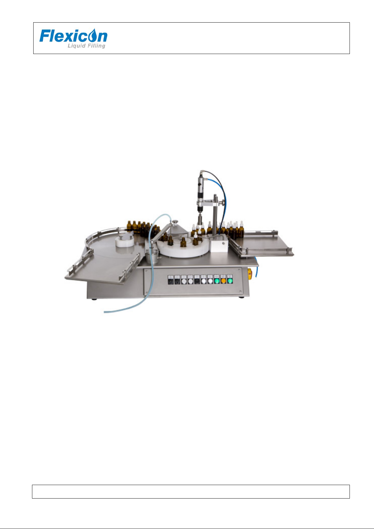
FF30 is a small-scale bottle handling, filling and capping machine.
A round table moves the bottles to the inlet, from which each bottle is moved further on by a star
wheel.
Filling is performed automatically, and capping is semi-automatic.
After capping the bottle is pushed to the outlet tray by a bottle ejector.
FF30 is delivered without the external filler; in order to perform the filling, a filler must be connected.
(See further informati on in section 2.4)
1.2 Abbreviations in this manual
1.3 Symbols on the machine
Warning against touching Warning against high voltage
FF30 IH EN 74-216-201 v1.20.doc Page 4 of 26
Page 5

INSTRUCTION HANDBOOK
FF30 V2
WM-Flexicon machines may not be disposed using normal refuse
*
1.4 Caution and employee safety
This manual should be read before using the FF30.
It is strongly advised that
- Any kind of maintenance or cleaning of the machine not is carried out while power is
connected
- Unauthorised / non-trained personnel should not open the cover of the electrical parts
- The machine is placed in such a way that it is not exposed to high humidity, high temperatures
or other abnormal operating environment.
- The machine is not to be used in explosion hazardous environments.
1.5 Essential training before daily use
Read the section with Daily Use, thoroughly before using the machine.
Protective equipment and protective devices are installed:
If the star wheel is jammed it will stop immediately
The capping machine will stop if it is unable to reach lower position during capping; e.g. this
way fingers or instruments will not be squeezed if they are placed between the cap and the
capping head during production.
Always respect the symbols on the machine.
Cleaning must be performed as described in this IH.
1.6 References
N/A
1.7 Dismantling and disposal
Prior to dismantling, it must be observed that all services are disconnected, and fixing to other
equipment is removed.
collection. The machines must be collected and disposed separately as
they contain electrical components such as batteries, electrolyte
capacitors, liquid crystal displays and printed circuit boards.
Further information is available on www.wmflexicon.dk.
* (WEEE) DS/EN 50419
FF30 IH EN 74-216-201 v1.20.doc Page 5 of 26
Page 6
INSTRUCTION HANDBOOK
FF30 V2
2 General information
2.1 Unpacking and inspection
Please check that all ordered items have been received and that no items are damaged during
transport. In case of any defects or omis s io ns , please contact WMF or your supplier immediately.
2.2 Receiving and storing the FF30
Before unpacking or storing of the FF30 it should be checked if the crate is damaged.
In case of long -term storage of the FF30 before installation, the machine must be stored in the crate,
and placed in a dry room. The crate is not water resistant.
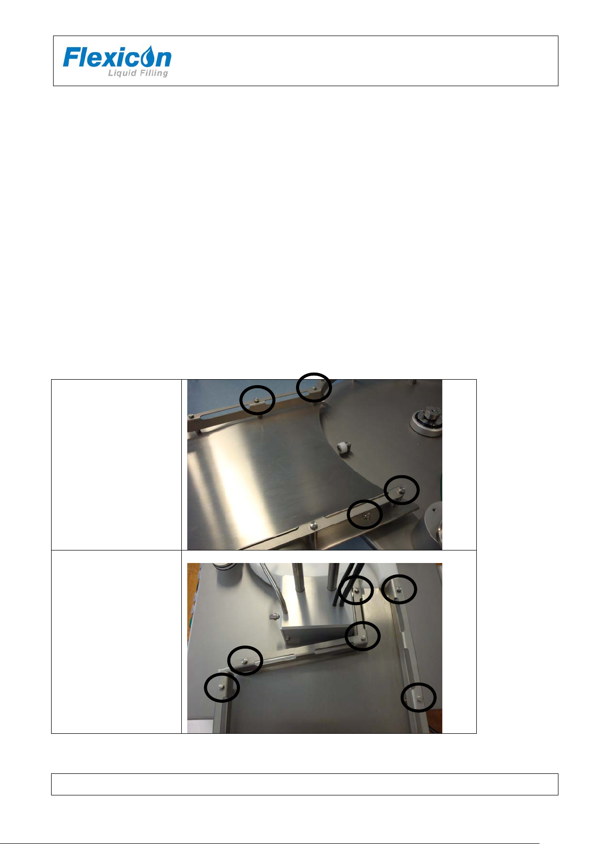
2.3 Mounting of support for inlet and outlet tray
If the inlet tray or outlet tray have been removed during shipping they must be mounted as shown
below. Use the supplied bolts and fasten them as shown below.
Inlet tray
Outlet tray
FF30 IH EN 74-216-201 v1.20.doc Page 6 of 26
Page 7
FF30 V2
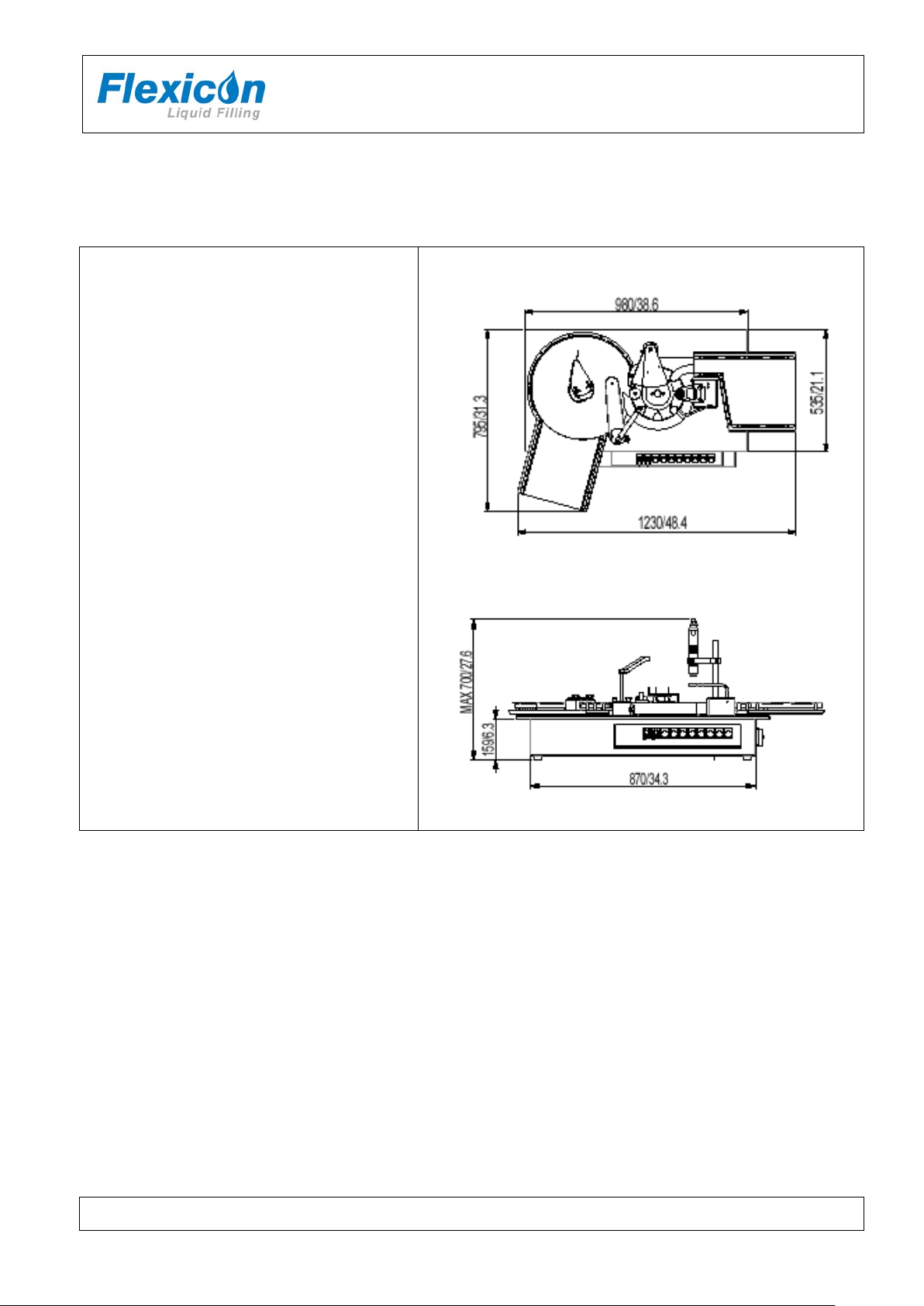
Dimensions: mm / inches
2.4 Technical specifications
2.4.1 Dimensions
Length: 1230 mm
Width: 795 mm
Height: max. 700 mm (incl. Feet)
INSTRUCTION HANDBOOK
FF30 IH EN 74-216-201 v1.20.doc Page 7 of 26
Page 8
FF30 V2
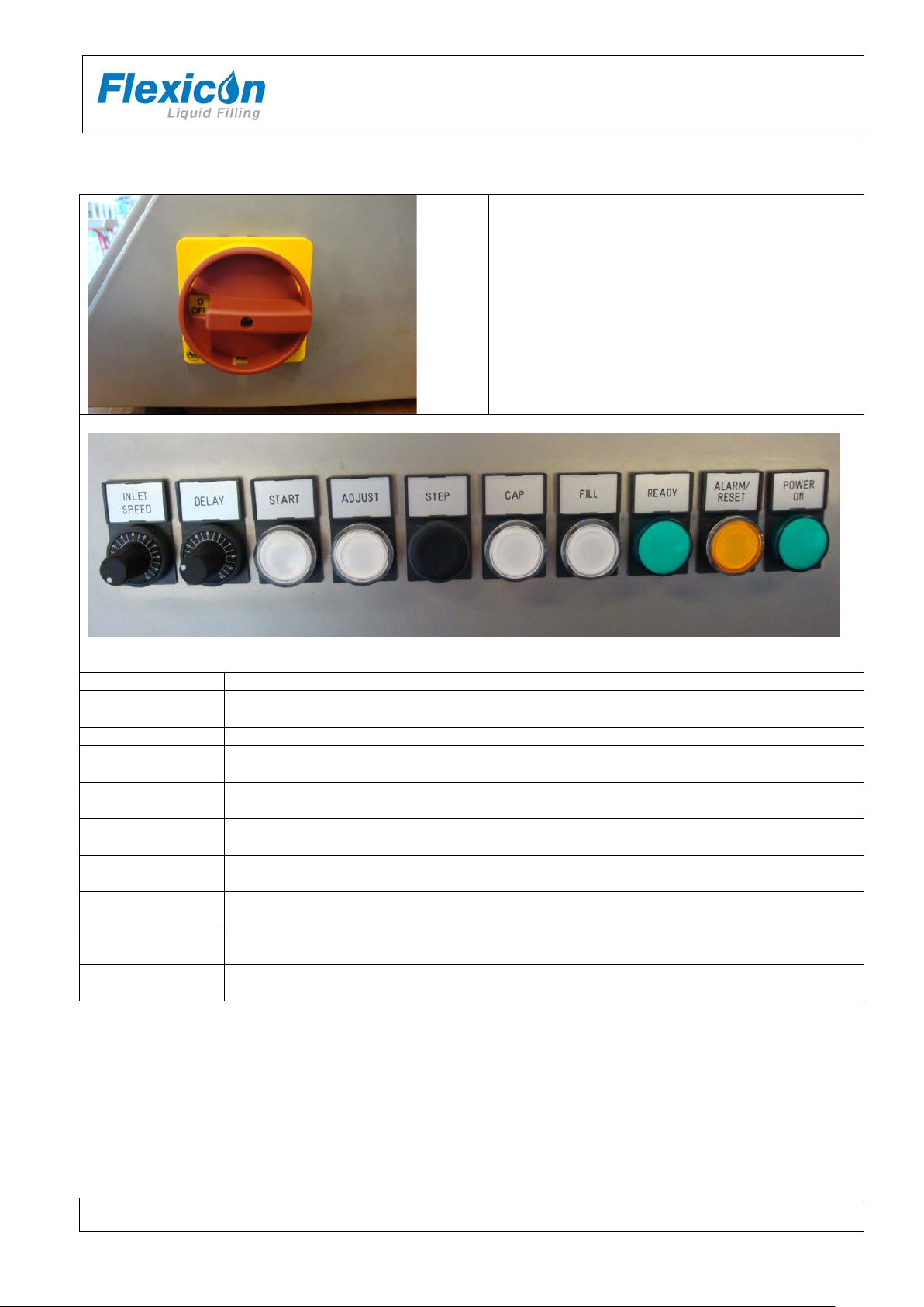
POWER ON
Green indicator whic h light s when po wer is on.
ALARM / RESET
Push button for cancelling errors.
The button flashes if an error occurs
READY
Green indicator which lights when FF30 is ready
FILL
Enables filling; signal to an external pump.
White indicator lights when the FILLING function is active.
CAP
Enables capping.
White indicator lights when the CAPPING function is active.
STEP
Push button.
One push activates one step with the star wheel.
ADJUST
Push button for adjustment mode.
White indicator lights when ADJUST is active.
START
Push button for starting and stopping production.
White indicator lights when START is active
DELAY
Potentiometer for adjusting the delay between each indexation.
0,5 = minimum time (~ fast process of bottles), 10 = maximum time (~ slow process)
INLET SPEED
Potentiometer for setting the speed of the round table.
0,5 = slow 10 = fast
2.4.2 Buttons / Control panel
INSTRUCTION HANDBOOK
ON/OFF – EMERGENCY SWITCH
Combined button: Main switch and Emergency
switch for the entire FF30
FF30 IH EN 74-216-201 v1.20.doc Page 8 of 26
Page 9

FF30 V2
switch
2.4.3 Services
All electrical system s are placed in the base cabinet.
INSTRUCTION HANDBOOK
Power supply:
Consumption: 300 W
Compressed air: 6 bar, clean and dry air
Consumption:
110/230 VAC, 50/60Hz
Earthed by the main power
75 L/min at 20 BPM
Note:
Only authorised personnel can gain access to the installations.
The main power cable must be removed completely from power supply before the base cabinet is
opened.
2.4.4 Bottles, caps and trays
Bottle sizes
Diameter Max Ø50 mm.
Height Max 110 mm.
Cap sizes
Diameter Max Ø50 mm.
Height Max 40 mm.
Tray size inlet / outlet
Inlet Outlet
Length / width* 290 mm / 260 mm 280-320 mm / 285 mm
Height of rail 30 mm 30 mm
*note – the trays are not rectangular. See picture on the front page.
2.4.5 Ingress protection
Ingress protection IP52
2.4.6 Weight
Weight: app. 60 kg
FF30 IH EN 74-216-201 v1.20.doc Page 9 of 26
Page 10

FF30 V2
2.4.7 Materials of construction
AISI304 stainless steel
anodised aluminium
Polyacetal
2.4.8 Fillers
A peristaltic filler or gear filler must be connected to FF30.
Optional fillers when filling are:
- PF6 Peristaltic filler
- 520 Di peristaltic filler
- DF32 Positive displacement filler
- GF30 gearfiller
INSTRUCTION HANDBOOK
FF30 IH EN 74-216-201 v1.20.doc Page 10 of 26
Page 11

FF30 V2
3 Installation
3.1 Connections
FF30 must be placed on a stable and horizontal bedplate.
INSTRUCTION HANDBOOK
The mains cable (1) is
connected to a single-phase
power supply with earth.
Compressed air is connected to
(2) by use of the supplied quick
release clutch.
All exhaust air is collected and
exhausted through the exhaust
filter (3)
The filler is connected to (4).
RS485 (5) is used for “remote
access” (e.g. during service, or
monitoring)
3
2
1
5
4
FF30 IH EN 74-216-201 v1.20.doc Page 11 of 26
Page 12

INSTRUCTION HANDBOOK
FF30 V2
Remove the finger screw
and dismount the bottle ejector.
Move the plate with the inlet sensor to the right
Move the star wheel
Finally move the guides one by one…
When the last guide has been removed another
the opposite way of the dismounting procedure.
3.2 Mounting of format parts
3.2.1 Bottle format parts
A set of bottle format parts consists of 1 star wheel and 3 guides. All 4 are marked with one number
which together composes the customised parts for one specific bottle size. The number does not
have any reference to the bottle size; it is merely a number which is engraved on the parts to ensure
that the matching parts can be recognized.
Change of bottle format parts
FF30 IH EN 74-216-201 v1.20.doc Page 12 of 26
size of format parts can be mounted. This is done
Page 13

INSTRUCTION HANDBOOK
FF30 V2
Mount the capping unit on the two steel columns
Mount the two hoses for
compressed air.
Hold the head with one hand
And with the other hand press
the quick coupling down
Pull the head down until it is
released from the coupling
3.2.2 Screw cap format parts
Screw cap format parts consist of 1 single capping head. If several sizes of capping heads have been
ordered, each size is marked with one number which together with the bottle format parts composes
the customised parts for one specific bottle size. The number does not have any reference to the
bottle size; it is merely a number which is engraved in the parts to ensure that the matching parts can
be recognized. E.g. bottle format parts marked with the number 1 – match the capping head marked
with the number 1.
Mounting of capping unit
Change of capping head
When mounting another size of capping head, it is not necessary to touch the quick coupling. Just
press the head into the coupling until it clicks.
FF30 IH EN 74-216-201 v1.20.doc Page 13 of 26
Page 14
INSTRUCTION HANDBOOK
FF30 V2
Correct adjustment
Wrong adjustment
4 Daily Use
4.1 Starting-up and running
Installation section must be carried out before this chapter can be performed.
When the main switch is turned, an initial procedure starts and secure that the machine is ready for
production. The POWER ON will light if no errors are detected.
In case of error detection during initial procedure the ALARM button will flash.
See section 5 regarding alarms.
4.1.1 Adjusting the round table i nner bottle r ail
Adjust the inner bottle rail by loosening the
bolts (finger screws) and move the rail in or
out; depending on bottle size. The bottles
should be stopped by the rail in such a way
that only one bottle at a time can pass the
space between the inner and outer rail.
4.1.2 Adjusting the inlet guide
Adjust the inlet guide by loosening the bolts (finger screws) and move it to the right or left; depending
on bottle size. The bottles should be let to the first position of the star wheel; never to the outside of
the star wheel.
FF30 IH EN 74-216-201 v1.20.doc Page 14 of 26
Page 15

FF30 V2
Loosen the finger screw at the bottom of the filling stand.
The nozzle tip should only be a few millimetres away from the bottle top to avoid squirt of product.
Place a bottle with a cap in front of the sensor.
Loosen the finger screw of the sensor and adjust until the light is just below the top of the cap.
4.1.3 Adjustment of the filling stand
INSTRUCTION HANDBOOK
Adjust the filling stand and the filling nozzle over the centre of the bottle – over the second bottle in the
star wheel.
4.2 Adjusting the capping sensor
The cap must be placed detachable on the top of the bottle – not screwed.
FF30 IH EN 74-216-201 v1.20.doc Page 15 of 26
Page 16

INSTRUCTION HANDBOOK
FF30 V2
Place a bottle with a cap underneath the capping
Pull the black clutch casing
Turn the capping head until the
Insert a screwdriver and adjust
Decrease = counter clockwise
4.3 Adjusting the height of capping head
Adjusting the height of the capping head must be repeated until the cap is tightened satisfactorily.
A correct capping function is depending on the placement of the capping unit, and the type of cap and
bottle.
unit. The cap must be tightened into end position.
Press ADJUST, to lower the capping unit.
Loosen the finger screw on the capping unit and
lower it until the capping head is resting on th e
top of the screw cap. Fasten the finger screw.
Now press ADJUST again, and the capping head
will return to top position.
Loosen the finger screw once more, and lower
the capping unit app. 5-10 mm before tightening
the finger screw again.
4.4 Adjusting the capping torque
sleeve down.
adjustment lock plate is visible
through the slot.
torque by turning.
Increase = clockwise
FF30 IH EN 74-216-201 v1.20.doc Page 16 of 26
Page 17

INSTRUCTION HANDBOOK
FF30 V2
4.5 Adjustments
4.5.1 Index speed adjustment
Speed is set via the DELAY function. The lower value, the faster the bottles will move from inlet to
filling and capping.
Press ADJUST (the capping machine will enter lower position)
Set speed on DELAY potentiometer, 0,5 = mini mum time (~ fast process), 10 = maximum time
(~ slow process)
Press START to save the value (note the value)
Turn DELAY back to 0
Press ADJUST again to return to normal mode
The value is saved when the machine is turned off.
4.5.2 Bottle ejector speed adjustment
Speed is set via the DELAY function. The lower value, the faster the bottles will be pushed onto the
outlet tray.
Press ADJUST (the capping machine will enter lower position)
Set speed on DELAY potentiometer, 0,5 = minimum time (~ fast process), 10 = maximum time
(~ slow process)
Press STEP to save the value (note the value)
Turn DELAY back to 0
Press ADJUST again to return to normal mode
The value is saved when the machine is turned off.
4.5.3 Capping time adjustment
Capping time adjustment is set via the DELAY function. The lower value the adjustment is set at, the
shorter time the capping head will use on screwing the cap into place. Note: If the time is too short
the cap might not be fastened enough.
Press ADJUST (the capping machine will enter lower position)
Set speed on DELAY potentiometer, 0,5 = minimum time (~ fast), 10 = maximum time (~ slo w)
Press CAP to save the value (note the value)
Turn DELAY back to 0
Press ADJUST again to return to normal mode
The value is saved when the machine is turned off.
4.5.4 Round table speed adjustment
See section 2.4.2
FF30 IH EN 74-216-201 v1.20.doc Page 17 of 26
Page 18

INSTRUCTION HANDBOOK
FF30 V2
4.6 Production START and STOP
FF30 is ready for production when:
bottles are placed on the inlet tray
the inner bottle rail is adjusted
the inlet guide is adjusted
filling stand is adjusted
the external filler is connected and ready
capping sensor is adjusted
height of capping head is set
the Index speed is set, if necessary
READY indicator is ON
Production can begin by pressing START. FILL and CAP must be activated before pressing START.
When a bottle is detected at the inlet the star wheel will begin the indexing, and the activated
functions start.
The time/pause between 2 indexing cycles can be adjusted via the DELAY function. If a function has
a longer cycle time than the setting of the DELAY, the indexing will be halted until all functions have
finished the cycle.
4.6.1 Manual placing of caps
Caps are to be applied on the bottles after filling has been performed.
The cap is placed with a small twist to prevent the cap from falling off during the following indexing.
The cap sensor is only active when the CAP button has been activated.
If a bottle enters in front of the sensor without a cap the FF30 will stop. Place the cap manually and
press CAP to continue production; or press STEP to end automatic production – the star wheel will
now move one position forward.
4.6.2 Removing bottles from collection tray
When the collection tray is full the operator must stop the machine and empty the tray.
When the outlet tray is full the operator can choose to stop the machine and empty the tray or to
empty the tray when production is ongoing and the tray is not packed.
4.7 Stepping bottles through the FF30
Pressing the STEP button will perform one indexing; the star wheel will move all bottles one function
forward. From inlet to filling > from filling to capping > from capping to outlet.
When pressing STEP, the star wheel and the bottle ejector will move whether a bottle is present or
not.
If filling is desired this must be activated manually from the filler.
If the CAP function is ON a cap must be applied to the bottle manually after the filling is performed.
By using the STEP function the star wheel can be emptied at the end of a batch.
If the STEP button is held down constantly the functions continue as long as there are bottles in the
star wheel.
FF30 IH EN 74-216-201 v1.20.doc Page 18 of 26
Page 19

INSTRUCTION HANDBOOK
FF30 V2
Alarm
No
Internal RS485 communication failure
with Round Table (RT) Controller
Only used with diving nozzle, for the RT
controller to be backwards compatible.
First check compressed air and air connection.
mechanical parts
First check for things obstructing the star wheel
sensors for motor-controller.
Alarm
No
Check if something (bottle or cap) is obstructing
the star wheel movement, remove the obstacle and
button to continue production.
5 Malfunctioning
The FF30 is equipped with control functions, which will stop the machine in the event of
malfunctioning. If a function error is detected, the yellow ALARM/RESET (A/R) button will begin to
flash and the FF30 will stop.
5.1 Start-up alarms
The alarm number is identified by observing both the A/R button together with the READY indicator.
By counting the number of flashes of the A/R button in between each flash of the READY indicator the
alarm number can be identified.
Description Actions
1
2 RT Controller not READY
3 Capping station not in top position
Indexing start-wheel is not in HOME
4
position
5.2 Runtime alarms
Description Indication Actions
Exchange cycle is
5
not completed.
A/R and
START buttons
are flashing
Open machine and check fuses, cables etc.
Next open machine and check sensor and
movement.
Next open machine and check fuses, motor and
press RESET button – depending on the position
of the star wheel, the actions are different:
- Something is stopping the star wheel at the
entrance: The star wheel reverses to start
position, where the obstacle can be
removed. Press the START button to
resume production
- Something is stopping the ejector arm from
pushing out: The ejector arm is returned to
the home position. The A/R is still flashing
and when pressing the RESET button twice
the ejector arm is moved out again to finish
the exchange cycle. Press the START
FF30 IH EN 74-216-201 v1.20.doc Page 19 of 26
Page 20

INSTRUCTION HANDBOOK
FF30 V2
Alarm
No
There are a couple of situations, where this
START button to continue production.
Cap station (top-
movement.
A/R and
are flashing
See the alarm description on alarm number 6 as
Press RESET button the reset the alarm.
9
N/A
N/A
N/A
A/R,
flashing
Fault inside machine the round table toothed
motor.
Description Indication Actions
alarm will be initiated:
- The capping head is obstructed during
the downwards movement: The capping
head is returned to top position. If the
bottle is in the correct position and
nothing seems to obstruct the downwards
movement, the machine has to be
opened to investigate sensors and/or
mechanical faults.
- The alarm is initiated after the capping is
finished: This could indicate to low airpressure. If this not the case then the
machine has to be opened to investigate
sensors and/or mechanical faults.
- Lack of air pressure
Capping cycle is
6
not completed
A/R and
CAP buttons are
flashing
Press the RESET button to reset the alarm and
7
8
10 Round table fault
sensor) not in top
during star wheel
Adjust cycle is not
completed
A/R, START and
CAP buttons are
flashing
ADJUST buttons
START and
FILL buttons are
Check air pressure, open machine to check
Press RESET button the reset the alarm.
the courses of the alarm are the same.
wheel is not turning; fault must be investigated
inside machine: Check toothed belt, fuses and
FF30 IH EN 74-216-201 v1.20.doc Page 20 of 26
Page 21

INSTRUCTION HANDBOOK
FF30 V2
Alarm
No
There are two distinctly different ways of
star wheel will move one position forward.
Depending on conditions for the alarm/warning
will leave fill mode and automatic mode.
Description of fault
Possible cause
The READY indicator does not go ON
- Compressed air is not connected
- The ejector arm is not in “home” position
The star wheel does not index
- The bottle inlet sensor does not see the bottle
- Check fuses
External filler does not start when a bottle is
present under nozzle
- Missing or loose cable from FF30 to filler
- The filler is not in “dispense mode”
Capping station runs even if cap is missing
- The cap sensor has been placed too low
Capping is not complete or torque is inconsistent
- Capping head is placed too high
capping
The bottle ejector does not move the bottle to the
- The ejector is not mounted correctly.
- Check fuses
5.3 Runtime warnings
A warning is used to turn the operator’s attention to halt situations, which must be solved in order to
continue production / running.
Description Indication Actions
responding to this alarm/warning.
Cap is not on
1
2
bottle at Capdetect position.
Filler is not
starting on start
signal
CAP button is
flashing
FILL button is
flashing
- Put a CAP on the bottle and press CAP
button to continue production.
- Press the STEP button. This will end the
automatic production (and capping) – the
there are the following possible actions:
- Start the filler manually.
e.g. on a PF6 Press DISP+GO
The FF30 will then continue and clear the
warning.
- Stop the automatic mode by pressing
either START or FILL buttons. The FF30
5.4 Trouble shooting
outlet tray
- The star wheel is not in “home” position
at the inlet
- A workstation has not finished the cycle
- The toothed belt needs tension
- The bottle slips in the star wheel during
- The toothed belt needs tension
FF30 IH EN 74-216-201 v1.20.doc Page 21 of 26
Page 22

INSTRUCTION HANDBOOK
FF30 V2
Cleaning of parts
May
autoclaved
Can be cleaned
alcohol 70%
Can be cleaned with
wiped off with dry a cloth
Stainless steel
AISI304
Anodized aluminium
Polyacetal
(POM)
Nylon
(Compressed Air tubes)
Optical sensors*
6 Cleaning
6.1 Cleaning Frequency
As FF30 is not in direct contact with the dispensed product, daily cleaning might not be necessary.
Cleaning might be determined by local sop’s and cleaning validations; but must never be with
detergents more potent than the ones below.
6.2 Preparations for cleaning
Before cleaning the machine:
Turn off the power
Remove the filling nozzle and the filling tubes
6.3 Cleaning Guidance
Correct cleaning of the FF30 is carried out by washing it off with water or deterge nts, usi ng a lint-free
firmly wrung cloth or lint-free paper towel; subsequently the machine is wiped off with a dry cloth.
6.4 Detergents or cleaning agents
Normal cleaning agents such as tepid/medium hot water, ethyl alcohol (ethanol) 70% and may be
used all over the machine.
The FF30 consists of stainle ss steel and anodized aluminium, and can be cleaned in several ways:
made of:
*Optical Sensors can be cleaned with alcohol, but over time this can cause a milky surface. Either avoid
cleaning the sensor optics with solvents or be sure to wipe them immediately afterwards with a soft dry cloth.
Recommendation:
Keep a log on the cleaning in order to keep a sense of perspective.
be
X X X
X X X
X X
X
X X*
with ethyl
water and afterwards
FF30 IH EN 74-216-201 v1.20.doc Page 22 of 26
Page 23

INSTRUCTION HANDBOOK
FF30 V2
7 Maintenance & service
7.1 Maintenance
Note: Maintenance of drive systems includes accessing the base cabinet and should be carried out
by technical staff, only.
7.1.1 Tension of toothed belt
Both the round table
and the star wheel
are driven by a toothed belt.
Normally these will not need tension,
but should be checked yearly.
7.1.2 Capping unit
The capping air motor requires lubrication in order to function optimal.
It is recommended to supply the air inlet with one drop of turbine oil before and after operation.
Recommended oil: Rocol Foodlube Multi-Lube with PTFE.
Remove the air hose and supply the air inlet with one
drop of oil.
FF30 IH EN 74-216-201 v1.20.doc Page 23 of 26
Page 24

INSTRUCTION HANDBOOK
FF30 V2
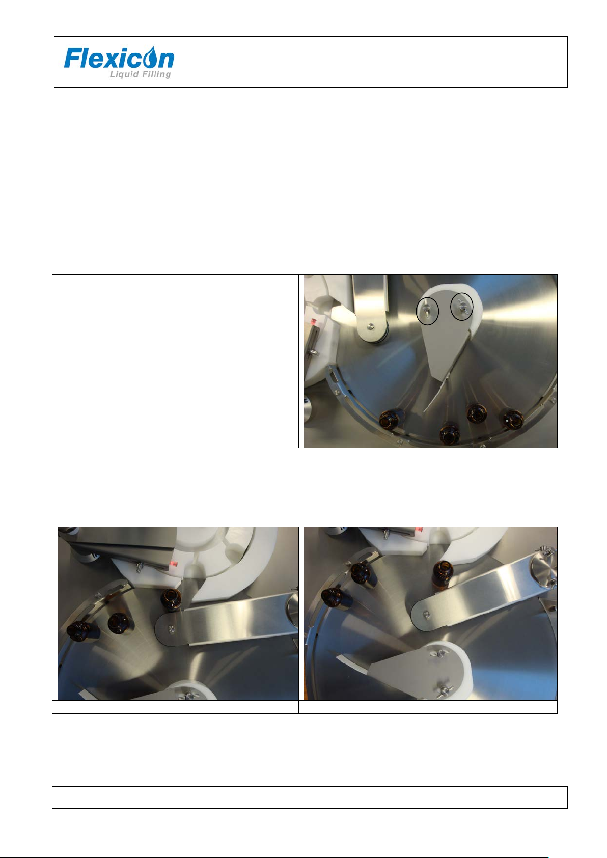
The contact faces between the carrier (red circle) and the Geneva wheel (black circle) should be
Note: it is the thin curved side of the wheel which is lubricated not the front or back.
The contact faces between the cam of the toothed pulley and the ejector arm should be lightly
lubricated with a suitable grease; e.g. Dow Corning MOLYKOTE grease BR2 plus.
7.1.3 Star wheel and bottle ejector
The drive systems of the star wheel and the ejector arm needs regular lubrication.
lightly lubricated with a suitable grease; e.g. Dow Corning MOLYKOTE grease BR2 plus.
FF30 IH EN 74-216-201 v1.20.doc Page 24 of 26
Page 25

INSTRUCTION HANDBOOK
FF30 V2
7.2 Service
Should service be needed, please contact W-M Flexicon or your local supplier.
7.3 Methods and frequency of inspections for safety functions
Safety functions should be tested once a year:
Emergency switch
When turned the entire FF30 is shut down
Keep a log and read the previous log recordings to present an overview of the machines state.
After testing the safety functions the results must be recorded in the log.
FF30 IH EN 74-216-201 v1.20.doc Page 25 of 26
Page 26

INSTRUCTION HANDBOOK
FF30 V2
Bottle handling
type
Item no
Model
FF30
92-350-xxx
62-315-000
DS EN/ISO 12100
Safety of machinery - Basic concepts, general
principles of design
DS/EN 60204
Safety of machinery – Electrical equipment of
machines
2006/42/EC
On the approximation of the laws of the Member
States relating to machinery
2006/95/EC
On the harmonization of the laws of Member States
within certain voltage limits
2004/108/EC
On the approximation of the laws of the Member
Jørn Jeppesen, Development Manager
8 Declaration of conform ity
We WM-Flexicon A/S
Frejasvej 2-6
DK-4100 Ringsted
Declare on our sole responsibility that the bottle handling units:
and capping unit
To which this declaration relates is in conformity with the following standard(s):
According to the provisions in the Directives:
relating to electrical equipment designed for use
States relating to electromagnetic compatibility
January 2011
Signature:
Ringsted, Denmark
FF30 IH EN 74-216-201 v1.20.doc Page 26 of 26
 Loading...