

Page 1

504U/RL
504u-gb-04.pdf
Page 2

DecDec
larlar
aa
lar
larlar
ee yee y
ee y
ee yee y
tionstions
a
tions
aa
tionstions
ear wear w
ear w
ear wear w
1, EMC Directive 89/336/EEC EN50081-1/EN50082-1.
machinery has been declared in conformity with the Machinery Directive 98/37/EC
EN60204-1.
arar
rr
antyanty
ar
r
anty
arar
rr
antyanty
Dec
DecDec
Declaration of When this pump unit is used as a stand alone pump it complies with:
Conformity Machinery Directive98/37/EC EN60204-1, Low Voltage Directive 73/23/EEC EN61010-
Declaration of When this pump unit is to be installed into a machine or is to be assembled with
Incorporation other machines for installations, it must not be put into service until the relevant
Responsible person: Christopher Gadsden, Managing Director, Watson-Marlow Limited, Falmouth, Cornwall TR11
4RU, England. Telephone 01326 370370, Fax 01326 376009.
TT
hrhr
T
hr
TT
hrhr
Watson-Marlow Limited warrants, subject to the conditions below, through either Watson-Marlow Limited, its
subsidiaries, or its authorised distributors, to repair or replace free of charge, including labour, any part of this
product which fails within three years of delivery of the product to the end user. Such failure must have occurred
because of defect in material or workmanship and not as a result of operation of the product other than in accordance
with the instructions given in this manual.
Conditions of and specific exceptions to the above warranty are:
• Consumable items such as tubing and rollers are excluded.
• Products must be returned by pre-arrangement carriage paid to Watson-Marlow Limited, its subsidiaries, or
its authorised distributor.
• All repairs or modifications must have been made by Watson-Marlow Limited, its subsidiaries, or its authorised
distributors or with the express permission of Watson-Marlow Limited, its subsidiaries, or its authorised
distributors.
• Products which have been abused, misused, or subjected to malicious or accidental damage or electrical
surge are excluded.
Warranties purporting to be on behalf of Watson-Marlow Limited made by any person, including representatives of
Watson-Marlow Limited, its subsidiaries, or its distributors, which do not accord with the terms of this warranty
shall not be binding upon Watson-Marlow Limited unless expressly approved in writing by a Director or Manager
of Watson-Marlow Limited.
InfInf
ormaorma
tion ftion f
or ror r
Inf
orma
ormaorma
tion f
tion ftion f
InfInf
Equipment which has been contaminated with, or exposed to, body fluids, toxic chemicals or any other substance
hazardous to health must be decontaminated before it is returned to Watson-Marlow Limited or its distributor.
A certificate included at the rear of these operating instructions, or signed statement, must be attached to the
outside of the shipping carton.
This certificate is required even if the pump is unused. If the pump has been used, the fluids that have been in
contact with the pump and the cleaning procedure must be specified along with a statement that the equipment
has been decontaminated.
eturning pumpseturning pumps
or r
eturning pumps
or ror r
eturning pumpseturning pumps
SafSaf
etyety
Saf
ety
SafSaf
etyety
In the interests of safety, this pump and the tubing selected should only be used by competent, suitably trained
personnel after they have read and understood this manual, and considered any hazard involved.
Any person who is involved in the installation or maintenance of this equipment should be fully competent to carry
out the work. In the UK this person should also be familiar with the Health and Safety at Work Act 1974.
2
Page 3

There are dangerous voltages (at mains potential) inside the pump. If access is required, isolate
the pump from the mains before removing the cover.
RR
ecommended operecommended oper
R
ecommended oper
RR
ecommended operecommended oper
DO keep delivery and suction lines as short as possible using a minimum number of swept bends.
DO use suction and delivery pipelines with a bore equal to or larger than the bore of the tube fitted in the
pumphead. When pumping viscous fluids, the losses caused by increased friction can be overcome by using
pipe runs with a cross sectional area several times greater than the pumping element.
DO run at a slow speed when pumping viscous fluids. When using the 501RL pumphead, a 4.8 or 6.4mm bore
tube with a 1.6mm wall will give best results. Tube smaller than this will generate a high friction pressure loss, so
reducing the flow. Tube with a larger bore will not have sufficient strength to restitute. Flooded suction will enhance
pumping performance in all cases, particularly for materials of a viscous nature. For improved performance with
viscous materials or for lighter suction lift and discharge pressure use 2.4mm wall tubing in the 501RL2 pumphead,
for speeds up to 200rpm.
DO keep the track and rollers clean.
DO fit an extra length of pump tube in the system to enable tube transfer. This will extend tube life and minimise
the down time of the pumping circuit.
The self-priming nature of peristaltic pumps means valves are not required. Any valves fitted must cause no
restriction to flow in the pumping circuit.
aa
ting prting pr
a
ting pr
aa
ting prting pr
ocedurocedur
ocedur
ocedurocedur
eses
es
eses
When using Marprene or Bioprene tubing, after the first 30 minutes of running, re-tension the tube in the
pumphead by releasing the tube clamp on the delivery side a little and pulling the tube tight. This is to counteract
the normal stretching that occurs with Marprene and Bioprene, which can go unnoticed and result in reduced tube
life.
Tube selection The chemical compatibility list published in the Watson-Marlow catalogue is only a guide. If in
doubt about the compatibility of a tube material and the duty fluid, request a tube sample card for immersion trials.
InstallaInstalla
Installa
InstallaInstalla
The 504U/RL is suitable for single phase mains electricity supplies only.
To ensure correct lubrication of the gearbox the pump should be run only while its feet are standing on a horizontal
surface. The pump should be positioned to allow a free flow of air around it.
• Remove the small transparent plate on the rear panel to gain access to the voltage selector and terminal
• Set the voltage selector switch to either 120V for 100-120V 50/60Hz single phase AC supplies or 240V for
• Route the mains supply cable through the entry point to the right of the recess and couple the cable to the
• The cable entry accepts three core 0.75 square millimetre PVC sheathed mains cable (via the screw adaptor
• Ensure that the mains lead is securely retained in the strain relief gland so that IP55 ingress protection is
• Securely replace the transparent plate and the gasket over the recess.
tiontion
tion
tiontion
block.
220-240V 50/60Hz single phase AC supplies.
terminal block as shown on the rear panel.
supplied) so that a mains lead can be used.
maintained.
1 Power cable 5-8mm O.D. (outside diameter)
2 Strain relief gland SL 0020
3 Adaptor MR0678T
4 M20 Conduit thread for direct conduit connection, through
back panel
3
Page 4

Ingress protection standard will be compromised if fittings are not correctly replaced.
RR
ear panel rear panel r
R
ear panel r
RR
ear panel rear panel r
The pump rear panel recess houses the following:
1 Signal offset potentiometer 2 Tachometer switch 3 Voltage selection switch 4 Terminal block
5 Fuse holder 6 Signal overload LED 7 Signal range potentiometer.
TT
rr
ouboub
leshootingleshooting
T
r
oub
leshooting
TT
rr
ouboub
leshootingleshooting
Should the unit fail to operate, make the following checks to determine whether or not servicing is required.
• Check that the power switch is on.
• Check the mains supply is available at the pump unit.
• Check the voltage selector switch is in the correct position.
• Check the fuse in the mains socket.
• Check that the pump is not stalled by incorrect fitting of tubing.
ecessecess
ecess
ecessecess
ManMan
ual operual oper
Man
ual oper
ManMan
ual operual oper
Start up direction Start the pump by turning the Forward/Off/Reverse switch to the required direction of rotation.
The preferred direction of rotation is clockwise (with fluid entering at the bottom of the right of the pumphead),
which will ensure the longest possible tube life. To operate against higher pressures, use counterclockwise rotation.
Prime To prime the pump at maximum speed turn the Auto/Manual/Max switch on the front panel to its Max
position. When released the switch will return to its Manual position.
Speed control The speed setting dial is calibrated in percentage of maximum speed and has a locking knob to
prevent accidental speed changes.
Stop Stop the pump by turning the Forward/Off/Reverse switch to its central Off position. To change the
direction of flow, turn the Forward/Off/Reverse switch to its central Off position until the pumphead rotor stops,
and turn it to the required direction of rotation.
If returning from auto control to manual control, it is not necesssary to disconnect the process signal from the
pump or adjust the calibration potentiometers.
aa
a
aa
tiontion
tion
tiontion
4
Page 5

AutomaAutoma
Automa
AutomaAutoma
Set the Auto/Man/Max switch to Auto.
For all auto and remote control operations, the drive is supplied with a 6 pin waterproof connector (UP 0055).
The pump is controllable by an analogue process signal of up to 30V or 32mA. The pump will provide an increasing
flow rate for rising control signals (non-inverted response) or an increasing flow rate for falling control signal
(inverted response).
tic opertic oper
tic oper
tic opertic oper
aa
tiontion
a
tion
aa
tiontion
Correct assembly of the 6 pin plug is essential or the ingress protection standard will be
compromised. Never apply mains voltage across any pins on the 6 pin socket. Up to 30V
may be applied across pins 2 and 3, but not across other pins because permanent damage,
not covered by warranty may result.
• Signal offset is the process signal level which has to be reached in order for the pump rotor to start rotating.
• Signal range is the change in process signal level necessary to produce the required change in pump rotor
speed.
For example, when using a 4mA to 20mA process signal:
Pump Response Signal Offset Signal range
Non-Inverted 4mA 16mA
Inverted 20mA 16mA
For voltage modes a stable variable DC voltage source can be used in conjunction with a DC voltmeter, (maximum
30V DC) or a remote potentiometer. Polarity set for non-inverted response. Reverse polarity for inverted response.
Voltage signal
Input impedance 220 kohm
Response Range V Offset V Pin 2 Pin 3
Non-inverted 5 to 30 0 to 30 – +
inverted 5 to 30 0 to 30 + –
For current modes the same DC source can be used in conjunction with a DC milliampere meter. Polarity set for
non-inverted response. Reverse polarity for inverted response.
Current signal
Input impedance 250 ohm
5
Page 6

Response Range mA Offset mA Pin 2 Pin 3
Non-inverted 12 to 30 0 to 30 – +
inverted 12 to 30 0 to30 + –
CalibrCalibr
Calibr
CalibrCalibr
Ensure the correct wiring of the 6 pin plug and insert the plug into the socket at the rear of the pump.
• Remove the rear panel recess window.Turn the signal offset potentiometer clockwise until the slider traverse
• Repeat for the signal range potentiometer. This ensures correct potentiometer set up for calibration.Set the
• Turn the signal offset potentiometer clockwise to set the drive shaft speed to the desired minimum.
• Set the process signal at its upper range limit (not exceeding 30V or 32mA).
• Turn the signal range potentiometer clockwise to set the drive shaft speed to the desired maximum.
• Repeat the procedure until pump response coincides exactly with the process signal.
If the signal rises above its designated maximum, the action of the signal conditioner will be to hold the motor to
maximum speed at the MAX setting indicated by the flashing of the LED indicator. If the signal rises above 30V,
permanent damage, not covered by warranty, may result.
RR
R
RR
aa
tion ftion f
a
aa
limit is reached and is signified by a clicking noise. Now turn the potentiometer ten turns anticlockwise.
process signal offset.
emote contremote contr
emote contr
emote contremote contr
or auto contror auto contr
tion f
or auto contr
tion ftion f
or auto contror auto contr
olol
ol
olol
Securely replace the rear panel recess on the back of the pump ensuring the gasket is in the
correct position. This will avoid the ingress protection standard of the pump unit being
compromised.
olol
ol
olol
Stop/Start
Connect remote switch between pins 1 and 5 of the 6 pin socket. Close contact to stop the pump, open to run.
A TTL compatible logic input (Low 0V, High 5V) may be applied to pin 5 (pin 2 common) with 5V High = stop, 0V
low = run).
6
Page 7

Speed
A remote potentiometer with a nominal value of between 4.7kohm and 5 kohm should be wired as shown, When
using a remote potentiometer do not connect a voltage/current control signal at the same time. The speed control
signal will require calibration relative to the minimum and maximum settings of the potentiometer. Use the offset
and range potentiometers as described under Calibration for auto control.
Tachometer output
This facility can be used to indicate motor speed or total the number of motor revolutions. Select either 1) 0-5V DC
or 2) 5V pulse train output using the tachometer output switch.
CarCar
e and maintenancee and maintenance
Car
e and maintenance
CarCar
e and maintenancee and maintenance
The only scheduled maintenance of the pump unit is to inspect the motor brushes and to replace them before their
length is less than 10mm. The life of the brushes depends on the duty of the pump but is expected to be at least
4,000 hours at maximum speed.
If the pump requires cleaning use a mild solution of detergent in water after removing the pumphead. Do not use
strong solvents.
For gearbox rebuilds, use 15ml of the recommended lubricant RD-105. This is a SAE 30 mineral oil loaded with
molybdenum disulphide to form a soft fluid grease.
SpecifSpecif
Specif
SpecifSpecif
icaica
tiontion
ica
tion
icaica
tiontion
Maximum rotor speed 55rpm, 220rpm, 300rpm
Shaft torque 2.2Nm
Control range 100:1
Voltage/frequency 100-120/220-240V 50/60Hz
Power consumption 100VA
Operating temperature range 5C to 40C
Storage temperature range -40C to 70C
Noise <70dB(A) at 1m
Weight 9.0kg
Standards EN60529 (IP55)
Machinery Directive 98/37/EC EN60204-1
Low Voltage Directive 73/23/EEC EN61010-1
EMC Directive 89/336/EEC EN50081-1/EN50082-1
7
Page 8

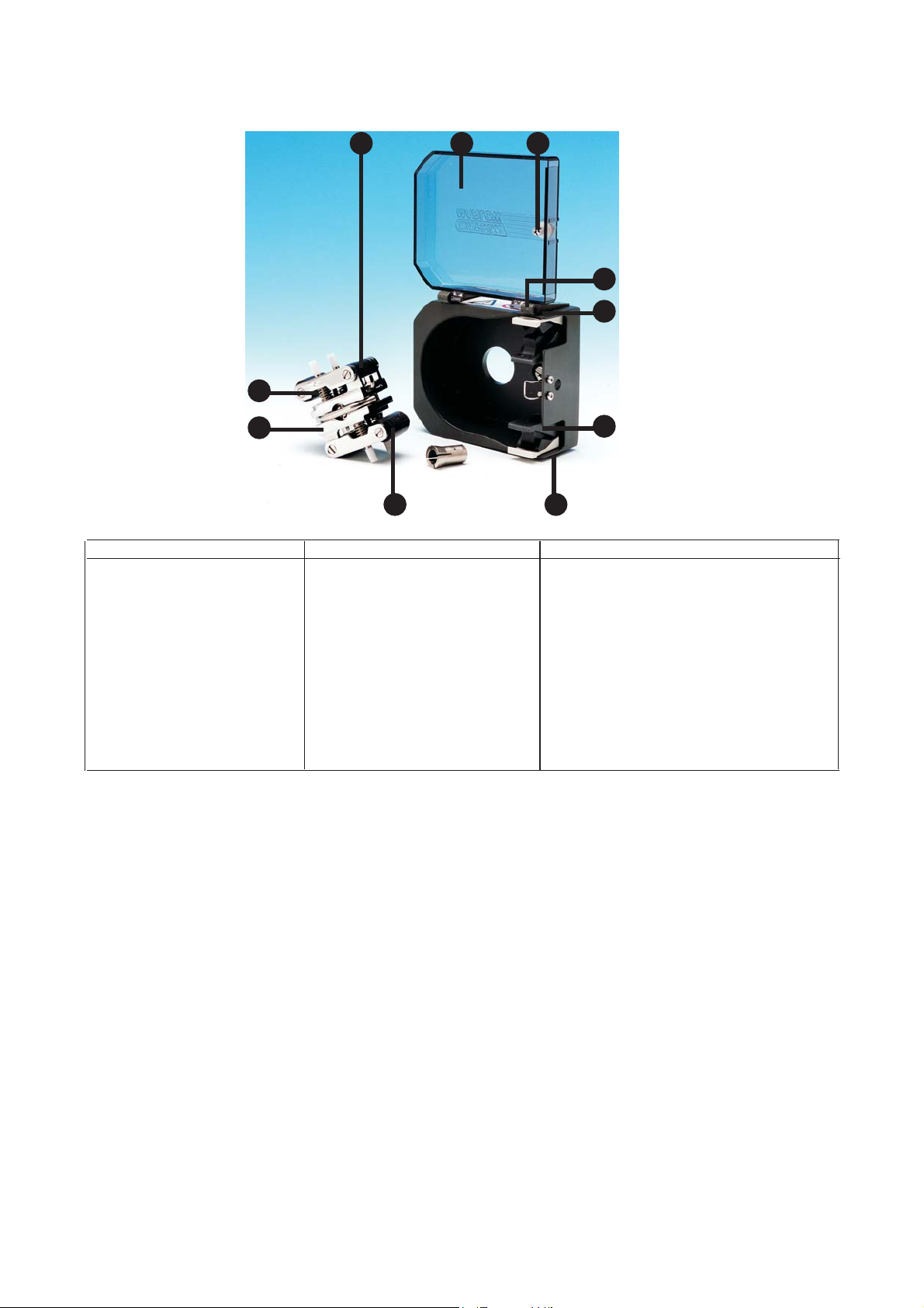
501RL Pumphead501RL Pumphead
501RL Pumphead
501RL Pumphead501RL Pumphead
The 501RL pumphead has two spring-loaded working rollers, which automatically compensate for minor variations
in tubing wall thickness, giving extended tube life. The 501RL is set during manufacture to accept tubing with wall
thicknesses of between 1.6mm and 2.0mm, and internal diameters of up to 8.0mm. It is equipped with a “tool
lockable” guard for increased safety. This should be locked shut whilst the pump is in use. The pumphead can be
run clockwise for extended tube life, or anti-clockwise to operate against higher pressures.
FF
low rlow r
aa
F
low r
FF
low rlow r
Flow rates for the 504U were obtained using silicone tubing with the pumphead rotating clockwise, pumping water
at 20C with zero suction and delivery pressures. For critical applications determine flow rates under operating
conditions.
a
aa
testes
tes
testes
InstallaInstalla
Installa
InstallaInstalla
Remove the grub screws on the drive front panel to enable the pumphead to be fitted.
Fit the track in any one of three orientations, over the drive shaft and locating boss. Secure the track with the
locating screw. Ensure the drive shaft is degreased before locating the rotor onto the shaft via the split collet.
Rotate the rotor until its guide rollers are aligned flush to the front edge of the track. Tighten the rotor screw to a
torque of 3Nm to prevent the collet slipping during operation.
To reposition the track, swing out the crank handle to expose the rotor retaining screw. Turn the screw anticlockwise
one turn to release the collet, and withdraw the rotor from the shaft. Loosen the track locating screw, and pull the
track clear. Rotate the track to its new position and tighten the track locating screw. Use this method of removal
and fitting if cleaning is required.
tiontion
tion
tiontion
TT
ube loadingube loading
T
ube loading
TT
ube loadingube loading
Isolate pump from mains supply. Unlock and open the hinged guard and swing out the rotor crank handle until it
locks into position. Select the length of tubing required, noting that approximately 240mm is required for the
501RL track.
Fit one end of the tubing into one of the spring loaded clamps, and then, whilst rotating the rotor with the crank
handle, feed the tubing between the rollers and the track, aligning it within the rotor tube guides. The tubing must
lie naturally against the track and must not be twisted or stretched.
8
Page 9

Fit the other end of the tubing into the second spring loaded clamp, ensuring that the tubing is not slack in the
pumphead, since this can reduce tube life.
Close the crank handle and shut and lock the guard.
After the pump has been started, open the downstream clamp for a short time, so that the tube can find its natural
length.
The 501RL pumphead is fitted with four-position tube clamps, to accommodate various tube diameters, which can
be adjusted by pushing in or pulling out the bars at the top of the upper clamp and the bottom of the lower clamp.
Set the clamps so that the minimum necessary pressure is applied to the tubing.
RR
oller adjustmentoller adjustment
R
oller adjustment
RR
oller adjustmentoller adjustment
The 501RL has a factory set gap of 2.6mm between the rollers and the track and is suitable for tubing having wall
thicknesses of between 1.6 and 2.0mm. Adjustment of the gap will be required if tubing having a wall thickness of
less than 1.6mm is required. There is an adjusting screw on each of the two roller arms, and each of these screws
will require adjustment. The correct gap is twice the wall thickness less twenty percent. Correct adjustment is
important: over occlusion will reduce tube life; under occlusion will reduce pumping efficiency.
To change the gap setting, turn each adjusting screw clockwise to increase the gap, or anticlockwise to decrease
the gap. A full turn changes the gap by 0.8mm.
To restore the original settings of 2.6mm, turn the adjusting screws until both rollers are just touching the track,
then tighten each screw by three and a quarter turns. The 501RL2 has a factory set gap of 3.8mm between the
wall and the track and is suitable for tubing having wall thickness of between 2.1 and 2.5mm.
Check moving parts of the rotor from time to time for freedom of movement. Lubricate pivot points and rollers
occasionally with a light machine oil with Teflon additives. For scheduled maintenance, remove the rotor from the
pumphead, clean thoroughly and apply light machine oil with Teflon additives to the roller spindles.
9
Page 10
Pumphead sparPumphead spar
Pumphead spar
Pumphead sparPumphead spar
eses
es
eses
1010
10
1010
99
9
99
88
8
88
77
7
77
Number Spare Description
1 MN 1200M Lockable guard
2 FN 4502 Lock
3 FN 2341 Hinge screw
4 MN 0266M Hinge grey
5 MNA0114A Tube clamp assembly
6 FN 2332 Screw
7 MN 0011T Main roller
8 MNA0143A 501RL Rotor Assembly
9 SG0001/SG0002 Springs standard (1.6mm) / hard (2.4mm)
10 MN 0012T Follower roller
XX 0095 Teflon lubricant
11
1
11
22
2
22
33
3
33
44
4
44
55
5
55
66
6
66
10
Page 11

DrivDriv
Driv
DrivDriv
e spare spar
e spar
e spare spar
eses
es
eses
1717
17
1717
16
1616
1414
14
1414
1313
13
1313
1818
18
1818
11
1
11
22
2
22
33
3
33
44
4
44
1515
15
1515
1616
55
5
55
66
6
66
Number Spare Description
1 MNA0388A Motor/gearbox 220rpm/ 300rpm
1 MNA0396A Motor/gearbox 55rpm
2 MRA0613A Transformer
3 MNA0543A Tachometer PCB
4 MN0787M Tachometer disc
5 MN0487S Top/bottom case gasket
6 MN0488S Front/rear panel gasket
7 UP0055 6 pin plug
US0055 6 pin socket
8 SW0086 Voltage selector switch
9 FS0024 Fuse T type 2 amp
10 MR0669S Window cover plate
11 SL0020 Cable gland
12 FA 0002 Filter
13 MNA0546A PCB assembly 55rpm, 220rpm
MNA0639A PCB assembly 300rpm
14 FS0028 Fuse T type 0.4 amp
15 MR0769B Potentiometer
16 SW0110 Direction switch
17 FN0477 Blanking screws
18 SW0109 Auto/manual/max switch
77
7
77
88
99
8
88
1010
9
10
99
1010
1111
11
1111
1212
12
1212
11
Page 12

Specific drive performance details such as loaded drive speed variation against mains supply voltage fluctuation
and drive stability from a cold start to normal operating temperature are available on request. For further information
please contact Watson-Marlow Technical Support Department.
12
Page 13

##
#
##
English Tube number Tube bore rpm Stop
English Pressure (+) Suction clockwise anti-clockwise
rpm rpm
501RL
Flow rates
# 112 13 14 16 25 17 18
mm 0.5 0.8 1.6 3.2 4.8 6.4 8.0
“ 1/50 1/32 1/16 1/8 3/16 1/4 5/16
55 2.3 6.7 24 100 220 350 550
220 9.2 27 94 410 890 1400 2200
501RL2
Flow rates
#141625 1718
mm 1.6 3.2 4.8 6.4 8.0
“ 1/16 1/8 3/16 1/4 5/16
55 40 125 230 385 495
220 155 500 925 1540 1980
313/314 (ml/min)
Flow rates
# 112131416 251718
mm 0.5 0.8 106 3.2 4.8 6.4 8.0
“ 1/50 1/32 1/16 1/8 3/16 1/4 5/16
313
55 1.5 3.9 15 55 121 198 275
220 6.6 15 60 220 484 792 1100
314
55 1.5 3.3 13 46 104 165 220
220 6.6 13 55 186 418 660 880
13
Page 14

Maximum number of pumpheads
313/314 Peroxide/ Platinum silicone
112 13 14 16 25 17 18 112 13 14 16 25 17 18
#
mm 0.5 0.8 1.6 3.2 4.8 6.4 8.0 0.5 0.8 1.6 3.2 4.8 6.4 8.0
“ 1/50 1/32 1/16 1/8 3/16 1/4 5/16 1/50 1/32 1/16 1/8 3/16 1/4 5/16
55 6666643 6666533
2206666643 6666533
313/314 Marprene, Tygon, Neoprene, Fluorel
# 112 13 14 16 25 17 18 112 13 14 16 25 17 18
mm 0.5 0.8 1.6 3.2 4.8 6.4 8.0 0.5 0.8 1.6 3.2 4.8 6.4 8.0
“ 1/50 1/32 1/16 1/8 3/16 1/4 5/16 1/50 1/32 1/16 1/8 3/16 1/4 5/16
55 6666533 6666433
2206666533 6666433
501RL, 501RLG, 313, 314
Product codes
mm “ # Marprene Bioprene Peroxide Silicone Platinum Silicone
0.5 1/50 112 902.0005.016 903.0005.016 910.0005.016 913.A005.016
0.8 1/32 13 902.0008.016 903.0008.016 910.0008.016 913.A008.016
1.6 1/16 14 902.0016.016 903.0016.016 910.0016.016 913.A016.016
3.2 1/8 16 902.0032.016 903.0032.016 910.0032.016 913.A032.016
4.8 3/16 25 902.0048.016 903.0048.016 910.0048.016 913.A048.016
6.4 1/4 17 902.0064.016 903.0064.016 910.0064.016 913.A064.016
8.0 5/16 18 902.0080.016 903.0080.016 910.0080.016 913.A080.016
mm “ # STA-PURE* Chem-Sure* Neoprene Tygon
0.8 1/32 13 920.0008.016
1.6 1/16 14 960.0016.016 965.0016.016 920.0016.016 950.0016.016
3.2 1/8 16 960.0032.016 965.0032.016 920.0032.016 950.0032.016
4.8 3/16 25 960.0048.016 965.0048.016 920.0048.016 950.0048.016
6.4 1/4 17 960.0064.016 965.0064.016 920.0064.016 950.0064.016
8.0 5/16 18 920.0080.016 965.0080.016 920.0080.016 950.0080.016
mm “ # Fluorel Butyl
1.6 1/16 14 970.0016.016 930.0016.016
3.2 1/8 16 970.0032.016 930.0032.016
4.8 3/16 25 970.0048.016 930.0048.016
6.4 1/4 17 970.0064.016 930.0064.016
8.0 5/16 18 970.0080.016 930.0080.016
14
Page 15
501RL2, 501RL2G
Product codes
mm “ Peroxide Silicone Platinum Silicone Marprene Bioprene
1.6 1/16 910.0016.024 913.A016.024 902.0016.024 903.0016.024
3.2 1/8 910.0032.024 913.A032.024 902.0032.024 903.0032.024
4.8 3/16 910.0048.024 913.A048.024 902.0048.024 903.0048.024
6.4 1/4 910.0064.024 913.A064.024 902.0064.024 903.0064.024
8.0 5/16 910.0080.024 913.A080.024 902.0080.024 903.0080.024
9.6 3/8 910.0096.024 913.A096.024 902.0096.024 903.0096.024
mm “ STA-PURE* Chem-Sure*
1.6 1/16 960.0016.024 965.0016.024
3.2 1/8 960.0032.024 965.0032.024
4.8 3/16 960.0048.024 965.0048.024
6.4 1/4 960.0064.024 965.0064.024
8.0 5/16 960.0080.024 965.0080.024
* 501RL2G
505L, 505LG
(2.4mm) Product codes
Peroxide Platinum Marprene STA-PURE Chem-Sure
mm “ # Silicone Silicone
1.6 1/16 119 910.E016.024 913.AE16.024 902.E016.024 960.E016.K24 965.E016.K24
3.2 1/8 120 910.E032.024 913.AE32.024 902.E032.024 960.E032.K24 965.E032.K24
4.8 3/16 15 910.E048.024 913.AE48.024 902.E048.024 960.E048.K24 965.E048.K24
6.4 1/4 24 910.E064.024 913.AE64.024 902.E064.024 960.E064.K24 965.E064.K24
8.0 5/16 121 910.E080.024 913.AE80.024 902.E080.024 960.E080.K24 965.E080.K24
9.6 3/8 122 910.E096.024 913.AE96.024 902.E096.024
9.6 3/8 122 910.H096.024 (high flow element)
15
Page 16

Outline dimensions
501RL
Flow rates
335
65
2500
2250
2000
1750
1500
1250
1000
750
500
250
ml/min
(-) mbar
320
0
16
(-) ft H20
(220)
(220)
240
12 8 4
160
80
8.0
4.8
3.2
6.4
(+) bar
(+) psig
45
3
0.6
0.4
0.2
USgpm
0
15
1
2
30
0
0
0
0
16
Page 17

Watson-Marlow, Bioprene and Marprene are trademarks of Watson-Marlow Limited.
Tygon is a trademark of the Saint Gobain Performance Plastics Company.
STA-PURE and Chem-sure are trademarks of W L Gore & Associates
Warning, These products are not designed for use in, and should not be used for patient connected applications.
The information contained in this document is believed to be correct but Watson-Marlow Limited accepts no liability for any errors it
contains, and reserves the right to alter specifications without notice.
17
Page 18

Product Use and Decontamination Certificate
In compliance with the UK Health & Safety at Work Act and the Control of Substances Hazardous to Health Regulations you,
the user are required to declare the substances which have been in contact with the product(s) you are returning to Watson-Marlow or
any of its subsidiaries or distributors. Failure to do so will cause delays in servicing the product. Therefore, please complete this form
to ensure that we have the information before receipt of the product(s) being returned. A FURTHER COPY MUST BE ATTACHED TO
THE OUTSIDE OF THE PACKAGING CONTAINING THE PRODUCT(S). You, the user, are responsible for cleaning and
decontaminating the product(s) before returning them.
Please complete a separate Decontamination Certificate for each pump returned.
RGA No: ...............................................................
1. Company ..............................................................................................................................................................................
Address ..............................................................................................................................................................................
....................................................................................... Postcode ........................................................
Telephone ....................................................................................... Fax number ........................................................
2. Product ..................................................
2.1 Serial number ..................................................
2.2 Has the product been used?
YES NO If yes, please complete all the following Sections. If no, please complete Section 5 only
3. Details of substances pumped
3.1 Chemical names
(a) ..................................................................................
(b) ..................................................................................
(c) ..................................................................................
(d) ..................................................................................
3.2 Precautions to be taken in handling these substances
(a) ..................................................................................
(b) ..................................................................................
(c) ..................................................................................
(d) ..................................................................................
Note: Please describe current faults ...............................................................................................................................................
............................................................................................................................................................................................................
............................................................................................................................................................................................................
............................................................................................................................................................................................................
3.3 Action to be taken in the event of human contact
(a) ..................................................................................
(b) ..................................................................................
(c) ..................................................................................
(d) ..................................................................................
3.4 Cleaning fluid to be used if residue of chemical is
found during servicing
(a) ..................................................................................
(b) ..................................................................................
(c) ..................................................................................
(d) ..................................................................................
4. I hereby confirm that the only substances(s) that the
equipment specified has pumped or come into contact
with are those named, that the information given is
correct, and the carrier has been informed if the
consignment is of a hazardous nature.
Watson-Marlow Bredel Pumps Falmouth Cornwall TR11 4RU England Tel:+44 (0) 1326 370370 Fax: +44 (0) 1326 376009
5. Signed ...................................................................
Name ...................................................................
Position ...................................................................
Date ...................................................................
18
 Loading...