

Page 1

504S
504s-gb-03.pdf
Page 2

Declarations
98/37/EC EN60204-1, Low Voltage Directive 73/23/EEC EN61010-1, EMC Directive 89/336/EEC
Declaration of
conformity
Declaration of
Incorporation
Responsible person: Dr R Woods, Managing Director, Watson-Marlow Limited, Falmouth, Cornwall TR11 4RU, England.
Telephone 01326 370370, Fax 01326 376009.
When this pump unit is used as a stand alone pump it complies with: Machinery Directive
EN50081-1/EN50082-1.
When this pump unit is to be installed into a machine or is to be assembled with other
machines for installations, it must not be put into service until the relevant machinery has been
declared in conformity with the Machinery Directive 98/37/EC EN60204-1.
Three year warranty
Watson-Marlow Limited warrants, subject to the conditions below, through either Watson-Marlow Limited, its subsidiaries, or its
authorised distributors, to repair or replace free of charge, including labour, any part of this product which fails within three years
of delivery of the product to the end user. Such failure must have occurred because of defect in material or workmanship and not
as a result of operation of the product other than in accordance with the instructions given in this manual.
Conditions of and specific exceptions to the above warranty are:
• Consumable items such as tubing and rollers are excluded.
• Products must be returned by pre-arrangement carriage paid to Watson-Marlow Limited, its subsidiaries, or its authorised
distributor.
• All repairs or modifications must have been made by Watson-Marlow Limited, its subsidiaries, or its authorised distributors
or with the express permission of Watson-Marlow Limited, its subsidiaries, or its authorised distributors.
• Products which have been abused, misused, or subjected to malicious or accidental damage or electrical surge are
excluded.
Warranties purporting to be on behalf of Watson-Marlow Limited made by any person, including representatives of WatsonMarlow Limited, its subsidiaries, or its distributors, which do not accord with the terms of this warranty shall not be binding upon
Watson-Marlow Limited unless expressly approved in writing by a Director or Manager of Watson-Marlow Limited.
Information for returning pumps
Equipment which has been contaminated with, or exposed to, body fluids, toxic chemicals or any other substance hazardous to
health must be decontaminated before it is returned to Watson-Marlow or its distributor.
A certificate included at the rear of these operating instructions, or signed statement, must be attached to the outside of the
shipping carton.
This certificate is required even if the pump is unused. If the pump has been used, the fluids that have been in contact with the
pump and the cleaning procedure must be specified along with a statement that the equipment has been decontaminated.
Safety
In the interests of safety, this pump and the tubing selected should only be used by competent, suitably trained personnel after
they have read and understood this manual, and considered any hazard involved.
Any person who is involved in the installation or maintenance of this equipment should be fully competent to carry out the work. In
the UK this person should also be familiar with the Health and Safety at Work Act 1974.
There are dangerous voltages (at mains potential) inside the pump. If access is required, isolate
the pump from the mains before removing the cover.
Recommended operating procedures
DO keep delivery and suction lines as short as possible using a minimum number of swept bends.
DO use suction and delivery pipelines with a bore equal to or larger than the bore of the tube fitted in the pumphead. When
pumping viscous fluids, the losses caused by increased friction can be overcome by using pipe runs with a cross sectional
area several times greater than the pumping element.
DO run at a slow speed when pumping viscous fluids. When using the 501RL pumphead, a 4.8 or 6.4mm bore tube with a
1.6mm wall will give best results. Tube smaller than this will generate a high friction pressure loss, so reducing the flow. Tube
with a larger bore will not have sufficient strength to restitute. Flooded suction will enhance pumping performance in all cases,
2
Page 3
particularly for materials of a viscous nature. Silicone and Marprene tubing is available with 2.4mm wall thickness for speeds up
to 200rpm.
DO keep the track and rollers clean.
DO fit an extra length of pump tube in the system to enable tube transfer. This will extend tube life and minimise the down time
of the pumping circuit.
The self-priming nature of peristaltic pumps means valves are not required. Any valves fitted must cause no restriction to flow in
the pumping circuit.
When using Marprene or Bioprene tubing, after the first 30 minutes of running, re-tension the tube in the pumphead by
releasing the tube clamp on the delivery side a little and pulling the tube tight. This is to counteract the normal stretching that
occurs with Marprene and Bioprene, which can go unnoticed and result in reduced tube life.
Tube selection The chemical compatibility list published in the Watson-Marlow catalogue is only a guide. If in doubt about the
compatibility of a tube material and the duty fluid, request a tube sample card for immersion trials.
Installation
The 504S/RL is suitable for single phase mains electricity supplies only.
To ensure correct lubrication of the gearbox the pump should be run only while its feet are standing on a horizontal surface. The
pump should be positioned to allow a free flow of air around it.
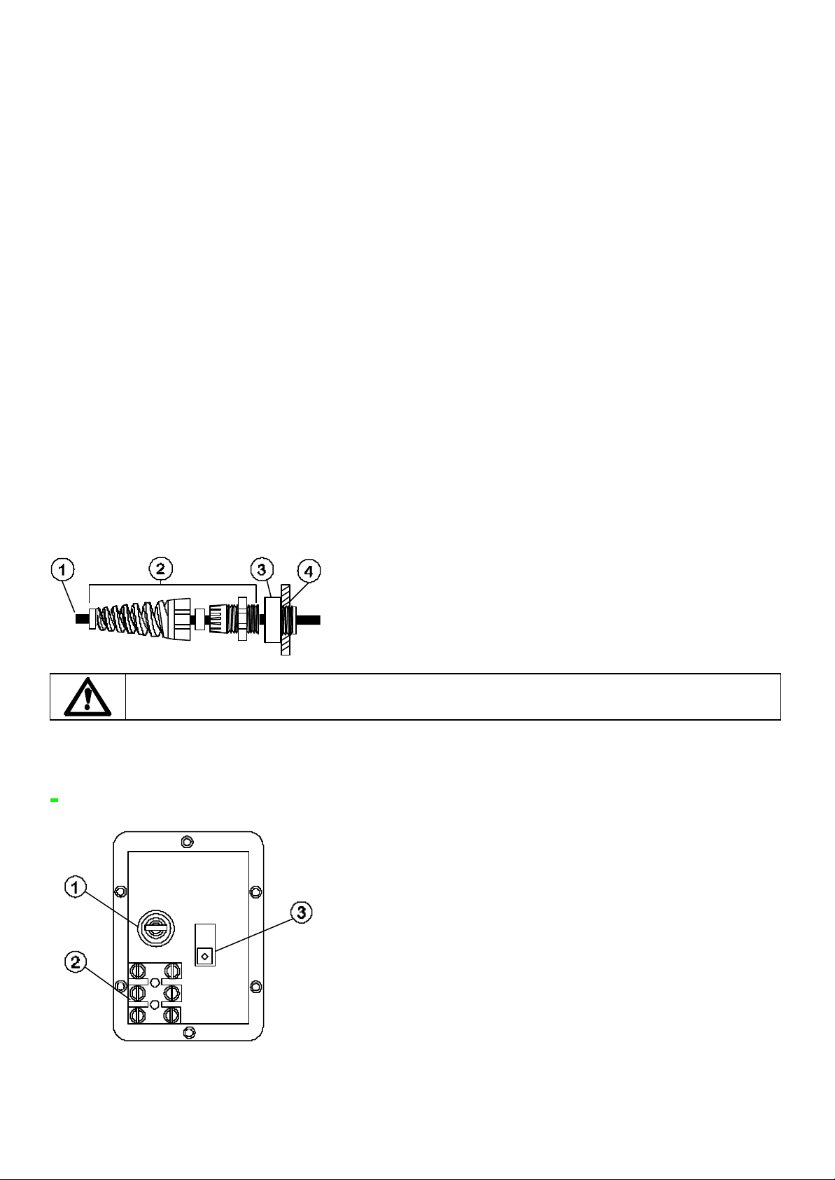
• Remove the small transparent plate on the rear panel to gain access to the voltage selector and terminal block.
• Set the voltage selector switch to either 120V for 100-120V 50/60Hz single phase AC supplies or 240V for 220-240V 50/60Hz
single phase AC supplies.
• Route the mains supply cable through the entry point to the right of the recess and couple the cable to the terminal block as
shown on the rear panel.
• The cable entry accepts three core 0.75 square millimetre PVC sheathed mains cable (via the screw adaptor supplied) so
that a mains lead can be used.
• Ensure that the mains lead is securely retained in the strain relief gland so that IP55 ingress protection is maintained.
• Securely replace the transparent plate and the gasket over the recess.
1 Power cable 5-8mm O.D. (outside diameter)
2 Strain relief gland SL 0020
3 Adaptor MR0678T
4 M20 Conduit thread for direct conduit connection, through back panel
Ingress protection standard will be compromised if fittings are not correctly replaced.
Rear panel recess
The pump rear panel recess houses the following:
1 Fuse holder 2 Terminal block 3 Voltage selection switch
Troubleshooting
Should the unit fail to operate, make the following checks to determine whether or not servicing is required.
3
Page 4

• Check that the power switch is on.
• Check the mains supply is available at the pump unit.
• Check the voltage selector switch is in the correct position.
• Check the fuse in the mains socket.
• Check that the pump is not stalled by incorrect fitting of tubing.
Manual operation
• Start up direction Start the pump by turning the Forward/Off/Reverse switch to the required direction of rotation. The
preferred direction of rotation is clockwise (with fluid entering at the bottom of the right of the pumphead), which will ensure
the longest possible tube life. To operate against higher pressures, use anticlockwise rotation.
• Prime To prime the pump at maximum speed turn the Auto/Manual/Max switch on the front panel to its Max position.
When released the switch will return to its Manual position.
• Speed control The speed setting dial is calibrated in percentage of maximum speed and has a locking knob to prevent
accidental speed changes.
• Stop Stop the pump by turning the Forward/Off/Reverse switch to its central Off position. To change the direction of flow,
turn the Forward/Off/Reverse switch to its central Off position until the pumphead rotor stops, and turn it to the required
direction of rotation.
If returning from auto control to manual control, it is not necesssary to disconnect the process signal from the pump or adjust the
calibration potentiometers.
Care and maintenance
The only scheduled maintenance of the pump unit is to inspect the motor brushes and to replace them before their length is less
than 10mm. The life of the brushes depends on the duty of the pump but is expected to be at least 4,000 hours at maximum
speed.
If the pump requires cleaning use a mild solution of detergent in water after removing the pumphead. Do not use strong solvents.
For gearbox rebuilds, use 15ml of the recommended lubricant RD-105. This is a SAE 30 mineral oil loaded with molybdenum
disulphide to form a soft fluid grease.
Specification
Maximum rotor speed 55rpm, 220rpm
Shaft torque 2.2Nm
Control range 100:1
Voltage/frequency 100-120/220-240V 50/60Hz
Power consumption 100VA
Operating temperature range 5C to 40C
Storage temperature range -40C to 70C
Noise <70dB(A) at 1m
Weight 8.0kg
Standards IEC 335-1, EN60529 (IP55)
Machinery Directive 98/37/EC EN60204-1
Low Voltage Directive 73/23/EEC EN61010-1
EMC Directive 89/336/EEC EN50081-1/EN50082-1
Specific drive performance details such as loaded drive speed variation against mains supply voltage fluctuation and drive
stability from a cold start to normal operating temperature are available on request. For further information please contact
Watson-Marlow Technical Support Department.
501RL Pumphead
The 501RL pumphead has two spring-loaded working rollers, which automatically compensate for minor variations in tubing
wall thickness, giving extended tube life. The 501RL is set during manufacture to accept tubing with wall thicknesses of between
1.6mm and 2.0mm, and internal diameters of up to 8.0mm. It is equipped with a "tool lockable" guard for increased safety. This
should be locked shut whilst the pump is in use.
The pumphead can be run clockwise for extended tube life, or anti-clockwise to operate against higher pressures.
Flow rates
Flow rates for the 504S were obtained using silicone tubing with the pumphead rotating clockwise, pumping water at 20C with
zero suction and delivery pressures. For critical applications determine flow rates under operating conditions.
4
Page 5

Installation
Remove the grub screws on the drive front panel to enable the pumphead to be fitted.
Fit the track in any one of three orientations, over the drive shaft and locating boss. Secure the track with the locating screw.
Ensure the drive shaft is degreased before locating the rotor onto the shaft via the split collet. Tighten the rotor screw to a torque
of 3Nm to prevent the collet slipping during operation.
To reposition the track, swing out the crank handle to expose the rotor retaining screw. Turn the screw anticlockwise one turn to
release the collet, and withdraw the rotor from the shaft. Loosen the track locating screw, and pull the track clear. Rotate the
track to its new position and tighten the track locating screw. Use this method of removal and fitting if cleaning is required.
Tube loading
Isolate pump from mains supply. Unlock and open the hinged guard and swing out the rotor crank handle until it locks into
position. Select the length of tubing required, noting that approximately 240mm is required for the track systems.
Fit one end of the tubing into one of the spring loaded clamps, and then, whilst rotating the rotor with the crank handle, feed the
tubing between the rollers and the track, aligning it within the rotor tube guides. The tubing must lie naturally against the track
and must not be twisted or stretched.
Fit the other end of the tubing into the second spring loaded clamp, ensuring that the tubing is not slack in the pumphead, since
this can reduce tube life.
Close the crank handle and shut and lock the guard.
After the pump has been started, open the delivery clamp for a short time, so that the tube can find its natural length.
The 501RL pumphead is fitted with four-position tube clamps, to accommodate various tube diameters, which can be adjusted
by pushing in or pulling out the bars at the top of the upper clamp and the bottom of the lower clamp. Set the clamps so that the
minimum necessary pressure is applied to the tubing.
5
Page 6
Roller adjustment
The 501RL has a factory set gap of 2.6mm between the rollers and the track and is suitable for tubing having wall thicknesses of
between 1.6 and 2.0mm. Adjustment of the gap will be required if tubing having a wall thickness of less than 1.6mm is required.
There is an adjusting screw on each of the two roller arms, and each of these screws will require adjustment. The correct gap is
twice the wall thickness less twenty percent. Correct adjustment is important: over occlusion will reduce tube life; under
occlusion will reduce pumping efficiency.
To change the gap setting, turn each adjusting screw clockwise to increase the gap, or anticlockwise to decrease the gap. A full
turn changes the gap by 0.8mm.To restore the original settings of 2.6mm, turn the adjusting screws until both rollers are just
touching the track, then tighten each screw by three and a quarter turns. The 501RL2 has a factory set gap of 3.8mm between
the wall and the track and is suitable for tubing having wall thickness of between 2.1 and 2.5mm.
Check moving parts of the rotor from time to time for freedom of movement. Lubricate pivot points and rollers occasionally with
Teflon lubricating oil.
Specific drive performance details such as loaded drive speed variation against mains supply voltage fluctuation and drive
stability from a cold start to normal operating temperature are available on request. For further information please contact
Watson-Marlow Technical Support Centre.
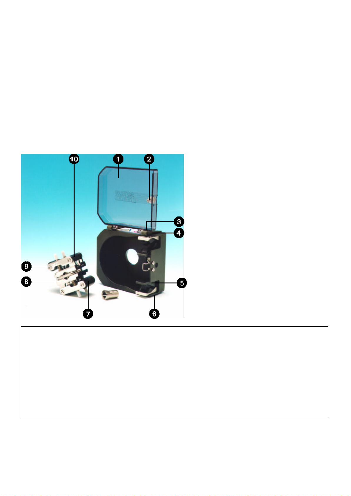
Pumphead spares
Number Spare Description
1 MN 1200M Lockable guard
2 FN 4502 Lock
3 FN 2341 Hinge screw
4 MN 0266M Hinge grey
5 MNA0623A Tube clamp assembly
6 FN 2332 Screw
7 MN 0011T Main roller
8 MNA0143A 501RL Rotor Assembly
9 SG0001/SG0002 Springs standard/hard
10 MN 0012T Follower roller
XX 0095 Teflon lubricant
6
Page 7

Drive spares
Number Spare Spare 12-24V Description
1 GR 0028 GR 0028 Cable gland
2 FH 0007 FH 0010 Fuse holder
3 FS 0003 FS 0043 Fuse 1A T type glass
4 MR 0669S MR 0669S Window cover
5 MR 0771S MR 0771S Window gasket
6 MN 0488S MN 0488S Front/rear panel gasket
7 MN 0487S MN 0487S Top/bottom case gasket
8 BM 0014 BM 0012 Motor brush
9 MNA0388A Geared motor 220rpm
9 MNA0396A Geared motor 55rpm
9 MNA0459A Geared motor 170rpm
10 MR 0769B MR 0769B Speed control potentiometer
12 MR 0751M MR 0751M Speed control knob
13 SW 0133 SW 0133 Max switch button
14 SW 0132 SW 0132 Off/direction switch
15 MNA0531A MNA0448A Control PCB
16 TF 0036 Transformer
7
Page 8

Outline dimensions
8
Page 9

#
English
English
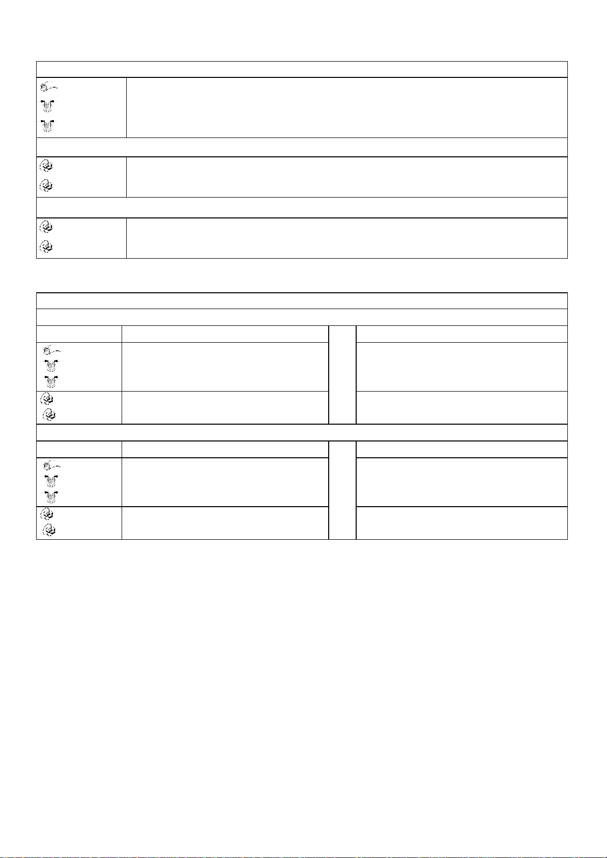
Tube number Tube bore Double-Y Maximum cassettes rpm
Pressure (+) Suction Clockwise (rpm) Anticlockwise (rpm) Stop
501RL, 501RL2 (ml/min)
Flow rates
# 112 13 14 16 25 17 18
mm 0.5 0.8 1.6 3.2 4.8 6.4 8.0
" 1/50 1/32 1/16 1/8 3/16 1/4 5/16
55 2.3 6.7 24 100 220 350 550
220 9.2 27 94 410 890 1400 2200
505L (ml/min)
Flow rates
# 14 16 25 17 18 122
mm 1.6 3.2 4.8 6.4 8.0 9.6
" 1/16 1/8 3/16 1/4 5/16 3/8
55 40 125 230 385 495 685
220 155 500 925 1540 1980 2750
505BA (ml/min)
Flow rates
mm
"
55 0.027 0.07 0.16 0.27 0.44 0.79 1.155
170 0.082 0.22 0.50 0.83 1.36 2.45 3.57 48
mm
"
55 1.54 2.04 2.57 3.22 3.82 4.14 4.37
170 4.76 6.29 7.75 9.96 11.8 12.8 13.5 48
mm
"
55 5.05 6.30 7.60 9.84 11.0 12.84
170 15.6 19.5 23.5 30.4 34.0 39.7 48
: < 170
0.13
0.005
0.88
0.035
1.65
0.065
0.19
0.007
1.02
0.04
1.85
0.07
0.25
0.01
1.14
0.045
2.05
0.08
0.38
0.015
1.29
0.05
2.38
0.09
0.50
0.02
1.42
0.055
2.54
0.1
0.63
0.025
1.47
0.058
2.79
0.11
0.76
0.03
1.52
0.06
9
Page 10
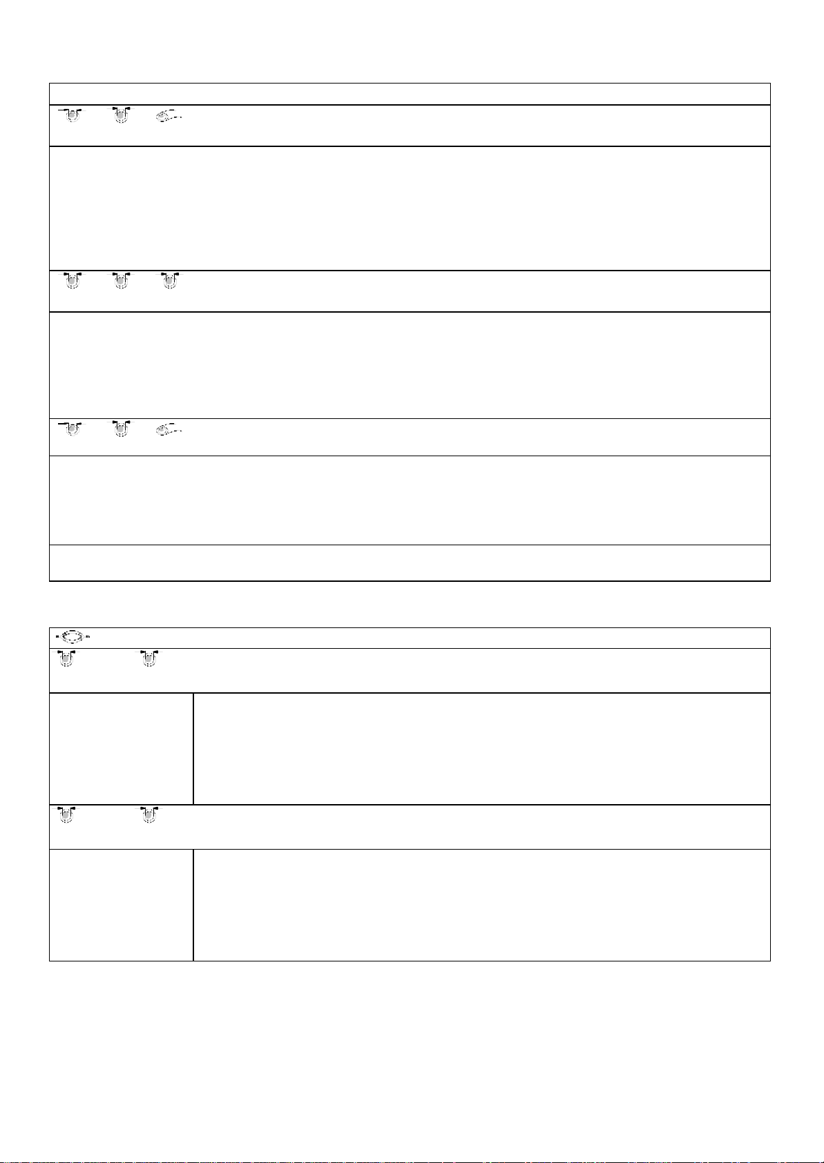
313/314 (ml/min)
Flow rates
# 112 13 14 16 25 17 18
mm 0.5 0.8 1.6 3.2 4.8 6.4 8.0
" 1/50 1/32 1/16 1/8 3/16 1/4 5/16
313
55 1.5 3.9 15 55 121 198 275
220 6.6 15 60 220 484 792 1100
314
55 1.5 3.3 13 46 104 165 220
220 6.6 13 55 186 418 660 880
313
Maximum number of pumpheads
313/314 Peroxide/ Platinum Silicone
(0 = bar = 0.5) (0.5 = bar = 2.0)
313/314 Marprene, Tygon, Neoprene, Viton
# 112 13 14 16 25 17 18 112 13 14 16 25 17 18
mm 0.5 0.8 1.6 3.2 4.8 6.4 8.0 0.5 0.8 1.6 3.2 4.8 6.4 8.0
" 1/50 1/32 1/16 1/8 3/16 1/4 5/16 1/50 1/32 1/16 1/8 3/16 1/4 5/16
55 6 6 6 6 6 4 3 6 6 6 6 5 3 3
220 6 6 6 6 6 4 3 6 6 6 6 5 3 3
(0 = bar = 0.5) (0.5 = bar = 2.0)
# 112 13 14 16 25 17 18 112 13 14 16 25 17 18
mm 0.5 0.8 1.6 3.2 4.8 6.4 8.0 0.5 0.8 1.6 3.2 4.8 6.4 8.0
" 1/50 1/32 1/16 1/8 3/16 1/4 5/16 1/50 1/32 1/16 1/8 3/16 1/4 5/16
55 6 6 6 6 5 3 3 6 6 6 6 4 3 3
220 6 6 6 6 5 3 3 6 6 6 6 4 3 3
10
Page 11
501RL, 501RLG, 313
Product codes
mm " # Peroxide Silicone Platinum Silicone Marprene Bioprene
0.5 1/50 112 910.0005.016 913.0005.016 902.0005.016 903.0005.016
0.8 1/32 13 910.0008.016 913.0008.016 902.0008.016 903.0008.016
1.6 1/16 14 910.0016.016 913.0016.016 902.0016.016 903.0016.016
3.2 1/8 16 910.0032.016 913.0032.016 902.0032.016 903.0032.016
4.8 3/16 25 910.0048.016 913.0048.016 902.0048.016 903.0048.016
6.4 1/4 17 910.0064.016 913.0064.016 902.0064.016 903.0064.016
8.0 5/16 18 910.0080.016 913.0080.016 902.0080.016 903.0080.016
mm " # STA-PURE* Gore fluroelastomer* Neoprene Tygon
0.8 1/32 13 920.0008.016
1.6 1/16 14 960.0016.016 965.0016.016 920.0016.016 950.0016.016
3.2 1/8 16 960.0032.016 965.0032.016 920.0032.016 950.0032.016
4.8 3/16 25 960.0048.016 965.0048.016 920.0048.016 950.0048.016
6.4 1/4 17 960.0064.016 965.0064.016 920.0064.016 950.0064.016
8.0 5/16 18 960.0080.016 960.0080.016 920.0080.016 950.0080.016
mm " # Fluorel Butyl **
1.6 1/16 14 970.0016.016 930.0016.016
3.2 1/8 16 970.0032.016 930.0032.016
4.8 3/16 25 970.0048.016 930.0048.016
6.4 1/4 17 970.0064.016 930.0064.016
8.0 5/16 18 970.0080.016 930.0080.016
* Use 501RLG
* *Not suitable for use with 313 pumpheads
501RL2, 501RL2G
Product codes
mm " Peroxide
Silicone
1.6 1/16 910.0016.024 913.0016.024 902.0016.024 903.0016.024 960.0016.024
3.2 1/8 910.0032.024 913.0032.024 902.0032.024 903.0032.024 960.0032.024
4.8 3/16 910.0048.024 913.0048.024 902.0048.024 903.0048.024 960.0048.024
6.4 ¼ 910.0064.024 913.0064.024 902.0064.024 903.0064.024 960.0064.024
8.0 5/16 910.0080.024 913.0080.024 902.0080.024 903.0080.024 960.0080.024
9.6 3/8 910.0096.024 913.0096.024 902.0096.024 903.0096.024
mm " Gore
fluoroelastomer*
1.6 1/16
3.2 1/8 965.0032.024
4.8 3/16 965.0048.024
6.4 ¼ 965.0064.024
8.0 5/16 965.0080.024
9.6 3/8
* Use 501RL2G
965.0016.024
Platinum
Silicone
Marprene Bioprene STA-PURE*
11
Page 12

505L, 505LG
(2.4mm) Product codes
mm "
#
1.6 1/16 119 910.E016.024 913.E016.024 902.E016.024 960.E032.K24 965.E032.K24
3.2 1/8 120 910.E032.024 913.E032.024 902.E032.024 960.E032.K24 965.E032.K24
4.8 3/16 15 910.E048.024 913.E048.024 902.E048.024 960.E048.K24 965.E048.K24
6.4 ¼ 24 910.E064.024 913.E064.024 902.E064.024 960.E064.K24 965.E064.K24
8.0 5/16 121 910.E080.024 913.E080.024 902.E080.024 960.E080.K24 965.E080.K24
9.6 3/8 122 910.E096.024 913.E096.024 902.E096.024
9.6 3/8 122 910.H096.024 (high flow element)
Peroxide
Silicone
Platinum
Silicone
Marprene STA-PURE Gore
fluoroelastomer
501RL
Flow rates
Watson-Marlow, Bioprene and Marprene are trademarks of Watson-Marlow Limited.
Tygon is a trademark of the Saint Gobain Performance Plastics Company.
Warning, These products are not designed for use in, and should not be used for patient connected applications.
The information contained in this document is believed to be correct but Watson-Marlow Limited accepts no liability for any
errors it contains, and reserves the right to alter specifications without notice.
12
Page 13

Product use and decontamination declaration
In compliance with the UK Health & Safety at Work Act and the Control of Substances Hazardous to Health
Regulations you, the user are required to declare the substances which have been in contact with the product(s) you
are returning to Watson-Marlow or any of its subsidiaries or distributors. Failure to do so will cause delays in servicing
the product. Therefore, please complete this form to ensure that we have the information before receipt of the
product(s) being returned. A FURTHER COPY MUST BE ATTACHED TO THE OUTSIDE OF THE PACKAGING
CONTAINING THE PRODUCT(S). You, the user, are responsible for cleaning and decontaminating the product(s)
before returning them.
Please complete a separate Decontamination Certificate for each pump returned. RGA No: …………………...
1 Company
Address ………...................................................................Postcode ………………………………………
Telephone ……………………………………………. .................Fax Number …………………………………..
2.1 Serial Number … … … … … … … … … … … … … ........... (a)………………………………………………….
2.2 Has the Product been used? (b)…………………………………………………
YES NO (c)…………………………………………………
(d)…………………………………………………
If yes, please complete all the following Sections. If no, please complete Section 5 only
3 Details of substances pumped
3.1 Chemical names:
(a)………………..........................
(b)…………….............................
(c)………………..........................
(d)…………….............................
3.2 Precautions to be taken in handling these substances: To assist servicing, please describe any fault
(a)………… .................................................... condition(s) you have witnessed
(b)………… ................................................... …………………………………………………
(c) ………………............................................... ……………………………………………………………
(d)………………................................................ ……………………………………………………………
3.3 Action to be taken in the event of human contact: ……………………………………………………………………………………………………
(a)…………………………………………………………………. ……………………………………………………………
(b)…………………………………………………………………. ……………………………………………………………
(c)………….……………………………………………………… ……………………………………………………………
(d)………….……………………………………………………… ……………………………………………………………
3.4 Cleaning fluid to be used if residue of chemical is found: ……………………………………………………………
(a)…………………………………………………………………. ……………………………………………………………
(b)…………………………………………………………………. ……………………………………………………………
(c)………….……………………………………………………… ……………………………………………………………
(d)………….……………………………………………………… ……………………………………………………………
4 I hereby confirm that the only substances(s) that the equipment specified has
pumped or come into contact with are those named, that the information given is
correct, and the carrier has been informed if the consignment is of a hazardous
nature.
5 Signed …………………………………………………………………………………
Name …………………………………………………………………………………
Position ……………………………………………………………………………….
Date …………………………………………………………………………………..
Watson-Marlow Bredel Pumps . Falmouth . Cornwall TR11 4RU . England . Tel: 01326 370370 . Fax: 01326 376009
13
 Loading...