


INSTALLATION & OPERATION MANUAL HEAVY DUTY ELECTRIC GRIDDLES
MODELS
HEG24E
HEG36E
HEG48E
HEG60E
HEG72E
HEG36E
WEG24E
WEG36E
WEG48E
WEG60E
WEG72E
|
WEG36E |
©ITW Food Equipment Group, LLC |
RETAIN THIS MANUAL FOR FUTURE USE |
3600 North Point Blvd. |
FORM F-38341 (3-14) |
Baltimore, MD 21222 |

TABLE OF CONTENTS
INSTALLATION……………………………………………………………………………………… 3
Installation Codes And Standards…………………………………………………………… 3
Unpacking………………………………………………………………………………………… 3
Leg Assembly……………………………………………………………………………………. 3
Leveling…………………………………………………………………………………………… 4
Location…………………………………………………………………………………………… 4
Electrical Connections…………………………………………………………………………. 4
Phase Wiring Connections……………………………………………………………………. 5
Electrical Data…………………………………………………………………………………… 6
OPERATION………………………………………………………………………………………….. 6
Before First Use…………………………………………………………………………………. 6
Seasoning The Griddle………………………………………………………………………… 7
Controls…………………………………………………………………………………………… 7
Using The Griddle………………………………………………………………………………. 7
Zone Cooking……..……………………………………………………………………………. 8
Cleaning The Griddle…………………………………………………………………………... 9
HEG And WEG Griddle Plate…………………………………………………………………. 9
SHUTDOWN ………………..……………………………………………..………………………… 10
EXTENDED SHUTDOWN …………………………………………………………………………. 10
MAINTENANCE……………………………………………………………………………………… 10
Service And Parts Information……………………………………………………………….. 10
TROUBLESHOOTING………………………………………………………………………………. 11
ACCESSORY INSTALLATION……………………………………………………………………. 12
- 2 -

INSTALLATION, OPERATION AND CARE OF HEAVY DUTY ELECTRIC GRIDDLES
GENERAL
Heavy Duty Electric Griddles are produced with quality workmanship and materials. Proper installation, usage and maintenance of your griddle will result in many years of satisfactory performance. Thoroughly read this entire manual and carefully follow all of the instructions provided.
INSTALLATION
Before installing, check the electrical service to make sure it agrees with the specifications on the rating plate. If the supply and equipment voltages do not agree, do not proceed with the installation. Contact your dealer or Vulcan immediately.
INSTALLATION CODES AND STANDARDS
Your Vulcan griddle must be installed in accordance with:
In the United States of America:
1.State and local codes
2.National Electrical Code ANSI/NFPA – 70 (latest edition) available from The National Fire Protection Association,1 Batterymarch Park,Quincy, MA 02269.
3.NFPA Standard #96 Vapor Removal from Cooking Equipment, (latest edition) available From the National Fire Protection Association,Batterymarch Park, Quincy, MA 02269.
In Canada:
1.Local code
2.Canadian Electrical Code C22.1 Part 1 (latest edition) available from the Canadian Standard Association, 5060 Spectrum Way, Suite 100, Mississauga, Ontario, Canada, L4W 5N6.
UNPACKING
This griddle was inspected before leaving the factory. The transportation company assumes full responsibility for safe delivery upon acceptance of shipment. Check for possible shipping damage immediately after unpacking. If the griddle is found to be damaged, save the packaging material and contact the carrier within 15 days of delivery.
LEG ASSEMBLY
Attach the legs to the body by threading the exposed leg stud into the threaded holes located on the underside of the unit. Tighten each leg so that the top face of the leg is pressed firmly against the body bottom. Do not operate griddle without legs or integrated stand as damage will occur.
- 3 -

LEVELING
Position the griddle in the desired location. Level the griddle by using a wrench to turn the adjustable feet. You must hold the leg while turning the foot so that it’s attachment to the griddle is not loosened.
LOCATION
The installation location must be kept free and clear of combustibles. Do not permit air to blow directly at the griddle. Avoid open windows next to the griddle wherever possible. Avoid wall-type fans which create air cross-currents within the room.
This griddle is Design Certified for installation on a non-combustible counter with 4” legs, or combustible floor with 24” high stand.
INSTALLATION CLEARANCES |
|
|
|
COMBUSTIBLE CONSTRUCTION |
NON-COMBUSTIBLE CONSTRUCTION |
Back: |
1” |
0” |
Right |
1” |
0” |
Left Side |
1” |
0” |
ELECTRICAL CONNECTIONS
 Electrical and grounding connections must comply with the applicable portions of the National Electrical Code and/or other local electrical codes.
 Disconnect the electrical power to the griddle and follow lockout / tagout procedures.
Electrical Connections
1.Remove the junction box cover plate(s) at the back of the unit. This exposes the built-in junction boxes and griddle line leads.
2.Select a suitable knockout on the rear or bottom of the junction box.
3.Connect the griddle’s line leads to the supply wires with factory supplied wire connectors as shown in the applicable wiring instructions. Do not disturb the internal griddle wiring.
4.Push the excess wire into the junction box and replace the cover plate. Never operate the griddle without the junction box covers in place.
 Since the griddle is not fused, you must connect it to a fused circuit equipped with a suitable disconnecting means as required by local authorities.
- 4 -

Phase Wiring Connections |
|
|
||
HEG24E/WEG24E |
HEG60E/WEG60E |
|||
208,240 & 480 VAC 3-PHASE WIRING CONNECTIONS: |
208,240 & 480 VAC 3-PHASE WIRING CONNECTIONS: |
|||
|
1. CONNECT WIRE #5 TO “L1” |
LEFT JUNCTION BOX |
||
|
2. CONNECT WIRE #6 & #11 TO “L2” |
1. CONNECT WIRE #18 TO “L1” |
||
|
3. CONNECT WIRE #10 TO “L3” |
2. CONNECT WIRE #16 TO “L2” |
||
|
|
3. CONNECT WIRE #15 TO “L3” |
||
208 & 240 VAC 1-PHASE WIRING CONNECTIONS: |
RIGHT JUNCTION BOX |
|||
|
|
1. CONNECT WIRE #8 & #10 TO “L1” |
||
|
1. CONNECT WIRE #5 & #10 TO “L1” |
2. CONNECT WIRE #17 TO “L2” |
||
|
2. CONNECT WIRE #6 & #11 TO “L2” |
3. CONNECT WIRE #12 TO “L3” |
||
|
|
208 & 240 VAC 1-PHASE WIRING CONNECTIONS: |
||
|
|
LEFT JUNCTION BOX |
||
|
|
1. CONNECT WIRE #15 & #16 TO “L1” |
||
HEG36E/WEG36E |
2. CONNECT WIRE #18 TO “L2” |
|||
RIGHT JUNCTION BOX |
||||
|
|
|||
208,240 & 480 VAC 3-PHASE WIRING CONNECTIONS: |
1. CONNECT WIRE #10 & #12 TO “L1” |
|||
|
|
2. CONNECT WIRE #8 & #17 TO “L2” |
||
|
1. CONNECT WIRE #10 TO “L1” |
|
|
|
|
2. CONNECT WIRE #11 TO “L2” |
|
|
|
|
|
|
||
|
3. CONNECT WIRE #5 & #6 TO “L3” |
|
|
|
208 & 240 VAC 1-PHASE WIRING CONNECTIONS: |
HEG72E/WEG72E |
|||
|
1. CONNECT WIRE #5 & #10 TO “L1” |
|||
|
208,240 & 480 VAC 3-PHASE WIRING CONNECTIONS: |
|||
|
2. CONNECT WIRE #6 & #11 TO “L2” |
|||
|
|
LEFT JUNCTION BOX |
||
|
|
1. CONNECT WIRE #16 & #11 TO “L1” |
||
|
|
2. CONNECT WIRE #15 TO “L2” |
||
|
|
3. CONNECT WIRE #18 TO “L3” |
||
HEG48E/WEG48E |
RIGHT JUNCTION BOX |
|||
|
|
1. CONNECT WIRE #8 & #10 TO “L1” |
||
208,240 & 480 VAC 3-PHASE WIRING CONNECTIONS: |
2. CONNECT WIRE #17 TO “L2” |
|||
|
|
3. CONNECT WIRE #19 TO “L3” |
||
|
1. CONNECT WIRE #10 & #11 TO “L1” |
|
|
|
|
2. CONNECT WIRE #8, #9 & #13 TO “L2” |
208 & 240 VAC 1-PHASE WIRING CONNECTIONS: |
||
|
3. CONNECT WIRE #12 TO “L3” |
|||
|
|
LEFT JUNCTION BOX |
||
208 & 240 VAC 1-PHASE WIRING CONNECTIONS: |
1. CONNECT WIRE #11 & #18 TO “L1” |
|||
|
|
2. CONNECT WIRE #16 & #15 TO “L2” |
||
|
1. CONNECT WIRE #8, #12 & #13 TO “L1” |
RIGHT JUNCTION BOX |
||
|
2. CONNECT WIRE #9, #10 & #11 TO “L2” |
|||
|
|
1. CONNECT WIRE #10 & #19 TO “L1” |
||
|
|
2. CONNECT WIRE #8 & #17 TO “L2” |
||
- 5 -

Electrical Data
STANDARD VOLTAGES 208 VOLTS OR 240 VOLTS 50/60 Hz. SINGLE OR THREE PHASE
480 VOLTS 50/60 Hz. THREE PHASE ONLY
|
TOTAL |
TOTAL |
3 PHASE LOADING |
|
|
|
|
|
NOMINAL AMPS PER LINE WIRE CONN. |
|
|
||||||||||||
MODEL NUMBER |
CONN. |
KW |
KW PER PHASE |
|
|
|
|
|
|
3 PHASE |
|
|
|
|
|
|
1 PHASE |
||||||
|
KW |
PER |
PER CONN.* |
|
|
208 VOLT |
|
|
240 VOLT |
|
|
480 VOLT |
|
208 |
240 |
||||||||
|
|
CONN |
X Y |
Y Z |
|
X Z |
X |
|
Y |
|
Z |
X |
|
Y |
|
Z |
X |
|
Y |
|
Z |
VOLT |
VOLT |
HEG24E/WEG24E |
10.8 |
10.8 |
5.4 |
5.4 |
|
0.0 |
22.5 |
|
45.0 |
|
22.5 |
19.5 |
|
39.0 |
|
19.5 |
9.7 |
|
19.5 |
|
9.7 |
51.9 |
45.0 |
HEG36E/WEG36E |
16.2 |
16.2 |
5.4 |
5.4 |
|
5.4 |
45.0 |
|
45.0 |
|
45.0 |
39.0 |
|
39.0 |
|
39.0 |
19.5 |
|
19.5 |
|
19.5 |
77.9 |
67.5 |
HEG48E/WEG48E |
21.6 |
21.6 |
10.8 |
5.4 |
|
5.4 |
67.4 |
|
67.4 |
|
45.0 |
58.5 |
|
58.5 |
|
39.0 |
29.2 |
|
29.2 |
|
19.5 |
103.8 |
90.0 |
HEG60E/WEG60E** |
27.0 |
16.2 |
5.4 |
5.4 |
|
5.4 |
45.0 |
|
45.0 |
|
45.0 |
39.0 |
|
39.0 |
|
39.0 |
19.5 |
|
19.5 |
|
19.5 |
77.9 |
67.5 |
|
|
10.8 |
5.4 |
0.0 |
|
5.4 |
45.0 |
|
22.5 |
|
22.5 |
39.0 |
|
19.5 |
|
19.5 |
19.5 |
|
9.7 |
|
9.7 |
51.9 |
45.0 |
HEG72E/WEG72E* |
32.4 |
16.2 |
5.4 |
5.4 |
|
5.4 |
45.0 |
|
45.0 |
|
45.0 |
39.0 |
|
39.0 |
|
39.0 |
19.5 |
|
19.5 |
|
19.5 |
77.9 |
67.5 |
|
|
16.2 |
5.4 |
5.4 |
|
5.4 |
45.0 |
|
45.0 |
|
45.0 |
39.0 |
|
39.0 |
|
39.0 |
19.5 |
|
19.5 |
|
19.5 |
77.9 |
67.5 |
*NOTE: Two separate conduit connections must be made: each connection carries one-half of the rated load.
**NOTE: Two separate conduit connections must be made: one connection carries 16.2 KW, the other connection carries 10.8 KW.
OPERATION
 The griddle and its parts are hot. Use care when operating, cleaning or servicing the griddle.
 Disconnect power supply and follow lockout / tagout procedures before cleaning and servicing the appliance.
BEFORE FIRST USE
Remove all packing material and protective plastic from the surfaces of the unit. Before leaving the factory the griddle cooking surface is coated with vegetable oil as a rust inhibitor. Remove this film when the griddle plate is being cleaned prior to its first cooking use. Heat the griddle to 200-300°F to loosen and melt the coating, then clean the surface by adding water or a non-corrosive, grease dissolving commercial cleaner, following the manufacturer’s directions. Scrape the oil residue from the plate with a griddle scraper. Rinse thoroughly and wipe dry with a soft clean cloth. Clean all accessories.
- 6 -
SEASONING THE GRIDDLE
Season the griddle to avoid possible surface corrosion before first use, and after every cleaning. This will also help reduce the sticking of cooked food product. Heat griddle to a low temperature (300-350°F) and apply a small amount of cooking oil – about one ounce per square foot of surface. Use a soft lint-free cloth to spread the oil over the entire griddle surface to create a thin film. Wipe off any excess oil with a cloth. Repeat the procedure until the griddle has a slick, mirror-like finish.
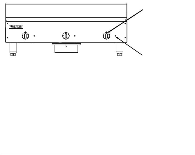
CONTROLS
Each thermostat independently controls a 12” wide griddle section. When each thermostat is turned ON, the corresponding red indicator light will illuminate to indicate that the elements are on for that section. When the griddle plate reaches the desired temperature set point, the elements will be turned off for that section and the indicator light will go off. Indicator lights will cycle off and on as the thermostats turn the corresponding heating elements off and on to maintain the set temperatures. At the end of each day, you must turn all thermostat knobs to the OFF position to turn off the unit.
Thermostat Knob
Red Indicator Light
USING THE GRIDDLE
To preheat, set the thermostats for the desired temperatures 20 minutes before cooking.
A uniform and systematic approach to loading the griddle will produce the most consistent product results.
- 7 -

ZONE COOKING
This griddle features two tubular heating elements in each 12” section Each section is controlled by an independent thermostat. Each 12” section is a separate cooking zone, and allows cooking a wide variety of products over a single griddle plate. The chart below is a suggested usage of zone cooking.
When zone cooking, it is suggested that you start with your lowest temperature setting at either side of the griddle, increasing the zone temperature as you move up the zone line. These zone cooking guidelines will vary depending on product temperatures, size and shape. This guide should be adjusted to suit your product and operational cooking preference.
HEG48E/WEG48E
ZONE 1 |
ZONE 2 |
|
ZONE 3 |
ZONE 4 |
|
(300°F) |
(350°F) |
|
(350°F) |
(400°F) |
|
|
|
|
|
|
|
PRODUCT |
|
PRODUCT |
PRODUCT |
||
Sausage |
Pancakes |
|
Omelet |
Steak (Rare) |
|
Eggs (Hard Fried) |
|
Stir Fry |
|||
French Toast |
|
Hash Browns |
|||
Eggs (Scrambled) |
|
Vegetables |
|||
Bacon |
|
Canadian Bacon |
|||
Burger (Well Done) |
|
Salmon |
|||
Eggs (Sunny Side Up) |
|||||
Steak (Well Done) |
Fish Cakes |
||||
Boiled Ham |
|
|
|||
Chicken Breast |
|
|
Lobster |
||
Steak (Medium Well) |
|||||
Frozen Foods |
Scampi |
||||
Fresh Burger (Medium Well) |
|||||
Pork Chops |
|
||||
Small Frozen Burger (Medium Well) |
|
||||
|
|
||||
|
|
|
|
|
|
- 8 -

CLEANING THE GRIDDLE
 The griddle and its parts are hot. Use care when operating, cleaning or servicing the griddle.
Clean the griddle regularly. A clean griddle always looks better, lasts longer and performs better. To produce evenly cooked, perfectly browned griddle products keep the griddle plate clean and free of carbonized grease. Carbonized grease on the surface hinders the transfer of heat from the griddle surface to the food, resulting in spotty browning and loss of cooking efficiency. Carbonized grease tends to cling to griddle foods, giving them a highly unsatisfactory and unappetizing appearance.
 Do not use a water-jet to clean the griddle as this can cause damage to internal electrical components.
The standard HEG and WEG griddle plates are carbon steel, but can be scored or dented by careless use of a spatula or scraper. Be careful not to dent, scratch, or gouge the plate surface. Do not try to knock off loose food that may be on the spatula by tapping the corner or the edge of the spatula on the griddle surface.
Clean the griddle surface thoroughly. Use a griddle stone, screen, or Scotch Bright pad on the surface as necessary. Rub with the grain of the metal while the griddle is still warm (not hot). A detergent may be used on the plate surface to help clean it, but be sure the detergent is thoroughly removed by flushing with clear water. After removal of detergent the surface of the plate the griddle should be seasoned according to the instructions in this manual.
AFTER EACH USE
Clean the griddle with a griddle scraper during the work shift. Take care not to vigorously strike the back or side splashes with the scraper.
ONCE PER DAY
Thoroughly clean the griddle back splash, sides and front. Turn the griddle off and allow it to cool down between 275°F-300°F, apply some water to the cooking surface and clean it with a griddle scraper. Remove, empty and wash the grease drawer in the same manner as an ordinary cooking utensil.
Wipe the griddle exterior clean with a damp cloth to prevent grease accumulation and dry.
- 9 -
 Loading...