


SERVICE MANUAL
HALF-SIZE
CONVECTION OVENS
ELECTRIC AND GAS
MODEL ML
ELECTRIC
ECO2D 114570
ECO2C 114572
GAS
GCO2D 114569
GCO2C 114571
GCO2D Shown
- NOTICE -
This Manual is prepared for the use of trained Vulcan Service Technicians and should not be used by those not properly qualified. If you have attended a Vulcan Service School for this product, you may be qualified to perform all the procedures described in this manual.
This manual is not intended to be all encompassing. If you have not attended a Vulcan Service School for this product, you should read, in its entirety, the repair procedure you wish to perform to determine if you have the necessary tools, instruments and skills required to perform the procedure. Procedures for which you do not have the necessary tools, instruments and skills should be performed by a trained Vulcan Service Technician.
Reproduction or other use of this Manual, without the express written consent of Vulcan-Hart, is prohibited.
A product of VULCAN-HART |
LOUISVILLE, KY 40201-0696 |
Form 24575 (12/96) |
|

HALF-SIZE CONVECTION OVENS |
|
TABLE OF CONTENTS |
|
GENERAL . . . . . . . . . . . . . . . . . . . . . . . . . . . . . . . . . . . . . . . . . . . . . . . . . . . . . . . . . . . . . . . . . . . . . . . . . . . . . |
3 |
Introduction . . . . . . . . . . . . . . . . . . . . . . . . . . . . . . . . . . . . . . . . . . . . . . . . . . . . . . . . . . . . . . . . . . . . . . . |
3 |
Specifications . . . . . . . . . . . . . . . . . . . . . . . . . . . . . . . . . . . . . . . . . . . . . . . . . . . . . . . . . . . . . . . . . . . . . |
3 |
Gas Ovens . . . . . . . . . . . . . . . . . . . . . . . . . . . . . . . . . . . . . . . . . . . . . . . . . . . . . . . . . . . . . . . . |
3 |
Electric Ovens . . . . . . . . . . . . . . . . . . . . . . . . . . . . . . . . . . . . . . . . . . . . . . . . . . . . . . . . . . . . . |
3 |
Tools . . . . . . . . . . . . . . . . . . . . . . . . . . . . . . . . . . . . . . . . . . . . . . . . . . . . . . . . . . . . . . . . . . . . . . . . . . . . |
3 |
REMOVAL AND REPLACEMENT OF PARTS . . . . . . . . . . . . . . . . . . . . . . . . . . . . . . . . . . . . . . . . . . . . . . . . . |
4 |
Covers and Panels . . . . . . . . . . . . . . . . . . . . . . . . . . . . . . . . . . . . . . . . . . . . . . . . . . . . . . . . . . . . . . . . . |
4 |
Control Panel Components . . . . . . . . . . . . . . . . . . . . . . . . . . . . . . . . . . . . . . . . . . . . . . . . . . . . . . . . . . . |
5 |
Blower And/or Blower Motor . . . . . . . . . . . . . . . . . . . . . . . . . . . . . . . . . . . . . . . . . . . . . . . . . . . . . . . . . . . |
6 |
Oven Door . . . . . . . . . . . . . . . . . . . . . . . . . . . . . . . . . . . . . . . . . . . . . . . . . . . . . . . . . . . . . . . . . . . . . . . . |
7 |
Door Switch . . . . . . . . . . . . . . . . . . . . . . . . . . . . . . . . . . . . . . . . . . . . . . . . . . . . . . . . . . . . . . . . . . . . . . . |
8 |
Heat Exchanger (Gas Ovens) . . . . . . . . . . . . . . . . . . . . . . . . . . . . . . . . . . . . . . . . . . . . . . . . . . . . . . . . . |
8 |
Burner (Gas Ovens) . . . . . . . . . . . . . . . . . . . . . . . . . . . . . . . . . . . . . . . . . . . . . . . . . . . . . . . . . . . . . . . . . |
9 |
Gas Valve (Gas Ovens) . . . . . . . . . . . . . . . . . . . . . . . . . . . . . . . . . . . . . . . . . . . . . . . . . . . . . . . . . . . . . . |
9 |
Heating Elements (Electric Ovens) . . . . . . . . . . . . . . . . . . . . . . . . . . . . . . . . . . . . . . . . . . . . . . . . . . . . |
10 |
SERVICE PROCEDURES AND ADJUSTMENTS . . . . . . . . . . . . . . . . . . . . . . . . . . . . . . . . . . . . . . . . . . . . . . |
11 |
Temperature Probe Test (All Models) . . . . . . . . . . . . . . . . . . . . . . . . . . . . . . . . . . . . . . . . . . . . . . . . . . |
11 |
Verification of Spark at Spark Probe . . . . . . . . . . . . . . . . . . . . . . . . . . . . . . . . . . . . . . . . . . . . . . . . . . . |
11 |
Gas Pressure Adjustment . . . . . . . . . . . . . . . . . . . . . . . . . . . . . . . . . . . . . . . . . . . . . . . . . . . . . . . . . . . |
12 |
Spark Ignition Control Test . . . . . . . . . . . . . . . . . . . . . . . . . . . . . . . . . . . . . . . . . . . . . . . . . . . . . . . . . . |
12 |
Electronic Control . . . . . . . . . . . . . . . . . . . . . . . . . . . . . . . . . . . . . . . . . . . . . . . . . . . . . . . . . . . . . . . . . |
13 |
Solid State Control Test . . . . . . . . . . . . . . . . . . . . . . . . . . . . . . . . . . . . . . . . . . . . . . . . . . . . . . . . . . . . . |
14 |
Solid State Control Calibration . . . . . . . . . . . . . . . . . . . . . . . . . . . . . . . . . . . . . . . . . . . . . . . . . . . . . . . . |
14 |
Door Switch Adjustment . . . . . . . . . . . . . . . . . . . . . . . . . . . . . . . . . . . . . . . . . . . . . . . . . . . . . . . . . . . . . |
15 |
Door Reversal . . . . . . . . . . . . . . . . . . . . . . . . . . . . . . . . . . . . . . . . . . . . . . . . . . . . . . . . . . . . . . . . . . . . |
16 |
Door Adjustment . . . . . . . . . . . . . . . . . . . . . . . . . . . . . . . . . . . . . . . . . . . . . . . . . . . . . . . . . . . . . . . . . . |
17 |
Blower Adjustment . . . . . . . . . . . . . . . . . . . . . . . . . . . . . . . . . . . . . . . . . . . . . . . . . . . . . . . . . . . . . . . . . |
17 |
Element Test . . . . . . . . . . . . . . . . . . . . . . . . . . . . . . . . . . . . . . . . . . . . . . . . . . . . . . . . . . . . . . . . . . . . . |
17 |
ELECTRICAL OPERATION . . . . . . . . . . . . . . . . . . . . . . . . . . . . . . . . . . . . . . . . . . . . . . . . . . . . . . . . . . . . . . 18
Component Function . . . . . . . . . . . . . . . . . . . . . . . . . . . . . . . . . . . . . . . . . . . . . . . . . . . . . . . . . . . . . . . 18
Component Location . . . . . . . . . . . . . . . . . . . . . . . . . . . . . . . . . . . . . . . . . . . . . . . . . . . . . . . . . . . . . . . 19
Sequence of Operation . . . . . . . . . . . . . . . . . . . . . . . . . . . . . . . . . . . . . . . . . . . . . . . . . . . . . . . . . . . . . 20
Ignition Module . . . . . . . . . . . . . . . . . . . . . . . . . . . . . . . . . . . . . . . . . . . . . . . . . . . . . . . . . . . . 20
Gas Oven . . . . . . . . . . . . . . . . . . . . . . . . . . . . . . . . . . . . . . . . . . . . . . . . . . . . . . . . . . . . . . . . 20
Electric Oven . . . . . . . . . . . . . . . . . . . . . . . . . . . . . . . . . . . . . . . . . . . . . . . . . . . . . . . . . . . . . 23
Schematics Gas Ovens . . . . . . . . . . . . . . . . . . . . . . . . . . . . . . . . . . . . . . . . . . . . . . . . . . . . . . . . . . . . . 26
GCO2D . . . . . . . . . . . . . . . . . . . . . . . . . . . . . . . . . . . . . . . . . . . . . . . . . . . . . . . . . . . . . . . . . 26
GCO2C . . . . . . . . . . . . . . . . . . . . . . . . . . . . . . . . . . . . . . . . . . . . . . . . . . . . . . . . . . . . . . . . . 27
Wiring Diagram - Gas Ovens . . . . . . . . . . . . . . . . . . . . . . . . . . . . . . . . . . . . . . . . . . . . . . . . . . . . . . . . . 28
GCO2D . . . . . . . . . . . . . . . . . . . . . . . . . . . . . . . . . . . . . . . . . . . . . . . . . . . . . . . . . . . . . . . . . 28
GCO2C . . . . . . . . . . . . . . . . . . . . . . . . . . . . . . . . . . . . . . . . . . . . . . . . . . . . . . . . . . . . . . . . . 30
Schematic-Electric Ovens . . . . . . . . . . . . . . . . . . . . . . . . . . . . . . . . . . . . . . . . . . . . . . . . . . . . . . . . . . . 32
ECO2D . . . . . . . . . . . . . . . . . . . . . . . . . . . . . . . . . . . . . . . . . . . . . . . . . . . . . . . . . . . . . . . . . 32
ECO2C . . . . . . . . . . . . . . . . . . . . . . . . . . . . . . . . . . . . . . . . . . . . . . . . . . . . . . . . . . . . . . . . . 33
Wiring Diagram Electric Ovens . . . . . . . . . . . . . . . . . . . . . . . . . . . . . . . . . . . . . . . . . . . . . . . . . . . . . . . 34
ECO2D . . . . . . . . . . . . . . . . . . . . . . . . . . . . . . . . . . . . . . . . . . . . . . . . . . . . . . . . . . . . . . . . . 34
ECO2C . . . . . . . . . . . . . . . . . . . . . . . . . . . . . . . . . . . . . . . . . . . . . . . . . . . . . . . . . . . . . . . . . 36
TROUBLESHOOTING . . . . . . . . . . . . . . . . . . . . . . . . . . . . . . . . . . . . . . . . . . . . . . . . . . . . . . . . . . . . . . . . . . 38
Electric Ovens . . . . . . . . . . . . . . . . . . . . . . . . . . . . . . . . . . . . . . . . . . . . . . . . . . . . . . . . . . . . . . . . . . . . 38
Gas Ovens . . . . . . . . . . . . . . . . . . . . . . . . . . . . . . . . . . . . . . . . . . . . . . . . . . . . . . . . . . . . . . . . . . . . . . 39
© VULCAN 1996
2

HALF-SIZE CONVECTION OVENS - GENERAL
GENERAL
INTRODUCTION
General
This manual will cover half-size electric and gas convection ovens that use either a solid state control or an electronic control.
Procedures in this manual are applicable to both gas and electric ovens unless specified.
SPECIFICATIONS
GAS OVENS |
|
|
|
|
|
|
|
|
|
|
|
|
|
|
|
|
|
|
|
GAS DATA |
|
ELECTRICAL DATA |
|
|
|
|
|
|
|
|
|
|
|
INPUT BTU/HR |
MANIFOLD PRESSURE |
LOAD |
AMP/LINE |
||
|
|
|
|
|
|
(Watts) |
|
|
|
Natural |
Propane |
Natural |
Propane |
120V |
|
|
|
|
|||||
|
|
|
|
|
|
|
|
|
Single Oven |
2500 |
2500 |
3.5" W.C. |
10"W.C. |
950 |
8 |
|
|
|
|
|
|
|
|
|
Stacked Oven |
5000 |
5000 |
3.5" W.C |
10"W.C. |
1900 |
16 |
|
|
|
|
|
|
|
|
ELECTRIC OVENS |
|
|
|
|
|
|
|
|
|
|
|
||
|
|
|
|
|
|
|
|
|
|
|
|
|
|
|
|
|
|
|
|
|
NOMINAL AMPS PER LINE WIRE |
|
|||||
|
|
|
3-PHASE LOADING |
|
|
|
|
|
|
|
|
||
|
|
|
|
|
3 PHASE |
|
|
1 PHASE |
|||||
|
|
TOTAL |
(KW PER PHASE) |
|
|
|
|
||||||
|
|
KW |
|
|
|
|
|
|
|
|
|
|
|
|
|
|
|
|
|
208V |
|
|
240V |
|
208V |
240V |
|
|
|
|
|
|
|
|
|
|
|
||||
|
|
|
|
|
|
|
|
|
|
|
|
|
|
|
|
|
L1-L2 |
L2-L3 |
L1-L3 |
L1 |
L2 |
L3 |
L1 |
L2 |
L3 |
|
|
|
|
|
|
|
|
|
|
|
|
|
|
|
|
|
Single Oven |
5.5 |
2.5 |
0 |
3.0 |
22.9 |
10.4 |
12.5 |
19.9 |
9.0 |
10.9 |
26.5 |
23.0 |
|
|
|
|
|
|
|
|
|
|
|
|
|
|
|
Stacked |
11.0 |
5.0 |
0 |
6.0 |
45.8 |
20.8 |
25.0 |
39.7 |
18.0 |
21.7 |
52.9 |
45.9 |
|
Ovens |
|
|
|
|
|
|
|
|
|
|
|
|
|
|
|
|
|
|
|
|
|
|
|
|
|
|
TOOLS
•Standard set of hand tools
•VOM with AC current tester (Any VOM with a sensitivity of at least 20,000 ohms per volt can be used.)
•Temperature tester
•Manometer (Gas Ovens)
3

HALF-SIZE CONVECTION OVENS - REMOVAL AND REPLACEMENT OF PARTS
REMOVAL AND REPLACEMENT OF PARTS
COVERS AND PANELS
Right Side Panel
WARNING: DISCONNECT THE ELECTRICAL POWER TO THE MACHINE AT THE MAIN CIRCUIT BOX. PLACE A TAG ON THE CIRCUIT BOX INDICATING THE CIRCUIT IS BEING SERVICED.
WARNING: SHUT OFF THE GAS BEFORE SERVICING THE UNIT. (When applicable)
Top Front Cover
1.The top front cover is secured with four screws, two on each side of cover. Remove these screws then pull cover off unit.
2.Reverse the procedure to install.
Control Panel
1.On gas models, remove the handle from the manual gas valve.
2.Remove the three screws from the left front and loosen the three screws on the right side of the control panel.
3.Pull the panel away from the oven.
1.Remove the three screws which secure the right side of the control panel.
2.Loosen the two screws on the right side of the top front cover.
3.Remove the remaining eight screws securing the right side panel.
4.Pull the right side panel out at the bottom then down to remove.
5.Reverse the procedure to install.
4.Unplug the lead wires to the control panel components and disconnect the temperature probe leads.
5.Reverse the procedure to install.
4

HALF-SIZE CONVECTION OVENS - REMOVAL AND REPLACEMENT OF PARTS
CONTROL PANEL
COMPONENTS
Removable Components
Listed on the illustration.
Procedure
WARNING: UNPLUG UNIT BEFORE SERVICING.
1. Remove the control panel as outlined under "COVERS AND PANELS".
2. Disconnect the wire leads at the component to be replaced.
3. Remove the component.
4. Reverse the procedure to install the new component, then check oven for proper operation.
5
HALF-SIZE CONVECTION OVENS - REMOVAL AND REPLACEMENT OF PARTS
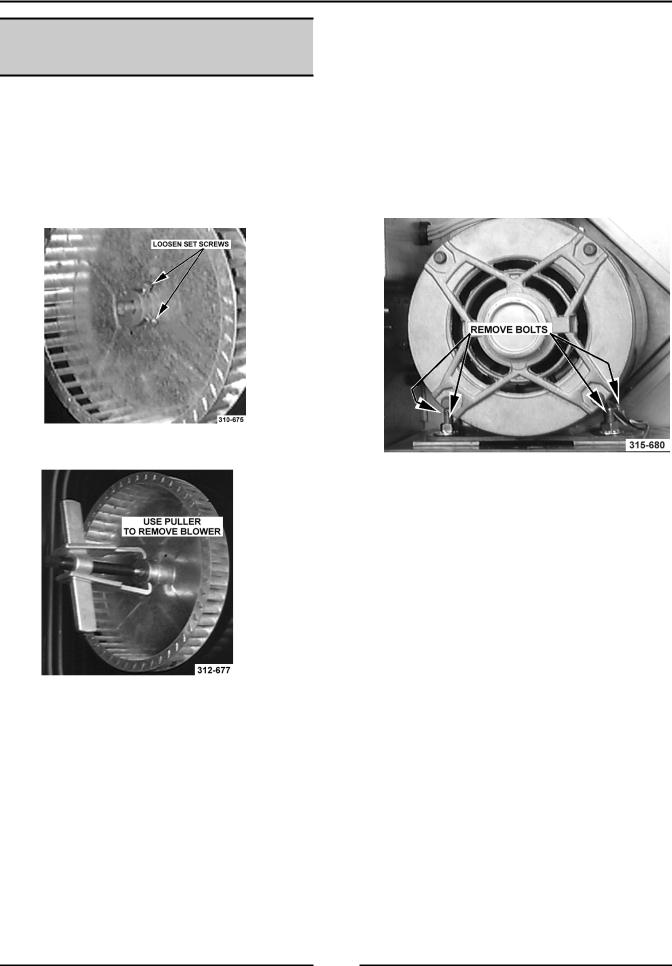
BLOWER AND/OR BLOWER
MOTOR
WARNING: UNPLUG UNIT BEFORE SERVICING.
1.Remove racks and the right rack support.
2.Remove baffle panel by lifting up and out.
3.For gas ovens only, remove the heat exchanger as outlined under “HEAT EXCHANGER”.
4.Loosen set screws on blower hub.
5.Remove blower from motor shaft. You may have to use a bearing puller.
6.If the blower only is to be replaced, reverse procedure to install and check blower to be parallel with the motor mounting plate as outlined under "BLOWER ADJUSTMENT" in "SERVICE PROCEDURES AND ADJUSTMENTS”. If the motor is to be replaced, continue to step 7.
8.Disconnect the wire leads to the motor.
A.P1 (purple) to wire# 11
B.Orange (Low speed) to wire# 12
C.Blue (high speed) to wire# 13
D.Red wires connected together.
9.Remove the bolts that secure the motor to the motor mounting plate and remove the motor from the oven.
10.Place new motor in position on the motor mounting plate and route the wiring through the grommet in the component panel.
11.Install mounting pads and bolts. DO NOT tighten mounting bolts.
12.Slide the blower onto motor shaft until hub is flush with end of shaft and tighten set screws.
13.Adjust motor position until blower is parallel to oven cavity wall with a spacing of ¼" as outlined under "BLOWER ADJUSTMENT" in "SERVICE PROCEDURES AND ADJUSTMENTS".
14.Install baffle panel, rack guides and racks.
7.Remove the right side panel.
6

HALF-SIZE CONVECTION OVENS - REMOVAL AND REPLACEMENT OF PARTS
OVEN DOOR
Removal
WARNING: UNPLUG UNIT BEFORE SERVICING.
1.Remove the top front cover as outlined under "COVERS AND PANELS".
Disassembly
1.Open the door.
2.Remove the door handle and latch plate.
3.Remove the screws which secure the inner and outer door panels to the door frame.
2.Remove the door switch lever from the door shaft.
3.Remove the door switch bracket.
4.While supporting the door, remove the bearing, door plate and spacer.
5.Lift the door from the lower bearing.
6.Reverse procedure to install door assembly and check for proper adjustment as outlined under "DOOR ADJUSTMENT" and "DOOR SWITCH ADJUSTMENT" in "SERVICE PROCEDURES AND ADJUSTMENTS".
4.Remove the inner and outer door panel.
5.Remove the four screws and lift the window assembly out.
NOTE: Use high temperature silicone between the window and the door panel.
6.Reverse the procedure to install the new window and adjust the door as outlined under “DOOR ADJUSTMENT”.
7
HALF-SIZE CONVECTION OVENS - REMOVAL AND REPLACEMENT OF PARTS
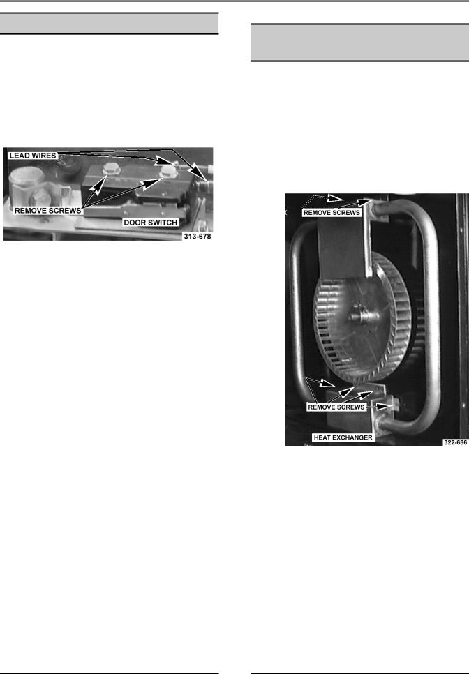
DOOR SWITCH
WARNING: UNPLUG UNIT BEFORE SERVICING.
1.Remove the top front cover as outlined under "COVERS AND PANELS".
2.Disconnect the leads to the door switch.
3.Remove the switch which is secured by two screws.
4.Reverse the procedure to install the new switch.
5.Adjust the door switch as outlined under "DOOR SWITCH ADJUSTMENT" in "SERVICE PROCEDURES AND ADJUSTMENTS".
HEAT EXCHANGER (GAS
OVENS)
WARNING: UNPLUG UNIT BEFORE SERVICING.
WARNING: SHUT OFF THE GAS BEFORE SERVICING THE UNIT.
1.Remove racks and the right rack support.
2.Remove baffle panel by lifting up and out.
3.Remove the screws that secure the heat exchanger and remove it from the oven.
4.Reverse procedure to install.
8
HALF-SIZE CONVECTION OVENS - REMOVAL AND REPLACEMENT OF PARTS
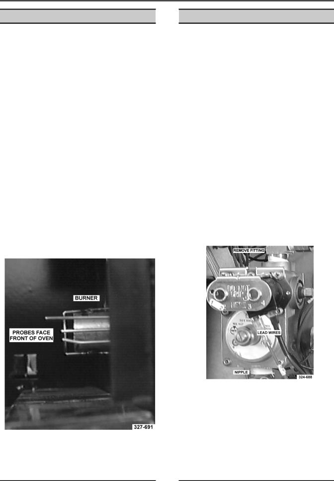
BURNER (GAS OVENS)
WARNING: UNPLUG UNIT BEFORE SERVICING.
WARNING: SHUT OFF THE GAS BEFORE SERVICING THE UNIT.
1.Remove racks and the right rack support.
2.Remove baffle panel by lifting up and out.
3.Remove the right side panel as outlined under “COVERS AND PANELS”.
4.Disconnect the lead wires to the electrode assembly.
5.Remove the heat exchanger as outlined under “HEAT EXCHANGER”.
6.Remove the screws from the burner bracket and pull the burner into the oven cavity.
7.Remove the screws that secure the electrodes to the burner bracket.
8.Reverse procedure to install.
NOTE: When installed, the electrodes are positioned toward the front of the oven.
GAS VALVE (GAS OVENS)
WARNING: UNPLUG UNIT BEFORE SERVICING.
WARNING: SHUT OFF THE GAS BEFORE SERVICING THE UNIT.
WARNING: ALL GAS JOINTS DISTURBED DURING SERVICING MUST BE CHECKED FOR LEAKS. CHECK WITH A SOAP AND WATER SOLUTION (BUBBLES). DO NOT USE AN OPEN FLAME.
A.CHECK ALL JOINTS PRIOR TO THE GAS VALVE BEFORE LIGHTING UNIT.
B.CHECK ALL JOINTS BEYOND GAS VALVE AFTER UNIT IS LIT.
1.Remove the right side panel and control panel as outlined under “COVERS AND PANELS”.
2.Disconnect the lead wires at the gas valve.
3.Disconnect the gas line fitting going to the burner at the top of the gas valve.
4.Remove the gas valve from the nipple between the it and the manual gas valve.
5.Reverse procedure to install.
6.Adjust the gas valve as outlined under “GAS PRESSURE ADJUSTMENT”.
9

HALF-SIZE CONVECTION OVENS - REMOVAL AND REPLACEMENT OF PARTS
HEATING ELEMENTS (ELECTRIC OVENS)
WARNING: DISCONNECT THE ELECTRICAL POWER TO THE MACHINE AT THE MAIN CIRCUIT BOX. PLACE A TAG ON THE CIRCUIT BOX INDICATING THE CIRCUIT IS BEING SERVICED.
1.Remove racks and the right rack support.
2.Remove baffle panel by lifting up and out.
3.Remove the right side panel as outlined under “COVERS AND PANELS”.
4.Disconnect the lead wires to the heating elements.
5.Remove the screws from the clamps that secure the heating element assembly.
6.Pull the top of the heating element assembly into the oven cavity until the ends of the elements are inside the oven cavity. Lift up and remove the lower clamp from between the side wall and the bottom of the oven cavity.
7.Remove the clamps from the heating element assembly and replace the element(s).
8.Reverse procedure to install.
TEMPERATURE PROBE
Procedure
WARNING: UNPLUG UNIT BEFORE SERVICING.
1.Remove the control panel as outlined under "COVERS AND PANELS".
2.Disconnect the probe leads at the temperature control.
3.Remove probe from the probe guard and push it thru the oven wall into the control panel area.
NOTE: When installing, only the metal surface of the probe should be inserted into the probe guard.
NOTE: The probe may have to be inserted at an angle. The hole in the inside oven cavity wall may not line up straight with the oven cavity outer shell.
4.Reverse the procedure to install the new probe.
5.Adjust the temperature control as outlined under "TEMPERATURE CONTROL CALIBRATION" in "SERVICE PROCEDURES AND ADJUSTMENTS".
10
HALF-SIZE GAS CONVECTION OVENS - SERVICE PROCEDURES AND ADJUSTMENTS
SERVICE PROCEDURES AND ADJUSTMENTS
WARNING: CERTAIN PROCEDURES IN THIS SECTION REQUIRE ELECTRICAL TEST OR MEASUREMENTS WHILE POWER IS APPLIED TO THE MACHINE. EXERCISE EXTREME CAUTION AT ALL TIMES. IF TEST POINTS ARE NOT EASILY ACCESSIBLE, DISCONNECT POWER, ATTACH TEST EQUIPMENT AND REAPPLY POWER TO TEST.
TEMPERATURE PROBE TEST (ALL MODELS)
WARNING: UNPLUG UNIT BEFORE SERVICING.
1.Remove the right side panel as outlined under "COVERS AND PANELS".
2.Remove the probe lead wires from the electronic control.
3.Test the probe with an ohmmeter.
|
|
|
|
|
TEMPERA- |
|
RESISTANCE |
|
TURE |
|
in ±10% |
|
in F |
|
|
|
77 |
|
90000 |
|
240 |
|
4077 |
|
260 |
|
3016 |
|
280 |
|
2266 |
|
300 |
|
1726 |
|
320 |
|
1332 |
|
340 |
|
1041 |
|
360 |
|
822 |
|
380 |
|
656 |
|
400 |
|
529 |
|
425 |
|
424 |
|
450 |
|
334 |
|
475 |
|
266 |
|
|
|
|
VERIFICATION OF SPARK
AT SPARK PROBE
WARNING: UNPLUG UNIT BEFORE SERVICING.
WARNING: SHUT OFF THE GAS BEFORE SERVICING THE UNIT.
1.Remove the right side panel and control panel as outlined under “COVERS AND PANELS”.
2.Disconnect the high voltage lead from the electrode.
WARNING: DO NOT HOLD THE WIRE WITH YOUR HANDS FOR THIS TEST. THE MANUAL GAS VALVE MUST BE CLOSED.
3.Clamp the wire in such a manner that the end of the wire is 3/16" from the frame of the oven.
NOTE: It is critical that the wire be held 3/16" away from the oven or sparking may not occur even though the probe circuits are functioning properly.
WARNING: THE FOLLOWING STEPS REQUIRE POWER TO BE APPLIED TO THE UNIT DURING THE TEST. USE EXTREME CAUTION AT ALL TIMES.
4.Plug the unit in and set the temperature controller to the maximum setting.
5.Turn the power switch on.
6.Sparking should occur after a 15 second purge time. Arcing from the lead wire to the oven frame should be observed at this time.
11
HALF-SIZE GAS CONVECTION OVENS - SERVICE PROCEDURES AND ADJUSTMENTS
GAS PRESSURE |
|
GAS TYPE |
SETTING AT OUTPUT |
ADJUSTMENT |
|
|
OF GAS VALVE |
|
|
|
|
|
Natural |
3.5 inches W.C. |
|
WARNING: UNPLUG UNIT BEFORE SERVICING. |
|
||
|
|
|
|
|
Propane |
10 inches W.C. |
|
|
|
||
|
|
|
|
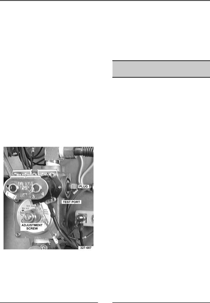
WARNING: SHUT OFF THE GAS BEFORE SERVICING THE UNIT.
1.Remove the right side panel and control panel as outlined under “COVERS AND PANELS”.
2.Remove the plug from the test port and install the manometer.
WARNING: THE FOLLOWING STEPS REQUIRE POWER TO BE APPLIED TO THE UNIT DURING THE TEST. USE EXTREME CAUTION AT ALL TIMES.
3.Plug in the unit and turn on the gas.
4.Set the temperature control to the highest setting and turn the power switch on. The burner must be lit while adjusting the pressure.
5.Turn the adjustment screw to obtain the proper gas pressure.
•Turn screw clockwise to increase pressure.
•Turn screw counterclockwise to decrease pressure.
NOTE: If input pressure is below 4.0 (Natural) or 10.5 (Propane) inches W.C., the desired output cannot be obtained and the oven will overate at a lower BTU.
SPARK IGNITION CONTROL
TEST
WARNING: UNPLUG UNIT BEFORE SERVICING.
NOTE: Verify that the ground terminal is connected to the oven ground.
No Gas Ignition & No Sparking
1.Remove the right side panel as outlined under “COVERS AND PANELS”.
2.Plug in the unit and set the temperature controller to 350°.
3.Turn the power switch on.
4.Check for 24 VAC between the power terminal and ground terminal.
A.If 24 VAC is present, replace the spark ignition control.
B.If 24 VAC is not present, check the transformer, temperature controller, and switches.
No gas ignition - sparking occurs
1.Remove the right side panel as outlined under “COVERS AND PANELS”.
2.Plug in the unit and set the temperature controller to 350°.
3.Turn the power switch on.
4.Check for 24 VAC between the gas valve terminal and the ground terminal. The voltage should be present after the 15 second purge and during the 10 second ignition period.
A.If 24 VAC is present, check the gas valve and gas supply.
B.If 24 VAC is not present, replace the spark ignition control.
12
 Loading...