


2GR45AF
Vulcan-Hart 2GR45AF, 2GR65AF, 1GR85A, 1GR85AF, 2GR85AF User Manual
...
INSTALLATION & OPERATIONAL MANUAL
1GRA & GRAF SERIES GAS FRYERS
VFRY18 & VFRY18F HDR FRYERS
With KleenScreen PLUS® Filtration Systems
MODELS:
1GR45A ML-136647
1GR65A ML-136648
1GR85A ML-136649
1GR45AF ML-136798
1GR65AF ML-136795
1GR85AF ML-136796
2GR45AF ML-136650
3GR45AF ML-136653
4GR45AF ML-136656
2GR65AF ML-136651
3GR65AF ML-136654
2GR85AF ML-136652
3GR85AF ML-136655
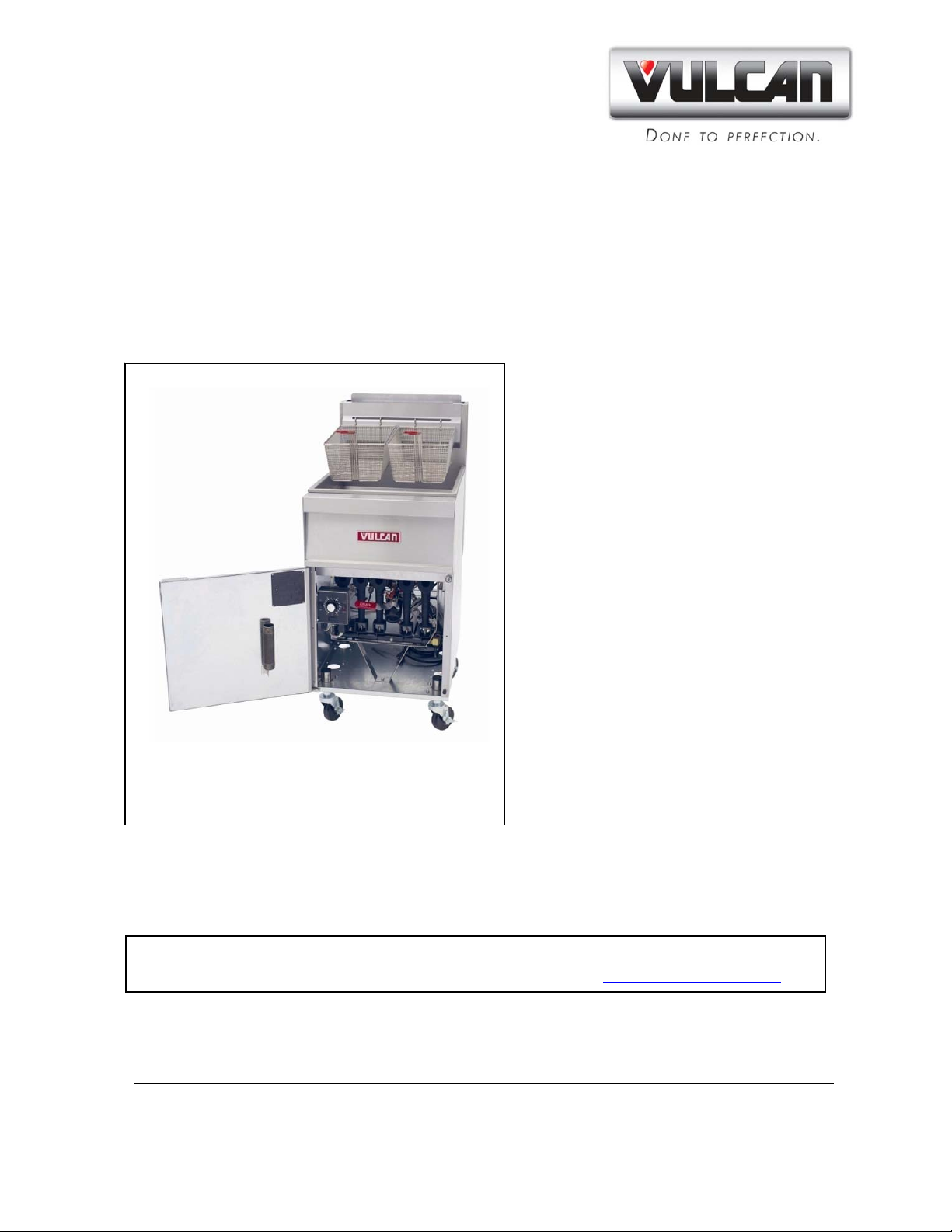
1GR45A Shown -
Solid State Control
VFRY18
Secured Behind the Door VFRY18F
VFRY18
For additional information on Vulcan-Hart or to locate an authorized parts
and service provider in your area, visit our website at www.VulcanHart.com
VULCAN-HART 3600 NORTH POINT BLVD.
DIVISION OF ITW FOOD EQUIPMENT GROUP, LLC BALTIMORE, MD 21222
www.VulcanHart.com F-32934 REV. J (August 2012)
GRA, GRAF, & VFRY GAS FRYERS & VFRY SERIES HD FRYERS
VULCAN-HART F-32934 Rev. J (August 2012)
-2-
IMPORTANT FOR YOUR SAFETY
THIS MANUAL HAS BEEN PREPARED FOR PERSONNEL QUALIFIED TO INSTALL
GAS EQUIPMENT, WHO SHOULD PERFORM THE INITIAL FIELD START-UP AND
ADJUSTMENTS OF THE EQUIPMENT COVERED BY THIS MANUAL.
POST IN A PROMINENT LOCATION THE INSTRUCTIONS TO BE FOLLOWED IN THE
EVENT THE SMELL OF GAS IS DETECTED. THIS INFORMATION CAN BE
OBTAINED FROM THE LOCAL GAS SUPPLIER.
IMPORTANT
IN THE EVENT A GAS ODOR IS DETECTED, SHUT DOWN UNITS AT THE MAIN
SHUTOFF VALVE AND CONTACT THE LOCAL GAS COMPANY OR GAS SUPPLIER
FOR SERVICE.
FOR YOUR SAFETY
DO NOT STORE OR USE GASOLINE OR OTHER FLAMMABLE
VAPORS OR LIQUIDS IN THE VICINITY OF THIS OR ANY
OTHER APPLIANCE.
Improper installation, adjustment, alteration, service or
maintenance can cause property damage, injury or death.
Read the installation, operating and maintenance instructions
thoroughly before installing or servicing this equipment.

GRA, GRAF, & VFRY GAS FRYERS & VFRY SERIES HD FRYERS
VULCAN-HART F-32934 Rev. J (August 2012)
-3-
TABLE OF CONTENTS
IMPORTANT FOR YOUR SAFETY………………………………………. 2
INTRODUCTION…………………………………………………………… 4
GENERAL…………………………………………………………… 4
ORDERING PARTS………………………………………………… 4
FRYER CAPACITIES………………………………………………. 4
UNPACKING………………………………………………………… 4
INSTALLATION………………………………………………………...…… 5
Clearances…………………………………………………... 6
Location ………………..……………………………….…. 6
CODES AND STANDARDS……………………………………….. 6
ASSEMBLY …………..…………………………………………… 7
FLUE CONNECTION………………………………………………. 7
GAS CONNECTION…………………………………………………. 7
GAS PRESSURES........................................................................ 8
TESTING GAS SUPPLY PIPING SYSTEM……………………… 8
Fryers with Casters…………………………………….… 8
ELECTRICAL CONNECTION…………………………………… 9
LEVELING THE FRYER………………………………………..…… 10
OPERATION………………………………………………………………… 10
OVER-TEMPERATURE SHUTDOWN……………………………. 10
BEFORE FIRST USE………………………………………………... 10
Cleaning………………………………………………….... 10
FILLING TANK WITH SHORTENING…………………………… 11
BASIC FRYING INSTRUCTIONS……………………………….. 11
Fry Basket Guidelines……………………………………. 12
EXTENDING SHORTENING LIFE………………………………… 12
TURNING ON THE FRYER ……………………………………… 13
TURNING OFF THE FRYER ……………………………………. 13
SOLID STATE KNOB CONTROLS GUIDE………………………. 14
START UP IN 4 EASY STEPS …………………………………… 14
EXTENDED SHUTDOWN …………………………………….. 15
FILTERING THE OIL………………………………………………. 15
DRAINING THE TANK……………………………….…………….. 16
BOIL OUT PROCEDURE…………………………………………..……..... 16
CLEANING…………………………………………………………... 17
Daily…………………………………………………………. 17
KLEENSCREEN PLUS® INSTALLATION & OPERATION…………… 18
GAS MODELS…………………………………………………..…… 18
FILTERING INSTRUCTONS FOR KLEENSCREEN PLUS® …………... 19
GENERAL………………………………………………….…………. 19
ASSEMBLY………………………………………………………….. 19
INSTRUCTIONS TO REMOVE & REPLACE FILTER ENVELOPE…….. 21
OPERATION ……………………………………………………………….. 22
FILTERING PROCEDURE ………………………………………… 22
SOLID STATE KNOB CONTROLS ……………………..………. 23
FILTERING IN 7 EASY STEPS……………………………………. 23
FILTERING TIPS …………………………………………………… 24
REMOVING EXCESS DEBRIS FROM THE FILTER ………….. 24
FLUSH AND DISCARD …………………………………………….. 24
BOIL OUT PROCEDURE …………………………………………. 25
THERMAL OVERLOAD PROTECTION RESET BUTTON …….. 25
MAINTENANCE……………………………………………………………… 26
FLUE VENT INSPECTION……………………………………….. 26
Service in the US and Canada…………………………………... 26
In Australia…………………………………………………………. 26
TROUBLESHOOTING……………………………………………………… 26
GRA, GRAF, & VFRY GAS FRYERS & VFRY SERIES HD FRYERS
VULCAN-HART F-32934 Rev. J (August 2012)
-4-
INTRODUCTION
GENERAL
Vulcan Fryers are produced with quality workmanship and material. Proper installation,
usage and maintenance will result in years of satisfactory performance.
Before installing the fryer, thoroughly read this manual and carefully follow all instruction.
This manual is applicable to model listed on the cover page. Procedures in this manual
will apply to all models unless specified. Pictures and illustrations can be of any model
unless the picture or illustration needs to be model specific.
ORDERING PARTS
Customers may order parts directly from their local authorized service center. If not
known, call Vulcan Customer Service at 800-814-2028.
To speed up your order, provide the model number, serial number, gas type, part needed,
item part number (if known) and quantity needed.
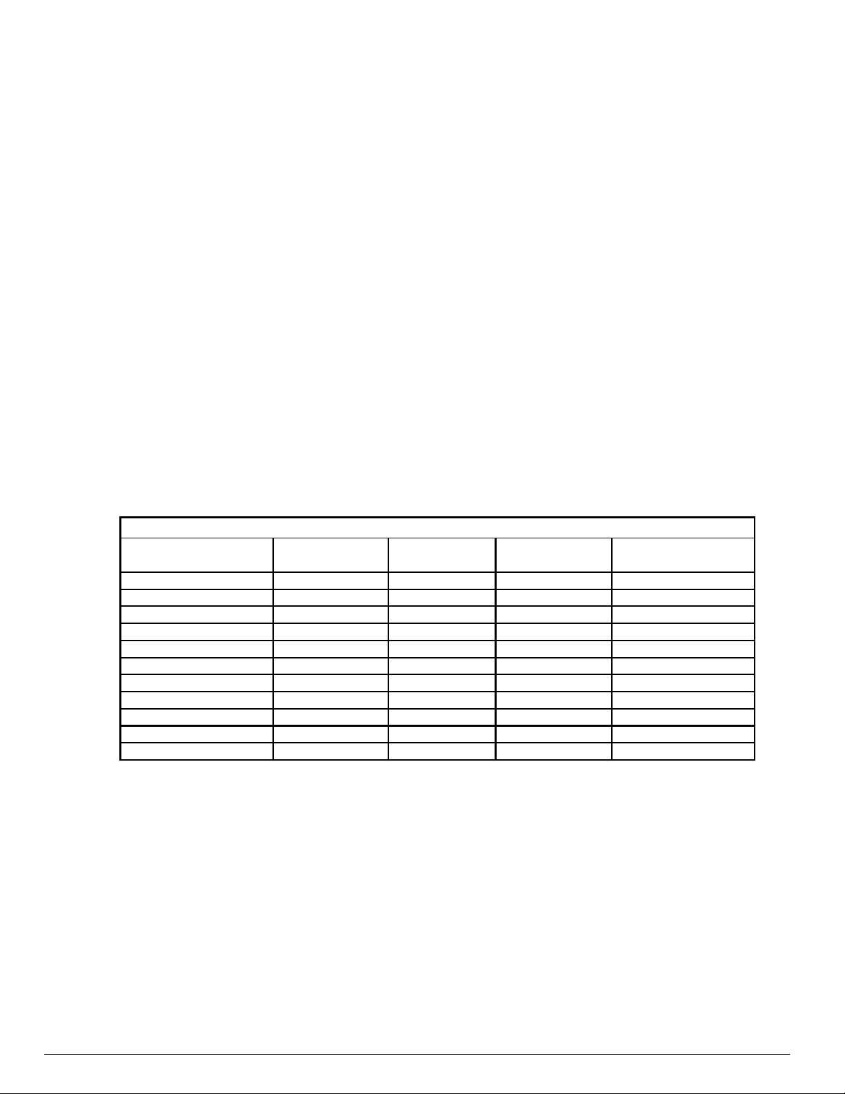
MODEL - GMO
# of Heat Tubes
Each Fr
y
Tank
BTU / Hour
Each Fr
y
Tank
Width Inch (cm)
Total S
y
stem
Shortening lbs. (kg)
Each Fr
y
Tank
1GR45A /AF 4 120,000 15.5" (39) 45-50 (21-23)
1GR65A /AF 5 150,000 21.0" (53) 65-70 (29-32)
1G585A /AF 5 150,000 21.0" (53) 85-90 (39-41)
2GR45AF 4 120,000 31.0" (79) 45-50 (21-23)
3GR45AF 4 120,000 46.5" (118) 45-50 (21-23)
4GR45AF 4 120,000 62.0" (158) 45-50 (21-23)
2GR65AF 5 150,000 42.0" (107) 65-70 (29-32)
3GR65AF 5 150,000 63.0" (160) 65-70 (29-32)
2GR85AF 5 150,000 42.0" (107) 85-90 (39-41)
3GR85AF 5 150,000 63.0" (160) 85-90 (39-41)
VFRY18 /F 4 120,000 15.5" (39) 45-50 (21-23)
FRYER CAPACITY
UNPACKING
This fryer was carefully inspected before leaving the factory. Upon acceptance of the
shipment, the transportation company assumes full responsibility for safe delivery.
Immediately after unpacking the fryer, check for possible shipping damage. If the fryer is
damaged, save the packaging material and contact the carrier within 15 days of delivery.

GRA, GRAF, & VFRY GAS FRYERS & VFRY SERIES HD FRYERS
VULCAN-HART F-32934 Rev. J (August 2012)
-5-
Check that the following have been included:
Crumb Rack(s)
Basket Hanger(s)
Tank Brush
Adjustable Casters (4) two locking, two non-locking for freestanding fryers. Fryer
Batteries with the KleenScreen PLUS® Filtration System have casters installed from
the factory.
Drain Pipe Extension for freestanding fryers only.
Twin Fry Baskets (2) per fry tank
Cleanout Rod for freestanding fryers only.
Crumb Scoop for freestanding fryers only.
Fryer Batteries with the KleenScreen PLUS® Filtration System
Filter Pan
Suction Tube
Screen Assembly
Complimentary Pack of Micro-Filtration Envelopes
6’ (1829 mm) long high temperature discard hose
Manual, Quick Start Guide(s), and Warranty – Retain for future reference
INSTALLATION
Do not use the door or its handle to lift the fryer.
Before installing the fryer, verify that the type of gas (natural or propane) agrees with the
specifications on the fryer data plate, which is located on the inside of the door panel.
Make sure the fryer is configured for the proper elevation.
Record your fryer model, device, and serial numbers for future reference in the space
provided below. This information can be found on the fryer data plate.
Fryer Model No: ___________________________
Device: ___________________________________
Serial No: ________________________________

GRA, GRAF, & VFRY GAS FRYERS & VFRY SERIES HD FRYERS
VULCAN-HART F-32934 Rev. J (August 2012)
-6-
Clearances:
Minimum clearance from combustible construction:
6” (15 cm) from the sides of the fryer
6” (15 cm) from the back of the fryer
The fryer may be installed on combustible floors.
Minimum clearance from noncombustible construction:
0” from the sides of the fryer
0” from the back of the fryer
Between the fryer and any open-top flame units:
16” (41 cm)
Allow space for servicing and operation.
Location:
Install fryer in an area with sufficient air supply for gas combustion at fryer burners.
Do not obstruct the flow of combustion and ventilation air.
Provide adequate clearance for air openings into the combustion chamber.
Do not permit fans to blow directly onto fryer.
Avoid wall-type fans, which create cross-currents within a room. Avoid open
windows next to sides or back.
CODES AND STANDARDS
The fryer must be installed in accordance with:
In the United States:
State and local codes, or in the absence of local codes, with:
National Fuel Gas Code, ANSI-Z223.1/NFPA #54 (latest edition). Copies may be
obtained from The American Gas Association Accredited Standards Committee
Z223, @ 400 N. Capital St. NW, Washington, DC 20001 or the Secretary Standards
Council, NFPA, 1 Batterymarch Park Quincy, MA 02169-7471.
NFPA Standard #96 Vapor Removal from Cooking Equipment, latest edition,
available from the National Fire Protection Association, Batterymarch Park,
Quincy, MA. 02169-7471.

GRA, GRAF, & VFRY GAS FRYERS & VFRY SERIES HD FRYERS
VULCAN-HART F-32934 Rev. J (August 2012)
-7-
National Electrical Code, ANSI/NFPA-70 (latest edition). Copies may be obtained
from The National Fire Protection Association, Batterymarch Park, Quincy, MA.
02169-7471.
In the commonwealth of Massachusetts all gas appliances vented through a
ventilation hood or exhaust system with a damper or with a power means of
exhaust shall comply with 248 CMR.
In Canada:
Local codes
CAN/CSA-B149.1 Natural Gas and Propane Installation Code (latest
edition), available from the Canadian Standards Association, 155 Queen Street,
Suite 1300, Ottawa, Ontario Canada K1P 6L1.
CSA C22.1 Canadian Electric Code (latest edition), available from the Canadian
Standards Association, 155 Queen Street, Suite 1300, Ottawa, Ontario Canada
K1P 6L1.
ASSEMBLY
The fryer must be restrained to prevent tipping and the splashing of hot liquid. The means
of restraint may be the manner of installation, such as connection to a battery of
appliances, installing the fryer in an alcove, or by separate means such as adequate ties.
FLUE CONNECTION
Make the flue connection as follows:
Comply with Vapor Removal from Cooking Equipment, ANSI-NFPA Standard
#96 (latest edition), available from the National Fire Protection Association,
Batterymarch Park, Quincy, MA 02269.
Locate the fryer under a hood with adequate connection to an exhaust duct.
The hood must extend 6” (15 cm) beyond fryer on both sides.
Clearance above the fryer should be adequate for combustion byproducts to be
removed efficiently.
An 18” (46 cm) minimum clearance should be maintained between the flue vent
and the filters of the hood venting system.
Never make flue connections directly to the fryer.
Do not obstruct the flow of the gases from the appliance. Proper air balance
should be maintained in the room.
Ensure that your ventilation system does not cause a down draft at the fryer’s flue
opening. Down draft will not allow the fryer to exhaust properly and will cause
overheating which may cause permanent damage. Damage caused by down draft
will not be covered under equipment warranty. Never allow anything to obstruct the
flue or ventilation exiting from the fryer flue. Do not put anything on top of flue area.
GRA, GRAF, & VFRY GAS FRYERS & VFRY SERIES HD FRYERS
VULCAN-HART F-32934 Rev. J (August 2012)
-8-
GAS CONNECTION
All gas supply connections and any pipe joint compound must be
resistant to the action of propane gases.
The gas inlet is located on the lower rear of the fryer. Codes require that a gas shutoff
valve be installed in the gas line ahead of the fryer.
The gas supply line must be at least the equivalent of ½” (12.7 mm) iron pipe for single
units and 1-1/4” (31.75 mm) for batteries. If using the optional quick-disconnect flex hose,
¾” (19 mm) iron pipe for single units and 1-1/4” (31.75 mm) iron pipe for batteries.
Make sure the pipes are clean and free of obstructions, dirt, and piping compound. A
battery requires one or two connections of appropriate size for the gas requirement.
Prior to lighting, check all joints in the gas supply line for leaks.
Use soap and water solution. Do not use an open flame.
After piping has been checked for leaks, fully purge gas pipes to remove air.
GAS PRESSURES (ALL MODELS):
The gas pressure should be set at 4” W.C. (Water Column) (0.8 kPa) for natural gas and
10” W.C. (2.75 kPa) for propane gas. If incoming pressure exceeds ½ PSI (3.45 kPa), an
additional pressure regulator must be installed.
TESTING THE GAS SUPPLY PIPING SYSTEM:
When test pressures exceed ½ PSI (3.45 kPa), the fryer and its individual shutoff valve
must be disconnected from the gas supply piping system.
When test pressures are ½ PSI (3.45 kPa) or less, the fryer must be isolated from the gas
supply piping system by closing its individual shutoff valve.
Fryers with Casters:
Separate instructions for installing casters are included with the casters:
The installation shall be made with a connector that complies with the
Standard for Connectors for Movable Gas Appliances, ANSI Z21.69 or Connectors
for Moveable Gas Appliances, CAN/CGA-6.16, and a quick-disconnect device that
complies with the Standard for Quick-Disconnect Devices for Use with Gas Fuel,
ANSI z21.41 or Quick-Disconnect Devices for Use with Gas Fuel, CANI-6.9.
 Loading...