


ES30
Vulcan Hart ES30, EL40, ES60, EL80, ET125 Operation Manual
...
INSTALLATION , OPERATION
SERVICE & PARTS MANUAL
ES, EL & ET STEAM JACKETED KETTLES
MODELS
ES25 ML-52642
ES30 ML-52643
EL40 ML-52644
ES60 ML-52645
EL80 ML-52646
ET100 ML-52647
ET125 ML-52648
ET150 ML-52649
For additional information on Vulcan-Hart Company or to locate an authorized
parts and service provider in your area, visit our Web site at www.vulcanhart.com
VULCAN-HART COMPANY, P.O. BOX 696, LOUISVILLE, KY 40201-0696, TEL. (502) 778-2791
FORM 30965 Rev. A (06-03)

TABLE OF CONTENTS
GENERAL.............................................................................................................................................................. 3
INSTALLATION .....................................................................................................................................................3
Unpacking .................................................................................................................................................3
Location ....................................................................................................................................................3
Leveling .................................................................................................................................................... 3
Installation Codes and Standards ...........................................................................................................3
Electrical Connections .............................................................................................................................4
Faucet Connection (Optional) ................................................................................................................. 4
OPERATION .........................................................................................................................................................5
Before First Use .......................................................................................................................................5
Controls .................................................................................................................................................... 5
Filling the Water Jacket ...........................................................................................................................6
Using the Kettle ........................................................................................................................................6
Kettle Food Draw-Off Valve .....................................................................................................................6
Cleaning.................................................................................................................................................... 6
MAINTENANCE ....................................................................................................................................................8
Periodic Maintenance .............................................................................................................................. 8
Pressure Relief Valve ............................................................................................................... 8
Low Water Cut-Off ....................................................................................................................8
Sight Glass Assembly............................................................................................................... 8
Draw-Off Valve .......................................................................................................................... 8
Vent ........................................................................................................................................... 8
Kettle Jacket Fluid ....................................................................................................................8
SERVICE ............................................................................................................................................................... 9
General Notes ..........................................................................................................................................9
Servicing Procedures ............................................................................................................................... 9
Thermostat ................................................................................................................................9
Low Water Cut-Off ..................................................................................................................10
Pressure Limit Switch .............................................................................................................10
Magnetic Contactor ................................................................................................................. 10
Electric Heating Elements ......................................................................................................10
Replace On-Off Switch ........................................................................................................... 11
Replace Signal Light ............................................................................................................... 11
Replace Pressure Gauge .......................................................................................................11
Correct Leaking Draw-Off Valve ............................................................................................11
Service and Parts Information ............................................................................................................... 11
PARTS LIST ........................................................................................................................................................ 12
WIRING DIAGRAMS...........................................................................................................................................14
DIMENSIONS AND SERVICE CONNECTIONS ...............................................................................................18
© VULCAN-HART COMPANY, 2003
– 2 –

Installation, Operation and Care of
MODEL ES, EL & ET STEAM JACKETED KETTLES
KEEP THESE INSTRUCTIONS FOR FUTURE REFERENCE
GENERAL
Your Vulcan steam jacketed kettle is produced with quality workmanship and material. Proper
installation, usage and maintenance will result in many years of satisfactory performance.
Vulcan-Hart Company suggests that you thoroughly read this entire manual and carefully follow all of
the instructions provided.
INSTALLATION
Prior to installation verify that the electrical service agrees with the specifications on the machine data
plate located inside the front cover at the lower left.
UNPACKING
This kettle was inspected before leaving the factory. The transportation company assumes full
responsibility for safe delivery upon acceptance of the shipment. Immediately after unpacking, check
for possible shipping damage. If the kettle is found to be damaged, save the packaging material and
contact the carrier within 15 days of delivery.
LOCATION
Position the kettle in its final location. Check that there are sufficient clearances for operating and
servicing the kettle, and for proper clearance of the cover when raised. The kettle draw off faucet should
be located near a floor drain.
LEVELING
Place a spirit level on the rim of the kettle with the cover open. Adjust the feet to level the kettle leftto-right and front-to-back.
INSTALLATION CODES AND STANDARDS
Vulcan kettles must be installed in accordance with:
In the United States:
1. Local codes.
2. National Electrical Code ANSI/NFPA-70 (latest edition).
– 3 –
3. ANSI NFPA Standard #96 "Vapor Removal from Cooking Equipment," (latest edition), available
from the National Fire Protection Association, Batterymarch Park, Quincy, MA 02269.
In Canada:
1. Local codes.
2. CSA Standard C22.1 Canadian Electrical Code, Part 1.
ELECTRICAL CONNECTIONS
WARNING: ELECTRICAL AND GROUNDING CONNECTIONS MUST COMPLY WITH THE
APPLICABLE PORTIONS OF THE NATIONAL ELECTRICAL CODE AND/OR OTHER LOCAL
ELECTRICAL CODES.
WARNING: DISCONNECT ELECTRICAL POWER SUPPLY AND PLACE A TAG AT THE
DISCONNECT SWITCH TO INDICATE THAT YOU ARE WORKING ON THE CIRCUIT.
Make required electrical supply connections at the junction box located below the control box. There
is no opening in the junction box for supply line conduit. The box is a sealed box and the conduit
connection should be made with fittings of the water resistant type. Be sure the supply wiring and the
circuit protection are adequate for the K.W. load drawn by the kettle. The wiring diagram is located on
the back side of the removable control cover. Use copper wire suitable for at least 75°C temperature.
If the kettle is for operation on an electric supply of over 240 volts, a transformer is provided to reduce
the control circuit voltage to 120 volts.
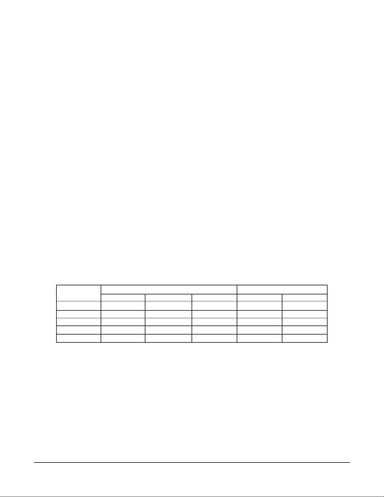
ELECTRICAL DATA CHART
NOMINAL AMPS PER LINE WIRE
3 PHASE 1 PHASE
K.W. 208 230-240 440-460-480 208 230-240
12 33.4 28.9 14.5 57.6 50.0
18 50.0 43.4 21.7 86.5 75.0
24 66.7 57.8 28.9 115.4 100.0
36 100.0 86.8 43.4 — —
43.2 119.9 104.0 52 — —
Each of the two elements draws one-half of the above listed total amperage.
FAUCET CONNECTION (Optional)
If the optional faucet assembly is to be installed, connect as required.
– 4 –

OPERATION
WARNING: THE KETTLE AND ITS PARTS ARE HOT. USE CARE WHEN OPERATING, CLEANING
AND SERVICING THE KETTLE.
BEFORE FIRST USE
Using a non-corrosive, grease-dissolving commercial cleaner, clean the protective metal oils from all
surface parts and interior of the kettle. Follow the cleaner manufacturer's directions. Rinse thoroughly
with warm water to remove all traces of the cleaner. Drain the kettle. Wipe dry with a soft clean cloth.
CONTROLS
On-Off Switch — Turns power to the kettle on or off.
Thermostat Switch, — These three switches are wired in series and control the supply of
Low Water Cutoff Switch, energy to the heating elements. Opening any one of these pressure
Limit Switch switches will shut off the power supply to the heating elements.
Thermostat — Senses the temperature in the steam jacket. At a dial setting of 5 to
6, it will cut power off as the pressure gauge needle moves off zero.
The higher dial settings
holding. At the higher dial settings,
jacket will drop to 2 to 2
off and before it cuts it on.
are for cooking, the lower ones for
1
/2 psi after the thermostat cuts the power
the steam pressure in the
Low Water Cutoff Switch — Cuts off power to the heating elements if the jacket distilled water
level is too low.
Pressure Relief Valve, — Protect the kettle against excessive pressure should the thermostat
Pressure Limit Switch
Pressure Gauge — Indicates pressure in the jacket.
Sight Glass Assembly — Visually shows the distilled water depth in the steam jacket.
Thermostatic Air Vent —
Fill Assembly — Location for adding distilled water to the jacket. It is equipped with
Food Draw-Off Valve — Allows food and liquid to be drawn off from the kettle.
malfunction. The pressure relief valve is rated so that it will
relieve
generate it.
Lets air out of jacket as steam is generated; closes at
approximately 180°F to prevent the steam from escaping.
a manual valve plus a check valve to prevent a discharge should the
manual valve be inadvertently opened while the jacket is under
pressure.
generated steam faster than the heating elements can
– 5 –

FILLING THE WATER JACKET
APPLIANCE FAILURE CAUSED BY INADEQUATE WATER QUALITY IS NOT COVERED UNDER
WARRANTY.
Fill the outer jacket of the kettle to the top of the band on the gauge glass with a chemically pure distilled
water, along with a suitable rust inhibitor.
It should not be necessary to frequently add distilled water to the jacket, as little distilled water is lost
in normal operation.
USING THE KETTLE
Before use, preheat the kettle empty. Set the thermostat at No. 12 or No. 13. When the orange light
goes out, load food and set thermostat dial for desired cooking temperature.
KETTLE FOOD DRAW-OFF VALVE
When the food draw-off valve is turned off (no liquid or food product flow), the valve handle will point
to either the 9 o'clock or 3 o'clock position. To open (allowing liquid or food product flow), slowly pull
handle forward. With the valve handle pointing to the 6 o'clock position, the valve is in a fully open
position. This food draw-off valve system requires a right or left turn to close off food flow.
To allow for evenly mixed food products to flow into a food service pan or stock pot, first thoroughly stir
the food product in the kettle before opening the food draw-off valve. Pans or pots may be placed on
a portable dolly for easy movement and handling.
CLEANING
WARNING: DISCONNECT ELECTRICAL POWER SUPPLY BEFORE CLEANING.
After Each Use
Clean and flush the kettle immediately after each use, especially if the product cooked contained salt
or vinegar in any concentration.
Daily — Kettle Food Draw-Off Valve
1. With kettle empty, pull valve handle to the 7 o'clock position. (A pin locks the valve plug into the
valve body and you can only remove or replace the valve plug when the valve handle is in the
7 o'clock position.) Kettles built before July 2003 thru March 1992 - the removable position is at 4
o'clock. Kettles built prior to March 1992 - the removable position is at 6 o'clock.
2. Pull tapered plug from valve body.
3. Using warm soapy water, wash the entire valve body and open area into the kettle interior.
4. Wash the interior and exterior of the valve plug. CAUTION: Do not drop or hit the valve plug.
This will nick or dent the soft metal.
– 6 –
 Loading...