


SERVICE MANUAL
GAS RESTAURANT RANGE
EG24, 36, 48, 60, 160 AND 260
MODEL
EG24 ML-52486
EG36 ML-52487
EG48 ML-114956
EG60 ML-52488
EG160 ML-52489
EG260 ML-52490
EG36
VULCAN - HART COMPANY, P . O . BOX 696, LOUISVILLE, KY 40201 - 0696, TEL. (502) 778 - 2791
FORM 31054 Rev. A (5-98)
IMPORTANT FOR YOUR SAFETY
THIS MANUAL HAS BEEN PREPARED FOR PERSONNEL QUALIFIED TO INSTALL GAS EQUIPMENT, WHO SHOULD PERFORM THE INITIAL FIELD START-UP AND ADJUSTMENTS OF THE EQUIPMENT COVERED BY THIS MANUAL.
POST IN A PROMINENT LOCATION THE INSTRUCTIONS TO BE FOLLOWED IN THE EVENT THE SMELL OF GAS IS DETECTED. THIS INFORMATION CAN BE OBTAINED FROM THE LOCAL GAS SUPPLIER.
IMPORTANT
IN THE EVENT A GAS ODOR IS DETECTED,
SHUT DOWN UNITS AT MAIN SHUT-OFF VALVE
AND CONTACT THE LOCAL GAS COMPANY OR
GAS SUPPLIER FOR SERVICE.
FOR YOUR SAFETY
DO NOT STORE OR USE GASOLINE OR OTHER
FLAMMABLE VAPORS OR LIQUIDS IN THE
VICINITY OF THIS OR ANY OTHER APPLIANCE.
WARNING
IMPROPER INSTALLATION, ADJUSTMENT,
ALTERATION, SERVICE OR MAINTENANCE CAN
CAUSE PROPERTY DAMAGE, INJURY OR
DEATH. READ THE INSTALLATION,
OPERATING AND MAINTENANCE
INSTRUCTIONS THOROUGHLY BEFORE
INSTALLING OR SERVICING THIS EQUIPMENT.
IN THE EVENT OF A POWER FAILURE, THE PILOTS WILL REMAIN LIT AND THE UNIT WILL CONTINUE TO FUNCTION. UNITS EQUIPPED FOR 120 VOLT OPERATION WILL AUTOMATICALLY SHUT DOWN. SHOULD THIS HAPPEN, TURN POWER SWITCH OFF. DO NOT ATTEMPT TO OPERATE UNIT UNTIL POWER IS RESTORED.
– 3 –

GAS RESTAURANT RANGE MODELS
EG60 |
EG260 |
EG160 |
EG36 |
EG48 |
EG24 |
PL-53006
– 4 –

SERVICE MANUAL |
|
GAS RESTAURANT RANGES |
INDEX |
PLEASE KEEP THIS MANUAL FOR FUTURE REFERENCE
|
DESCRIPTION |
PAGE |
|
|
SERVICE NOTATIONS |
6 |
|
|
|
|
|
|
UNITS MOUNTED ON CASTERS |
7 |
|
|
|
|
|
|
SERVICING SIMPLE CHECKS AND ADJUSTMENTS |
7-10 |
|
|
|
|
|
|
GAS CONNECTIONS |
11, 12 |
|
|
|
|
|
|
TESTING THE GAS SUPPLY SYSTEM |
12 |
|
|
|
|
|
|
ORIFICE SIZE REQUIREMENTS FOR DIFFERENT ELEVATIONS |
12 |
|
|
|
|
|
|
PILOT LIGHTING AND ADJUSTMENTS |
13-17 |
|
|
|
|
|
|
THERMOSTAT ADJUSTMENTS |
18-21 |
|
|
|
|
|
|
REGULATOR CHECK, ADJUSTMENT, INSTALLATION |
22-24 |
|
|
|
|
|
|
STANDARD OVEN & GRIDDLE THERMOSTAT REPLACEMENT |
24-27 |
|
|
|
|
|
|
OVEN PILOT CHECK, REPLACEMENT |
28 |
|
|
|
|
|
|
STANDARD OVEN PILOT SAFETY VALVE CHECK, REPLACEMENT |
29-31 |
|
|
|
|
|
|
THERMOCOUPLE CHECK, REPLACEMENT |
32 |
|
|
|
|
|
|
OVEN BURNER NOZZLE AND ORIFICE CHECK, REPLACEMENT |
33 |
|
|
|
|
|
|
OVEN BURNER CHECK, REPLACEMENT |
34 |
|
|
|
|
|
|
TOP SECTION PILOT CHECK, REPLACEMENT |
35 |
|
|
|
|
|
|
PILOT ADJUSTMENT VALVE REPLACEMENT |
35 |
|
|
|
|
|
|
TOP SECTION BURNER VALVE AND NOZZLE CHECK, REPLACEMENT |
36 |
|
|
|
|
|
– 5 –

DEDICATED TECHNICAL SERVICE HOT LINE- (1-502-778-2791)
SERVICE NOTATIONS:
1.The procedures outlined in this manual are to be performed only by Vulcan-Hart authorized service representatives.
2.An authorized Vulcan-Hart service representative is one who is familiar with Vulcan equipment and who has been endorsed by Vulcan-Hart Company to service the equipment. All authorized service personnel are required to stock a minimum amount of parts and should be equipped with a complete set of wiring diagrams, service and parts manuals covering all Vulcan-Hart equipment.
3.For all field conversion service installation procedures, refer to the codes and compliances outlined in the installation and operation manual.
4.The unit rating plate stating model no., serial no. and unit gas type is located on the inside of the lower kick panel.
5.Caution should be taken when servicing this equipment. Some service testing is required while the unit is in operation. During these test procedures, it is advisable not to leave the unit unattended and to exercise caution during all testing operations.
WARNING: THE RANGE AND ITS PARTS ARE HOT. BE VERY CAREFUL WHEN OPERATING OR SERVICING THE RANGE.
– 6 –

UNITS MOUNTED ON CASTERS
Units mounted on casters utilizing a flex hose and quick-disconnect must be installed with a restraining device. The restraining device must be connected at all times. If disconnection of the device is necessary, turn off the gas supply before disconnection. Reconnect the restraint before turning the gas supply on and returning the unit to its original installation position and before beginning unit operation.
SERVICING SIMPLE CHECKS AND ADJUSTMENTS
The following is a list of simple checks and adjustments which are commonly associated with the malfunctioning of this equipment. Perform these checks and adjustments for relevant unit symptoms before the removal of any major parts or controls. Any service related questions for these units can be answered by calling the number on the front of this manual.
CHECKS
1.Check the unit rating plate and verify that the gas type, pressure rating and voltage ratings (if applicable) are correct for the unit and the installation site affected. If not correct, make required adjustments.
2.Ensure that all unit and main gas and electrical supply lines are connected properly. (For electrical problems, check for tripped circuit breakers.)
ADJUSTMENTS
1. Legs/Casters
TOOLS REQUIRED: Carpenter’s level, channel locks.
If the cooked product seems to be lopsided, check the leveling of the unit. Place a carpenter’s level inside the oven cavity across the oven rack(s). Level the unit from front to back and from side to side.
To adjust the leveling of the unit, tilt the unit to one side and, using channel locks, unscrew the adjustable leg insert as required. Repeat this procedure as necessary for each leg.
NOTE: Casters for this range are of the non-leveling type. Therefore, the surface which the unit is resting on must be level. If floor surface is not level, the unit will experience cooking problems until the range is level.
Check the unit leveling again before leaving the store to ensure that the problem has been corrected.
– 7 –
SERVICING SIMPLE CHECKS AND ADJUSTMENTS (Cont.)
2. Oven Door Turnbuckle
NOTE: For the 24L units, refer to procedure outlined under 2A.
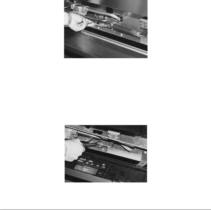
If the oven door is not closing properly, the door turnbuckle may require adjustment. To adjust the turnbuckle, flip down the lower front kick panel. The turnbuckle is connected between the rightand left-hand door springs (Fig. 1). With your hand, rotate the cast center piece of the turnbuckle two rotations at a time, then check the door tension. Repeat this procedure until the door works as desired. After adjustment has been made, tighten the locknuts.
Fig. 1
2A. 24L Oven Door J-Bolt Assembly
If the oven door is not closing properly, the door J-bolt assembly may require adjustment. To adjust the J-bolt assembly, flip down the lower front kick panel. The J-bolt assembly is connected to the right-hand bell crank arm (Fig. 2). The adjustment is made by the two 1⁄4-20 locknuts. Turn each nut in a clockwise direction to increase tension on the door; turn each nut in a counterclockwise direction to decrease the tension. Repeat this procedure until door works as desired. After adjustment has been made, tighten the locknuts.
Fig. 2
– 8 –
SERVICING SIMPLE CHECKS AND ADJUSTMENTS (Cont.)
3. Pilot Flame Height
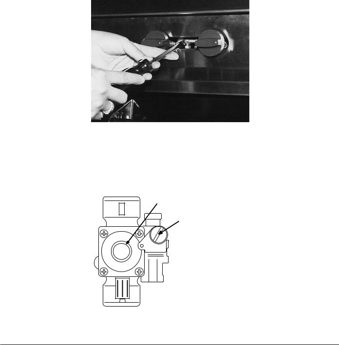
TOOLS REQUIRED: Standard flat blade screwdriver.
Top Burners: To adjust pilot flame height of the unit top burners, locate the pilot adjustment screws found on the front manifold pipe. It is not necessary to remove the manifold cover, as adjustment access holes have been provided in the panel. With screwdriver, turn the adjustment screw of the pilot valve experiencing the pilot flame height problems (Fig. 3). Rotate the screw clockwise to decrease and counterclockwise to increase the flame height.
Fig. 3
Oven: On rare occasions, the oven pilot may need adjustment. To do this:
1. Remove the pilot adjustment cap (Fig. 4)
|
|
B |
E |
R T |
|
O |
|
|
|
R |
|
|
|
|
|
|
|
|
C |
R |
|
|
|
A |
|
Y |
S |
|
|
|
H |
|
|
A |
|
|
|
W |
S |
O |
N |
|
||
|
|
|
IN
OUT
Oven Pilot
Control Button
Pilot Adjustment Cap
PL-50117
Fig. 4
– 9 –
SERVICING SIMPLE CHECKS AND ADJUSTMENTS (Cont.)
2.With screwdriver, adjust pilot key (located under pilot adjustment cap) to provide the proper size flame.
3.Replace pilot adjustment cap.
NOTE: If unit still is not heating correctly, refer to THERMOSTAT ADJUSTMENTS on Page 18.
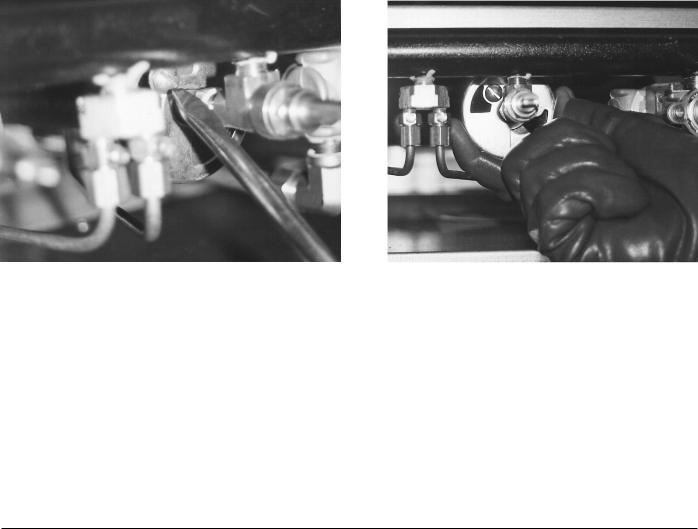
4.Air Shutter Adjustment
TOOLS REQUIRED: Standard flat blade screwdriver.
The efficiency of the oven depends on a delicate balance between the air supply and the volume of gas. Whenever this balance is disturbed, poor operating characteristics and excessive gas consumption will occur.
The gas mixer balance is controlled by an air shutter on the front of the oven burner. A yellow streaming flame on the burner is an indication of insufficient air. To correct this condition, loosen the screw locking the shutter into position. Rotate the air shutter open until the burner flame begins to lift from the burner, then close the shutter slightly down again and lock it into place (Fig’s. 5 & 6).
Fig. 5 |
Fig. 6 |
– 10 –
GAS CONNECTIONS
CAUTION: All gas supply connections and any pipe joint compound used must be resistant to the action of propane gases.
Each unit is factory-equipped with the type gas specified on the rating plate. The installation gas connection is a 3⁄4" (19mm) 14 FPT thread ANSI schedule #40 standard pipe.
Codes require that a gas shutoff valve be installed in the gas line ahead of the range.
Standard units are equipped with fixed burner orifices which coincide with the proper unit operation elevation. See Orifice Size Requirements for Different Elevations on Page 12. NOTE: Do not attempt to drill out orifice sizes. Obtain proper conversion kit from Vulcan-Hart depot.
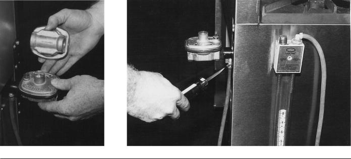
Install the gas pressure regulator.
NOTE: Before installing, check regulator supplied against unit rating plate gas supply.
As of 7/11/90, the gas pressure regulator is NOT factory installed to this equipment. The regulator for this unit gas type is sealed within a plastic bag attached to the oven rack inside the oven cavity. This regulator must be field installed by a qualified installation/service representative. The installer must adhere to all installation and pressure testing codes outlined in the Installation and Operation manual (supplied with the equipment), and local installation ordinances.
Natural gas regulators are preset for 3.7" W.C. (Water Column) (.92 kPa); propane gas regulators for 10.0" W.C.(2.5 kPa).
1.Locate 3⁄4" (19mm) gas connection pipe extending from rear of range.
2.Cover pipe threads with leak sealant.
3.Screw regulator hand-tight onto pipe with regulator arrow pointing towards range body back (see Fig. 7).
4.Using pipe wrench, tighten regulator securely in an upright position (see Fig. 7).
The arrow on the regulator shows the direction of the gas flow (Fig. 7). While connecting the range to the gas supply, the pressure regulator must be mounted horizontally to ensure proper preset outlet pressure. If the regulator is reinstalled in any other position, the outlet pressure must be reset (Fig. 8).
Fig. 7 |
Fig. 8 |
– 11 –
GAS CONNECTIONS (Cont.)
NOTE: A leak limiter is supplied with every regulator to allow excess gas pressure to escape. Do not obstruct leak limiter on gas pressure regulator as obstruction may cause regulator to malfunction.
WARNING: PRIOR TO LIGHTING, CHECK ALL JOINTS IN THE GAS SUPPLY LINE FOR LEAKS. USE SOAP AND WATER SOLUTION. DO NOT USE AN OPEN FLAME.
After piping has been checked for leaks, all piping receiving gas should be fully purged to remove air.
TESTING THE GAS SUPPLY SYSTEM
IMPORTANT: When test pressures exceed 1⁄2 psig (3.45 kPa), the range and its individual shutoff valve must be disconnected from the gas supply piping system.
When test pressures are 1⁄2 psig (3.45 kPa) or less, the range must be isolated from the gas supply system by closing its individual manual shutoff valve.
ORIFICE SIZE REQUIREMENTS
FOR DIFFERENT ELEVATIONS
FOR RESTAURANT RANGE
|
|
OPEN TOP |
HOT TOP |
GRIDDLE |
BRO/GRID |
OVEN |
|
|
|
|
|
(STD) |
|
|
INPUT AT SEA LEVEL |
|
|
|
|
|
|
17,500 |
20,000 |
15,000 |
10,000 |
30,000 |
|
|
PER BURNER (BTU’S) |
5.124 kW |
5.856 kW |
4.392 kW |
2.928 kW |
8.784 kW |
|
|
|
|
|
|
|
|
ORIFICE SIZE |
NAT/PROP |
NAT/PROP |
NAT/PROP |
NAT/PROP |
NAT/PROP |
|
|
|
|
|
|
|
|
SEA LEVEL |
Drill |
Drill |
Drill |
Drill |
Drill |
|
47/56 |
44/55 |
48/57 |
52/62 |
36/52 |
|
|
TO |
|||||
|
mm |
mm |
mm |
mm |
mm |
|
|
2000 FT |
|||||
|
2.00/1.5 |
2.20/1.35 |
1.95/1.10 |
1.60/1.00 |
2.7/1.60 |
|
|
|
|||||
|
|
|
|
|
|
|
|
2000 FT |
Drill |
Drill |
Drill |
Drill |
Drill |
|
48/56 |
45/55 |
49/58 |
53/65 |
39/53 |
|
|
TO |
|||||
|
mm |
mm |
mm |
mm |
mm |
|
|
4000 FT |
|||||
|
1.95/1.15 |
2.10/1.35 |
1.85/1.05 |
1.50/0.9 |
2.50/1.50 |
|
|
|
|||||
|
|
|
|
|
|
|
|
4000 FT |
Drill |
Drill |
Drill |
Drill |
Drill |
|
49/57 |
46/56 |
50/60 |
53/66 |
40/54 |
|
|
TO |
|||||
|
mm |
mm |
mm |
mm |
mm |
|
|
6000 FT |
|||||
|
1.48/1.10 |
2.05/1.15 |
1.80/1.00 |
1.50/0.8 |
2.50/1.40 |
|
|
|
|||||
|
|
|
|
|
|
|
|
6000 FT |
Drill |
Drill |
Drill |
Drill |
Drill |
|
50/58 |
47/57 |
51/63 |
54/67 |
41/55 |
|
|
TO |
|||||
|
mm |
mm |
mm |
mm |
mm |
|
|
8000 FT |
|||||
|
1.80/1.05 |
2.00/1.10 |
1.70/0.9 |
1.40/0.8 |
2.45/1.35 |
|
|
|
|||||
|
|
|
|
|
|
|
– 12 –
 Loading...