


Foreword
G700B
OPERATOR’S MANUAL
This Operator’s Manual is intended as a guide for the correct
use and maintenance of the machine. Therefore, study it
carefully before starting and operating the machine, or before carrying out any preventive maintenance.
Keep the manual in the manual box in the cab so that it is always at hand. Replace it immediately if it is lost.
NOTE: The manual describes the applications for which
the machine is primarily intended, and is written to apply for all markets. We therefore ask you to disregard the
sections that are not applicable to your machine or to
the work for which you use your machine.
Many hours are spent on design and production to make a
machine that is as efficient and safe as possible. The accidents that occur in spite of this are mostly caused by the human factor. A safety-conscious person and a well maintained
machine make a safe, efficient and profitable combination.
Therefore, read the safety instructions and follow them.
Every new Volvo Motor Grader is shipped with a CIMA Grad-
er Safety Manual published by the Construction Industry
Manufacturers’ Association. Read it carefully before operating or servicing your grader.
We continually strive to improve our products and to make
them more efficient through changes to their design. We retain the right to make these changes without committing ourselves to introducing these improvements on products that
have already been delivered.
We also retain the right to change data and equipment, as
well as instructions for service and maintenance, without prior notice.
Contents
Presentation
Instrument panels
Controls
Operating instructions
Operating techniques
SAFETY REGULATIONS
It is the operator’s obligation to know and follow the applicable national and local safety regulations. The safety instructions in this manual only apply to cases when there are no
national or local regulations.
WARNING!
The symbol above appears at various points in the
manual together with warning text. It means – Warning,
be alert! Your safety is involved. It is the obligation of
the operator to make sure that all warning decals are in
place on the machine and that they are readable.
Accidents may otherwise occur.
Know the capacity and limits of your machine!
This manual applies to Serial Number 35000 and up.
Safety when servicing
Service and maintenance
Specifications
Alphabetical index
Ref. No.: 21 1 434 4006
Printed in Canada

Foreword
2
State the PIN number of the machine (serial number) below. Always state this information when contacting the manufacturer and when ordering spare parts. It is also a good idea to note the serial number of the components.
Manufacturer Volvo Motor Graders Limited
160 Maitland Road,
Goderich, Ontario, Canada N7A 3Y6
The PIN number of the
machine (serial number)
Engine
Transmission
Final drive

Foreword
Operation and maintenance of the machine 3
Operation and maintenance of the machine
Volvo Motor Graders Limited is only responsible if:
n the machine has been used in a correct way and has been maintained
in accordance with the instructions in the Operator’s Manual and
Service Manual.
n prescribed service and prescribed inspections have been carried out
at the stated points of time.
n the recommended lubricants according to the manual have been
used.
n no security seals have been broken other than by authorized persons.
n all modifications and repairs have been carried out and methods have
been used in the way prescribed by Volvo Motor Graders Limited.
n only genuine Volvo spare parts/accessories, or genuine spare parts/
accessories that meet Volvo’s requirements, have been used.
WARNING!
The operator of a motor grader must have sufficient knowledge
and instructions before he/she operates the machine. Untrained
operators may cause severe injuries or even fatalities. Therefore,
it is important that you read and follow the instructions of this
Operator’s Manual. Never use a motor grader that has no
Operator’s Manual available. Learn and understand the safety
signs and symbols on the machine and the operator instructions
before you begin to use the machine.

Foreword
4 Communication equipment, installation
Communication equipment,
installation
IMPORTANT!
All installations of electronic communication equipment must be
performed by trained professionals and in accordance with Volvo
Construction Equipment instructions applicable to the specified
machine.
Protection from electromagnetic interference
The Volvo Motor Grader is equipped with multiple ECUs that were tested
for Electro Magnetic Compliance. This means that the ECUs are immune
to electromagnetic interference at the levels prescribed in the international standards. However, if improper installation and use of communication
equipment exceed the limits of these components, the machine may malfunction. Therefore, it is very important that all non-approved electronic
accessories, such as communication equipment, be tested before the
machine is put into service.
Mobile telephones
To obtain the best functionality, mobile telephones should be permanently installed in the electrical system of the grader with a permanently fixed
antenna on the cab, installed as advised by the manufacturer.
If a portable mobile telephone is used, note that it can constantly transmit
information to its base station, even when the telephone is not used. For
this reason, it should not be located beside electronic equipment in the
machine, such as directly on a control panel, etc.
Guidelines
The following guidelines must be followed during installation:
– The antenna placement must be chosen to give good adaptation to
the surroundings.
– The antenna cable must be of the coaxial type. Be careful to ensure
the cable is undamaged, that the sheath and braid are not split at the
ends, and the braid covers the connector ferrules and has good galvanic contact with them.
– The mating surface between the antenna mounting bracket and the
bodywork must have clean metal surfaces, with all dirt and oxide removed. Protect the mating surfaces against corrosion after installation
to maintain good galvanic contact.
– Remember to separate interfering and interfered cables physically. In-
terfering cables consist of the communication equipment’s supply cables and antenna cable. Interfered cables are those which are
connected to electronic devices in the machine. Install the cables as
close as possible to grounded sheet metal surfaces, since the metal
has a shielding effect.

Contents
Contents
Foreword.................................................................1
Operation and maintenance of the machine ......................3
Communication equipment, installation..............................4
Contents..................................................................5
Presentation ...........................................................7
General...............................................................................7
CE Marking and Declaration of Conformity ......................10
Plates and decals .............................................................12
Service .............................................................................16
General Information..........................................................17
Instrument panels ................................................21
General.............................................................................21
Center instrument panel ...................................................22
Pedestal instrument panel................................................28
Side console instrument panel .........................................45
All Wheel Drive control panel ...........................................52
Other ................................................................................54
5
Controls ................................................................55
Operator controls..............................................................55
Operator comfort ..............................................................57
Hydraulic controls .............................................................64
Other controls ...................................................................71
Operating instructions.........................................73
Introduction.......................................................................73
Running-in period .............................................................74
Safety and responsibility ..................................................75
Before operating ...............................................................80
Ignition switch ...................................................................83
Starting the engine ...........................................................85
Shifting gears ...................................................................87
Steering ............................................................................93
Braking .............................................................................95
Differential lock .................................................................97
After operating ..................................................................98
Towing............................................................................101
Transporting the machine...............................................103
Manual release of parking brake ....................................106
Moveable Blade Control System ....................................107
Scarifier ..........................................................................115
Ripper.............................................................................116
Windrow eliminator .........................................................117
Dozer blade/V-plow ........................................................119
One way plow.................................................................120
Hydraulic snow wing.......................................................121
Operating techniques ........................................123
Introduction.....................................................................123
Moldboard ......................................................................124
Turning around using articulation ...................................125
Making a three point turn................................................126

6
Contents
Grading around an object.............................................. 127
Grading on an ‘S’ curve shoulder .................................. 128
Right-hand leveling........................................................ 130
Left-hand leveling .......................................................... 131
Road construction.......................................................... 132
Scarifier and ripper operation ........................................ 143
Safety when servicing ...................................... 145
Introduction.................................................................... 145
Service position ............................................................. 146
General ......................................................................... 148
Fire prevention measures.............................................. 152
Hydraulic system ........................................................... 156
Electrical system............................................................ 159
Tires............................................................................... 160
Air conditioning unit ....................................................... 161
Fuel handling ................................................................. 162
Service and maintenance ................................. 163
Fuel system ................................................................... 165
Turbocharger ................................................................. 169
Engine air cleaner.......................................................... 170
Radiators and coolers.................................................... 172
Engine cooling system................................................... 174
Drive belt tension........................................................... 178
Electrical system............................................................ 179
Transmission ................................................................. 185
Engine clutch ................................................................. 187
Final drives .................................................................... 188
Tandems........................................................................ 190
Brake system................................................................. 191
Hydraulic system ........................................................... 193
All Wheel Drive .............................................................. 195
Tires............................................................................... 196
Climate control system .................................................. 197
Miscellaneous ................................................................ 200
Maintenance schedule................................................... 201
Grease points ................................................................ 202
Symbol key, lubrication and service chart ..................... 203
Lubrication and service chart......................................... 204
Specifications.................................................... 217
Recommended lubricants.............................................. 217
Capacities...................................................................... 219
Intervals between changes ............................................ 219
Engine ........................................................................... 221
Fuel system ................................................................... 223
Cooling system .............................................................. 224
Electrical system............................................................ 225
Power transmission ....................................................... 227
Brake system................................................................. 229
Hydraulic/Steering system ............................................. 230
Critical mounting torques ............................................... 231
Dimensional drawing ..................................................... 233
Noise and vibration levels.............................................. 234
Alphabetical index ......................................................... 235

Presentation
Presentation
General 7
General
Intended use
The machine is intended to be used under normal conditions for
the operations described in the Operator’s Manual. If it is used for
other purposes or in potentially dangerous environments, for example, an explosive atmosphere, areas with dust containing asbestos, etc., special safety regulations must be followed and the
machine must be equipped for such use. Contact the manufacturer or dealer for further information.
Engine
The engine is a four stroke cycle, in line six cylinder, turbocharged
diesel with overhead valves and air-to-air charge air cooler. These
engines are of the low emission type and all models have VHP
(Variable horsepower).
VHP
All Volvo grader models have engines that provide 2 different power levels depending on the gear selected by the operator.
– For non-All Wheel Drive equipped graders, forward gears 1,
2, and reverse 1, have reduced power to minimize wheel slip.
In forward gears 3 through 8, and reverse gears 2 through 4,
engine power is automatically increased.
– For All Wheel Drive equipped models with the All Wheel Drive
system turned OFF, the function of the VHP is the same as
above.
– For All Wheel Drive equipped models with the All Wheel Drive
turned ON, the engine power is increased for all gears.
– There is no operator selectable control over the VHP system.

Presentation
8 General
Electrical system
The electrical system is a 24VDC, negative-ground system. Power is supplied by two 12VDC batteries connected in series. Battery
charging is accomplished using a standard 75 amp alternator and
an optional 100 amp alternator. Electrical power can be disconnected using a ground isolation switch.
Clutch
A multiple wet disc clutch is mounted to the engine flywheel and
connected to the transmission with a driveshaft. The clutch must
be used when starting to move or when changing direction.
Transmission
The transmission has eight forward and four reverse speeds. It is
a fully sequential, direct drive, powershift unit utilizing a countershaft design.
Final drive/tandems
Final drives are single reduction in models G710B to G746B and
double reduction in the G780B. Each has an operator controlled
lock/unlock differential. Rear axles are case hardened, full floating
design, supported on double row spherical roller bearings. Tandem wheels are chain-driven.
Brakes
Hydraulically actuated, oil disc service brakes are located at the
four tandem drive wheels. The crossover dual braking circuits provide even braking on both sides of the grader.
If the engine stalls, or hydraulic boost pressure becomes unavailable, full braking capability is available through a reserve system.
An electric motor supplies the power required to bring the grader
to a safe stop.
The parking brake is a spring apply/hydraulic release, disc-type
brake. It is driveline-mounted to the transmission output shaft. An
accumulator in the circuit stores system pressure allowing the
brakes to remain released in the event of system pressure loss for
about 15 minutes.
Steering
The steering system is a closed-center dynamic signal load sensing system. The hydraulic steering system incorporates two steering cylinders. The leaning wheel feature and articulated frame can
be used to decrease turning radius. There is no manual steering.
Cab and frame
Both the canopy and fully-enclosed cab are equipped according to
the ROPS standard. FOPS approved structures are optional. Enclosed cabs are also provided with air conditioning and/or heating
systems as options. All controls are housed in the fully adjustable
steering pedestal and the right-hand side console. Ergonomic
seating and hydraulic control lever placement ensure operator
comfort and efficiency. The frame articulates 22° to the left or to
the right and uses anti-drift lock valves to ensure stable operation.

Presentation
General 9
MBCS (Moveable Blade Control System)
Blade mobility permits steep ditch cutting angles and back sloping
outside of overall machine width. The circle is held in place by adjustable clamp plates and guide shoes. Bearing surfaces are DURAMIDE™-faced to maximize service life. Hardened teeth are cut
on the outside of the circle. Oil is directed to the two drive cylinders
by a circle timing valve. The cylinders are arranged 90° out of
phase to ensure consistent power. The moldboard is provided with
replaceable cutting edge and end-bits. The drawbar is a narrow
“T” design for optimum visibility to the work area.
Hydraulic system
The closed-center hydraulic system uses a pressure and flow
compensated (load-sensing) variable displacement piston pump.
The pump supplies oil to the implements, the steering and the engine cooling fan system.
The cooling fan is driven by a fixed displacement vane-type motor.
Fan speed is variable and is determined by various cooling requirements. The fan operates between pre-determined minimum
and maximum speeds. The fan remains at its minimum speed until
there is a demand for cooling. Fan speed will automatically increase with the demand for cooling.
Lock valves (counterbalance valves) are incorporated into the
blade lift, moldboard tilt, circle shift, wheel lean and articulation circuits to prevent cylinder drift. The control levers are short throw,
feathering type located on an adjustable steering pedestal.
All Wheel Drive
G726B and G746B are All Wheel Drive models. The system operates in gears 1 through 7. It is powered by two electronically controlled, variable displacement hydraulic pumps in a closed loop
system. Each pump supplies one front wheel motor.
Front wheel motors are two-speed, high torque, radial piston, cam
lobe type. Each wheel motor has a separate speed sensor.
The system has a 16-speed aggression control dial.
Equipment and attachments
The circle, drawbar and moldboard equipment is fully maneuverable using hydraulic cylinders. Optional attachments include:
– Dozer blade
– Rear-mounted ripper-scarifier
– Mid-mounted scarifier
– Front-mounted scarifier
– Windrow eliminator
– Push block (counterweight for ripper)
– One-way plow
–V-plow
– Hydraulic snow wing (high and low bench)
– A-frame (used with V-plow and One-way plow only)
Presentation
10 CE Marking and Declaration of Conformity
CE Marking and Declaration of Conformity
(Only applies to machines marketed within the EU/EEA).
This machine is CE marked. This means that when delivered the
machine meets the applicable “Essential Health and Safety Requirements”, which are given in the EU Machinery Safety Directive.
If changes are made that affect the safety of the machine, the person carrying out the changes is responsible for the same.
As proof that the requirements are met, the machine is supplied
with an EU Declaration of Conformity, issued by Volvo Motor
Graders Limited for each separate machine. This EU Declaration
also covers attachments made by Volvo Motor Graders Limited.
This documentation is a valuable document, which should be kept
safe and retained for at least 10 years. The document should always accompany the machine when it is sold.
If the machine is used for other purposes or with other attachments than described in this manual, safety must at all times and
in each separate case be maintained. The person carrying out
such action is also responsible for the action that, in some cases,
may require a new CE marking and the issue of a new EU Declaration of Conformity.
EU EMC Directive
The electronic equipment of the machine may in some cases
cause interference to other electronic equipment, or suffer from
external electromagnetic interference, which may constitute safety risks.
The EU EMC directive on “Electromagnetic conformity” provides a
general description of what demands can be made on the machine out of a safety point of view, where permitted limits have
been determined and given according to international standards.
A machine or device, which meets the requirements, should be
CE marked. Our machines have been tested particularly for electromagnetic interference. The CE marking on the machine and the
declaration of conformity also covers the EMC directive.
If other electronic equipment is fitted to this machine, the equipment must be CE marked and tested on the machine as regards
to electromagnetic interference.

Presentation
CE Marking and Declaration of Conformity 11
Modifications
Modifications of any kind to this product including the fitting of unauthorized attachments, accessories, assemblies or parts could
affect the integrity of the product and/or the ability of the product
to perform as designed or intended.
It is policy that no modification of any kind is to be made to this
product unless officially approved by Volvo Motor Graders. A modification includes, but is not restricted to, the use of attachments,
accessories, assemblies and parts not approved by Volvo Motor
Graders and/or not installed in a factory approved manner.
Modifications are officially approved if at least one of the following
conditions is met:
1 The attachment, accessory, assembly or part is manufactured
or distributed by Volvo and installed in a factory approved manner as described in the publications available from Volvo; or
2 The modification has been approved in writing by the Engineer-
ing Department of Volvo Motor Graders.
Volvo Motor Graders disclaims responsibility for any situation that
may arise as a result of a non-approved modification. If any person or organization modifies or contributes in any way to a nonapproved modification, the person or organization will be deemed
to have assumed all the risks associated with such a modification,
including but not limited to, product failure, product damage, property damage, loss of production, injury or death.
If any claims result from a non-approved modification, Volvo Motor
Graders will protect its interest by taking whatever action is appropriate.
Volvo Motor Grader warranty shall not apply to any product or part
which fails or is damaged by, or whose functioning or operation is
adversely affected by non-approved modification.
Unauthorized modifications of the ROPS (Roll Over Protective Structure)
Never make any unauthorized alterations to the ROPS such as
lowering the height of the ceiling, drilling or welding to it.
Such unauthorized modifications will affect the structural limits of
the ROPS cab and will void the certification.
The ROPS has been approved after testing and meets the standard according to ISO 3471 1994 and SAE 1040 APR 88.
An optional cab has also been tested and approved according to
the FOPS (Falling Object Protective Structure) standard as defined by ISO 3449 1992, SAE J231 JAN 81 and meets the requirements for “Overhead guards for high-lift rider trucks” ISO 6055
1979 and “Operator seat belt requirements” SAE J386 JUN 93.
All planned alterations must be reviewed in advance by our Engineering Department to determine whether the alteration can be
made within the limits of the certifying tests.
It is important that all persons in your organization, including management, be made fully aware of these rules involving the ROPS.
Whenever anyone sees a machine ROPS with unauthorized alterations, both the customer and manufacturer should be notified in
writing.
Presentation
12 Plates and decals
Plates and decals
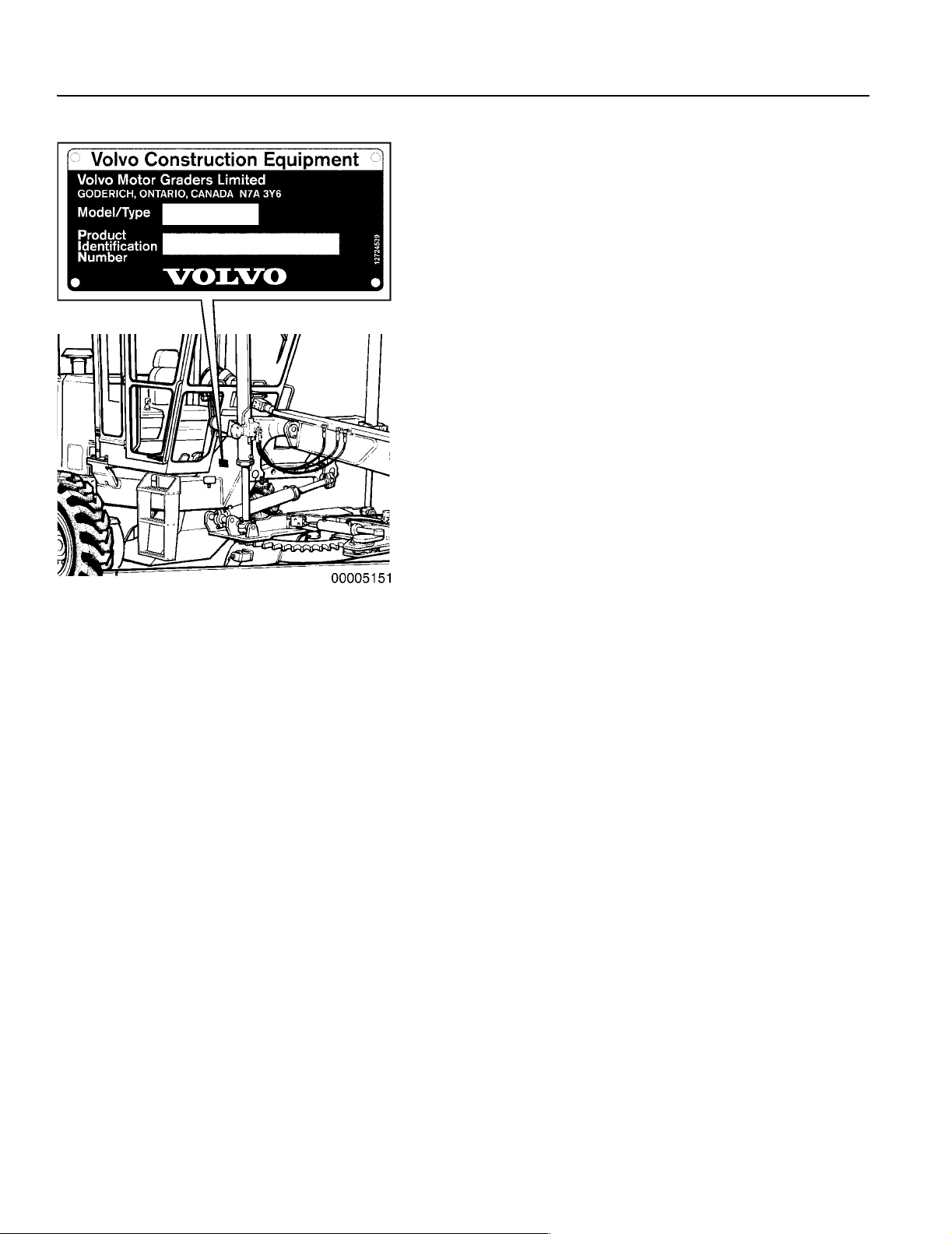
Product plates
The following illustrations and text show which product plates are
installed on the machine. These numbers are recorded at the factory.
Always quote the motor grader Model Number and the Product
Identification Number when ordering spare parts, and in all telephone inquiries or correspondence.
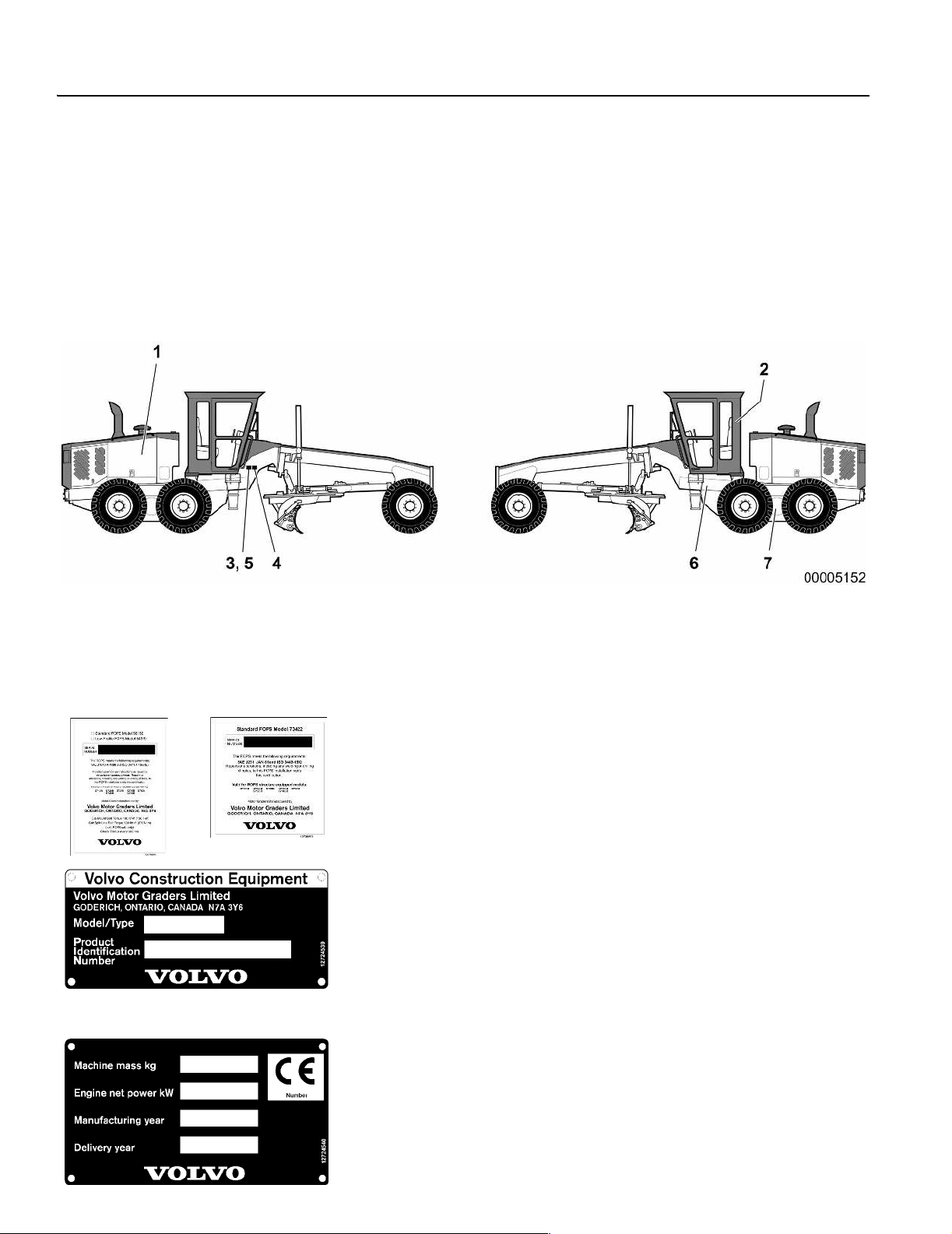
1 Engine
The engine serial numbers are found on a plate on the left-hand
side of the engine on models G710B to G730B. G740B, G746B
and G780B models have the serial number stamped into the righthand side of the engine block.
2 Cab
The ROPS and FOPS serial number plates are found inside the
cab on the left-hand post behind the operator’s seat. The ROPS
plate states the model and serial number, specification, maximum
machine mass, and bolt torque. The FOPS plate states the model,
serial number and specification.
3 Product identification plate
This plate is found on the right-hand side of the frame in front of
the cab. It has the Model Number and PIN (Product Identification
Number) stamped on it. The Model Number is broken down as follows: the first digit designates G700 Models; the next two digits indicate weight and horsepower range.
The Model Number and PIN must be used in conjunction with the
Parts Catalog to order correct replacement parts.
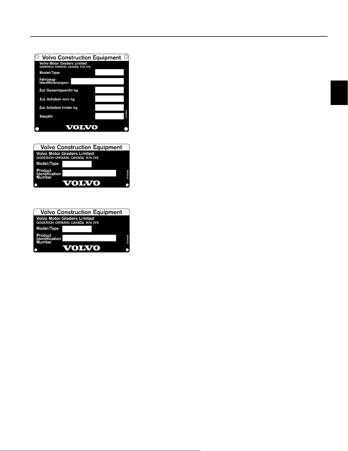
4 Product identification plate (EU/EEA countries)
In addition to the above information, this plate shows machine
weight, engine power, year of manufacture and has a space for
the CE mark. It also is positioned on the right-hand side of the
frame in front of the cab.
Presentation
Plates and decals 13
5 Product identification plate for TUV (Germany)
This plate is found on the right-hand side of the frame in front of
the cab.
6 Transmission
The transmission serial number is located on the lower front of the
housing.
7 Final drive
The final drive serial number is found on the right-hand side on the
rear of the final drive on models G710B to G746B. On G780B
models it is found on the top of the center housing.

Presentation
14 Plates and decals
Information and warning plates
The following illustrations and text show which safety signs can be
found on the machine. The operator of the machine must know
and follow warnings and information given on safety signs.
Safety signs that have been damaged, painted over, disappeared,
or for any other reason are no longer legible, must be replaced immediately.
The part number of the respective safety sign can be found in the
Parts Catalog.

Presentation
Plates and decals 15
Item Description Location
1 Warning! Hot components. Right-hand side, under the door latch of the engine compart-
ment door.
2 Warning! Never Short across starter
terminals.
3 24V Start On the starter, inside the engine compartment, right-hand side.
4 Warning! Hot pressurized coolant. On the top of the engine hood.
5 Warning! Crush zone. Both sides of the cab.
6 Parking brake decal Right-hand side of pedestal.
7 Warning! Wear seat belt when operat-
ing machine.
7 Warning! Read the operator’s manual
first!
8 Warning! Accumulator contents under
pressure.
9 Warning! Use only petroleum base fluid
in brake reservoir.
10 Warning! Crush zone. Both sides below the engine compartment door.
11 Differential lock operating instructions On the front windshield.
12 Anti-freeze coolant tag. On the steering wheel.
On the starter, inside the engine compartment, right-hand side.
Front of the pedestal.
Front of the pedestal.
Over the barrel of the accumulator (if equipped).
Rear right-hand side of cab.
13 Warning! Use no ether. On the engine hood beside the air intake.
14 Warning! Explosive gases. Inside the battery box, left-hand tandem case.
15 24V Start Inside the battery box, left-hand tandem case.
16 Safety instructions: Use handholds and
steps.
17 Warning! Keep clear of moldboard. On the left, right and rear faces of the drawbar.
18 Lubrication and service chart Left-hand side under the cab on the frame.
19 Warning! Rotating components. Right-hand side below engine compartment door. Both sides
20 Warning! Rotating fan. Inside of the rear radiator cowling door.
21 Sound decal
(Statement of exterior noise measurement of the machine)
Both sides of the cab.
inside the cooling compartment door.
On the right-hand side of the frame in front of the cab. (TUV,
EU/EEA countries only.)

Presentation
16 Service
Service
If the machine is to operate as economically as possible, it must
be properly maintained. Intervals of maintenance and lubrication
apply to the machine under normal environmental and operating
conditions. The maintenance work described in this manual can
be carried out by the operator. For further adjustments and repairs, the machine should be taken to an authorized dealer.
Delivery inspection
Before the machine left the factory it was tested and adjusted. In
addition to this, your dealer has carried out a further check – the
“Delivery Inspection” – according to our instructions before the
machine was handed over to you.
Inspection
It is especially important, however, that during the first period of
operation, the machine is subjected to further checks. Retightening of bolts, checking adjustments and other minor measures have
to be carried out. Carry out this inspection within 100 operating
hours.
Maintenance service
Condition Test and Maintenance Programs
In addition to the maintenance listed in the Maintenance Schedule
in this manual, your authorized dealer offers a maintenance system based on tests which give an indication of the general condition of your machine. Further information about this maintenance
system can be obtained from your nearest authorized dealer.

Presentation
General Information 17
General Information
The USA federal clean air act
The Federal Clean Air Act Section 203 (a) (3) states that the removal of air pollution control devices or the modification of an
EPA-certified non road engine to a non certified configuration.
The Federal regulations implementing the Clean Air Act for nonroad engines, 40 C.F.R. section 89.1003(a)(3)(i) reads as follows:
The following acts and the causing thereof are prohibited:
For a person to remove or render inoperative a device or ele-
ment of design installed on or in a non road engine vehicle or
equipment in compliance with regulations under this part prior to its sale and delivery to the ultimate purchaser or for a
person knowingly to remove or render inoperative such a device or element of design after the sale and delivery to the ultimate purchaser.
The law provides a penalty of up to $2,500 for each violation.
An example of a prohibited modification is the recalibration of the
fuel system so that the engine will exceed the certified horsepower
or torque.
You should not make a change to an EPA-certified non-road engine that would result in an engine that does not match the engine
configuration certified to meet the Federal Standards.
Customer assistance
Volvo Construction Equipment wishes to assure that the Emission
Control System Warranty is properly administered. In the event
that you do no receive the warranty service to which you believe
you are entitled under the Emission Control System Warranty, you
should contact your nearest Volvo Construction Equipment Regional office for assistance.

Presentation
18 General Information
Normal non-road engine use
The Maintenance Instructions are based on the assumption that
this conventional machine will be used as designated in the Operator's Instruction Manual and operated only with the specified fuel
and lubrication oils.
Non-road engine maintenance
The non-road engine is of conventional design and any local dealer may perform the necessary non-road engine emission control
maintenance defined in this manual.
Volvo recommends that the purchaser use the service program for
the non-road engine, known as Preventative Maintenance, including the recommended engine emission control maintenance.
In order to document that the proper regular maintenance has
been performed on the non-road engine, Volvo recommends that
the owner keep all records and receipts of such maintenance.
These records and receipts should be transferred to each subsequent purchaser of the non-road engine.
Service performed by your local dealer
Your local dealer is best qualified to give you good, dependable
service since he has trained service technicians and is equipped
with genuine original manufacturer's parts and special tools, as
well as the latest technical publications. Discuss your servicing
and maintenance requirements with your local dealer. He can tailor a maintenance program for your needs.
For regular scheduled service or maintenance, it is advisable to
contact your local dealer in advance to arrange for an appointment
to ensure availability of the correct equipment and service technician to work on your machine. This will aid your local dealer in efforts to decrease service time on your machine.

Presentation
General Information 19
Preventive maintenance program
To retain the dependability, noise level and exhaust emission control performance originally built into your conventional non-road
engine, it is essential that the non-road engine receive periodic
service, inspections, adjustments and maintenance.
Fuel system
Fuel Recommendations:
The fuel used must be clean, completely distilled, stable and noncorrosive. Distillation range, cetane level and sulfur content are
most important when selecting fuel for optimum combustion and
minimum wear.
Engine working conditions and ambient temperature influence the
selection of the fuel with respect to cold handling properties and
cetane levels.
In cold weather conditions, below 32 ºF (0 ºC), the use of lighter
distillate or higher cetane level fuel are recommended. (Final boiling point max. 660 ºF (349 ºC) and cetane min 45.)
To avoid excessive deposit formation and to minimize the emissions of sulfur dioxide into the ambient air, the sulfur content of the
fuel should be the lowest available. The diesel fuels recommended for use in Volvo engines should meet ASTM designation: D 975
No. ID (C-B) or No. 2D (T-T); with a cetane level above 42 and sulfur content not exceeding 0.5 percent by weight.
Check for fuel leaks (with the engine running at fast idle):
n Visually check unions and hose connections.
Check the condition of the fuel hoses for:
n Ageing
n Cracks
n Blisters
n Scuffing
Check the condition of the fuel tank:
n Drain water condensation.
n Check for cracks.
n Check for leaks.
n Check the mounting.
Check the turbocharger:
n Visually check for leaks in the intake hoses and exhaust pipe
of the turbocharger.

Presentation
20 Notes

Instrument panels
General 21
Instrument panels
General
WARNING!
Do not operate the machine until you are thoroughly
familiar with the position and function of the various
instruments and controls. Read this manual carefully.
Your safety is involved!
Glance at the instruments now and then. Doing so will alert you to
any abnormal readings and allow necessary action to prevent serious damage.
If any warning lamps or buzzers energize, park the machine and
shut down the engine immediately. Report the problem to your supervisor.
The battery isolation switch must be in the ON (I) position and the
ignition switch in the “I” position (running position) when checking
the function of the instruments and warning devices.
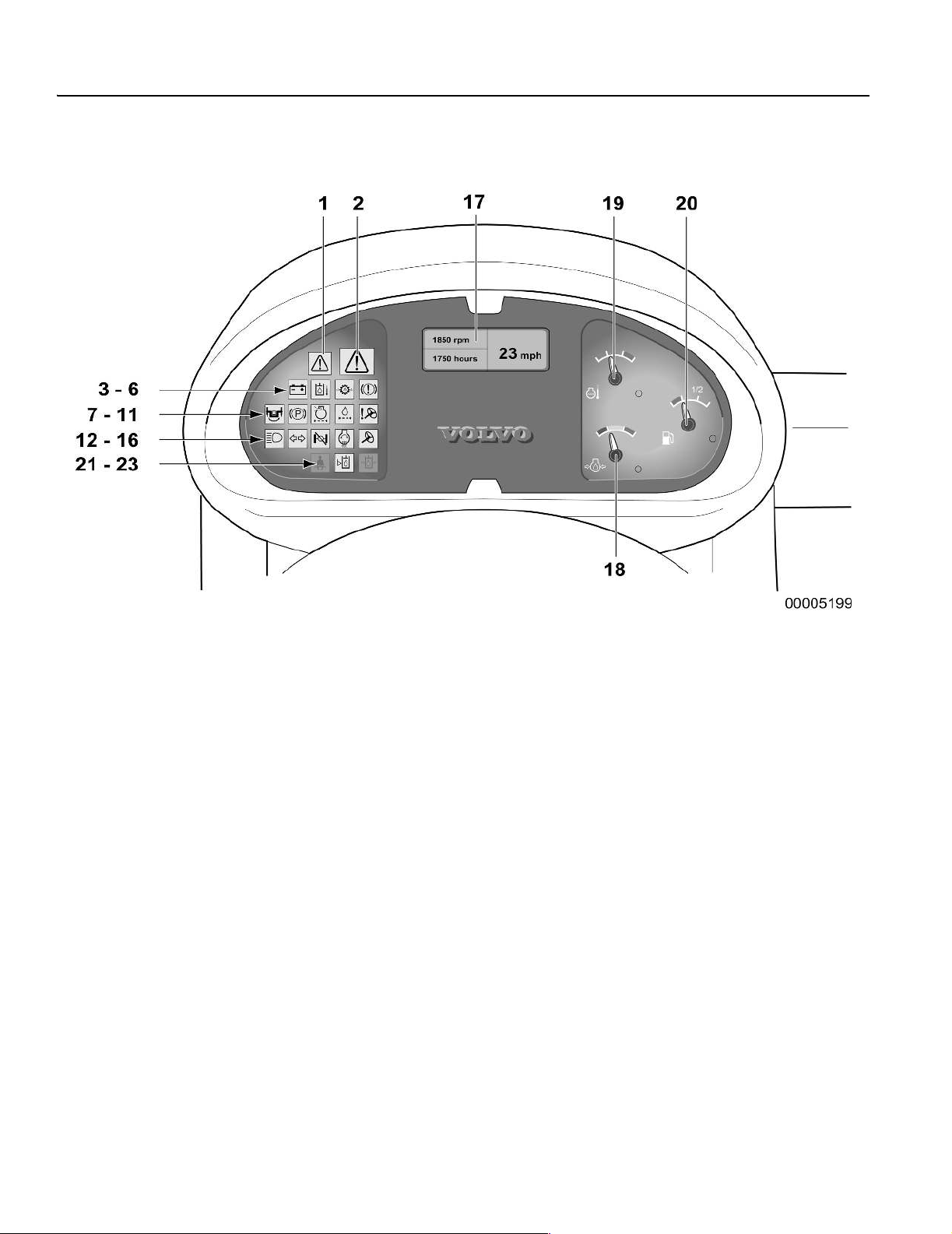
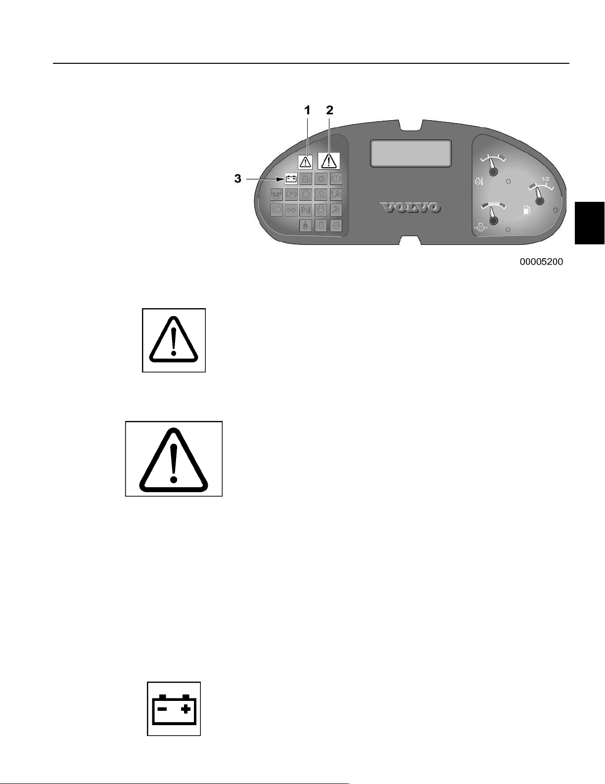
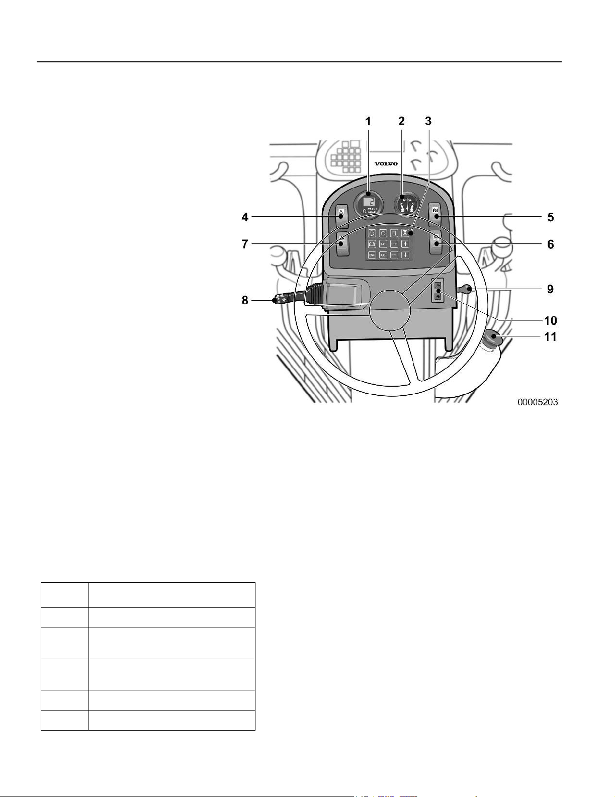
1 Center instrument panel (display unit, control lamps, gauges)
2 Pedestal head instrument panel (switches, warning lights, gauges)
3 Side console instrument panel (switches, warning lights/buzzers)
4 All Wheel Drive control panel (switches, warning/information lights, aggression dial)
Instrument panels
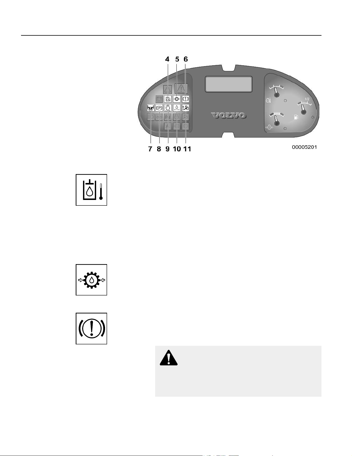
22 Center instrument panel
Center instrument panel
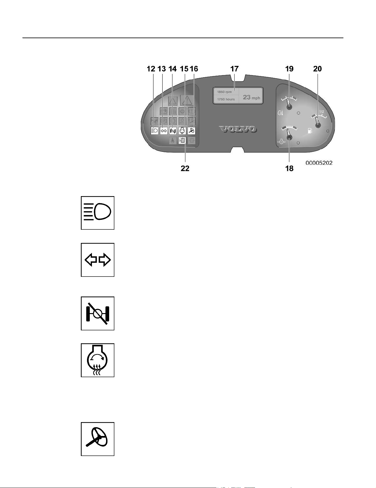
1 Information (amber) 12 High beams
2 Central warning (red) 13 Turn signal indicator
14 Differential locked
3 Charging battery 15 Engine preheat
4 High Hydraulic oil temperature 16 Secondary steering
5 Low transmission oil pressure
6 Brake warning 17 Display unit (speedometer optional)
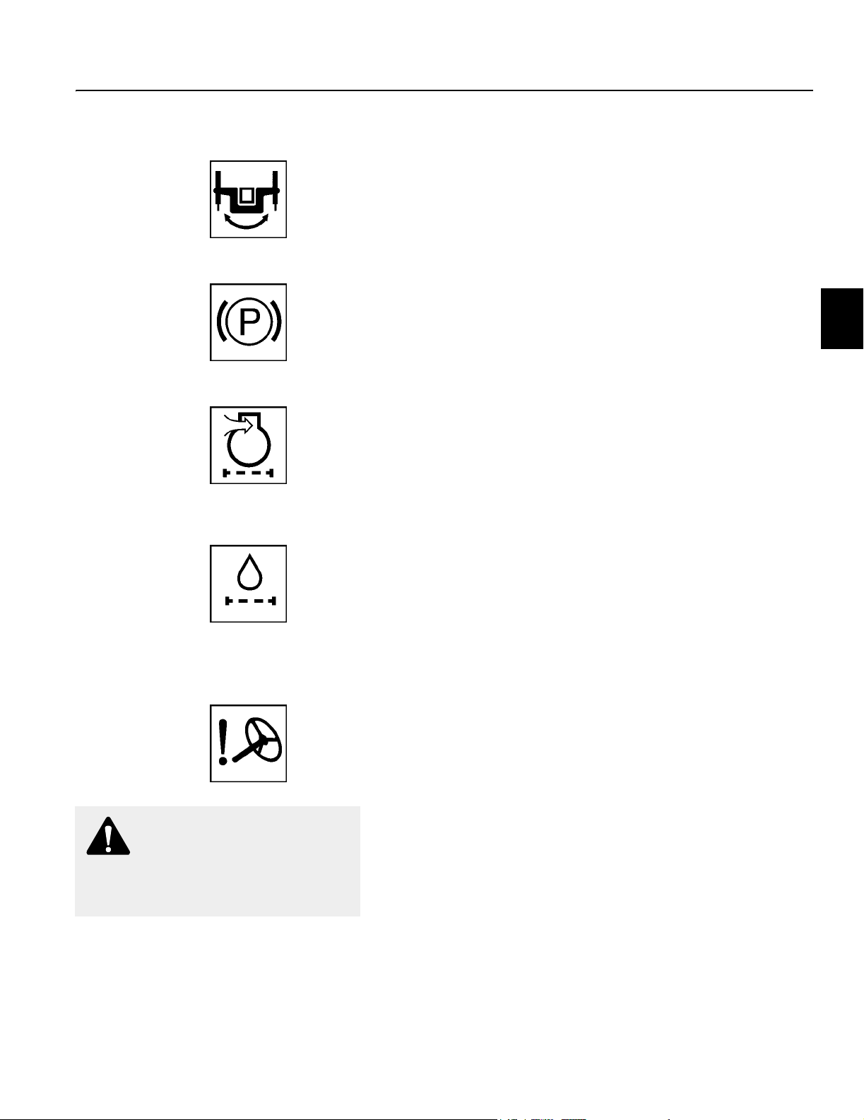
7 Blade control system unlocked 18 Engine oil pressure
8 Parking brake applied 19 Engine coolant temperature
9 Engine air filter restriction 20 Fuel level
10 Filter bypass warning
11 Primary steering system 21 (not used)
22 Hydraulic oil level
23 (not used)
General
If red control lamps light up – stop the machine immediately!
If amber lamps light up – an abnormal condition exists and mea-
sures may be required depending on the function concerned.
The remaining lamps – indicate that the respective function is
engaged/connected.
Instrument panels
Center instrument panel 23
1
Information (amber)
The amber central warning lamp flashes when system errors occur for less critical warnings. It informs the operator that a function
is engaged/disengaged or that a function needs to be kept under
observation (for example low fuel). It is accompanied by another
warning lamp and/or message display to clarify the warning/error.
2
Central warning (red)
The central warning lamp flashes when critical warnings or errors
occur. It is accompanied by a buzzer, another indicator lamp and/
or message on the display unit. It informs the operator that immediate attention is required.
Buzzer
The buzzer sounds at the same time the red central warning lamp
illuminates if any of the following faults are indicated:
– Low engine oil pressure
– Low transmission oil pressure
– Low parking/service brake pressure
– Parking brake (if applied in gear)
– Low hydraulic oil level
– Low steering system pressure
– High engine coolant temperature
– High hydraulic oil temperature
3
Battery charge warning (red)
This lamp is energized if the alternator is not charging. A message
is shown on the display unit if the electrical system voltage drops
below 21 volts or rises above 31 volts.
Instrument panels
24 Center instrument panel
4
Hydraulic oil temperature warning (red)
(optional)
This lamp indicates the hydraulic oil temperature in the reservoir
is too high. It is accompanied by the red central warning lamp,
buzzer, and display message.
Fluid temperature must be kept within acceptable limits in order to
retain its viscosity and other properties necessary for satisfactory
operation between oil change intervals. Refer to Service and
maintenance, Hydraulic system page 193 for further information.
5
Transmission pressure warning (red)
This lamp indicates low transmission oil pressure. It is accompanied by the red central warning lamp, buzzer, and display message.
6
Service brake warning (red)
This lamp indicates low brake system pressure or one of the brake
circuits is not functioning. It is accompanied by the red central
warning lamp, buzzer, and display message.
WARNING!
If the brake warning lamp and alarm energize during
grader operation, the brake system is faulty and must be
repaired by a qualified service technician. Do not drive the
grader.
Instrument panels
Center instrument panel 25
7
MBCS status lamp (amber)
The lamp indicates the MBCS (Moveable Blade Control System)
lock is disengaged.
107.
8
Parking brake applied (red)
This lamp indicates the parking brake is applied. If the brake is applied when the transmission is in gear, the lamp is accompanied
by the red central warning lamp, buzzer, and display message.
9
Engine air filter restriction (amber)
This lamp indicates restricted air flow through the engine air filter
and is accompanied by the amber central warning lamp. If this
lamp lights up, service or clean the engine air filter. Refer to Service and maintenance, Engine air filter elements page 170.
Refer to Moveable Blade Control System page
WARNING!
Operate the system only long enough
to make a steering correction –
maximum two minutes.
10
Filter bypass warning (amber)
(optional)
This lamp indicates either the transmission or hydraulic filter is
clogged. It is accompanied by a message in the display panel
identifying which filter is bypassing and the amber central warning
lamp.
11
Primary steering system (red)
(Secondary steering option only)
This lamp indicates low steering system hydraulic pressure. It is
accompanied by the red central warning, buzzer, and display message.
The Secondary steering option is an auxiliary hydraulic system
that allows the operator to make steering corrections more easily
in the event of loss of hydraulic flow to the steering unit. The ignition key must be in the “I” (running) position for this system to function. The system will also turn on when the test switch is activated,
see below.
Secondary steering system check
Refer to Secondary steering system test switch page 42.
Instrument panels
26 Center instrument panel
12
High beam (blue)
The blue control lamp is on when the high beam lights are on. Refer to the Directional indicator/High beam/Horn button page 43.
13
Directional indicators (green)
This lamp flashes when the directional indicator lever is moved for
turning left or right and when the 4-way hazard flasher switch is
activated.
14
Differential lock status (amber)
This lamp energizes when the differential lock is in the LOCK position.
15
Engine preheat (amber)
This lamp indicates the engine preheating element is on. Refer to
Side console instrument panel, Engine preheat switch page 49.
After 10 to 50 seconds (the time depends on the coolant temperature) the preheating element will be disconnected and the lamp
extinguished.
For cold starting instructions, refer to Starting the engine page 85.
16
Secondary steering system status (amber)
(Secondary steering option only)
This lamp will energize simultaneously with the Primary steering
system lamp. It indicates the secondary steering system has been
activated.

Instrument panels
Center instrument panel 27
17
Display unit
For display information, refer to the Pedestal head instruments,
Keypad, display unit page 30.
18
Engine oil pressure gauge
The pointer displays the current engine oil pressure. If the pointer
enters the red sector, the lamp beside the gauge will illuminate
along with the red central warning, buzzer, and display message.
19
Engine coolant temperature gauge
The pointer displays the current engine coolant temperature. If the
pointer enters the red sector, the lamp beside the gauge will illuminate along with the red central warning, buzzer, and display
message.
20
Fuel gauge
The gauge shows the current level in the fuel tank. Check your fuel
supply when the grader is on level ground. If the pointer moves
into the red area, the warning lamp will illuminate indicating the
machine should be refuelled. In this situation, there is approximately 17% of fuel capacity left. Refuel the machine to avoid air
entering the system.
If the tank has been run empty, see Bleeding the fuel system page
168
under Service and maintenance.
Fill the tank at the end of each shift. This reduces the chance of
condensation forming in the fuel tank.
For the capacity of the fuel tank, see Specifications, Capacities
page 219.
21
(not used)
22
Hydraulic oil level (red)
(optional)
This lamp illuminates when the hydraulic oil level is too low in the
reservoir. It is accompanied by the red central warning lamp, buzzer, and display message.
23
(not used)
Instrument panels
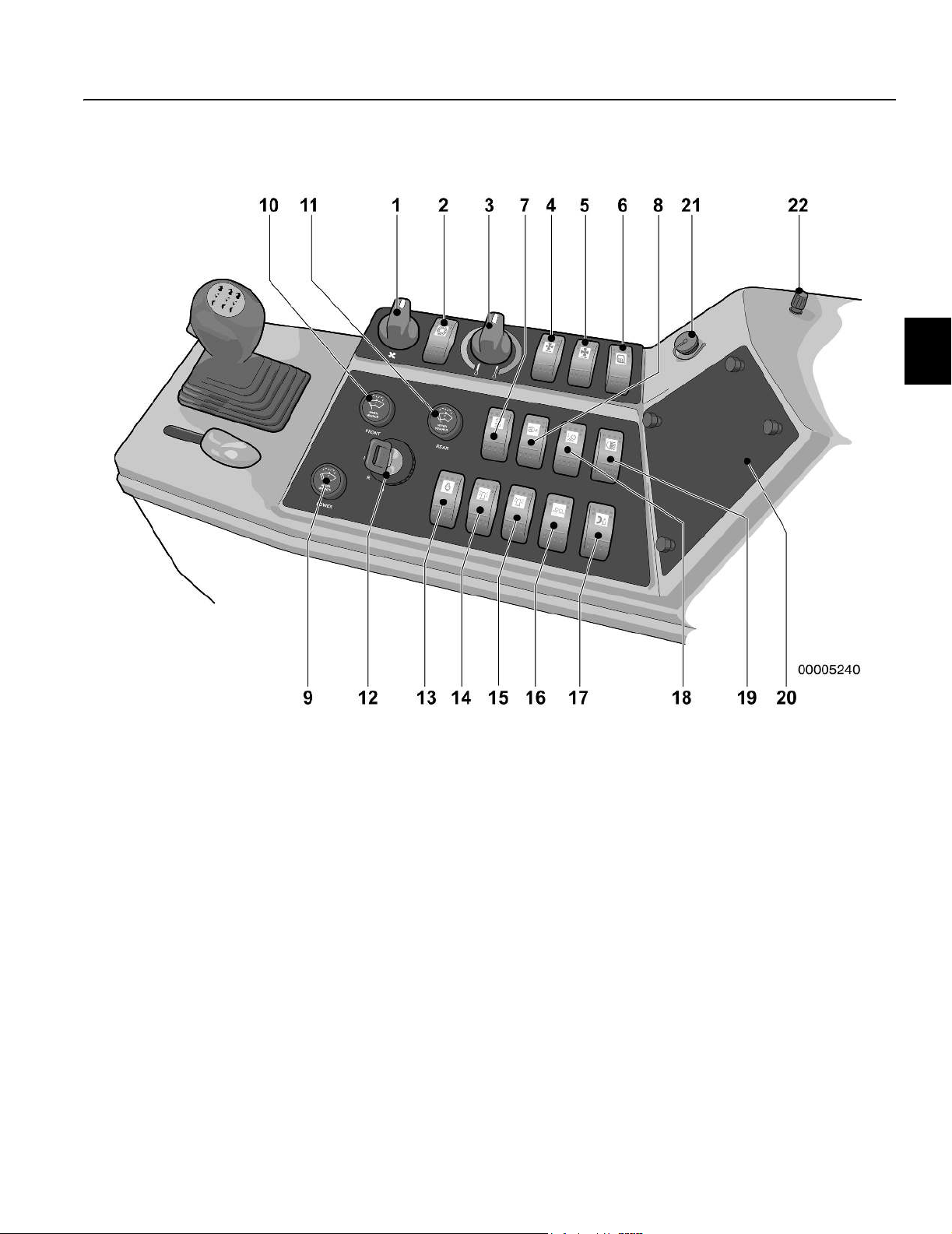
28 Pedestal instrument panel
Pedestal instrument panel
1 Transmission gear display 7 Secondary steering system test
2 Articulation indicator gauge 8 Directional indicator/ High beam/Horn
3 Keypad, display unit 9 Float valves power switch
4 Four-way hazard flasher 10 Float valves system indicator lights
5 Differential lock switch 11 Parking brake switch
6 MBCS lock pin
Code Meaning
.8.8 LCD (Liquid Crystal Display) test
7.8 ECU (Electronic Control Unit)
identification
8.4 ECU identification (All Wheel
Drive)
1 Last gear memorized* (example)
1
Transmission gear display
The transmission gear display is located in the top left-hand side
of the pedestal. It displays the transmission gear selected.
With the shift lever in the FORWARD position, the display shows
the number of the forward gear, for example ‘3’.
With the shift lever in the REVERSE position, the display shows a
negative number, for example ‘-2’.
Refer to Shifting gears page 87.
The gear display can also provide other information:
n It indicates a Start code sequence on start-up.
n It shows an error code if there is a fault in the transmission or
All Wheel Drive electrical system.
-1 Opposite gear* (example)
* Alternating display while in neutral
Start code sequence
When you start the engine, the transmission gear display will show
a series of codes called the Start code sequence.

Instrument panels
Pedestal instrument panel 29
Error codes
The transmission ECU (electronic control unit) continuously monitors the transmission and the AWD (All Wheel Drive) electrical
system. In the event of a malfunction in either of these systems,
an error code is shown in the gear display. Record any error
codes and have the electrical system repaired by a qualified
service technician. For further information on Error Codes,
see the Service manual.
Transmission error codes
If a malfunction occurs in the transmission electrical system, the
gear display shows the letter ‘E’ followed by a two-digit numeric
code. Multiple error codes are possible. The ECU disables the
transmission shifter and places the transmission in NEUTRAL.
The display alternates between ‘E’ and the code until the operator
returns the shift lever to the NEUTRAL position.
n “1.0” series error codes indicate insufficient power available
for transmission solenoids. The transmission will not operate until this problem has been resolved.
n “2.0” or “3.0” series error codes indicate either an open or
short circuit in a transmission solenoid. An alternate gear
can be selected by returning the transmission to NEUTRAL. This will allow the grader to be moved.
n “2.8” or “3.8” series error codes indicate either an open or
short circuit in the parking brake solenoid. The grader will not
operate until this problem has been resolved.
n “4.2” error code indicates the fault may be corrected by plac-
ing the shifter in NEUTRAL then back into gear.
n “4.4” error code indicates a multiple shift command error.
More than one proximity switch has been energized simultaneously. The circuit board must be replaced to correct this
problem.
n “4.6” error code indicates there is a problem with the shift le-
ver. The shift lever is out of neutral with no signal to the forward or reverse solenoids.
n “P” series error codes indicate a malfunction in the parking
brake electrical system.
AWD (All Wheel Drive) error codes
The transmission ECU continuously monitors the AWD electrical
system. It is able to detect abnormal conditions and alert the operator of a problem by displaying a code that will aid in correcting
the problem.
If a malfunction occurs:
1 The transmission gear display shows the letter “E” followed by
a 2-digit alphanumeric code. Multiple error codes are possible.
2 The display alternates between “E” and the error code until the
malfunction is corrected. The transmission is not disabled.
Record the error codes and have the AWD electrical system repaired by a qualified service technician. Some error codes will disable the AWD system.
NOTE! “L1”, “L2” and “L4” Series error codes indicate a serious
problem with hydraulic oil temperature, level or pressure. Shut the
grader down immediately and correct the problem.
Instrument panels
30 Pedestal instrument panel
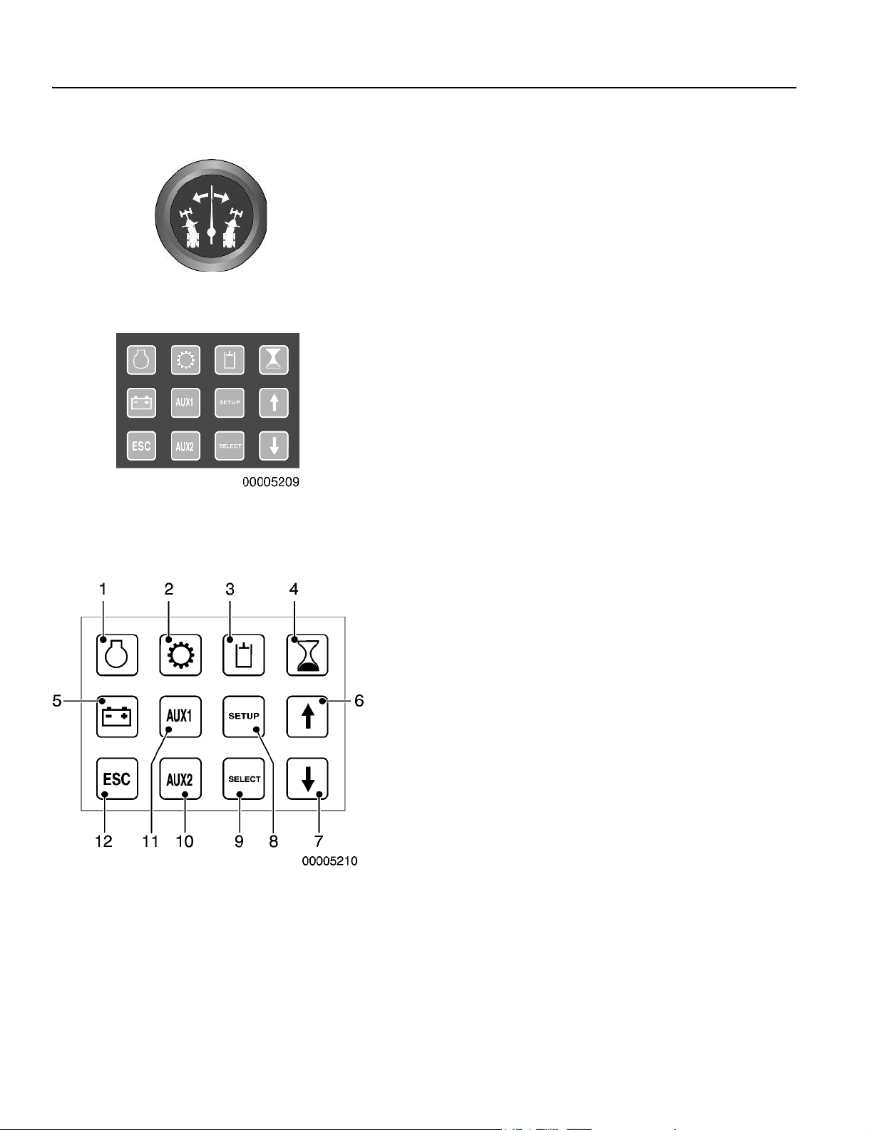
2
Articulation indicator gauge
The indicator needle displays the degree the grader frame is articulated. The frame is straight with the needle in the center position.
3
Keypad, display unit
The keypad allows access to information in different areas of the
grader. The information is organized into systems (function
groups).
Engine
Engine speed, Coolant temperature, Oil pressure, Air inlet temperature, Boost temperature, Boost pressure, Fuel temperature,
Fuel pressure (G740B, G746B and G780B only), Coolant level.
1Engine 7 Arrow down
2Transmission 8Setup
3Hydraulics 9Select
4 Hourmeter 10 Auxiliary 2
5 Electrical system 11 Auxiliary 1
6 Arrow up 12 Esc
Transmission
Transmission oil pressure, Filter bypass (optional), VHP status
Hydraulics
Brake pressure, Hydraulic filter bypass (optional), Hydraulic oil
temperature (optional), Hydraulic oil level (optional).
Electrical system
System voltage
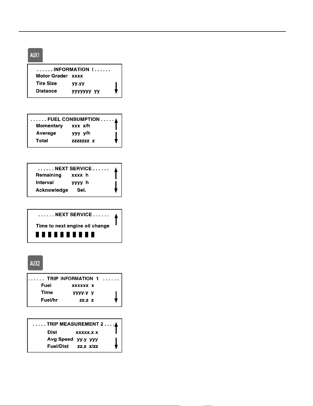
AUX1 (Grader information)
Model, Tire size, Distance (only with speedometer option), Instantaneous fuel consumption, Average fuel consumption, Total fuel
consumption, Time to next service, Next service interval.
AUX2 (Trip measurement information)
Fuel used, Time, Fuel/hour, Distance, Average speed, Fuel/distance, Reset (changes fuel, time and distance values to zero).

Instrument panels
Pedestal instrument panel 31
The following functions can be controlled from the keypad:
– Selecting function group by direct selection (function key)
– Browsing within a function group (the arrow keys)
– Activating/deactivating functions (on/off)
– Setting to zero/acknowledge (time/distance/cycles)
– Numerical settings (the arrow keys)
– Alpha-numerical settings (the arrow keys)
– Simpler settings (e.g. increase/reduce)
Engine, Transmission, Hydraulics, Hourmeter, Electrical,
Auxiliary 1 and Auxiliary 2 keys, display information about the
respective function group.
SETUP key displays the menu for making changes to units and
language. Refer to Setup, language and units page 34.
Arrow Up and Arrow Down keys are used to scroll in a function
group menu. Select key is used to change and confirm settings.
ESC key returns the display to “Operating display”, regardless of
which menu is showing.
When in the SETUP mode, pressing ESC will bring you back to
the top of the selected menu.
Refer to Setup, language and units page 34.

Instrument panels
32 Pedestal instrument panel
Display unit
Starting sequence (initial display)
(Ignition key in the “I” position)
The starting sequence takes about 4 to 5 seconds. At this time, a
test program runs to verify the system.
The progress of this test is indicated on the display unit by the appearance of black squares from 1 to 7.
During the first part of the test, the control lamps will light up and
the gauges will indicate (at twelve o’clock).
Displayed information
The display unit provides information to the operator. This information is divided into three groups:
1 Operating information, etc.
2 Warning displays (low pressure etc.)
Operating information display
3 ERROR displays (sensor and control device check)
1 Engine speed
2 Machine hours
3 Travel speed (optional)
4 Units for travel speed
Operating information display
n This is the default display.
n Obtain different information – engine, transmission, hydrau-
lics, hourmeter, electrical, auxiliary 1 and auxiliary 2 – by selecting buttons on the keypad.
Warning display
n Alerts the operator to a malfunction in machine systems (en-
gine, hydraulics, transmission, etc.).
n Applies to various areas of the grader.
Error display
n Alerts the operator to malfunction in the monitoring system.
n Applies to various areas of the grader.
Operating information (default display)
– Operating Information will be displayed after starting (unless
the operator had another display screen showing when the
power was switched off).
– At a speed above 20 km/h (12.4 mph) the Operating Informa-
tion will show the current travel speed (even if another display
screen was selected).
– If a display screen other than the Operating Information was
selected, the system will revert to that display screen when
the travel speed drops below 20 km/h (12.4 mph).
– Changing the display screen using the keyboard is only pos-
sible if the travel speed is below 20 km/h (12.4 mph).

Instrument panels
Pedestal instrument panel 33
Changing display screen
Move from one function group to another using the keys on the
keypad. When changing function group, the first menu of that
group will be displayed. To return to the Operating Information display, press the ESC key.
Setup
Settings of language and units are done in Setup, language
and units page 34.
Display classes
The information shown on the display for the operator is organized
into the following classes:
Class 1: WARNING
Shown regardless of which display is selected. “WARNING” display is shown for 2 seconds, then the previous display for 3 seconds. This is repeated for as long as the malfunction remains.
Generally, the red central warning lamp flashes while the alarm
text is shown.
Class 2: INFORMATION
Shown regardless of which display is selected. “INFO” display is
shown for 2 seconds, then the previous display for 3 seconds. This
is repeated until the info display has been shown 3 times.
Generally, the amber central warning lamp flashes while the info
display is shown.
The next time the machine is started, the info display is repeated
if it is still active.
Class 3: ERROR
Shown regardless of which display is selected. “ERROR” display
is shown for 2 seconds, then the previous display for 3 seconds.
This is repeated as long as the malfunction remains.
Generally, the amber central warning lamp flashes while the error
display is shown.
Class 4: SERVICE INFO
Shown regardless of which display is selected. “SERVICE INFO”
display is shown for 2 seconds, then the previous display for 3
seconds. This is repeated until acknowledged by “reset”.
Generally, the amber central warning lamp flashes while the service info display is shown.
Multi-info/warning/error display:
If several info/warning/error displays are active simultaneously,
they are shown one after the other.
Machines with the optional speedometer
At vehicle speeds greater than 20 km/h (12.4 mph), the info/warning/error display is shown first, then “Operating info” is shown,
then the next info/warning/error display, etc. At speeds less than
20 km/h (12.4 mph), the display information follows the sequence
described in its class, with the “previous” display shown between
the alternating multiple displays.
For machines not equipped with a speedometer, the information
displayed follows the sequence described in its class above, with
the “previous” display shown between the alternating multiple displays.

Instrument panels
34 Pedestal instrument panel
Setup, language and units
Language
– Depress the SETUP key, then depress the SELECT key to
– Select the required language with up or down arrow keys.
– After the language has been chosen, press SELECT. If no
Units
– By pressing the SELECT key, the display will change from the
– Choose the required units with the arrow keys and press SE-
– Press ESC to return to the main menu.
To cancel a setting, press ESC. The SETUP menu will appear.
Press ESC again to return to the main menu.
show the language menu. Available languages are English,
French, Spanish, Swedish, and German.
change of the setting is required, just press SELECT.
language menu to the menu for “Units”.
LECT. If no change of the setting is required, just press
SELECT.
Information display screens
Function groups
Each function group consists of one or more display screens. If
there is more than one screen for each function group, an arrow
pointing downward will be displayed in the bottom, right-hand
corner of the display. Arrows pointing upward and downward
indicate there are screens above and below the current one.
To browse within a function group, press the down or up arrow
keys.
NOTE! If “Er” is shown for a value in any display screen, it in-
dicates an error in the signal monitoring that information.
x = Engine speed (revolutions per minute).
y = Engine coolant temperature, units are °C or °F. Shown down
to 0 °C, below that shown as < 0 °C or < 0 °F.
z = Engine oil pressure, units are in bar or psi.
x = Intake air temperature, units are °C or °F. Indicates actual
temperature down to 0 °C, below that shown as < 0 °C or <
0 °F.
y = Charge air temperature, units are °C or °F. Indicates actual
temperature down to 0 °C, below that shown as < 0 °C or <
0 °F.
z = Charge air pressure, units are in bar or psi.
x = Fuel temperature, units are °C or °F. Indicates actual tem-
perature down to 0 °C, below that shown as < 0 °C or < 0 °F.
y = Fuel pressure, units are bar and psi.
z = Coolant level (normal or low).

Instrument panels
Pedestal instrument panel 35
x = Transmission oil pressure (indicates normal or low).
y = Transmission oil filter (indicates normal, clogged).
z = VHP status (indicates ON or OFF).
x = Brake system pressure (indicates normal or low).
y = Hydraulic oil filter (indicates normal or clogged).
z = Hydraulic oil temperature (indicates normal or high).
x = Time in hours, up to 99999.9.
x = Electrical system voltage (real time) in volts DC.
Instrument panels
36 Pedestal instrument panel
x = Machine model
y = Tire size designation
y = Distance travelled, units in km or mi. Shown up to
NOTE! Values for distance are only shown if the speedometer
option is installed on the machine.
x = Current fuel consumption, shown in L/h or g/h (liters per
y = Average fuel consumption per hour, shown in L/h or g/h (li-
z = Total fuel consumption, calculated up to 9999999 liters or
999,999 km or 621,372 miles.
hour or US gallons per hour).
ters per hour or US gallons per hour). Calculated by dividing
total fuel consumed by engine hours.
2641720 US gal, in one unit increments.
x = Time remaining to next service interval.
y = Service interval, shown as 250, 500, 1000, 2000. When 8
hours remain to next service, display shows “Time for service”.
To acknowledge and remove information, press SELECT.
The bars indicate the total time left until the next service interval.
Each one represents 25 hours.
When 8 hours remain to next service, the display shows “Time to
change engine oil”.
To acknowledge and remove information, press SELECT.
x = Fuel consumption since resetting, in liters or US gal up to
999,999 liters or 264,200 US gal.
y = Time since resetting in hours up to 9999.9
z = Fuel consumption per hour since resetting, up to 99.9 L/h or
26.4 US gal/hr.
NOTE! To reset, see Trip information reset to follow.
x = Total distance since resetting in km (or mi) up to 9999.9 km
(6213.6 mi), alternatively –
y = Average speed since resetting up to 99.9 kmh (62.1 mph)
shown in kmh (kilometre/hour) or mph (miles/hour), alternatively –
z = Fuel consumption per unit distance since resetting, up to
99.9 in L/km or US mi/gal, alternatively –
NOTE! Values based on distance only available with speedometer option. If speedometer not available, value displays
as “n/a”.

Instrument panels
Pedestal instrument panel 37
Trip information reset:
– Press AUX 2, display shows “TRIP INFORMATION 1”.
– Press the down arrow, display shows “TRIP
INFORMATION 2”.
– Press the down arrow, display shows “TRIP RESET”.
– Press SELECT to reset. The display shows “TRIP RESET –
RESETTING”.
– Trip data is now set to zero.
Warning displays
The following alarm texts may appear on the display unit.
ENGINE, warning and information displays
XXXX = PPID, PID, or SID
YYY = Numeric value 1 - 999
TRANSMISSION, warning and information displays

Instrument panels
38 Pedestal instrument panel
HYDRAULICS, warning and information displays
ELECTRICAL SYSTEM, warning and information displays
WARNING DISPLAYS, other

Instrument panels
Pedestal instrument panel 39
ERROR DISPLAYS, sensor and actuator switches, engine
XXXX = PPID, PID, or SID
YYY = Numeric value 1 - 999

Instrument panels
40 Pedestal instrument panel
ERROR DISPLAYS, sensor and actuator switches, transmission
ERROR DISPLAYS, sensor and actuator switches, hydraulics
ERROR DISPLAYS, sensor and actuator switches, other

Instrument panels
Pedestal instrument panel 41
4
4-way hazard flasher switch
Depress the top of the rocker switch to turn on the 4-way flashers.
Depress the bottom of the switch to turn them off.
The directional indicator lamp in the center display will flash when
the 4-way flashers are activated. The red indicator lamp on the
switch will flash when the flashers are activated.
5
Differential lock/unlock switch
The top of the rocker switch is depressed to activate the differential lock; the bottom of the switch is depressed to deactivate.
The differential lock status lamp in the center display panel and the
lamp on the switch energize when the differential lock is in the
LOCK position.
Put the control switch in the LOCK position for normal grading operations when maximum traction is required. Put the control
switch in the UNLOCK position when differential action is required.
This will reduce the turning radius and decrease tire scuffing when
operating on paved surfaces.
WARNING!
Lock or unlock the differential ONLY when driving at slow
speeds, in a straight line or if the grader is stopped. Do
not lock or unlock the differential while making a turn or
when the tandem wheels on one side are spinning.
Damage to the differential could result.
Instrument panels
42 Pedestal instrument panel
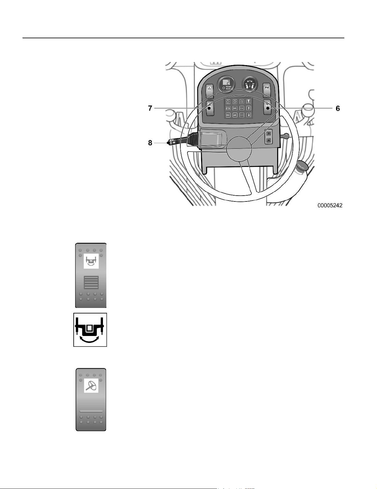
6
MBCS (Moveable Blade Control System)
lock pin switch
The switch has a secondary release to activate it and prevent involuntary release of the MBCS lock pin. Push up on the secondary
release and the top of the rocker switch to retract the pin. The
MBCS status lamp in the center display energizes to indicate that
the lock pin is retracted.
Push the bottom of the switch to engage the MBCS lock pin.
See also
Moveable Blade Control System page 107.
7
Secondary steering system test switch
(optional)
This is a momentary style switch. Push on the top of the switch to
activate and deactivate the system. The switch defaults to the off
position.
To test the Secondary steering system:
n Turn the ignition key to the “I” (running) position. Do not start
the engine.
n Depress the top of the rocker switch to activate the system.
The Red central warning lamp, Primary steering system lamp
and the Secondary steering lamp in the center instrument
panel will energize accompanied by a buzzer and display
message.

Instrument panels
Pedestal instrument panel 43
n Check the system by turning the steering wheel.
WARNING!
Do not operate the supplementary steering system longer
than two minutes. Equipment damage will result.
n If the steering wheel does not turn easily, there is a fault in the
system. Have the system repaired by a qualified service technician.
8
Directional indicator/High beam/Horn but-
ton
Directional indicator
Move the turn signal switch lever UP to activate the right-hand turn
signal. Move the turn signal switch lever DOWN to activate the
left-hand turn signal.
High beam
Pull the lever back towards the operator to change the headlights
from low beam to high beam and back. A blue lamp illuminates in
the display panel to indicate high beam.
Horn button
Push in on the end of the lever to sound the horn.

Instrument panels
44 Pedestal instrument panel
9
Float valves power switch
The float valve switch arms the float system for the moldboard and
attachments. This is a momentary style switch.
Push the power switch up to activate the system; push down to deactivate. Lights mounted on the front of the pedestal indicate that
the system is activated. See below.
WARNING!
Do not use float control to lower moldboard. Loss of
control of grader could result.
10
Front float valves system indicator lights
(control lamp amber)
These indicator lamps are mounted on the front right-hand side of
the pedestal. They illuminate when the Front float valve system is
active. If the option is not installed on the grader, the lamp will not
illuminate.
NOTE! If the valve is already in the float position (4th position
detent), and the floats have not been activated, move the lever out of the float position in order to activate the system.
11
Parking brake switch
Push in the knob to apply the parking brake; pull out to release it.
The switch must be pushed in (parking brake applied) to start the
grader.
Instrument panels
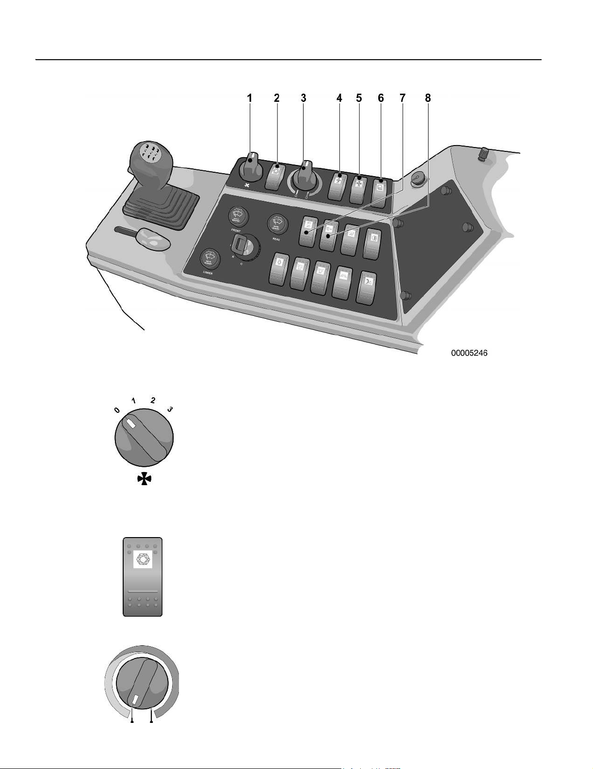
Side console instrument panel 45
Side console instrument panel
1 Heater/air conditioner fan speed switch 12 Ignition switch
2 Air conditioner switch 13 Engine preheat switch
3 Heater/air conditioner temperature control 14 Amber revolving beacon switch
4 Front defroster fan switch 15 Blue revolving beacon switch
5 Rear defroster fan switch 16 Wing lights switch
6 Heated mirrors switch 17 Tire pump switch
7 Headlights and parking light switch 18 Moldboard lights switch
8 Extra headlights or EEC headlights and parking lights switch 19 Rear flood lights switch
9 Lower windows wiper/washer 20 Fuse and relay center access panel
10 Front windshield wiper/washer 21 Socket for service display unit
11 Rear windshield wiper/washer 22 Instrument lighting level
23 24V Remote electrical receptacle (not
shown)
Instrument panels
46 Side console instrument panel
1
Heater air conditioner fan speed switch
(optional)
Turn the knob to increase or decrease the heater air/conditioner
fan speed.
0 = System off
1 = Low fan speed
2 = Medium fan speed
3 = High fan speed
2
Air conditioner switch
(optional)
The air conditioning system is turned on and off using the rocker
switch. Depress the top of the switch to turn the system on. Depress the bottom of the switch to turn it off. An indicator lamp in the
switch illuminates when the switch is activated.
3
Heater/air conditioner temperature control
(optional)
Turn the knob clockwise to raise the air temperature (warmer).
Turn it counterclockwise to lower the air temperature (cooler).

Instrument panels
Side console instrument panel 47
4
Front defroster fan switch
(optional)
This is a three position switch. Depress the top of the switch to position two to activate low speed. Depress the top of the switch
again to position three to activate high fan speed. Depress the bottom of the switch to turn it off.
5
Rear defroster fan switch
(optional)
This is a three position switch. Depress the top of the switch to position two to activate low speed. Depress the top of the switch
again to position three to activate high fan speed. Depress the bottom of the switch to turn it off.
6
Heated mirrors switch (optional)
Depress the top of the switch to activate the heated external cab
mirrors. An indicator lamp in the switch illuminates to show the
switch has been activated. Depress the bottom of the switch to
turn them off.
7
Headlights, EEC headlights and parking
lights switch
This is a three position rocker switch. Depress the top of the switch
to position two to turn on the parking lights only. Depress the top
of the switch to position three to turn on the front headlights along
with the parking lights. If the high beam lights are on, the blue control lamp in the center display panel will be on.
8
Extra headlights switch
(optional)
This switch is used for extra headlights. Depress the top of the
rocker switch to turn on these lights. Depress the bottom of the
switch to turn them off.

Instrument panels
48 Side console instrument panel
9
Lower windows wiper/washer
(optional)
The wiper switch has three positions. Move it clockwise one indexed position for normal speed. Move it two indexed positions for
fast speed. The windshield washer activates when the switch is
pushed (spring return). See also Windshield washer fluid reser-
voir, front and rear windows page 200
10
Front windshield wiper/washer
(optional)
The wiper switch has three positions. Move it clockwise one indexed position for normal speed. Move it two indexed positions for
fast speed. The windshield washer activates when the switch is
pushed (spring return).
11
Rear windshield wiper/washer
(optional)
The wiper switch has three positions. Move it clockwise one indexed position for normal speed. Move it two indexed positions for
fast speed. The windshield washer activates when the switch is
pushed (spring return).

Instrument panels
Side console instrument panel 49
12
Ignition switch
The Ignition switch has four positions.
O Turned off
R Radio position
I Running position and preheating position
II (not used)
III Starting position
See also Ignition switch page 83.
13
Engine preheat switch
This momentary style switch is used for connecting a heating element in the intake manifold.
To turn on the preheating element, turn the ignition key to the “I”
position. Depress and release the switch. The lamp in the center
instrument panel illuminates to indicate the element is connected.
Refer to Starting the engine page 85.
14 and 15 Amber and blue revolving beacon light
switches
(optional)
Depress the top end of the rocker switch to turn on the revolving
beacon. Depress the bottom end of the rocker switch to turn it off.
An indicator lamp on the switch illuminates when the switch is activated.
16
Wing lights switch (optional)
Depress the top end of the rocker switch to turn on the wing lights.
Depress the bottom of the switch to turn them off. An indicator
lamp on the switch illuminates when the switch is activated.
17
Tire pump switch (optional)
Depress the top end of the rocker switch to activate the tire pump.
Depress the bottom of the switch to turn it off. An indicator lamp
on the switch illuminates when the switch is activated.

Instrument panels
50 Side console instrument panel
18
Moldboard lights switch
(optional)
Depressing the top of the rocker switch turns on the moldboard
work lights. Depress the bottom of the switch to turn them off. An
indicator lamp on the switch illuminates when the switch is activated.
19
Rear flood lights switch
(optional)
Depressing the top of the rocker switch turns on the floodlights on
the rear of the machine. Depress the bottom of the switch to turn
them off. An indicator lamp on the switch illuminates when the
switch is activated.
Instrument panels
Side console instrument panel 51
20
Fuse and relay center access panel
The fuse panel is installed inside the console cover and contains
circuit breakers, fuses, relays, and the directional indicator flasher
unit. See Basic Preventive maintenance, Electrical system, Circuit
breakers and fuses page 183, for additional information.
If an electrical overload occurs:
n The button of the applicable circuit breaker extends to the
open position.
n The element of the applicable automotive blade-type fuse
melts.
To reconnect the electrical circuit:
n Press the circuit breaker button into the closed position.
n Find and discard the fuse with the broken element. Install a
new fuse having the same amperage rating.
NOTE! If the problem persists, have it repaired by a qualified
service technician.
21
Socket for service display unit
The service socket is positioned on the side console beside the
fuse access panel.
Contact an authorized dealer workshop.
22
Instrument lighting level
This control is used for regulating the intensity of the instrument
lighting (gauges and control lamps).
Turning the control to the right increases the light intensity.
NOTE! Switch 7 (Headlight switch) must be on.
23
24V Remote electrical receptacle
(Not shown in main overview illustration)
A remote 24 volt electrical receptacle is located on the front panel
of the right-hand side console.

Instrument panels
52 All Wheel Drive control panel
All Wheel Drive control panel
General
The All Wheel Drive control panel is mounted on the right-hand
side of the cab in the door post. It contains all the controls and
warning lamps needed to operate the All Wheel Drive system.
The All wheel Drive System is activated by a rocker switch on the
front of the control panel (7).
Green lamps indicate system (1) and Creep mode activation (4).
The control panel has additional lamps that warn of excessive oil
temperature (5), low charge pressure (6), low oil level (2) and
clogged filter (3). These lamps alert you that a problem exists. Low
oil level and low charge pressure lamps are accompanied by an
audible alarm.
At the bottom of the control panel is the All Wheel Drive 16-position aggression dial (9). This dial allows the operator to adjust the
power applied to the front wheels in comparison to the rear. For
further information on the operation of the All Wheel Drive system,
refer to Operating instructions, All Wheel Drive models page 91.
1 System activation lamp (green)
2 Low oil level lamp (red)
3 Oil filter clogged lamp (amber)
4 Creep mode activation lamp (green)
5 High oil temperature lamp (red)
6 Low oil pressure lamp (red)
7 System activation switch
8 Creep mode activation switch
9 All Wheel Drive aggression dial
Warning lamps
These warning lamps indicate a malfunction with the system. If
any of these lamps energize during normal operation of the All
Wheel Drive system and remain on, perform the following:
n Turn the system off.
n Stop the grader and report the malfunction.
n Investigate the cause.
n Have the system repaired by qualified service personnel.
n Do not attempt to use the All Wheel Drive system until the fault
is repaired.
1
System activation lamp
This lamp indicates the All Wheel Drive system is activated.
2
Low oil level lamp
This warning lamp will energize, the buzzer will sound and the system automatically shuts down when the oil level in the hydraulic oil
reservoir is too low.
3
Oil filter clogged lamp
This warning lamp will energize when the filter becomes clogged.
It may also energize during a cold start but will correct itself when
the oil temperature increases.

Instrument panels
All Wheel Drive control panel 53
4
Creep mode activation lamp
Indicates the Creep Mode has been activated.
5
High oil temperature
If the oil temperature increases above an acceptable level, the
high temperature warning lamp energizes and the system automatically shuts down.
6
Low oil pressure
If the All Wheel Drive hydraulic system charge pressure drops below a safe value, the charge pressure warning lamp energizes, the
buzzer sounds and the system automatically shuts down.
7
System activation switch
All Wheel Drive is available in gears 1 to 7. Push the top of the
rocker switch to engage the All Wheel Drive system. To deactivate
it, depress the bottom of the switch. For more information on the
use and function of the All Wheel Drive system,
structions, All Wheel Drive models page 91.
see Operating in-
8
Creep mode activation switch
Creep Mode is used for low speed, fine grading using the front
wheel drive only. It will operate at speeds from 0 to 3,2 km/h (0 to
2 mph) in forward and reverse. Creep mode is activated by depressing the top of the spring return rocker switch. It is deactivated
by pressing the top of the switch again. For more information on
the use and function of the All Wheel Drive system, see Operating
instructions, All Wheel Drive models page 91.
9
All Wheel Drive aggression dial
Different tractive conditions can be encountered by the front and
the rear of the machine. This will only occur when grading under
diverse conditions with the All Wheel Drive system engaged. The
16-position manual dial control is used to fine tune speed differences that may occur between the front and the rear wheels.
n A lower setting slows the front wheel rotational speed com-
pared to the rear; a higher setting increases the front wheel rotational speed in comparison to the rear.
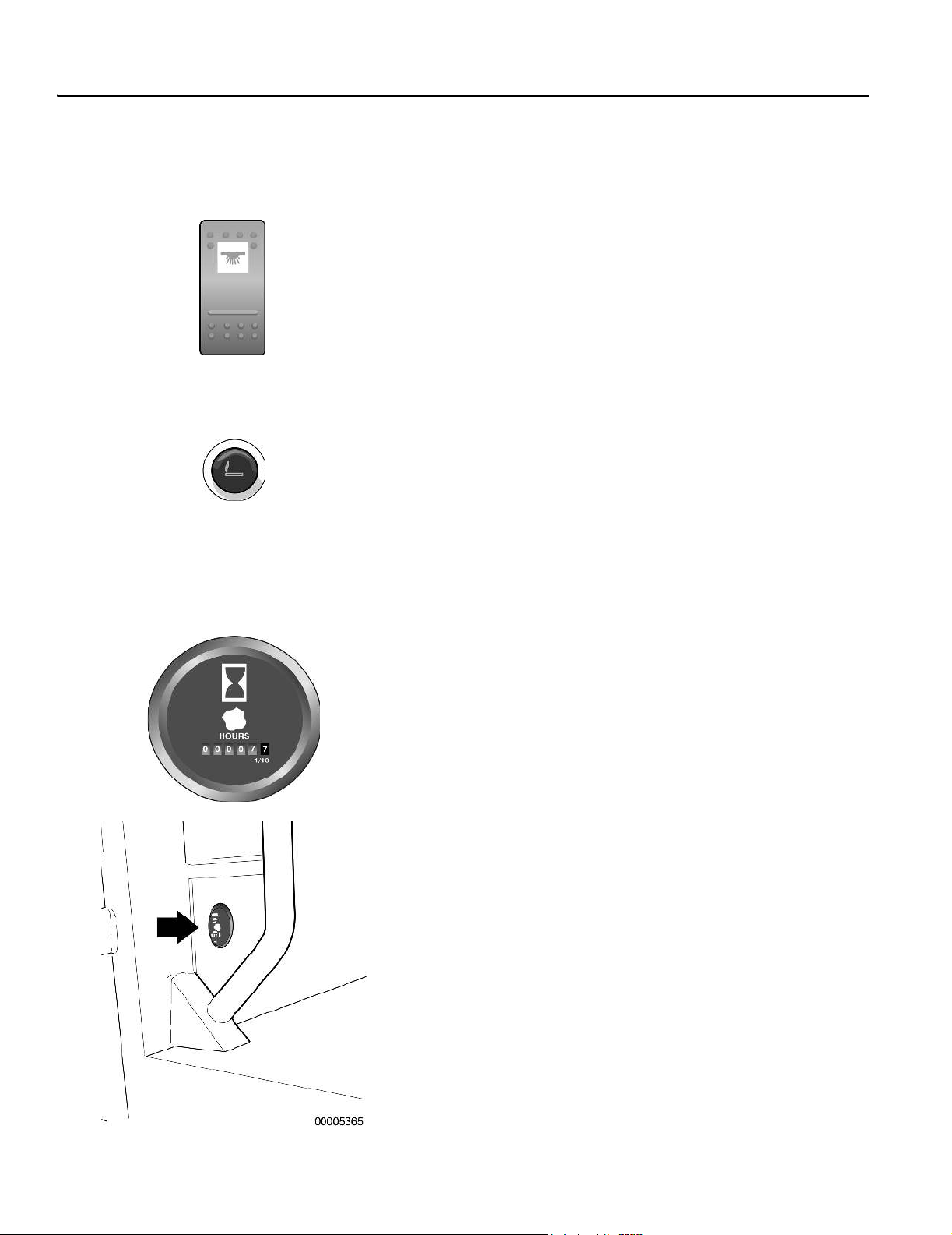
Instrument panels
54 Other
Other
21
Dome light switch
The dome light switch is located on the right-hand door post. Depress the top of the rocker switch to turn on the interior dome light.
Depress the bottom of the switch to turn it off.
22
Cigar lighter
The electric power to the glow coil is connected when the cigar
lighter is pushed in. When the right temperature is reached, the
lighter will be pushed out automatically.
The cigar lighter may also be used as a 12 V DC (15 A) power
socket.
23
Hourmeter
(not shown in main overview illustration)
The Hourmeter is located next to the heater vent on the right-hand
side of the cab. It displays the hours of engine operation.

Operator controls 55
Controls
Operator controls
Controls
1 Clutch pedal 7 Operator seat and seat belt
2 Brake pedal 8 Pedestal tilt pedal
3 Accelerator/decelerator pedal 9 Steering wheel tilt lever
4 Hand throttle lever 10 Climate control system
5 Transmission shift lever 11 Hydraulic controls
6 Steering wheel 12 Auxiliary hydraulic controls (optional)
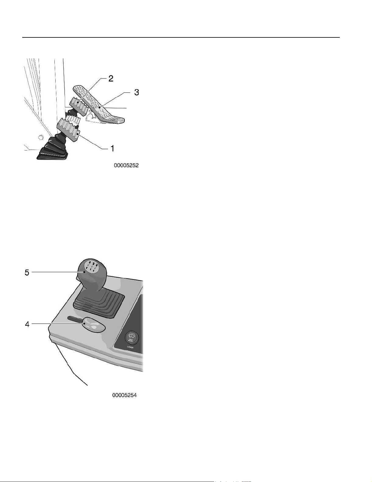
Controls
56 Operator controls
1
Clutch pedal
Use the clutch pedal when you are starting from a complete stop or
changing directions. Do not start to move the grader in any forward
gear higher than 4th or any reverse gear higher than -2nd. Refer to
Shifting gears page 87.
2
Brake pedal
3
Accelerator/decelerator pedal
n Depress the pedal toe to increase rpm.
n Release the pedal to decrease engine rpm.
n Use the pedal to override the hand throttle setting.
n Depress the pedal heel to decrease engine rpm when the hand
throttle is set.
n When you remove your foot from the pedal, the engine speed
will return to the preset hand throttle position. Refer to Hand
throttle.
NOTE! If the engine is started with the hand throttle above low
idle position, the accelerator will not function. Move the hand
throttle lever to low idle position to obtain accelerator response.
4
Hand throttle
The hand throttle provides a fixed engine speed control during grading.
NOTE! Do not use the hand throttle when roading the grader.
The hand throttle is self-locking in any position. Moving the throttle
handle releases the locking mechanism and allows free movement of
the lever. When starting the engine, the hand throttle lever must be in
the low idle position (pulled back towards you) to achieve accelerator
function.
5
Transmission shift lever
The transmission shift lever is mounted in the console on the operator’s right-hand side. The shift lever is equipped with a neutral lock
button. The shift lever may only be moved to the FORWARD or REVERSE position if the neutral lock button on the shift lever knob is
depressed. NEUTRAL may be selected without depressing the neutral lock button. The alarm will sound if the transmission FORWARD
or REVERSE mode is selected when the parking brake is applied.
A digital display is incorporated into the pedestal to show you which
gear the transmission is in. See Transmission gear display page 28.
Refer to Shifting gears page 87.
6
Steering wheel
The steering wheel is used to steer the grader. Refer to Operating
instructions, Steering page 93.
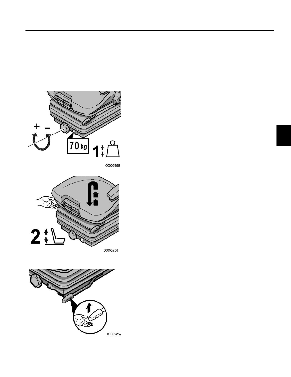
Controls
Operator comfort 57
Operator comfort
7
Operator seat and seat belt
Adjust the seat before starting the grader. Ensure the parking
brake is applied.
Weight adjustment
Adjust the seat for the operator’s weight by turning the weight adjuster knob with the seat empty. The indicator shows the set
weight.
To prevent injury, you must check and adjust the operator’s weight
setting before driving the machine.
Height adjustment
You can adjust the seat height at several settings. Raise the seat
to the required height until it audibly latches into place. When the
seat is raised above the highest setting (endstop), it drops back
down to the lowest position.
Fore/aft adjustment
You can adjust the fore/aft setting by lifting the locking bar or lever
(depending on your model).
The locking bar or lever must latch securely into the desired position. It should not be possible to move the seat into another position when it is locked.

Controls
58 Operator comfort
Seat pan angle adjustment
You can adjust the seat pan angle by lifting the handle on the front
left-hand side of the seat (refer to the illustration).
Exert pressure on or off the seat pan to move it to the desired angle position.
Seat cushion depth adjustment
You can adjust the depth of the seat cushion by lifting the handle
on the front right-hand side of the seat (refer to the illustration).
Move the seat cushion backwards or forwards until you reach the
desired seating position.
Armrest adjustment
You can change the inclination of the armrests by turning the adjustment knob (arrow).

Controls
Operator comfort 59
Armrests
You can fold and adjust the height of the armrests individually if required. To adjust the armrest height, remove the round plastic cap
to expose a hexagon nut (see arrow). Loosen the nut (size 13
mm). Adjust the armrest to the desired position, retighten the nut
and install the round plastic cap.
Lumbar support
You can adjust both the height and curvature of the backrest cushion individually by turning the adjustment knob (arrow) to the left
or right. This helps to increase seating comfort and operator efficiency.
Dirt can impair the function of the seat. Make sure you keep
your seat clean!
Upholstery can be quickly and simply removed from the seat
frame for easy cleaning or replacement. Take care when removing
upholstery from the backrest frame. The frame may jerk forward
and cause injury! When cleaning the upholstery, make sure the
material is not soaked through. Use a standard commercially
available upholstery or plastics cleaning agent. Test first for
compatibility on a small, concealed area.
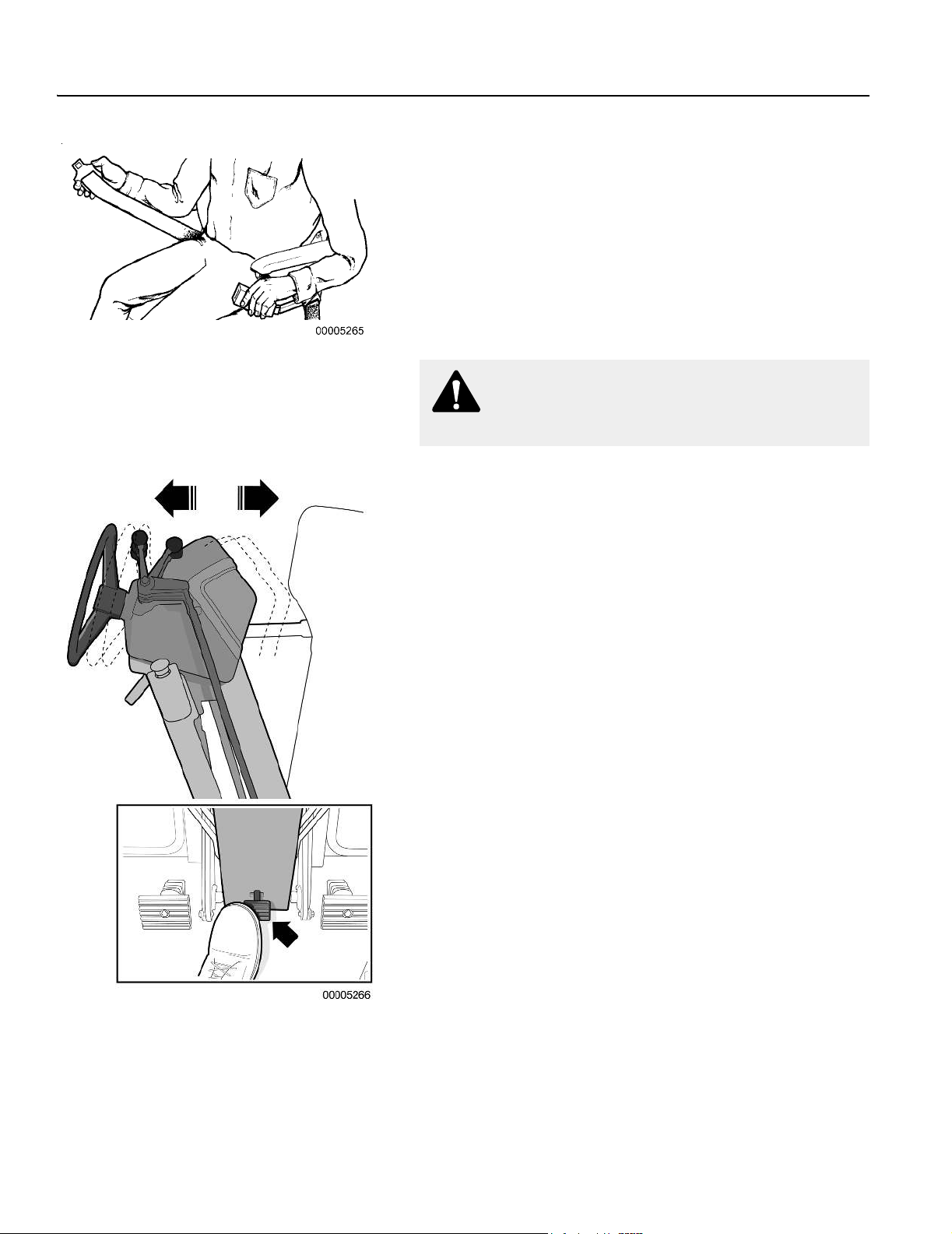
Controls
60 Operator comfort
Seat belt
Adjust the seat and fasten the seat belt. The seat belt must fit snug
and low around your hips. The holding strap must be free of slack.
n Hold the clasp end of the seat belt with your left hand.
n Pull the right side of the belt out from the seat with your right
hand until there is enough slack to reach across your lap to the
clasp.
n Insert the belt into the clasp. Check that it is secure.
n Allow the belt to retract when fastened to fit snug and low
around your hips. The seat belt must be free of slack.
WARNING!
Wear seat belt when operating machine.
8
Pedestal tilt pedal
To move the pedestal forwards or backwards:
n Grasp the steering wheel.
n Push down on the pedal located at the bottom of the pedestal
column.
n Move the pedestal to the desired position and release the
pedal.
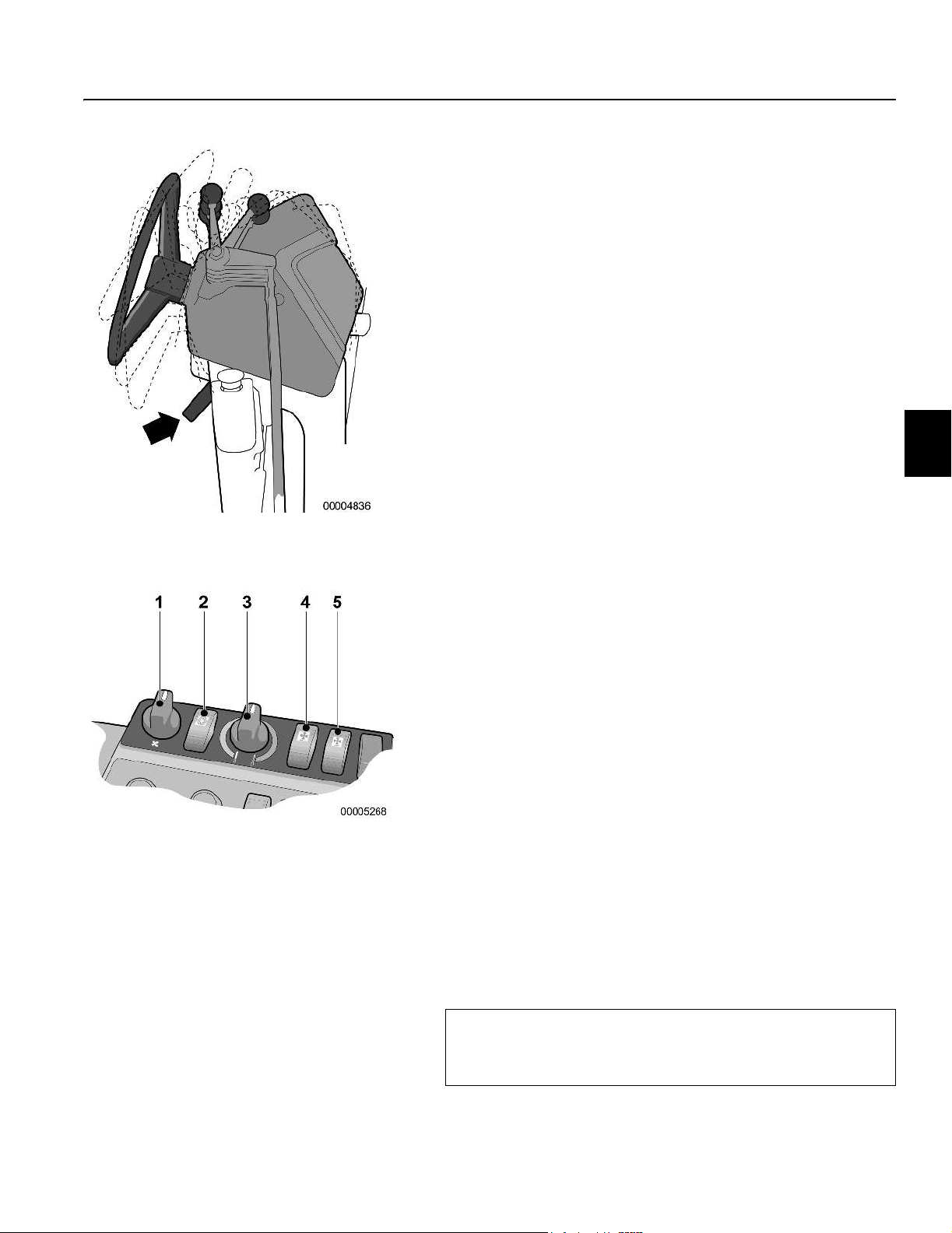
Controls
Operator comfort 61
9
Steering wheel tilt lever
Pull up on this lever to tilt the steering wheel and pedestal head.
Releasing the lever locks the steering wheel in one of the four positions.
To tilt the steering wheel and control head assembly:
n Grasp the steering wheel and lift the lever located on the up-
per right-hand side of the pedestal column.
n Move the steering wheel and control head to one of the four
positions.
n Release the lever and ensure it latches securely.
1 Fan speed switch
2 Air conditioner on/off switch
3 Temperature control switch
4 Front defroster fan switch
5 Rear defroster fan switch
10
Climate control system
Heating, ventilation and air conditioning controls
The controls for the heating, ventilation and air conditioning systems are located on the side console. Filtered, fresh air is supplied
to the cab through upper, mid and lower level vents.
Cab air temperature is controlled using the fan and temperature
controls. Refer to Side console instrument panel page 45. Turn the
switch knobs to increase or decrease the temperature and regulate the fan speed. The air conditioning system is switched on and
off using the rocker switch (2). The defroster fans (4 and 5) are
used to remove condensation and defrost the front and rear windshields.
General information
n Keep doors and windows closed to provide efficient heating
and air conditioning in an enclosed cab.
n Direct air flow away from unprotected skin.
n Adjust the fan speed until the air flow in the cab feels comfo-
ratable.
n For service information on the fresh air filter(s) and recircula-
tion vent/screen, refer to Climate control system page 197.
Provide good ventilation
Do not operate the machine with the doors and windows
closed for extended periods of time without the ventilation
fan running. Lack of fresh air can cause drowsiness.

Controls
62 Operator comfort
Cab air distribution
Upper level vents
These vents are mounted in the upper door posts. The high profile
cab has three louvers, one facing forward and two facing center/
rearward. The low profile cab has two louvers, one facing forward
and one facing center/rearward. All louvers close in the downward
position.
1 Upper vent louvers
2 Rear defroster fan
1 Mid level vents
2 Floor level vents
3 Recirculation vent and screen
Mid level vents
These vents are mounted on the seat floor. Both of these vents
face rearward and close towards the outside of the cab.
If the left-hand side console option is installed, the left-hand louver
is mounted on the inner facing console wall. The louver closes in
the upward position.
Floor level vents
These vents are mounted in the seat riser panel, one per side. The
two louvers for the floor level vents close towards the outside of
the cab.
Recirculation vents and screen
The recirculation vents and screen provide an intake for cab air to
be recirculated through the evaporator and heater cores. The vent
below the seat has a washable foam filter mounted in the inlet
screen.
Air can also be recirculated through the intake tube vents on the
left-hand door post. With the vents closed, more outside air is
drawn into the cab. This position is used for normal winter and
summer operation. With the vents open, intake air is a mix of inside and outside air. This allows more cab air to be recirculated
through the evaporator and cool the cab quicker.
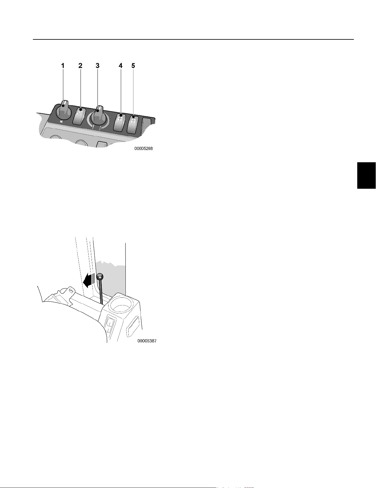
1 Fan speed switch
2 Air conditioner on/off switch
3 Temperature control switch
4 Front defroster fan switch
5 Rear defroster fan switch
Controls
Operator comfort 63
Adjusting heating and ventilation
These instructions are only basic recommendations and each operator should experiment to achieve the best possible working environment in an enclosed cab.
For maximum warmth:
n Ensure heater shut off taps at engine are open
n Open all vent louvers.
n Turn the temperature control switch (3) fully clockwise.
n Turn the fan speed switch (1) to position 3.
n When a comfortable level is reached, turn the temperature
switch (3) until the required temperature is maintained. Turn
the fan speed switch (1) to position 1 or 2.
For a comfortable working temperature:
n Turn the temperature control knob (3) counterclockwise until
a comfortable temperature is reached.
n Reduce the fan speed (1) to 1 or 2.
To defrost or demist the front and rear windshields:
n Turn on the defroster fan switches (4 and 5).
n Adjust the upper front facing louvers and the lower vent lou-
vers towards the side windows.
Cab ventilation
n The cab can also be ventilated by opening the doors. Secure
the doors in the open position by pushing them all the way
open until they latch against the stop on the side of the cab.
n Release the door by pulling the release lever beside the seat.
Adjusting air conditioning
For maximum cooling:
n Turn the fan speed switch (1) to the maximum position.
n Turn on the air conditioning switch (2).
n Turn the temperature control switch counterclockwise to the
minimum position.
n Open the two recirculation vents in the back of the left-hand
door post.
n When the temperature has dropped to the required level, turn
the fan speed switch to 1 or 2. Adjust the temperature control
to a comfortable level.
For a comfortable working temperature:
n Turn the temperature control knob (3) clockwise until a com-
fortable temperature is reached.
n Reduce the fan speed (1) to 1 or 2.

Controls
64 Hydraulic controls
Hydraulic controls
1 Left-hand blade lift lever 6 Right-hand blade lift lever
2 Moldboard slide shift lever 7 Control lever for scarifier, ripper or windrow eliminator
3 Circle turn lever 8 Articulation lever
4 Circle shift lever 9 Moldboard tilt lever
5 Front wheel lean lever 10 A-frame attachments lever
11
Hydraulic controls
1 and 6
Left-hand and right-hand blade lift
n Push forward on both levers at the same time to lower the
moldboard.
n Pull back on both levers at the same time to raise the mold-
board.

Controls
Hydraulic controls 65
n Push forward on the lever for the side you wish to lower.
n Pull back on the lever for the side you wish to raise.
Electric float valves
n On graders equipped with optional blade float, push forward
on the lever until it locks in the detent (see figure). Pull backward on the lever to return it to the normal operating position.
WARNING!
Do not use the float control to lower the moldboard. Loss
of control of the grader could result.
1 Float detent position
1 Float valves power switch
2 Front float valve system indicator lamps
Front float valve system operation
Graders equipped with float valves allow the moldboard and/or Aframe attachment to ‘float’ along the ground by following the surface contours. For snow wing float, refer to Hydraulic snow wing
page 121.
Either or both blade lift cylinders can be put into float to allow independent control of each end of the moldboard.
Use moldboard float to remove snow, move loose material on
hard-packed surfaces or to level loose material to a hard surface.
(Float only the moldboard end contacting the hard surface.)
n The float valves power switch is located on the right-hand side
of the pedestal.
n Ensure the levers are in the non-float detent position.
n Push the power switch up to activate the system. This is a mo-
mentary style switch. Indicator lamps mounted on the front
right-hand side of the pedestal indicate that the system is activated.
n The ignition key must be in the “I” position to activate the sys-
tem using the float valves power switch.
n Push the float valves power switch down to de-activate the
system. The system also de-activates when you turn the ignition key to the OFF position.

Controls
66 Hydraulic controls
2
Moldboard slide shift lever
This lever is the third lever in from the extreme left. It controls the
left-to-right sliding action of the moldboard.
n Push forward on the moldboard slide shift lever to slide the
blade out to the left-hand side of the grader.
n Pull back on the lever to slide the blade to the right-hand side
of the grader.
3
Circle turn lever
This lever is the fifth lever in from the extreme left. It controls the
clockwise and counterclockwise rotation of the circle and moldboard assembly.
n Push forward on the circle turn lever to rotate the circle coun-
terclockwise.
n Pull back on the lever to rotate the circle clockwise.
WARNING!
Keep clear when engine is running or moldboard is off
ground.
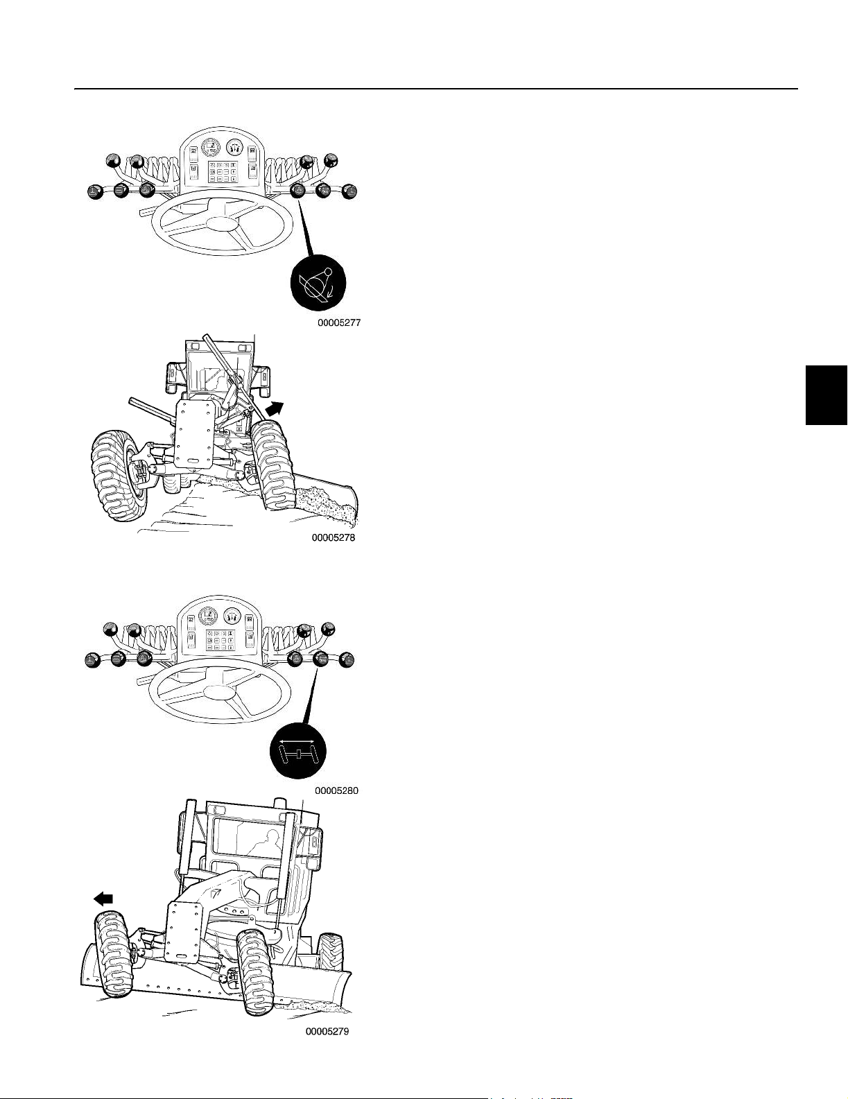
Controls
Hydraulic controls 67
4
Circle shift lever
This lever is the fifth lever in from the extreme right. It controls the
circle shift function.
n Push forward on the circle shift lever to move the circle and
moldboard assembly to the left.
n Pull back on the lever to move the assembly to the right.
5
Front wheel lean lever
This lever is the third lever in from the extreme right. It controls the
lean of the front wheels to the left or right for a reduced turning radius and improved machine stability while grading.
n Push forward on the wheel lean lever to lean the front wheels
to the left.
n Pull back on the lever to lean the wheels to the right.

Controls
68 Hydraulic controls
7
Control lever for scarifier, ripper or windrow elimi-
nator
This lever is the second lever in from the extreme right. The attachments lever normally controls the scarifier function. The lever
also controls either a ripper or windrow eliminator if the grader is
not equipped with a scarifier.
n Push forward on the control lever to lower the attachment.
n Pull back on the lever to raise the attachment.
8
Articulation lever
This lever is located fourth from the extreme right. The articulation
lever controls the direction of the articulation function.
NOTE! Remove the articulation lock pins before attempting to
articulate the grader.
n Push forward on the control lever to articulate the grader to the
left.
n Pull back on the lever to articulate the grader to the right.
n The indicator gauge in the pedestal displays the amount of
frame articulation.
Refer to Steering using articulation page 93.
WARNING!
Do not articulate the grader when operating on steep
slopes or when roading the machine. Grader could roll
over. Severe personal injury or death could result. Always
articulate the grader prior to moving onto the slope.
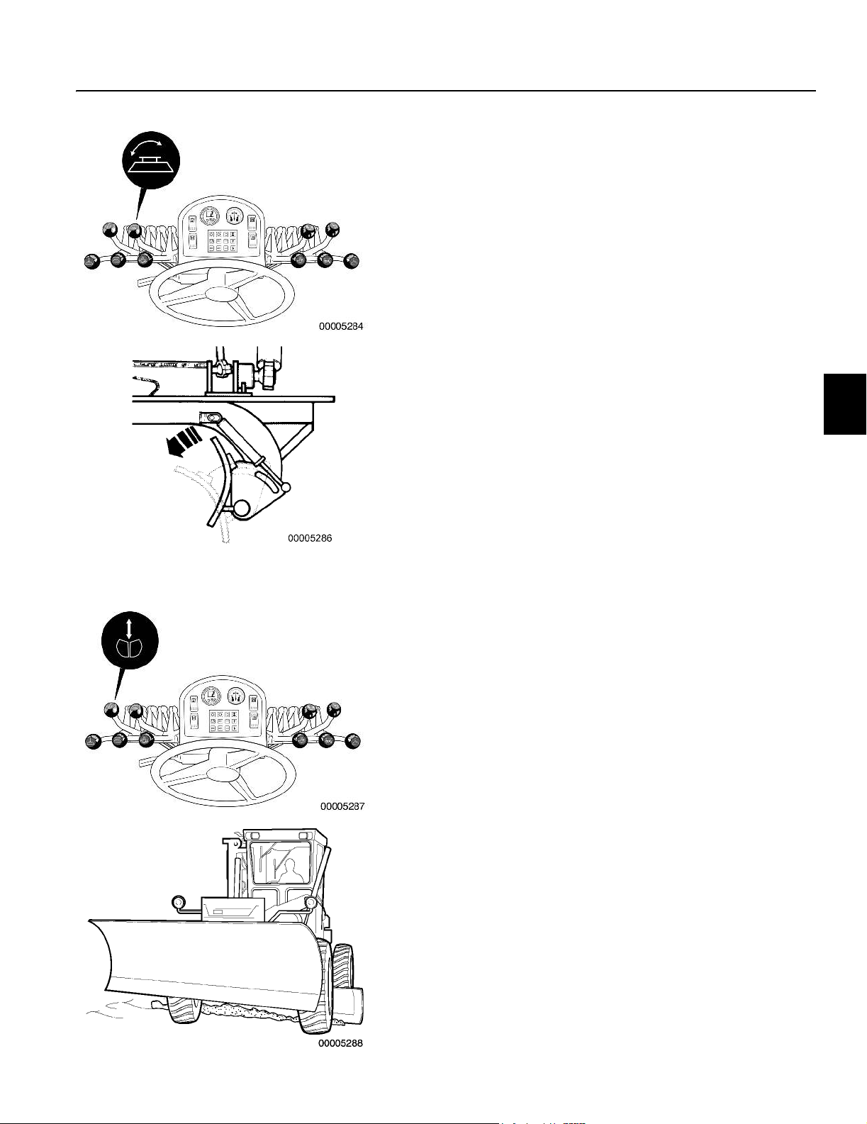
Controls
Hydraulic controls 69
9
Moldboard tilt lever
This lever is located fourth from the extreme left. Use the moldboard tilt feature to ensure that the grading material rolls freely off
the blade.
n Push forward on this lever to tilt the moldboard forward.
n Pull back on this lever to tilt the moldboard rearward.
10
A-frame attachments lever
This lever is the second lever in from the extreme left. It controls
the raising and lowering action of the front-mounted dozer blade/
scarifier or other attachment.
n Push the lever forward to lower the attachment.
n Pull the lever back to raise the attachment.
On motor graders equipped with optional front lift float capabilities,
operate the lever to select the detent position. Refer to Front float
valve system operation page 65 for further information.
n For float action, push forward on the lever until it locks in the
detent.
n Pull backward on the lever to return it to the normal operating
position.

Controls
70 Hydraulic controls
12
Auxiliary hydraulic controls
(optional)
Controls levers for additional attachments such as a rear ripper,
windrow eliminator or snow wing as equipped are placed to the
right of the operator’s seat.
n Push forward on the control lever to lower the attachment.
n Pull back on the lever to raise the attachment.
For further information on attachments, see Operating instructions
Scarifier page 115, Ripper page 116, Windrow eliminator page
117, Dozer blade/V-plow page 119, One way plow page 120, and
Hydraulic snow wing page 121.
1 Extra hydraulic circuits
2 Snow wing front mast
3 Snow wing rear mast slide/ripper/windrow elimi-
nator
4 Extra hydraulic circuits
5 Snow wing lift

Controls
Other controls 71
Other controls
(not shown in main overview illustration)
Accumulators
Some graders are equipped with blade lift and circle shift accumulators. The accumulators absorb shock loads and protect the system from impact damage when the grader is working in severe
applications.
In fine grading operations where a high degree of blading tolerance is needed, the accumulators can be isolated from the hydraulic system. This is done using shut-off valves. Shut-off valve
handles are found in the toolbox located on the right-hand tandem
case for this purpose. Turn the handle clockwise to disconnect the
accumulator from the hydraulic system.
Turn the handle counterclockwise to connect the accumulator to
the hydraulic system.
Radio/tape player
A factory-installed radio/tape player is available as an option. The
radio console is mounted in the headliner to the left behind the operator. Twin speakers are installed in the upper rear corners of the
cab. Refer to the instructions supplied in the package of manuals.
Battery isolation switch
The battery isolation switch is located inside the engine compartment on the left-hand side of the grader. The switch cuts off electricity between the batteries and the grader’s electrical system.
n Turn the switch OFF to the (O) position and all electrical de-
vices are inoperative.
n Turn the switch ON to the (I) position to reconnect the electri-
cal system.
NOTE! Do not bypass the battery isolation switch. Have the
switch repaired if it is not working properly.

Notes

Operating instructions
Introduction 73
Operating instructions
Introduction
This chapter contains rules which must be followed to make working with the machine safe. However, these rules do not relieve the
operator from following laws or other national regulations for traffic
safety, industrial safety, and labor welfare.
Alertness, judgement and respect for applicable safety regulations
are conditions necessary to avoid the risk of accidents.

Operating instructions
74 Running-in period
Running-in period
NOTE! Check oil pressure and temperature often.
During the running-in period or the first 50 hours, the machine
must be operated with a certain amount of care.
The following instructions and intervals apply during the runningin period.
Engine
The engine oil should be changed and the filters replaced after
100 hours of operation. Other new engine commissioning operations to be performed at this time are:
– Replace fuel filter cartridge
– Drain and check fuel filter/water separator.
– Check engine mounts (retighten as necessary)
– Check V-belts (retighten as necessary)
– Inspect engine for leaks
Filters
Change the following filters after the initial 100 hours. Refer to
Recommended lubricants page 217
– Change the hydraulic oil filter after the first 100 hours, then ev-
ery 500 hours thereafter. See Hydraulic system filter element
page 194.
– Change the transmission filter after the first 100 hours, then
every 500 hours thereafter. See Transmission filter element
page 186.
for further instructions.
Lubricants
Change the following lubricants after the initial 100 hours.
– Change the final drive lubricant and clean the magnetic plug,
see Final drives page 188.
– Change the All Wheel Drive gearbox oil (if equipped), refer to
All Wheel Drive, Gearbox oil, changing page 195.
Other checks
Re-torque the final drive to frame bolts and the final drive to tandem bolts. See Critical mounting torques page 231.

Hand signals for on-site traffic control
1Back-up
2 Clearance
3Stop
4 Change direction
Operating instructions
Safety and responsibility 75
Safety and responsibility
Operator duties
The operator should know and pay attention to the specific requirements and risks at the worksite and when travelling on public
roads. The operator should therefore read the rules stated below
to learn how to avoid serious personal injuries and property damage.
Operator precautions
n Avoid loose fitting clothing, loose or uncovered long hair, jew-
elry and loose personal articles. These can be caught in moving parts. Jewelry may also ground a live electrical circuit.
n Know and use the protective equipment that is to be worn
when operating or servicing the grader. Hard hats, protective
glasses, protective shoes, gloves, reflector type vests, respirators and hearing protection are types of equipment that may
be required.
n Do not rush. Walk, do not run.
n Keep the steps, handholds, operator’s platform, seat, pedals
and controls in good condition. Keep them clean and clear of
debris, mud, ice and grease.
n Do not dismount from the grader with the engine running. Be-
fore leaving the operator’s cab, place the transmission in neutral, lower the moldboard and all attachments to the ground.
Apply the parking brake. Shut down the engine. Remove and
retain the ignition key.
n Know and use the hand signals required for particular jobs.
Know who has the responsibility for signaling. Ensure the
lights are working properly at all times.
n Clean the grader regularly. Keep windows, mirrors and lights
clean. Replace all broken windows and mirrors.
n Ensure the back-up alarm and back-up lights work properly.
Never disconnect the back-up alarm or lights.
n Ensure that your grader is properly equipped for emergencies.
Equipment such as a fire extinguisher, first aid kit, flares may
be required. Locate and know how to use this equipment.
n It is the responsibility of the machine user to determine the ex-
istence of special hazards such as toxic gases, ground conditions, etc. that require special precautions. Take the
necessary actions to eliminate the hazards.
WARNING!
Do not coast downhill. Excess speed could cause serious
transmission damage and loss of control of grader.
Severe personal injury or death could result.
n Select a gear that will prevent excessive speed when going
downhill.
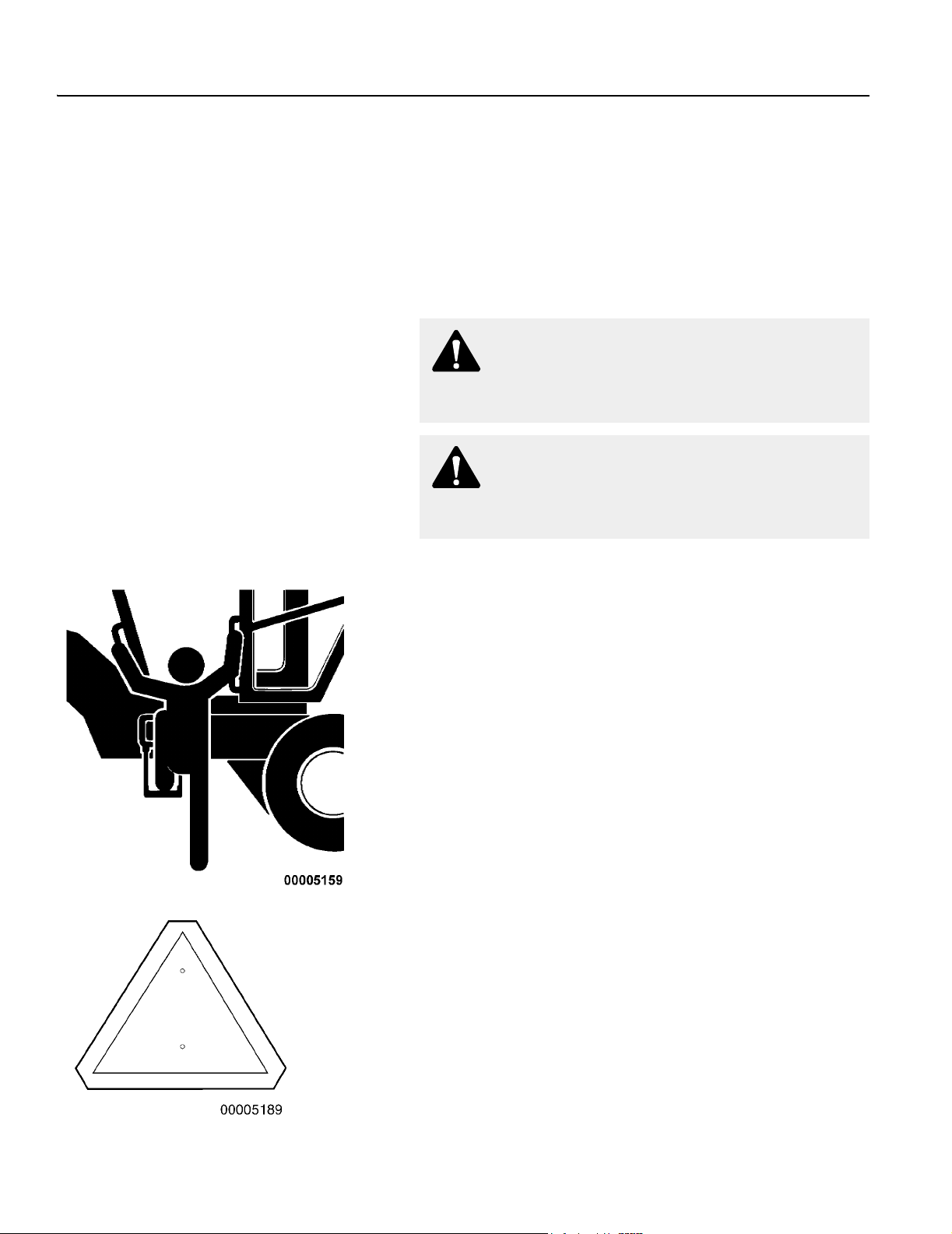
Operating instructions
76 Safety and responsibility
n When operating close to electrical lines, underground cables,
n Know and understand the job site traffic flow patterns and
n Watch for bystanders and never allow anyone to be under or
water mains or gas lines, contact the responsible authority
and request assistance. Contact with a buried pipeline or cable could result in serious injury or death due to fire or explosion.
obey flagmen, road signs and signals. Signal before turning.
to reach into the grader and its attachments while operating.
WARNING!
Sudden loss of any fluid indicates a serious malfunction.
Stop grader and consult a qualified service technician.
WARNING!
Do not use float control to lower moldboard. Loss of
control of grader could result.
SMV Plate (slow moving vehicle)
Mounting and dismounting
n Face the cab when climbing in or out of the grader. Use the
handholds and steps provided. Maintain three points of support. For example, two hands and one foot or one hand and
two feet.
n Do not mount or operate the grader with wet or greasy hands,
muddy shoes or boots.
n Do not jump from the grader at any time.
n Never try to mount or dismount the grader while it is moving.
Know and use the hand signals required for particular jobs.
Know who has the responsibility for signaling.
Driving on a roadway
n Understand and obey traffic laws, road signs and signals.
n Keep both ends of the moldboard high and within the width of
the grader.
n Use extra caution at all intersections.
n Be aware of traffic behind you. If necessary, pull over to the
side of the road and allow the vehicles to pass safely.
n Stop and look both ways at railway crossings. Proceed when
clear.
n Ensure your grader is properly equipped for roading. Such
equipment as lights, flashing beacon, turn signals and warning devices such as flags and a slow moving vehicle sign may
be required. Check the local traffic laws for the correct traveling requirements.
n Ensure the articulation lock pins are installed when roading
the grader.
n Drive cautiously when entering or leaving the shoulder of the
road to avoid a rollover.
n Do not use the hand throttle when roading the grader.

Operating instructions
Safety and responsibility 77
Job site precautions
n Know and understand the job site traffic flow patterns and
obey flagmen, road signs and signals.
n When moving the grader backwards, have a flagman direct
you and the traffic around you. If a flagman is not available,
look around and behind the grader to ensure the area is clear
before moving.
n When scarifying or ripping across a slope, keep the mold-
board parallel with the front axle, centered to the frame and
lowered close to the ground to provide protection against rolling over.
n Do not dismount from the grader with the engine running. Be-
fore leaving the operator’s cab, place the transmission in
NEUTRAL, lower the moldboard and all the attachments to
the ground. Apply the parking brake. Shut down the engine.
Remove and retain the ignition key.
n Use the clutch pedal when starting, stopping, or when chang-
ing direction.
WARNING!
Do not articulate the grader when operating on steep
slopes. Grader could roll over. Severe personal injury or
death could result.
Night operation
n Ensure the grader is properly equipped for night operation.
Equipment such as worklights, headlights, beacons and a
slow moving vehicle sign may be required.
n Ensure the worklights are properly aimed. Dim the headlights
for approaching traffic.
n When stopping at night near traffic areas, drive the grader off
to the side of the road and set out flares or reflectors.
Snow removal
n Snow removal presents unique hazards due to weather con-
ditions, poor visibility, slippery road surfaces, high operating
speed, and other traffic. Be sure your grader is in good condition and that you have been properly trained before doing this
work.
n Ensure your grader has the proper attachments before plow-
ing snow. Equipment such as tire chains, warning lights, additional beacons and markings may be required.
n Keep your windshield and other window areas clean and clear
for the best possible visibility. Use the windshield wipers and
the window defrosters.
n Be alert for any obstructions covered by snow. Obstructions
such as manhole covers, curbs, bridge abutments, embankments and fire hydrants, etc. may be hazardous.
n Ensure the snow wing is fully raised when not in use and se-
cured with the proper chains.
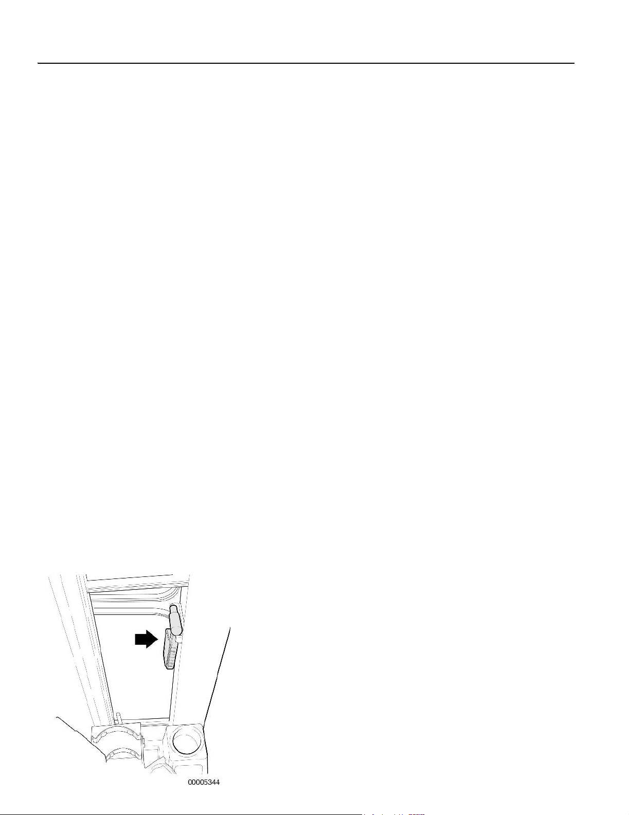
Operating instructions
78 Safety and responsibility
Special hazards
n Do not stop or turn the grader around on curves or at the crest
n Be alert when grading haul roads as normal rules of the road
n Use extra care when grading against oncoming traffic. Pre-
n Do not operate the grader in areas where volatile gases may
Fire
n Remove dust and combustible debris from the grader regular-
n Inspect the grader daily for potential fire hazards such as
n Ensure that excess oil, grease or fuel is cleaned up immedi-
n Ensure the grader is properly equipped for grading in dry or
of hills.
might not be observed.
cautions such as flags, barricades, flashing lights, and flagmen may be needed to alert traffic.
be present. Explosion could result. If you encounter an area
where volatile gases may be present, shut down the grader
and leave the area immediately.
ly.
damaged electrical wires. Have necessary repairs made immediately.
ately.
forested areas. Equipment such as a spark arrestor may be
required.
When there is a risk of overturning
ROPS
The cab is for the protection of the operator and meets the requirements for Roll Over Protective Structure according to the adopted
standard (ROPS). A precondition for the protection is that the operator uses the seat belt and remains in the cab. Therefore, hold
on to the steering wheel if the machine should roll over. Do not
jump!
FOPS
The cab is designed to meet the requirements for objects falling
onto the cab roof according to given testing methods for Falling
Object Protective Structure (FOPS). A precondition for the protection is that the operator uses the seat belt and remains in the cab.
Therefore, hold to the steering wheel if the machine should roll
over. Do not jump!
Emergency exit
The left-hand door opening is the most commonly used entrance.
The right-hand door opening can be used as the EXIT in case of
an emergency.
Models equipped with a snow wing are supplied with an emergency hammer located inside the left-hand door post. It can be used
to break the glass in case of a rollover.

Operating instructions
Safety and responsibility 79
Towing
n When it is necessary to tow the grader, do not exceed 8 km/h
(5 mph).
n Be sure the towing machine has sufficient braking capacity to
stop the towed load.
n If the towed grader cannot be braked, a tow bar or two towing
machines must be used – one in front pulling and one at the
rear to provide braking. Do not tow over long distances.
n Use the tow hitch when using the grader for towing. If a cable
or chain is used, keep people away from the towline.
n Shielding of the operator(s) against towline breakage must be
provided. Refer to Operating instructions, To wing page 101.
WARNING!
Improper towing methods or equipment could result in
severe personal injury or death. Read and understand the
towing instructions and precautions in this manual.
Transporting
n Exercise safety and follow all local laws when loading, unload-
ing or transporting the grader. Refer to Operating instructions,
Safety and responsibility, Transporting the machine page 103.

Operating instructions
80 Before operating
Before operating
General rules
n Do not operate the grader unless you are a qualified operator.
n Read and understand the entire Operator’s Manual. Before
you operate the grader, understand its performance characteristics, capabilities and limitations, and become thoroughly
familiar with all controls and instruments.
n Consult your supervisor if you do not understand the Opera-
tor’s Manual.
n Read and obey all safety signs on the grader. Ensure they are
kept clean and in good condition. Replace the safety signs if
they are damaged, missing or illegible. Refer to Plates and de-
cals page 12.
n Never drive or operate the grader while you are under the in-
fluence of alcohol or drugs.
n Know and follow your safety program rules.
n For specific safety requirements, potential work area hazards
and the necessary precautions, consult your supervisor.
n Before operating the grader, ensure it is properly equipped.
Consult your supervisor or your Volvo Dealer for details.
n Do not permit riders in or on the grader. Ensure all doors, pan-
els, inspection covers and the battery box cover are in place
and secure.
n Remove or secure loose objects in the cab such as lunch box-
es, tools, etc. Remove all objects which do not belong in or on
the grader.
n Before backing up, use extra care to ensure all persons and
vehicles are clear of the grader.
n Adjust the seat and fasten the seat belt. The seat belt must fit
snug and low around your hips. The holding strap must be free
of slack.
n Ensure the snow wing is fully raised when not in use and se-
cured with the proper chains.
n Before operating your grader, test the brakes, steering, trans-
mission, clutch and all controls and functions. Perform the test
in an area where the safety of personnel and property will not
be in jeopardy.
n If a malfunction is observed, park the grader and place a ‘DO
NOT OPERATE’ or similar warning tag on the steering wheel
and/or battery isolation switch. Be sure to remove the ignition
key. Report the problem and have it repaired before operating
the grader.
n If a failure occurs that causes loss of control such as steering,
service brakes or engine, stop the grader as quickly as possible. Keep the grader securely parked until the malfunction is
corrected or the grader can be safely towed.
n Understand the grader’s limitations and keep the grader under
control.
n Drive the grader with care and at speeds compatible with con-
ditions. Use extra caution when operating over rough ground,
on slopes, when ditching and when turning the grader.

Operating instructions
Before operating 81
n Know your stopping distance at any speed. Regulate the
speed of your grader accordingly.
n Note and avoid all hazards and obstructions such as over-
hangs, ledges, slide areas, electrical lines, underground cables, water mains, gas lines, etc.
Daily pre-start checks
Before making any checks, ensure the grader is in the Service position. Refer to Service position page 146.
Carry out daily maintenance, see Service and maintenance, Daily
(every 10 hours) page 205.
Conduct a daily inspection of your grader every 4 to 24 hours of
operation or at the beginning of each work shift.
Perform the following general walk-around inspection before
climbing into the cab. Report any faults.
1 Look for oil and coolant leaks. Report all tire damage, pinched
hoses, loose bolts or worn cutting edges. Have them repaired or
replaced.
2 Clear away any debris from the moldboard or circle turn area.
3 Check that the moldboard slide rails and circle top surface are
clean.
4 Ensure the safety signs are clean and in good condition. Re-
place them if damaged, missing or illegible.
5 Check for ‘DO NOT OPERATE’ or similar warning tags.
6 Clean the cab glass.
7 Check adjustment of all rearview mirrors.
8 Before starting the grader, remove all tools and other loose ob-
jects from the machine.
9 Ensure the lights, back-up alarm and other warning and safety
devices are clean and working properly.
10 Warn all personnel who may be servicing the grader or are in its
path prior to starting. Do not start the engine until all personnel
are clearly away from the grader.
11 Secondary steering system check. If your grader has this option
installed, perform this check once a week or every 50 hours before you start the engine. Refer to Secondary steering system
test switch page 42.

Operating instructions
82 Before operating
Procedures before starting the machine
Before starting the grader, check for ‘DO NOT OPERATE’ or sim-
ilar warning tags. Turn the battery isolation switch on.
n Perform the ‘Pre-start checks’ in this manual before starting
the grader.
n Start and operate the grader only from the operator’s seat.
n Adjust the seat and fasten the seat belt. The seat belt must fit
snug and low around your hips. The holding strap must be free
of slack.
n Know how to shut the engine down before attempting to start
it.
n Check the transmission shift lever to ensure it is in NEUTRAL
before starting the engine.
n Ensure the parking brake is applied.
n Sound the horn before starting the engine.
n Do not operate the engine in an enclosed area without ade-
quate ventilation.
n Do not bypass the battery isolation switch. Have the switch re-
paired if it is not working properly.
n Use jumper cables only in the recommended manner. Improp-
er use can result in battery explosion or unexpected movement of the grader. Refer to Starting with jumper cables: page
182.
n After the engine has started, check all gauges and indicators
for proper readings. Shut down the engine immediately if any
improper readings or energized warning lamps are observed.
Refer to Instrument panels page 21.
n Ensure that the lights work properly.
n Check that the hydraulic controls function properly.
n Check that the parking and service brakes function properly.
Refer to Braking page 95.
n Check that the engine hand throttle and accelerator function
properly.
n Listen for unusual noises.
n Look around and behind the grader before moving it.
n Check that the left-hand steering and right-hand steering func-
tion properly.
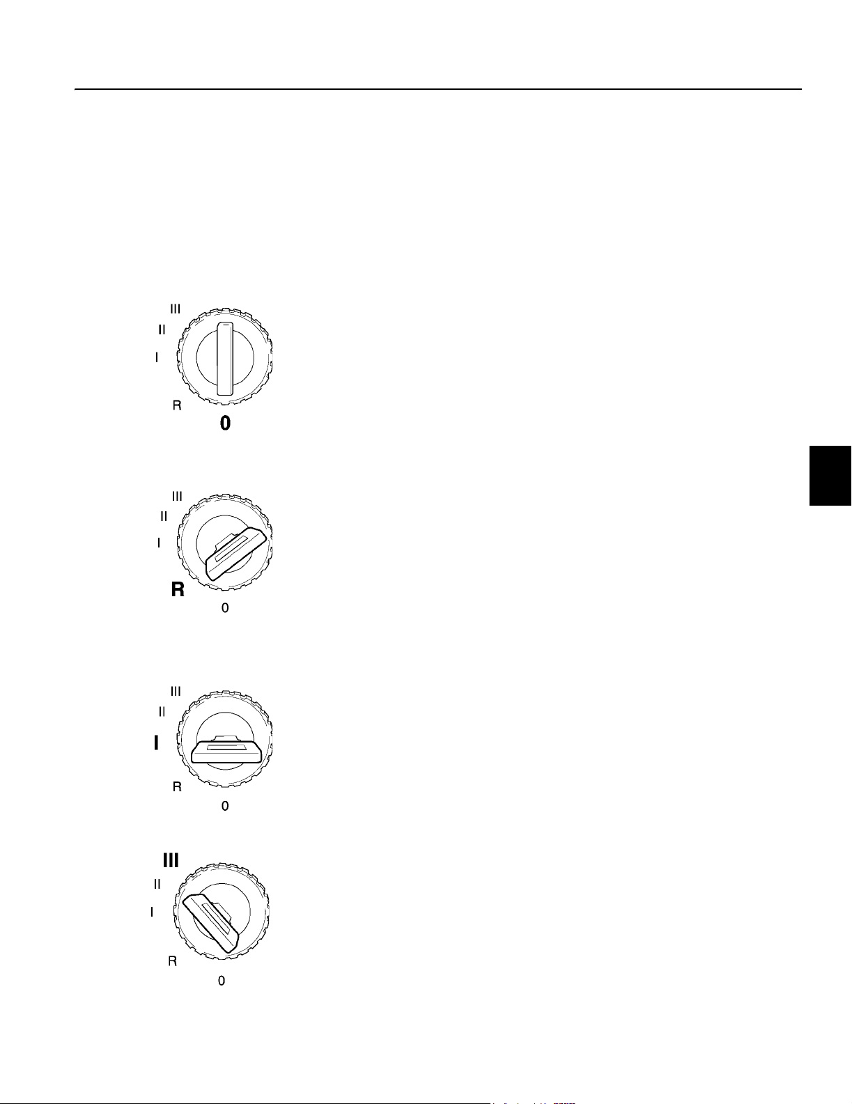
Operating instructions
Ignition switch 83
Ignition switch
The ignition switch has four positions:
NOTE! Position II is not used.
O Turned off
R Radio position
I Running position and preheating position
III Starting position
O (OFF position)
In the “O” position, the engine stops immediately and the electrical
system is turned off.
NOTE! With the parking brake released and the ignition key in
the I position, the brake will be automatically applied if the
switch is moved to the R or O positions.
R (Radio position)
When the ignition key is in the “R” position:
– Current is supplied to some electrical equipment
– The engine is off in this position
NOTE! With the parking brake released and the ignition key in
the I position, the brake will be automatically applied if the
switch is moved to the R or O positions.
I (Running position and preheat position)
In the “I” position:
– The electrical system is turned on
– Engine preheating can be engaged
– The engines runs in this position
III (Start position)
The starter will be engaged with the ignition key in the “III” position.

Operating instructions
84 Ignition switch
Checking instruments and control lamps
Turn the ignition key to the “I” position (running position). The following control lamps should illuminate.
Red lamps
Red central warning
Battery charge warning
Hydraulic oil temperature warning
Transmission pressure warning
Service brake warning
Parking brake applied
Primary steering system warning
Hydraulic oil level warning
Hydraulic oil pressure warning
Amber lamps
Central warning
Differential lock engaged
MBCS lock disengaged
Engine air filter restriction
Hydraulic filter bypass
Secondary steering system
Engine preheat status
Green lamps
Turn signal indicator lights
Blue lamps
High beam lights
If any of these lamps do not light up, either the lamp is faulty or
there is a fault in the electrical system. Have this problem corrected before start-up. All lamps should be extinguished when the
grader starts up (unless there is a message in the display panel
stating otherwise).
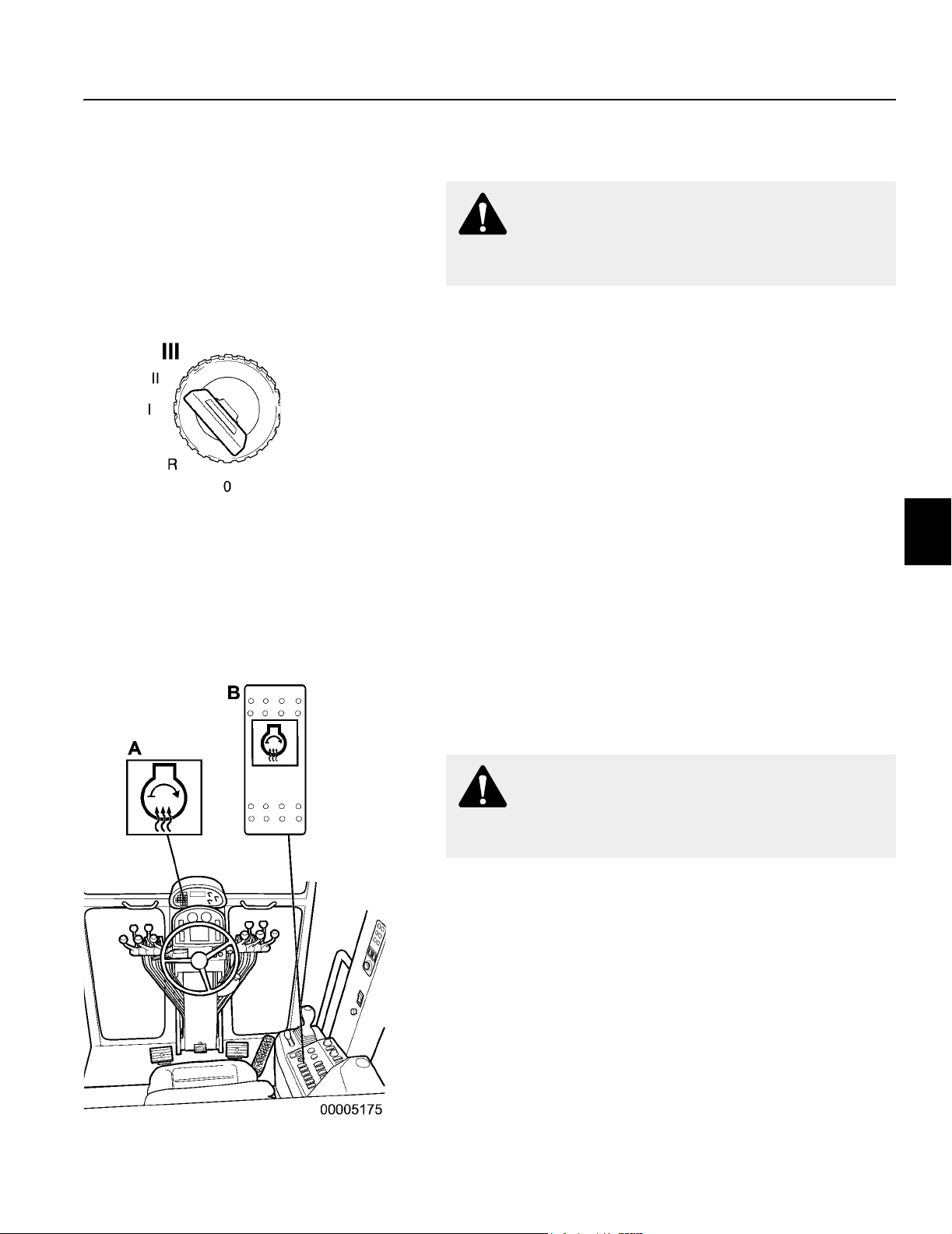
Operating instructions
Starting the engine 85
Starting the engine
WARNING!
Keep clear of the articulation joint when the engine is
running. There is a risk of crushing.
IMPORTANT! After starting the engine, run it at low idle
speed for at least 30 seconds. This is to ensure proper lubrication pressure.
IMPORTANT! Do not hold the key in the starting (III) position
for more than 20 seconds. This could seriously damage the
starting system. Wait 2 minutes, then try to start the engine
again.
1 Push in the parking brake switch to apply parking brake.
2 Place the transmission shifter in neutral.
3 Place the hand throttle lever in the low idle position.
4 Insert the ignition key in the switch and rotate the key clockwise
to position “III” (start position).
5 Release the key when engine starts.
If the engine does not start:
6 Wait until the engine has stopped completely. 7 Turn the key back to the “O” position before a new starting at-
tempt is made.
A Control lamp, preheating element
B Switch, preheating element
Starting a cold engine
Engine preheating should be used when the engine temperature is below 0° C (32° F).
WARNING!
Do not use starting aids (ether, etc.) when preheating the
engine. Serious engine damage could result.
1 Turn the ignition key to position “I” (Running position and preheat
position).
2 Momentarily depress the Preheat element switch beside the igni-
tion switch on the side console. The preheat now remains engaged
for up to 50 seconds and the control lamp will illuminate.
3 When the control lamp goes out, turn the ignition key clockwise to
position “III” (start position). Release the key when the engine
starts. Making a starting attempt during the preheat cycle will cancel the preheat.
NOTE! The use of an immersion heater to warm the oil in the
engine is highly recommended or, if possible, store the grader inside a heated facility.
4 After starting, the lamp may come on for a short period of time
indicating post heat.
NOTE! If the control lamp stays on after a 50 second period,
the preheating element is still connected. Check the function
of the element as there is a risk of overheating.

Operating instructions
86 Starting the engine
Cold weather operation
During the cold season or at temperatures below 0°C (32°F)
note the following points:
– Make sure the freezing point of the coolant corresponds to the
weather conditions, according to Coolant with anti-freeze and
corrosion protection page 174.
– Use recommended lubricating oil for winter use. See Recom-
mended lubricants page 217.
– Fill the fuel tank after work has finished for the day. This will
counteract condensation water in the fuel tank.
– When the engine has started, run it at low speed and light
loading until the oil in the engine, transmission, hydraulic system and final drive have warmed up and become more fluid to
provide proper lubrication.
NOTE! When it is very cold (below – 15°C = 5°F) the machine
must not be put to hard work immediately after the engine is
started. Allow the engine to run just above idle at 1000 to 1100
rpm with the transmission in neutral for 10 to 15 minutes.
NOTE! To start with booster cables, see Starting with jumper
cables: page 182.
Lubricant requirements for transmission and hydraulic systems
When operating in temperatures below –10° C (14° F), store the
grader inside a heated facility or use immersion heaters in the
transmission case and the hydraulic tank. You can use the recommended oils provided the following conditions are met (refer to
Recommended lubricants page 217):
a) Before start up, the oil is preheated to a temperature above
the minimum value for the indicated oil and viscosity range.
b) The operating temperature stays above the minimum value in
the applicable range.
Failure to comply with these requirements may result in a malfunction or reduced life of the transmission or hydraulic components.
Cold weather start-up – Hydraulic system
If oil in the hydraulic circuit is cold, hydraulic functions may move
slowly. Do not attempt grader operations until the hydraulic oil is
warmed up. If you do not follow the proper warm up procedure, hydraulic pump damage may result.
a) Run the engine at approximately 1000 rpm for five minutes.
Do not put load on the hydraulic system.
b) Cycle all hydraulic cylinders through their working range several times until the hydraulic functions operate normally.

1 Clutch pedal
2 Brake pedal
3 Accelerator/decelerator pedal
Operating instructions
Shifting gears 87
Shifting gears
Use the clutch pedal when you are starting from a complete stop
or changing directions.
NOTE! Do not start to move the grader in any forward gear
higher than 4th or any reverse gear higher than -2nd.
Starting out
n Raise the moldboard and all attachments off the ground. Re-
fer to Hydraulic controls page 64.
n If roading the grader, position the moldboard inside the tires.
Steer the front wheels to make sure they do not strike the
moldboard.
n Depress the clutch and brake pedals.
n Pull out the parking brake switch to release the parking brake.
n Depress the neutral lock button and move the shift lever into
the FORWARD or REVERSE position.
n Select the starting gear by nudging the shift lever to the right
or to the left. A digital display is incorporated into the pedestal
to tell you which gear the transmission is in.
n Release the brake pedal, then slowly release the clutch pedal
and accelerate as required.
NOTE! Do not rest your feet on the clutch or brake pedals
when driving the grader. This can cause unnecessary wear
and premature failure.
AForward
B Reverse
C Neutral lock button

Operating instructions
88 Shifting gears
Changing gears
Once the grader is in motion, you do not have to use the clutch
pedal to change gears.
n To shift to a higher gear, nudge the shift lever to the right and
release it.
n To shift to a lower gear, nudge the shift lever to the left and
release it.
When not using the moldboard or attachments, lower the engine
rpm as you upshift.
NOTE! Do not shift to a lower gear at maximum engine rpm.
Damage to the transmission could result.
A Shift to higher gear
B Shift to lower gear
Memory Gear Feature
Changing directions
NOTE! Stop the grader to change directions.
1 Depress the clutch pedal and bring the grader to a complete
stop using the service brakes.
2 Select an appropriate gear for starting depending on your work-
ing conditions. Starting in too high a gear may cause the engine
to stall.
3 Depress the neutral lock button and move the shift lever forward
for forward travel or backward for reverse travel.
4 Release the brake pedal, then slowly release the clutch pedal
and accelerate as required.
AForward
B Reverse
C Neutral lock button

Table A
Default gear
combinations
Forward
gear
1– 2
2– 2
3– 2
4– 2
5– 3
6– 3
7– 3
8– 4
Reverse
gear
Operating instructions
Shifting gears 89
Memory gear feature
The “smart shift” memory gear feature allows the operator to customize the shift patterns of the transmission to suit the job. Tab le
A shows the default shift pattern before the operator uses the
memory gear function.
To obtain different shift patterns, such as FORWARD 2 and REVERSE 1, you must manually shift the transmission to that gear.
The memory feature remembers the selected gear that was last
used in either FORWARD or REVERSE, and upon returning to
that direction the controller automatically selects that gear. You
only have to select the required gears in either FORWARD or REVERSE, no other programming action is needed. Refer to Table
B for the allowable memory gear selections.
Once you have obtained a valid memory gear combination, you
can ‘shuttle-shift’ between FORWARD and REVERSE. However,
you must still use the engine clutch.
If a selected combination of FORWARD and REVERSE gears is
not valid (see Table B), the transmission ECU (electronic control
unit) automatically selects the closest appropriate gear.
When the shift lever is in NEUTRAL, the display always indicates
the FORWARD and REVERSE gears available.
An upshift or downshift of the shift lever while in NEUTRAL cancels the memory gear function and returns the transmission shift
pattern to the default settings (see Tab l e A).

Operating instructions
90 Shifting gears
You must make a complete shift sequence (i.e., F-N-R or R-N-F)
to use the memory gear function. If you make an incomplete shift
sequence (i.e., F-N-F or R-N-R), the transmission returns to the
previous FORWARD and REVERSE gear selection.
Table B
Valid gear combinations
Forward to Reverse Reverse to Forward
1 – 1
– 2
2 – 1
– 2
3 – 1
– 2
– 3
4 – 2
– 3
5 – 2
– 3
6 – 3
7 – 3
8 – 4
– 1 1
2
3
– 2 1
2
3
4
5
– 3 3
4
5
– 4 5
All Wheel Drive models using Creep Mode
Forward to Reverse Reverse to Forward
C – 1 – C 1
– 2 2
3
Memory gear feature – All Wheel Drive models
With the All Wheel Drive system engaged, switching to Creep
Mode will eliminate any previously selected memory gear combination.
The memory gear feature allows you to shift between normal All
Wheel Drive and Creep Mode. Upshifting or downshifting the
transmission while in Creep Mode, places it in normal All Wheel
Drive. For example, shift between Creep Mode forward and second gear reverse.

1 System activation lamp
2 All Wheel Drive on/off switch
Operating instructions
Shifting gears 91
All Wheel Drive models
AWD (All Wheel Drive) is an optional hydrostatic drive system
used to increase tractive effort and steering control at the front
wheels during slippery conditions. Two electronically controlled,
variable-displacement hydraulic pumps power the system in a
closed loop circuit. Each pump supplies one front wheel motor.
The wheel motors are a 2-speed, high torque, radial piston, cam
lobe type. Each wheel motor has a separate speed sensor. AWD
responds in forward gears 1 to 7 and all reverse gears.
All Wheel Drive applications
Side loading
You can counteract the side loads encountered when working
across a slope or when grading heavy material by using All Wheel
Drive. Driving the front wheels against the side loads maintains directional control.
Traction and steering control
When traction is poor and the rear wheels of the grader are slipping, use All Wheel Drive to transfer power to the front wheels. By
counteracting rear wheel slip, All Wheel Drive allows the grader to
carry a greater load on the blade, reduces rear tire wear and reduces shock loads on the primary drivetrain. All Wheel Drive can
also give you better steering control on low traction surfaces by
supplying full power to both front wheels during turns.
System operation
The system is activated by depressing the rocker switch on the
AWD control panel (2). All Wheel Drive capability is available in
gears 1 to 7 forward, and all reverse gears. Refer to Instrument
panels, All Wheel Drive control panel page 52.
n If AWD is switched on when the grader is moving, the grader
must be slowed below 4th gear for the system to engage. The
indicator lamp will flash until the system engages.
n When upshifting, the system automatically switches to tan-
dem drive only in 8th gear, and back to AWD in 7th gear when
downshifted.
IMPORTANT! Do not allow the grader to coast (freewheel)
downhill in NEUTRAL with the AWD System engaged. Damage to components may result.
System deactivation
The AWD system automatically deactivates under the following
conditions:
1 AWD rocker switch is placed in the OFF position.
2 Transmission shifter is placed in neutral.
3 Transmission shifter is placed in eighth gear forward.
4 Clutch or brake pedal are depressed.
5 Hydraulic oil temperature in the reservoir is above normal oper-
ating range.
6 Oil level in the hydraulic tank is too low.
7 Charge pressure is too low.

Operating instructions
92 Shifting gears
Creep mode
Creep mode uses hydrostatic front wheel drive to power the grader from 0 to 3.2 km/h (0 to 2 mph). The rear wheels are not driving
when Creep Mode is activated.
NOTE! Selecting Creep Mode eliminates any memory gear
combination previously used.
n With the AWD system engaged, the grader stopped and the
transmission in neutral, switch to Creep Mode using the rocker switch on the control panel (2). The transmission gear display will alternate between “C” and “-C” while in neutral until a
gear is selected.
n Place the transmission shifter in the forward or reverse posi-
tion as desired. The display will indicate “C” for forward movement and “-C” for reverse.
n Increase engine speed above 1000 rpm to start moving. Use
engine rpm to adjust to desired ground speed.
n To stop the grader or change direction, depress the clutch
pedal and reduce the engine speed below 1000 rpm.
n Using the clutch and upshifting the transmission will place the
system into normal AWD mode. Shift between a normal AWD
gear combination and Creep Mode.
n After turning Creep Mode off, the transmission will default to
the closest gear.
1 Creep mode activation lamp
2 Creep mode on/off switch
3 All Wheel Drive Aggression dial
AWD Aggression
Graders often have different tractive conditions encountered by
the front and the rear of the machine. The 16-position manual dial
control is used to fine tune rotational speed differences that may
occur between the front and the rear wheels when grading under
diverse conditions with the All Wheel Drive system engaged.
n A dial setting at '7' matches the front wheel speed evenly with
the rear wheel speed.
n A lower setting slows the front wheel rotational speed com-
pared to the rear; a higher setting increases the front wheel rotational speed in comparison to the rear.

1 Articulation lever
2 Wheel lean lever
Operating instructions
Steering 93
Steering
The grader has a hydraulic steering system. Turn the steering
wheel to steer the grader to the left or right.
WARNING!
The steering system only operates when engine is
running. If engine stalls, stop the grader.
If the engine stalls, stop the grader. Place transmission in NEU-
TRAL and apply the parking brake. Start the engine, if possible. If
the engine cannot be started, refer to Stopping the machine page
98. Have the engine repaired by a qualified Volvo service techni-
cian.
Front wheel lean
You can reduce the turning circle of your grader by leaning the
front wheels. Lean the wheels in the direction you will turn. Posi-
tion the front wheels vertically again after completing the turn. Do
not use wheel lean at high speeds. Reaction is quick.
Refer to Front wheel lean lever page 67.
1 Articulation lock pin
Steering using articulation
WARNING!
Do not articulate the grader when operating on steep
slopes or when roading the machine. Grader could roll
over. Severe personal injury or death could result. Always
articulate the grader prior to moving onto the slope.
Use the articulation lever to further reduce the grader’s turning cir-
cle. Before articulating, remove the articulation lock pins. Install
the lock pins when not using the articulation function. Do not use
at high speeds. Reaction is quick.
Refer to Articulation lever page 68.
n Ensure the articulation lock pins are installed when roading
the grader.

Operating instructions
94 Steering
n Bolt-on shims may be removed from the articulation hinge to
increase the articulation angle. The shims prevent interference between the tandem tires and cab when larger than
standard tires are fitted. Interference with larger tires only occurs during full tandem oscillation and full frame articulation.
n Ensure the control switch for locking the differentials is in the
UNLOCK position before turning the grader. This reduces
strain on the final drive and reduces tire scuffing. Put the
switch in the LOCK position for normal grading. Refer to Dif-
ferential lock page 97.
Secondary steering system
(optional)
This auxiliary hydraulic system allows the operator to make steering corrections more easily in the event of loss of hydraulic flow to
the steering unit. The ignition key must be in the “I” position to operate the system.
A Control lamp (red) primary steering system
B Control lamp (amber) secondary steering
system
C Message display
D Central warning lamp (red)
WARNING!
Do not operate the supplementary steering system longer
than two minutes. Equipment damage will result.
Operate the system long enough only to make a steering correction - maximum two minutes.
In the event of low steering oil pressure, the Primary steering system warning lamp (A) and the Secondary steering system status
lamp (B) will illuminate, accompanied by a buzzer, message display (C), and the red central warning lamp (D).
To test the Secondary steering system:
n Insert and turn the ignition key to the “I” position (running po-
sition).
n Do not start the engine.
n Depress and hold the Secondary steering test button located
on the pedestal.
n The Secondary steering warning lights and alarm should en-
ergize.
n Check the system by turning the steering wheel. If it does not
turn easily, there is a fault in the system. Have the system repaired by a qualified Volvo service technician.
n Depress and hold the Secondary steering test button only
long enough only to check the system.
n Start the engine. The warning lights and alarm will de-
energize, indicating the system is ready if the engine stalls.
n If the warning lights and alarm remain energized with the en-
gine running, do not drive the grader. The system is faulty and
must be repaired by a qualified service technician.

A Service brake pedal
B Central warning lamp (red)
C Service brake warning lamp (red)
D Display message
Operating instructions
Braking 95
Braking
Service brakes
Push down on the brake pedal to apply the service brakes.
WARNING!
In case of faulty brakes, do not continue to operate. Have
a qualified service technician repair the brake system
immediately.
The service brake system has two separate brake circuits. The
system provides reduced braking capability in the event of a brake
line rupture or other failure in one circuit.
Each of the two circuits function on one front and opposite rear
tandem wheel. Should one circuit fail, braking remains effective on
all tandem wheels through the tandem chains.
In the event of service brake system failure, the warning lamp (C)
will illuminate accompanied by the red central warning lamp (B), a
display panel message (D), and a buzzer.
A supplementary power source automatically supplies hydraulic
power assist in the event of an engine failure or any situation
where hydraulic oil flow is interrupted to the service brake system.
Reduced braking capability is still available when the engine is not
running, or the key is not inserted in the ignition switch. Supplementary power source will engage when the brake pedal is depressed with the key either on or off.
This reserve system provides power assisted braking capability at
a reduced level and automatically resets when hydraulic oil flow is
restored.
IMPORTANT! Do not rest your foot on the brake pedal with
the ignition key in the off position. This may damage the
supplementary brake system.
Stopping the machine
n Depress the brake pedal to apply the service brakes.
n Reduce engine speed.
n Slowly depress and hold down the clutch and brake pedals.
Depressing the clutch pedal only may not stop the grader.
n Use brake pedal to hold grader when transmission is in gear,
clutch pedal depressed and engine is running.
n Move the shift lever into the NEUTRAL position.
n Apply the parking brake.
n Release the clutch and brake pedals.
n Lower the moldboard and all attachments to the ground.
n Shut down the engine.
Brake adjustment
Refer to the Service Manual for information on adjusting the
brakes.

Operating instructions
96 Braking
A Parking brake switch
B Parking brake applied warning lamp (red)
C Central warning lamp (red)
D Display message
Parking brake
NOTE! Only apply the parking brake when the machine has
stopped. Always apply the brake if the machine is to be left
unattended.
NOTE! When the parking brake is applied, the transmission
cannot be shifted out of neutral.
When the parking brake is applied, the red indicator lamp (B) illuminates. If the brake is applied while the transmission is in gear, it
is accompanied by the red central warning lamp (C), a buzzer, and
a display message (D).
NOTE! With the ignition key in the I position and the parking
brake released, the brake will be automatically applied if the
switch is moved to the R or O positions.
In the event of a loss of system pressure (e.g. engine stall), the
parking brake will not immediately apply itself. The brake has an
accumulator that stores energy in the circuit allowing the operator
to bring the machine to a stop safely.
Once the stored pressure is depleted, the parking brake will be applied automatically. When hydraulic pressure is restored, the
brake can be released.
To manually release the parking brake, refer to Manual release of
parking brake page 106.
The parking brake is self-adjusting, see Parking brake page 191
for specifications.
Emergency brake
In an emergency situation, the parking brake may be used as an
emergency brake.
WARNING!
The parking brake must be inspected by a qualified
service technician after being used in an emergency
situation.
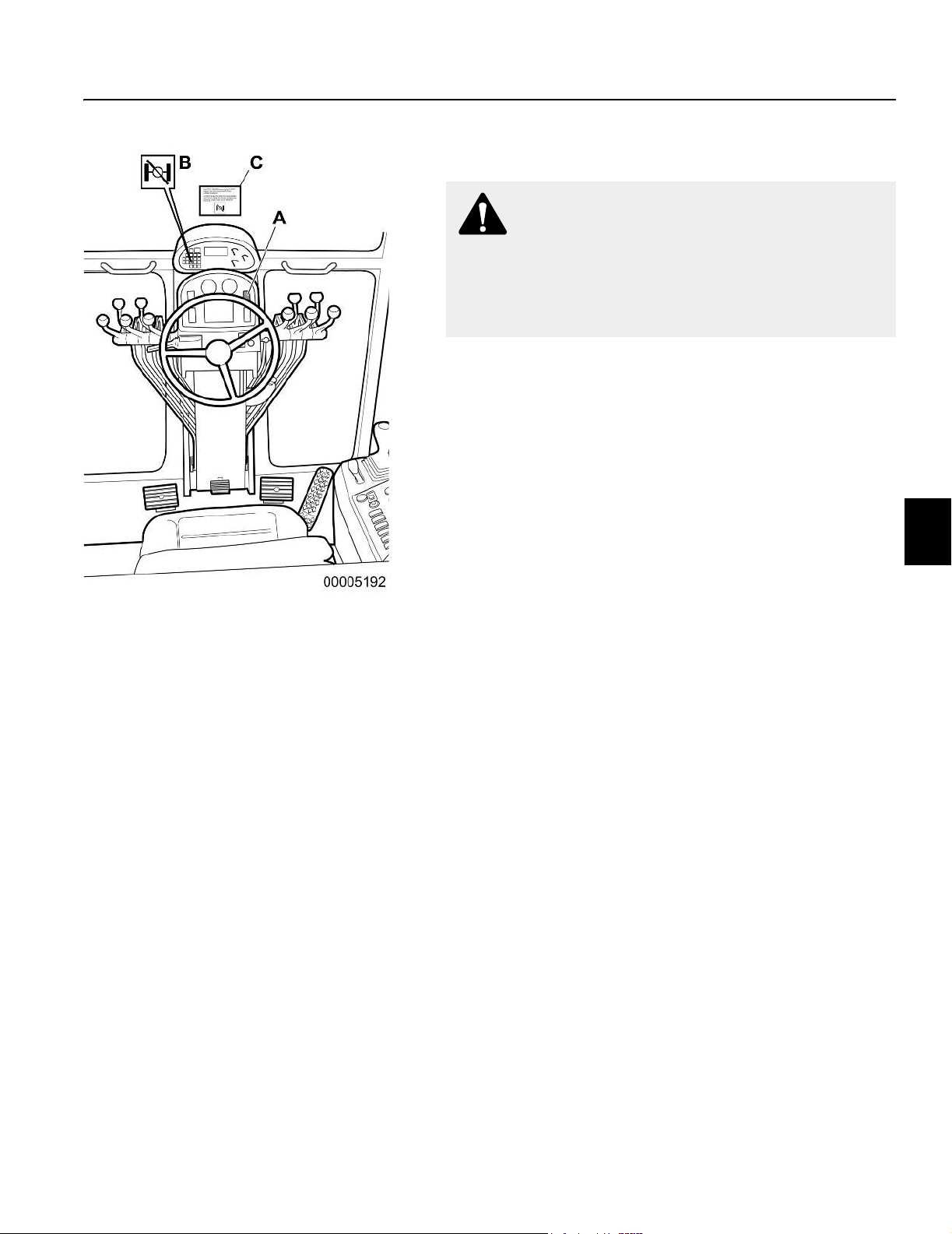
A Differential lock/unlock switch
B Differential lock indicator lamp (amber)
C Differential lock operating instructions decal
(on windshield)
Operating instructions
Differential lock 97
Differential lock
WARNING!
Lock or unlock the differential ONLY when driving at slow
speeds, in a straight line or if the grader is stopped. Do
not lock or unlock the differential while making a turn or
when the tandem wheels on one side are spinning.
Damage to the differential could result.
The lock/unlock differential control switch (A) is mounted in the
pedestal on the upper right-hand side. An amber lamp (B) illuminates when the lock is engaged.
n Put the control switch in the ‘UNLOCK’ position when differen-
tial action is required. This will reduce the turning radius and
decrease tire scuffing when operating on paved surfaces. The
indicator lamp will de-energize.
n Put the control switch in the ‘LOCK’ position for normal grad-
ing operations when maximum traction is required. The indicator lamp will energize.
n The DIFF UNLOCK warning light “OFF” means the lock/un-
lock mechanism is DISENGAGED.
n Do not engage the final drive lock/unlock mechanism while
the tandem wheels are spinning, under load, or the machine
is turning.

Operating instructions
98 After operating
After operating
WARNING!
When you are entering and leaving the machine, always
face the machine and use the steps or handholds to avoid
slipping. Always use the three-point stance, i.e. two hands
and one foot or two feet and one hand when climbing up
or descending from the machine. Do not jump!
General
When the machine is left unattended:
1 Apply the parking brake and when required (on a slope), block
the wheels so that the machine cannot roll.
2 Lower the moldboard and all attachments to the ground. Do not
apply down pressure.
3 Remove the ignition key.
4 Close the windows and lock the doors.
5 Turn off the battery isolation switch.
Stopping the machine
The machine is stopped as follows:
1 Release the accelerator to reduce engine speed.
2 Depress the clutch and brake the grader. (Depressing the clutch
only may not stop the machine.)
3 Move the transmission shift lever to neutral.
4 Apply the parking brake.
Use the brake pedal to hold the grader when transmission is in
gear with clutch pedal depressed and engine is running.
NOTE! Only apply the parking brake when the machine has
stopped. Always apply the brake if the machine is to be left
unattended.
Stopping the engine
NOTE! Run the engine at low idle for a few minutes before
stopping it to safeguard lubrication of the turbocharger.
1 Turn the ignition key counter-clockwise to the “O” position to
shut down the engine.
NOTE! If the machine is to be left for any length of time, turn
off the battery isolation switch.

Operating instructions
After operating 99
Parking
To park the grader:
n Always park the grader on a level surface.
n Stop the grader using the service brakes, then place the trans-
mission in NEUTRAL.
n Apply the parking brake.
n Lower the moldboard and all attachments to the ground. Do
not apply down-pressure.
n Shut down the engine.
n Remove and retain the ignition key.
n Turn the battery isolation switch OFF.
Long-term parking
When a grader is taken out of service for more than 30 days, you
must ensure that it is protected from exposure to the elements. An
enclosed structure will protect the grader from rapid temperature
changes and decrease the amount of condensation that forms in
fluid reservoirs, e.g., engine oil pan, fuel tank, hydraulic oil tank,
etc.
After you have parked the grader and shut down the engine, per-
form the following steps:
1 Inspect for leaks and other defects. Correct as necessary.
2 Thoroughly wash the grader. Be sure to rinse off any caustic
residue.
3 Touch up any areas where the paint has worn away.
4 Clean or replace air filter elements.
5 Open the drain valve at the bottom of the fuel tank and drain 1
liter (approx. 1 US quart) of fuel to remove any water accumulation.
6 Replace engine fuel filters.
7 Add the recommended amount of fuel stabilizer and corrosion
inhibitor to the fuel tank.
8 Start and run the engine at 1400 rpm to 1600 rpm with no load
for approximately four minutes.
9 Change the engine oil and replace the engine oil filter.
10 Properly seal the engine exhaust and air intake openings.
11 If tires are to be left on, raise the grader and place it on blocks
to keep the tires off the ground. Deflate and cover the tires.
12 Turn off the battery isolation switch. Remove batteries and store
them in a cool, clean, dry and well-ventilated area where the
temperature is be-tween 0°C and 21°C (32°F and 70°F). Be
sure batteries are fully charged.
13 Coat all machined and unpainted surfaces (including mold-
board) with grease to prevent rust forming.
14 Coat all exposed chrome plated surfaces on hydraulic cylinder
piston rods with a thin layer of grease.
15 Grease all door hinges.

Operating instructions
100 After operating
Preparing for operation after long-term parking
Perform the following steps before putting the grader back into
service:
1 Inspect for leaks and other defects which may have occurred
during storage.
2 Thoroughly wash the grader. Remove all grease and coatings
installed as Long term parking steps 13 and 14 on the previous page.
3 Remove any seals from the engine exhaust and air intake open-
ings.
4 Lubricate all grease points. See Grease points page 202.
5 Install fully charged batteries. Turn on the battery isolation
switch.
6 Inflate the tires to the correct pressure. Refer to Maximum tire
pressures page 196. Lower the grader from the storage blocks.
7 Perform all appropriate pre-start checks. Refer to Daily pre-start
checks page 81.
8 Start and run the engine at 1400 rpm to 1600 rpm with no load
for approximately four minutes. If any warning lamps and the
alarm energize or gauges show abnormal readings, shut down
the engine. Report the problem and have it repaired by a qualified service technician.
 Loading...