


Service Manual
Trucks
Group 37
Version 02
Wiring diagram
FM7, FM10, FM12 LHD
To be inserted into the binders for FM, FH.
TSP127085

Foreword
The descriptions and service procedures contained in this manual are based on designs and methods studies carried out up to December 1998.
The products are under continuous development. Vehicles and components produced after the above date may therefore have different specifications and repair methods. When this is judged to have a significant bearing on this manual, supplementary service bulletins will be issued to cover the changes.
The new edition of this manual will update the changes.
In service procedures where the title incorporates an operation number, this is a reference to V.S.T. (Volvo Standard Times).
Service procedures which do not include an operation number in the title are for general information and no reference is made to V.S.T.
The following levels of observations, cautions and warnings are used in this Service Documentation:
Note: Indicates a situation, handling or circumstance which should be observed.
Important: Indicates a situation, handling or circumstance which should be emphasized so as not to lead to personal injury or damage to property.
Caution: Indicates a potentially hazardous situation which, if not avoided, may result in minor or moderate injury or damage to property.
Warning: Indicates a potentially hazardous situation which, if not avoided, could result in death, serious injury or major damage to property.
Danger: Indicates an imminently hazardous situation which, if not avoided, will result in death or serious injury.
Volvo Truck Corporation
Göteborg, Sweden
The following information will be superseded by this manual:
SM Group 37 |
TSP 21847 |
Order number: TSP127085
© 1998 Volvo Truck Corporation, Göteborg, Sweden
All rights reserved. No part of this publication may be reproduced, stored in retrieval system, or transmitted in any forms by any means, electronic, mechanical, photocopying, recording or otherwise, without the prior written permission of Volvo Truck Corporation.
Contents |
|
Example of wiring diagram ................................................................... |
2 |
Examples of symbols on wiring diagram ........................................... |
3 |
Component wiring diagram index ....................................................... |
5 |
Component wiring diagrams ................................................................ |
7 |
Illustrations index ................................................................................ |
56 |
Illustrations ........................................................................................... |
58 |
Circuit card electrical centre ............................................................ |
125 |
Fuses on circuit card electrical centre ........................................... |
126 |
Relays on circuit card electrical centre .......................................... |
127 |
Cable harness illustration index ...................................................... |
128 |
List of connectors ............................................................................. |
132 |
List of components ........................................................................... |
140 |
Abbreviations ..................................................................................... |
146 |
Cable colour code ............................................................................. |
147 |
Feedback |
|
1
Group 37 Wiring diagram FM7, FM10, FM12 LHD |
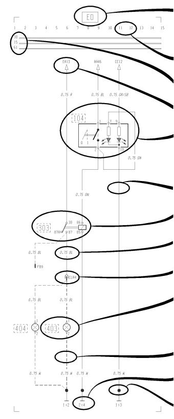
Example of wiring diagram |
Example of wiring diagram
Refer to the list of contents for the designation of the circuit diagram. If the circuit diagram designation is boxed in with broken lines this means that the circuit diagram is not standard on all market or vehicle models.
Seek column.
30 Voltage battery, kl.30.
15 Voltage with starting key in drive position, kl.15.
61 Voltage when alternator charges, kl.61.
Reference arrow (for circuit diagram EA, seek column 13).
Switch, comp. no. (104).
Single lines, cables.
Relay, comp. no. (303).
Cable area and colour (0.75 mm2 blue).
Connector (CLA terminal 4).
Bulb, comp. no. (403)
A broken line box round the component number shows that the component is not standard on all markets or vehicle models.
If the line is broken this means the cable is not standard on all markets or vehicle model.
Earth connection point no: 2. and earth terminal no: 4. (see diagram Earth Connections).
Joint sleeve.
T3009608
2
Group 37 Wiring diagram FM7, FM10, FM12 LHD |
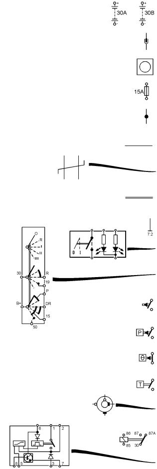
Examples of symbols on wiring diagram |
Examples of symbols on wiring diagram
Battery
Connector
Junktion
Fuse
Joint sleeve
Cable
Twisted cables
Conductor on circuit card
Earth connection and cable
Switch
Switch, starting switch
Closing contakt
Closing contakt, pressure-regulated
Break contakt, temperature-regulated
Closing contakt, time-regulated
Slip contakt, horn
Relay
Relay with internal circuit diagram
T3009609
3
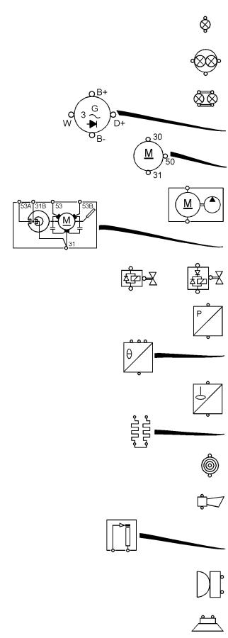
Group 37 Wiring diagram FM7, FM10, FM12 LHD |
Examples of symbols on wiring diagram |
Bulb
Bulb, full beams and dipped beams
Bulb, tail light
Alternator
Starter motor
Washer motor
Windscreen wiper motor
Solenoid valve with diode
Pressure sensor
Temperature sensor
Level sensor
Starting heater
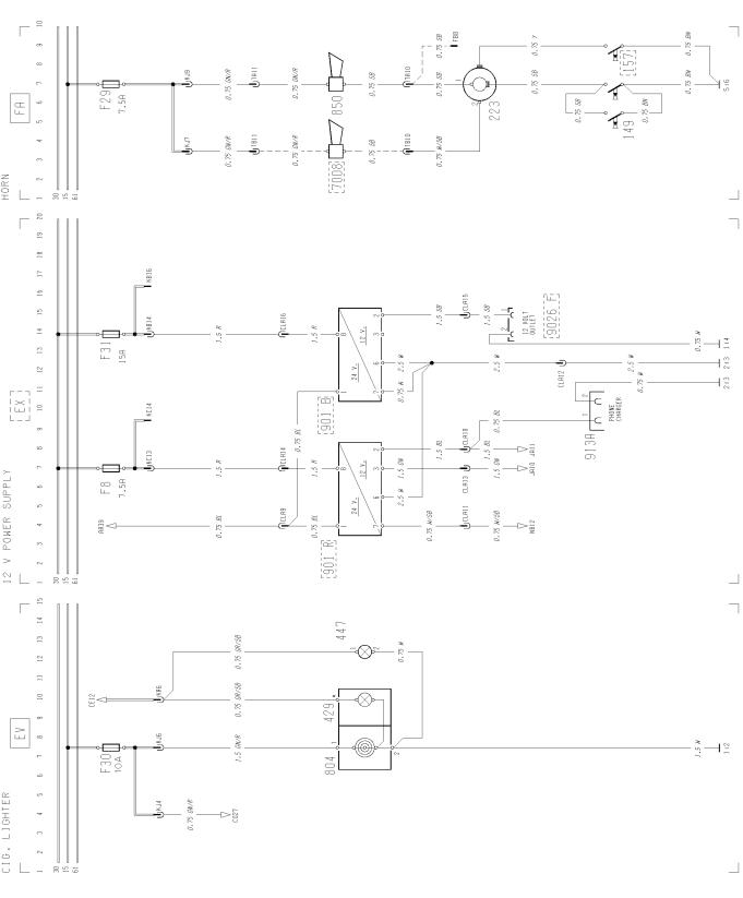
Cigarette lighter
Horn
Rheostat
Buzzer
Loudspeaker
T3009610
4
Group 37 Wiring diagram FM7, FM10, FM12 LHD |
Component wiring diagram index |
AA AC BJ BL BM CE CG CH CI CK CL CN EA ED EJ EK ER ES EV EX FA GA HA HB HC HD HE HG HH HK HM HP JA KA
Component wiring diagram index
Power supply, starting system, immobiliser ....................................................................
Vehicle ECU ....................................................................................................................
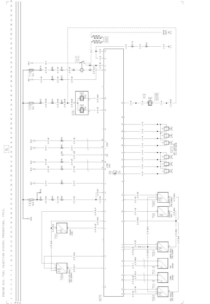
Engine ECU, fuel injection system, preheating, FM7 .....................................................
Engine ECU, fuel injection system, preheating, FM12 ...................................................
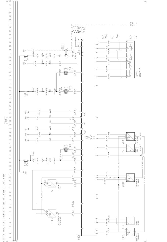
Engine ECU, fuel injection system, preheating, FM10 ...................................................
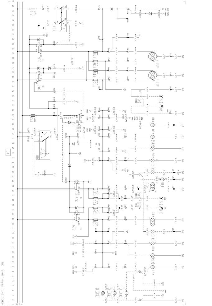
Head light, parking light, marker light, DRL ...................................................................
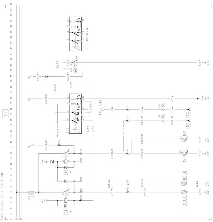
Fog light, rear fog light ....................................................................................................
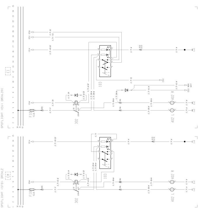
Spot light (STD) DRIVL2 .................................................................................................
Spot light (EU) DRIVL2EC ..............................................................................................
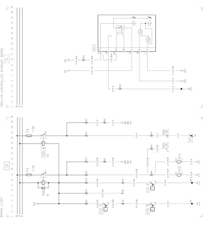
Brake light ........................................................................................................................
Trailer controlled exhaust brake ......................................................................................
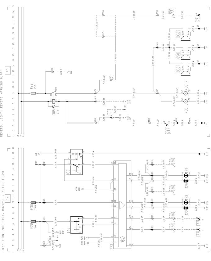
Direction indicator, hazard warning light .........................................................................
Reversing light, reversing warning alarm ........................................................................
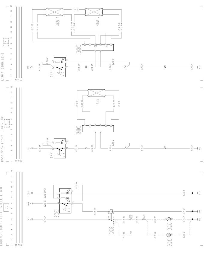
Loading light, fifth wheel light ..........................................................................................
Roof sign light, L1H1/L2H1 .............................................................................................
Roof sign light, L2H2 .......................................................................................................
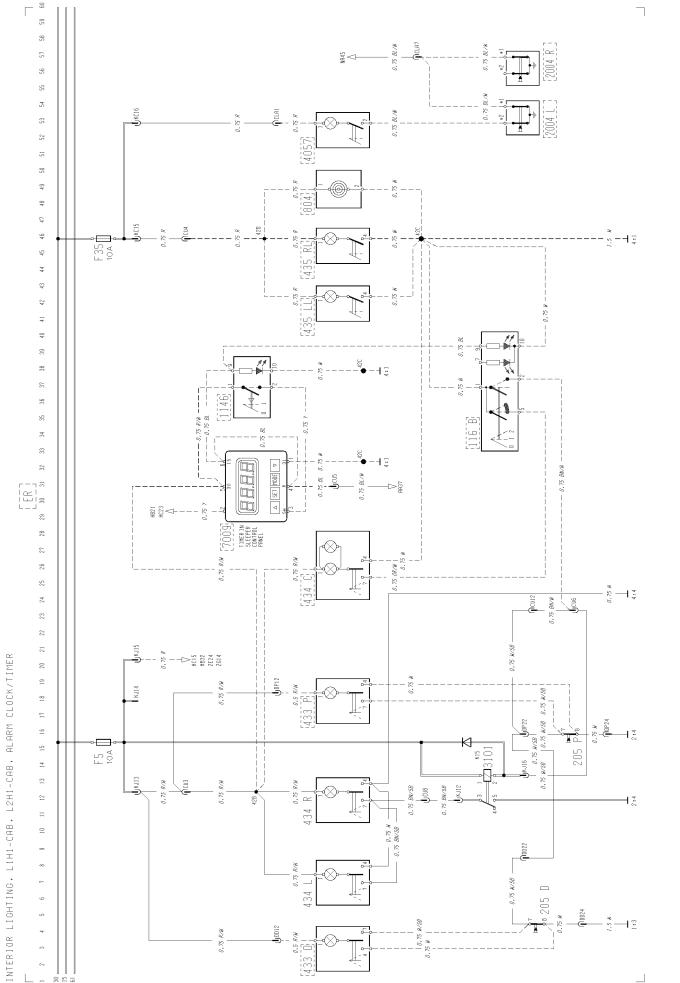
Interior light, L1H1/ L2H1, alarm clock/timer ..................................................................
Interior light, L2H2, alarm clock/timer .............................................................................
Cigarette lighter ...............................................................................................................
12 V power supply ...........................................................................................................
Horn .................................................................................................................................
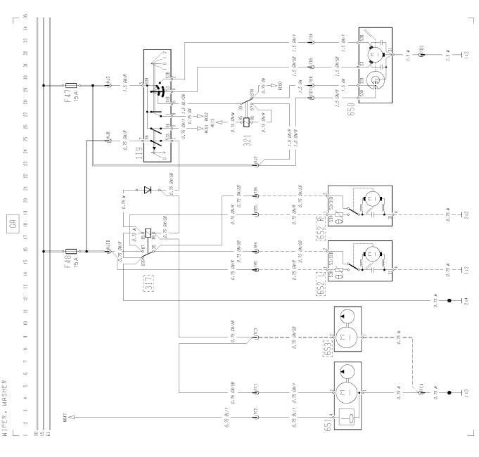
Wiper, washer ..................................................................................................................
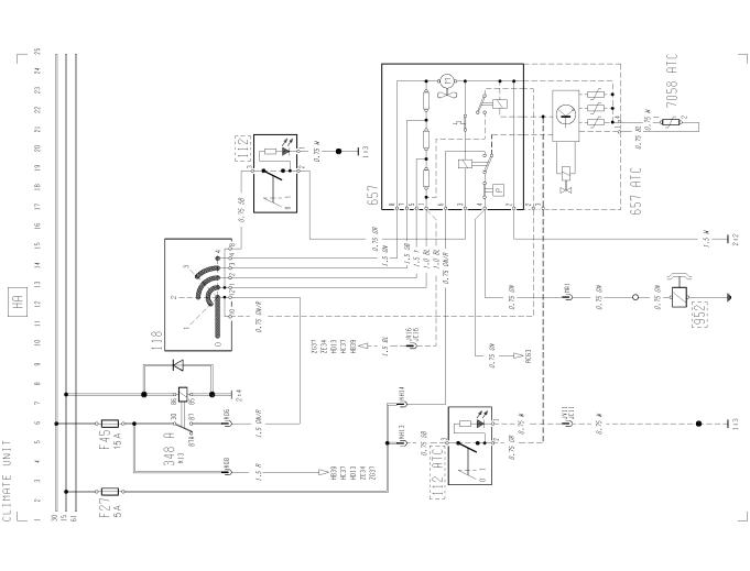
Climate unit .....................................................................................................................
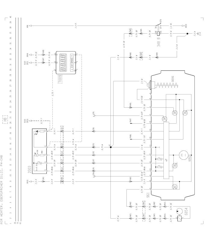
Cab heater, EBERSPÄCHER D1LCC, PH-CAB .............................................................
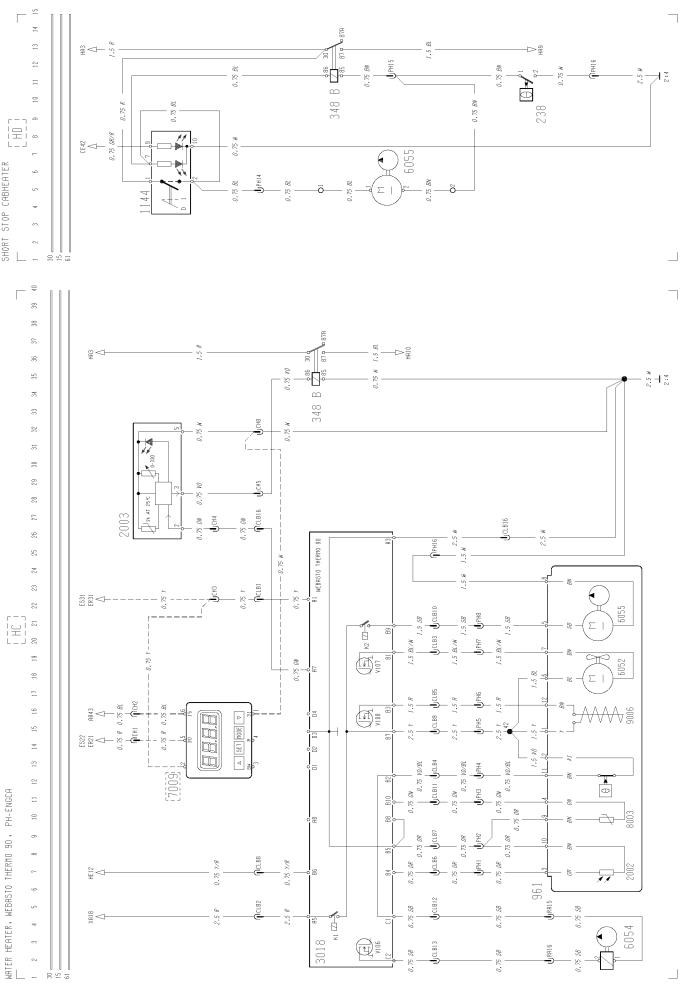
Cab and engine heater, WEBASTO THERMO 90, PH-ENGCA ....................................
Short stop cabheater .....................................................................................................
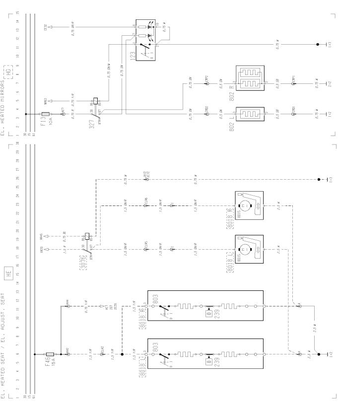
Electrically heated and adjusted seat .............................................................................
Electrically heated mirrors ...............................................................................................
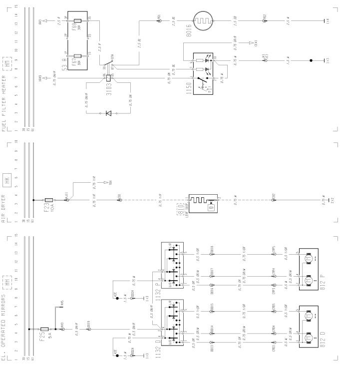
Electrically operated mirrors ............................................................................................
Air dryer ...........................................................................................................................
Fuel filter heater ..............................................................................................................
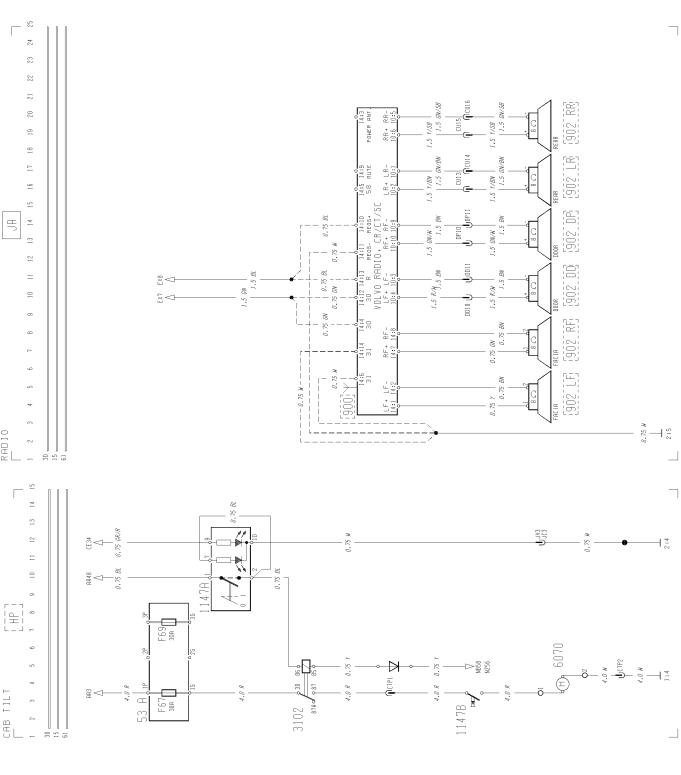
Electrically cab tilt ..........................................................................................................
Radio ...............................................................................................................................
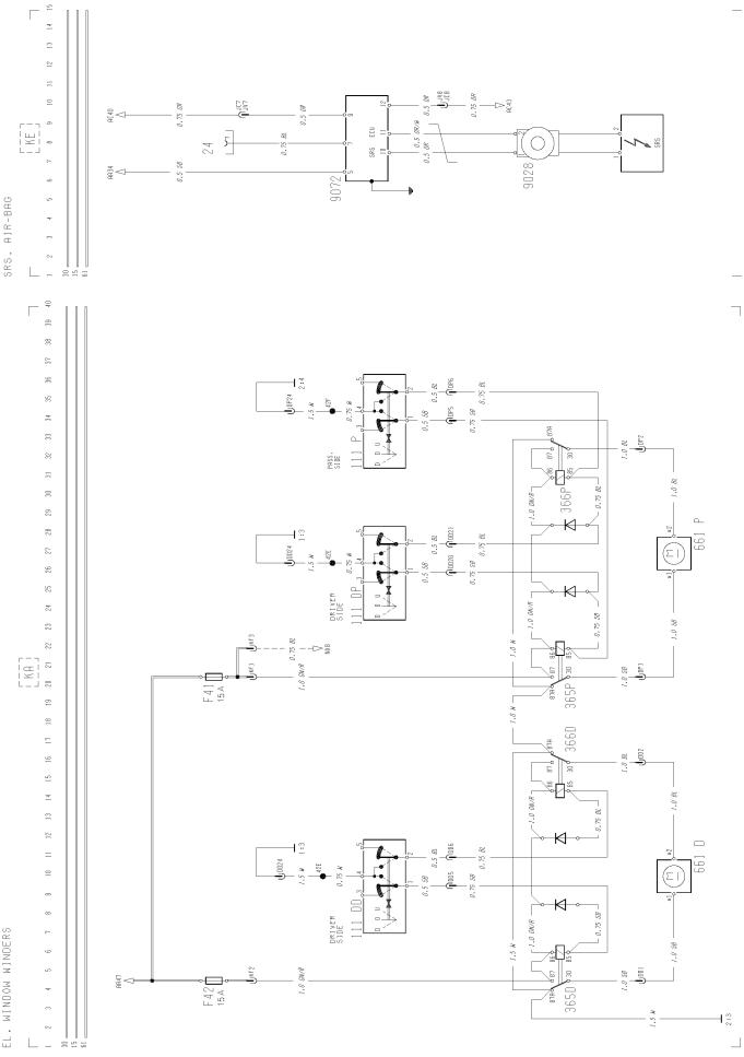
Electrically operated window winders .............................................................................
page 7 page 8 page 9 page 10 page 11 page 12
page 13
page 14
page 14
page 15
page 15
page 16
page 16
page 17
page 17
page 17
page 18
page 19
page 20
page 20
page 20
page 21
page 22
page 23
page 24
page 24
page 25
page 25
page 26
page 26
page 26
page 27
page 27
page 28
5
Group 37 Wiring diagram FM7, FM10, FM12 LHD |
Component wiring diagram index |
KE KH LD LE LG LJ LL LO LP LS MA MD ME MF MG NA NB NC NX NZ OA OB OG PA PD TA TB XA ZA ZB ZD ZE ZG
SRS, air-bag ....................................................................................................................
Central door lock .............................................................................................................
Power take-off ..................................................................................................................
Double power take-off .....................................................................................................
Differential lock ................................................................................................................
Bogie lift, tag axle lock, RADT-LA ...................................................................................
Tag axle lock, RADT-A6S ................................................................................................
Geartronic, automatic gearshift .......................................................................................
Powertronic ......................................................................................................................
GLU, gear selector, Geartronic .......................................................................................
Bogie lift hydraulic, RADT-AR .........................................................................................
Bogie lift hydraulic, with axle load limiter, RADT-AR ......................................................
Air suspension, 6x2/6x4/8x2/8x4, SUSPL-EC ................................................................
Air suspension, 4x2, SUSPL-EC .....................................................................................
Rear air suspension, 4x2, TRACTOR, SUSPL-EC .........................................................
Instrument LHS module ..................................................................................................
Instrument central module with tachograph ....................................................................
Instrument RHS module ..................................................................................................
Dynafleet ....................................................................................................................... ..
Instrument central module without tachograph ...............................................................
Basic ABS, D-version ......................................................................................................
ABS/ASR, D-version ........................................................................................................
Retarder, manual gearshift ..............................................................................................
Headlight level control .....................................................................................................
Dual speed limiter ...........................................................................................................
Refrigerator ......................................................................................................................
Central lubrication system ...............................................................................................
Extra fuses, key switch relay ...........................................................................................
Earth connections ...........................................................................................................
Earth connections ...........................................................................................................
ADR battery main switch, current limiter .......................................................................
Air heater EBERSPÄCHER D1LCC, TRS ......................................................................
Water heater, WEBASTO THERMO 90, TRS .................................................................
page 28
page 29
page 29
page 30
page 30
page 31
page 31
page 32
page 33
page 34
page 35
page 36
page 37
page 38
page 39
page 40
page 41 page 42 page 43 page 44
page 45
page 46
page 47
page 48
page 48
page 49
page 49
page 50
page 51
page 52
page 53
page 54
page 55
6
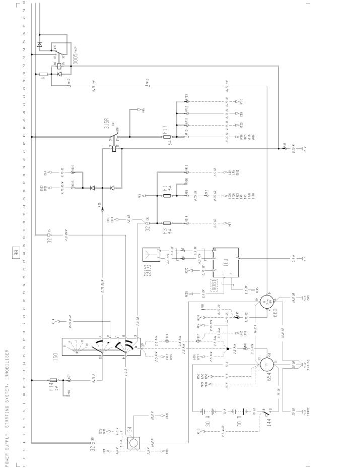
Group 37 Wiring diagram FM7, FM10, FM12 LHD |
Component wiring diagrams |
Component wiring diagrams
T3011387
7

Group 37 Wiring diagram FM7, FM10, FM12 LHD |
Component wiring diagrams |
T3011388
8
Group 37 Wiring diagram FM7, FM10, FM12 LHD |
Component wiring diagrams |
T30113899
Group 37 Wiring diagram FM7, FM10, FM12 LHD |
Component wiring diagrams |
T3011390
10
Group 37 Wiring diagram FM7, FM10, FM12 LHD |
Component wiring diagrams |
T3011391
11
Group 37 Wiring diagram FM7, FM10, FM12 LHD |
Component wiring diagrams |
T3011392
12
Group 37 Wiring diagram FM7, FM10, FM12 LHD |
Component wiring diagrams |
T3011498
13
Group 37 Wiring diagram FM7, FM10, FM12 LHD |
Component wiring diagrams |
T3011393
14
Group 37 Wiring diagram FM7, FM10, FM12 LHD |
Component wiring diagrams |
T3011394
15
Group 37 Wiring diagram FM7, FM10, FM12 LHD |
Component wiring diagrams |
T3011395
16
Group 37 Wiring diagram FM7, FM10, FM12 LHD |
Component wiring diagrams |
T3011396
17
Group 37 Wiring diagram FM7, FM10, FM12 LHD |
Component wiring diagrams |
T3011397
18
Group 37 Wiring diagram FM7, FM10, FM12 LHD |
Component wiring diagrams |
T3011398
19
Group 37 Wiring diagram FM7, FM10, FM12 LHD |
Component wiring diagrams |
T3011399
20
Group 37 Wiring diagram FM7, FM10, FM12 LHD |
Component wiring diagrams |
T3011400
21
Group 37 Wiring diagram FM7, FM10, FM12 LHD |
Component wiring diagrams |
T3011401
22
Group 37 Wiring diagram FM7, FM10, FM12 LHD |
Component wiring diagrams |
T3011402
23
Group 37 Wiring diagram FM7, FM10, FM12 LHD |
Component wiring diagrams |
T3011403
24
Group 37 Wiring diagram FM7, FM10, FM12 LHD |
Component wiring diagrams |
T3011404
25
Group 37 Wiring diagram FM7, FM10, FM12 LHD |
Component wiring diagrams |
T3011405
26
Group 37 Wiring diagram FM7, FM10, FM12 LHD |
Component wiring diagrams |
T3011406
27
Group 37 Wiring diagram FM7, FM10, FM12 LHD |
Component wiring diagrams |
T3011407
28
 Loading...