


Service Manual
Trucks
Group 37
Wiring Diagram
FL6 LHD
CHID B166080–
TSP 23769/1
Foreword
The descriptions and service procedures contained in this manual are based on design and method studies placed up to August 1996.
The products are under continuous development. Vehicles and components produced after the above date may therefore have different specifications and repair methods. When this is judged to have a significant bearing on this manual, supplementary service bulletins will be issued to cover the changes.
The new edition of this manual will update the changes.
In service procedures where the title incorporates an operation number, this is a reference to V.S.T. (Volvo Standard Times).
Service procedures which do not include an operation number in the title are for general information and no reference is made to V.S.T.
The following levels of observations, cautions and warnings are used in this Service Documentation:
Note: Indicates a situation, handling or circumstance which should be observed.
Important: Indicates a situation, handling or circumstance which should be emphasized so as not to lead to personal injury or damage to property.
Caution: Indicates a potentially hazardous situation which, if not avoided, may result in minor or moderate injury or damage to property.
Warning: Indicates a potentially hazardous situation which, if not avoided, could result in death, serious injury or major damage to property.
Danger: Indicates an imminently hazardous situation which, if not avoided, will result in death or serious injury.
Volvo Truck Corporation
Go¨teborg, Sweden
Order number: TSP 23769/1
© 1996 Volvo Truck Corporation, Go¨ teborg, Sweden
All rights reserved. No part of this publication may be reproduced, stored in retrieval system, or transmitted in any forms by any means, electronic, mechanical, photocopying, recording or otherwise, without the prior written permission of Volvo Truck Corporation.
Contents |
|
Component wiring diagram index ....................................................... |
2 |
Component wiring diagrams ................................................................ |
5 |
Illustrations ........................................................................................... |
32 |
Fuses on circuit board (32) electrical centre ................................... |
85 |
Fuses ..................................................................................................... |
86 |
Relays on circuit board (32) electrical centre .................................. |
86 |
Cable harness illustration index ........................................................ |
87 |
List of connectors ............................................................................... |
90 |
List of components ............................................................................. |
93 |
Abbreviations ....................................................................................... |
96 |
Cable colour code ............................................................................... |
96 |
Feedback |
|
1

Group 37 Wiring Diagram FL6 LHD |
Component wiring diagram index |
Component wiring diagram index
Starter system ...................................................................................... |
page 5 |
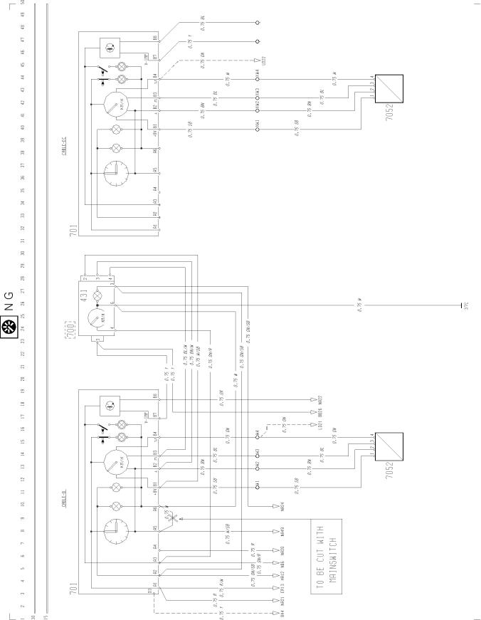
Coolant level, coolant temperature, |
|
preheating, exhaust pressure governor, |
page 6 |
exhaust brake, range inhibitor, interval wipe ......... |
|
Engine control, Supercharger .............................................................. |
page 6 |
Engine shut-off ..................................................................................... |
page 7 |
Speed limitation .................................................................................... |
page 7 |
Head lights, position lights, marker lights, DRL, spotlights ................. |
page 8 |
Front fog lights ..................................................................................... |
page 9 |
Brake lights ........................................................................................... |
page 9 |
Direction indicators, hazard warning lights .......................................... |
page 9 |
Reversing lights, reversing warning ..................................................... |
page 10 |
Loading light, fifth wheel light ............................................................... |
page 10 |
Rear fog lights ...................................................................................... |
page 10 |
Rotating warning light ........................................................................... |
page 11 |
Interior lights ......................................................................................... |
page 11 |
Cigarette lighter .................................................................................... |
page 11 |
Horn |
page 11 |
|
2

Group 37 Wiring Diagram FL6 LHD |
Component wiring diagram index |
|
Windscreen wipers and washers, headlamp wipers and washers .... |
page 12 |
|
Climate unit ........................................................................................ |
|
page 12 |
Cab heater, PH-CAB |
|
page 13 |
|
|
|
Cab and engine heater, PH-ENGCA |
|
page 14 |
|
|
|
Electrically heated seat ...................................................................... |
|
page 15 |
Electrically heated mirror .................................................................... |
|
page 15 |
Electrically operated mirror ................................................................ |
|
page 15 |
Air dryer .............................................................................................. |
|
page 15 |
Fuel filter heater |
|
page 16 |
|
|
|
City filter ............................................................................................. |
|
page 16 |
Radio, voltage divider, loudspeaker ................................................... |
|
page 17 |
Electrically operated window winder .................................................. |
|
page 17 |
Electrically operated passenger door lock |
|
page 18 |
|
|
|
Power take-off .................................................................................... |
|
page 18 |
Power take-off, clutch-independent .................................................... |
|
page 19 |
Automatic transmission, SKMT 113, SKMT 137 ............................... |
|
page 19 |
Diff. lock .............................................................................................. |
|
page 20 |
3

Group 37 Wiring Diagram FL6 LHD |
Component wiring diagram index |
Automatic transmission |
page 20 |
|
|
Split |
page 20 |
|
|
Bogie lift hydralic |
page 21 |
|
|
Air suspension .................................................................................... |
page 21 |
Instrument unit .................................................................................... |
page 22 |
Indicator lamps ................................................................................... |
page 23 |
Tachograph, speedometer ................................................................. |
page 24 |
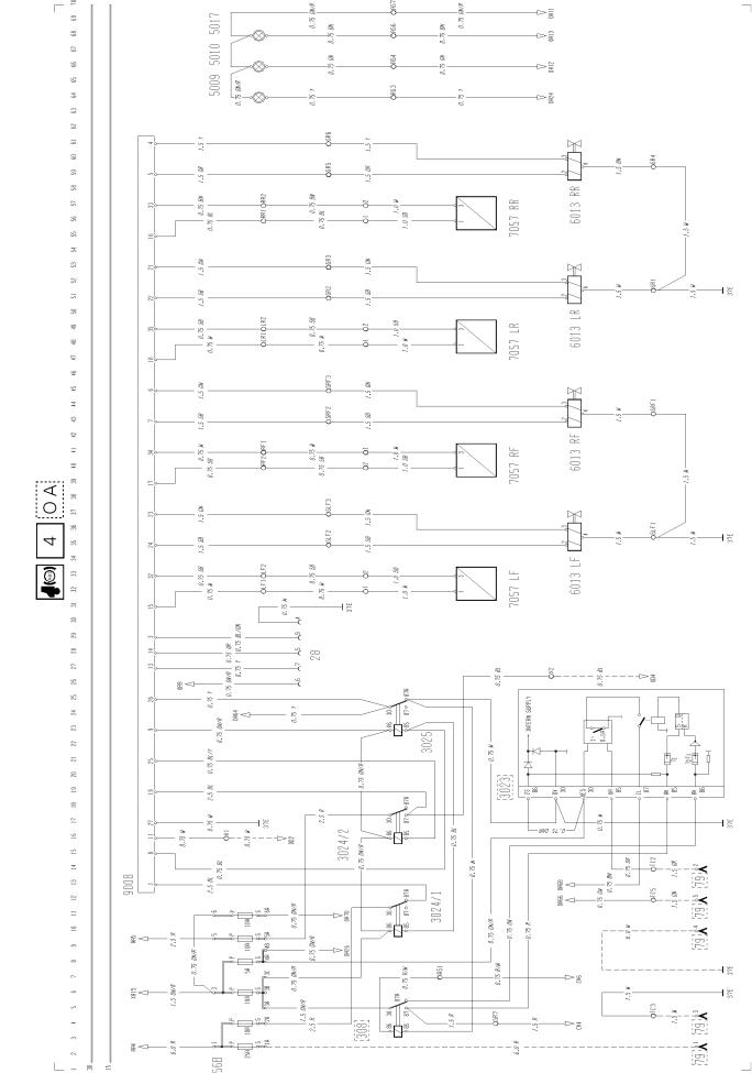
Anti-lock brakes (ABS) 4-channel ...................................................... |
page 25 |
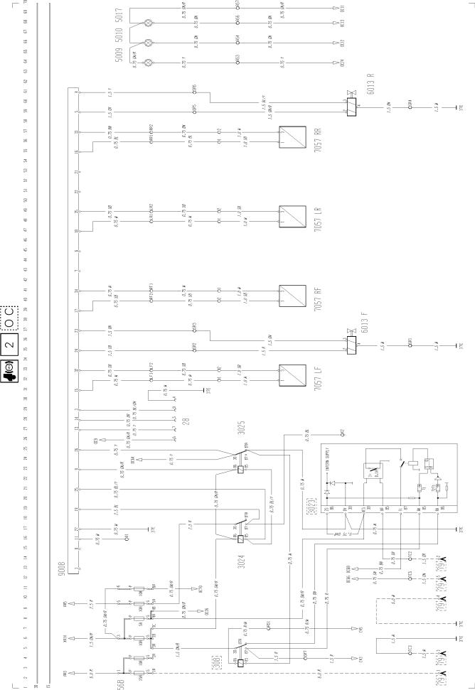
Anti-lock brakes (ABS) 2-channel ...................................................... |
page 26 |
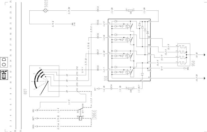
Retarder (electro-magnetic) ............................................................... |
page 27 |
Headlight level control ........................................................................ |
page 28 |
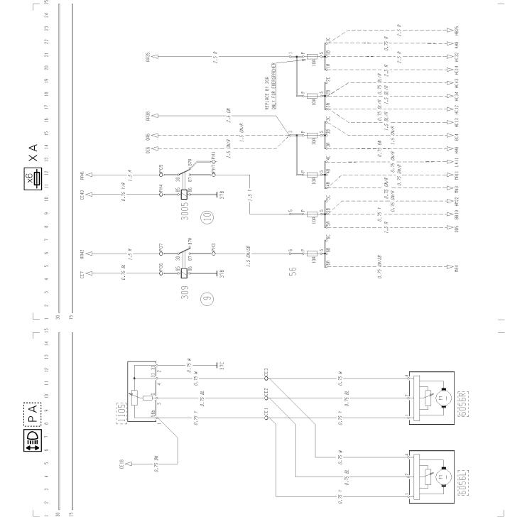
Extra fuses ......................................................................................... |
page 28 |
Spare relay ......................................................................................... |
page 29 |
Extra connection ................................................................................. |
page 29 |
Earth connections ............................................................................... |
page 30 |
ADR-FRA ............................................................................................ |
page 31 |
4
Group 37 Wiring Diagram FL6 LHD |
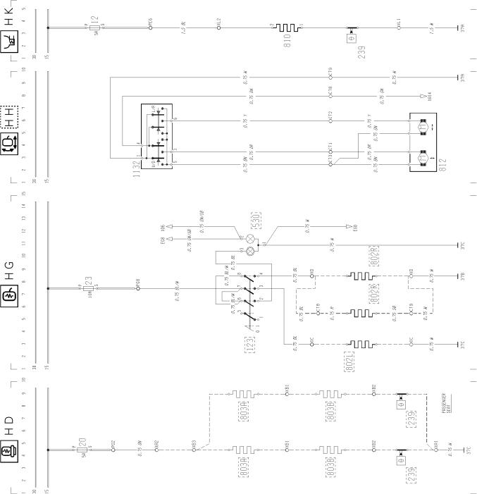
Component wiring diagrams |
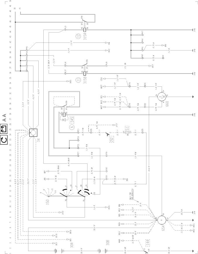
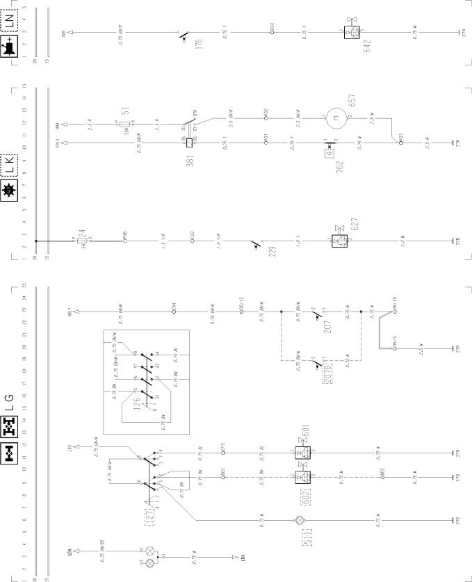
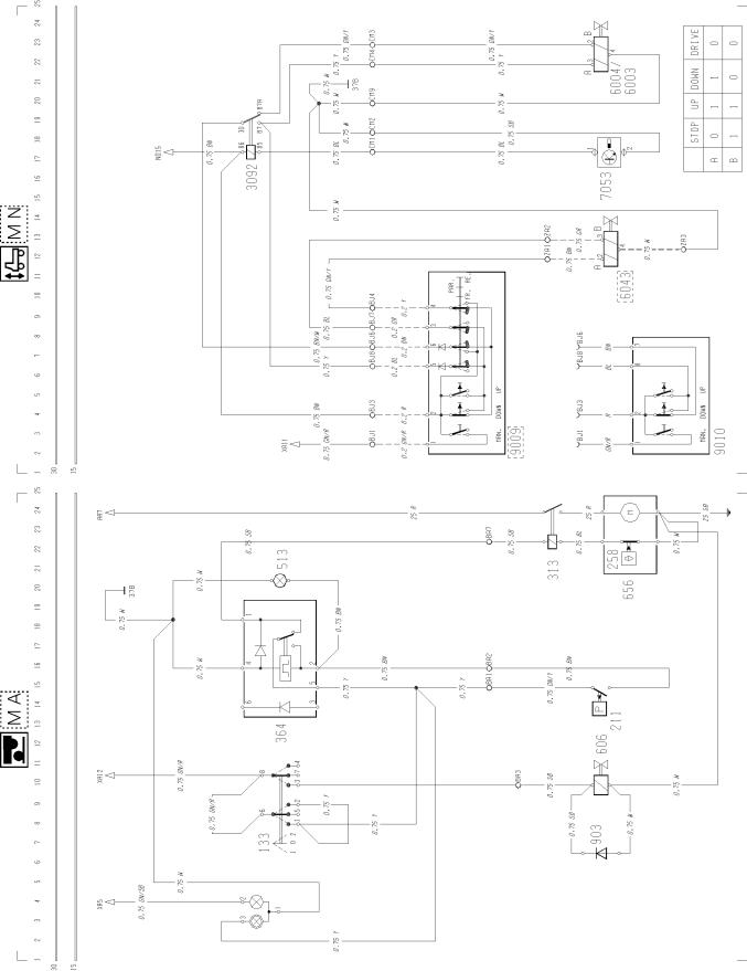
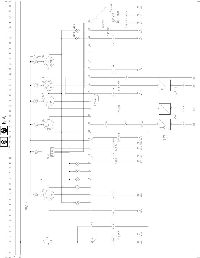
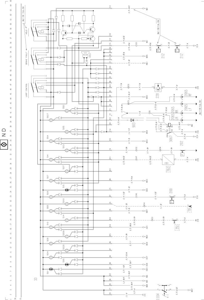
Component wiring diagrams
T3008442
5
Group 37 Wiring Diagram FL6 LHD |
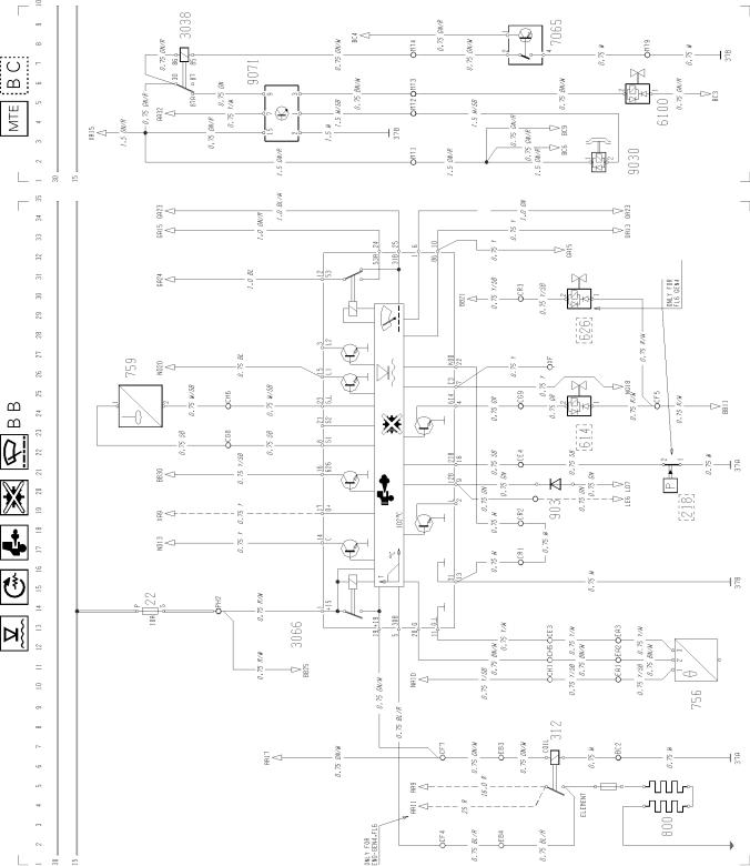
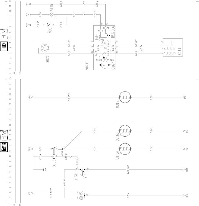
Component wiring diagrams |
T3008443
6
Group 37 Wiring Diagram FL6 LHD |
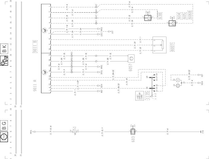
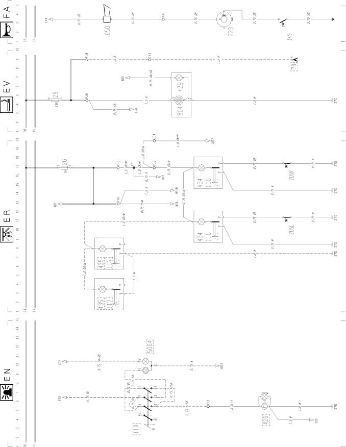
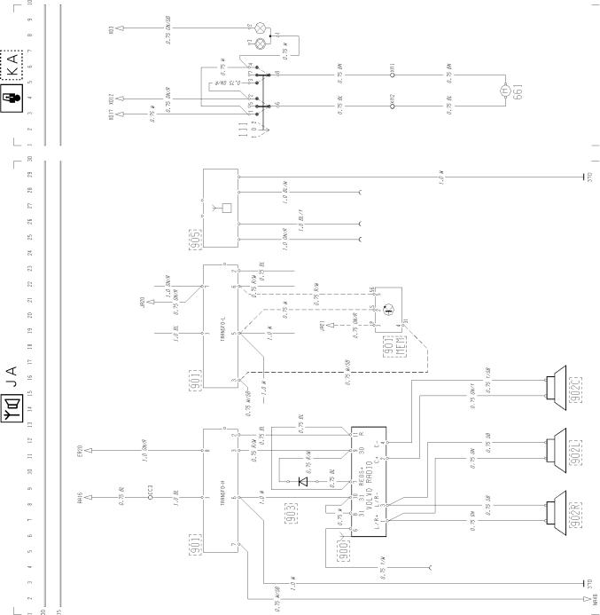
Component wiring diagrams |
T3008444
7

Group 37 Wiring Diagram FL6 LHD |
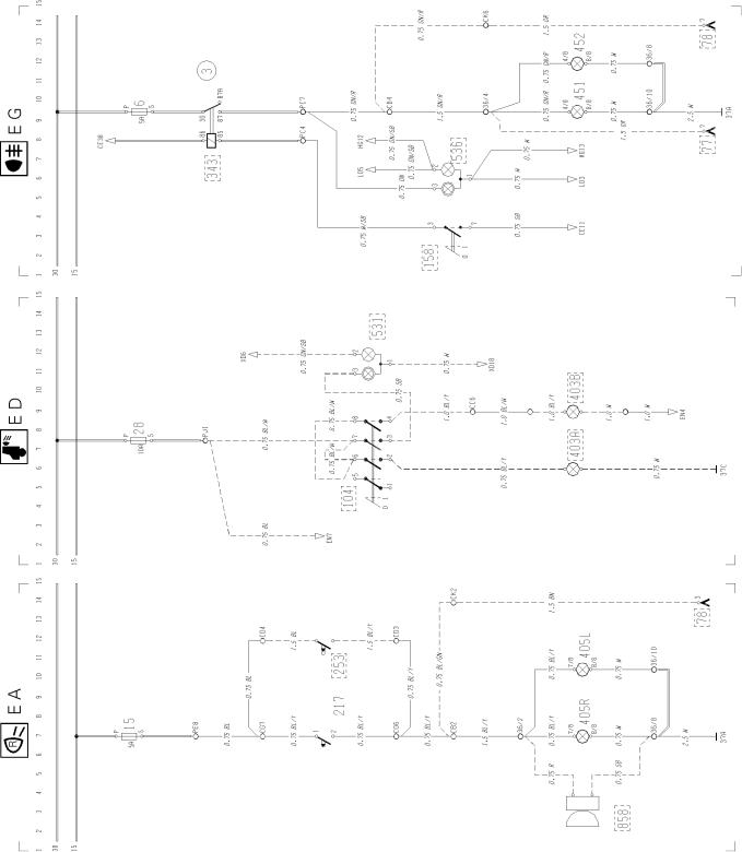
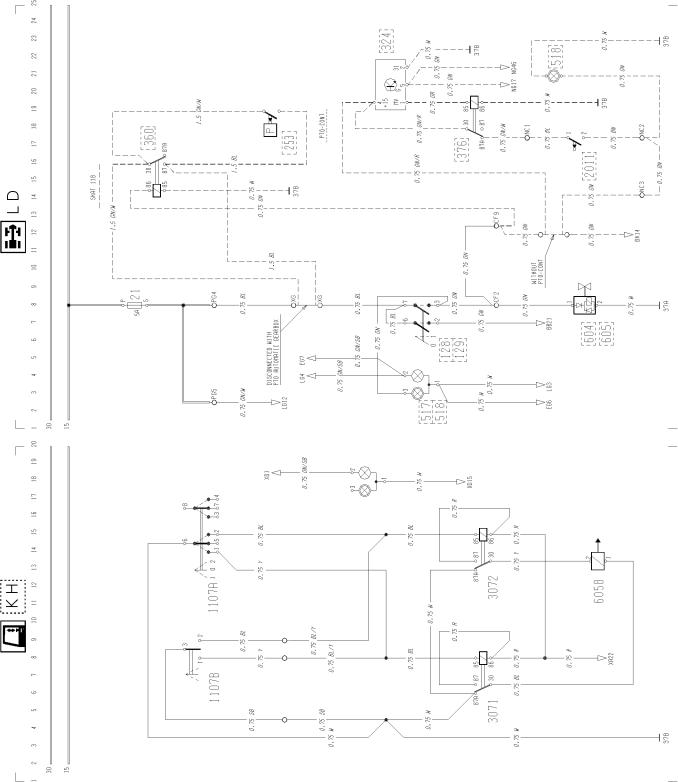
Component wiring diagrams |
T3008445
8
Group 37 Wiring Diagram FL6 LHD |
Component wiring diagrams |
T30084469
Group 37 Wiring Diagram FL6 LHD |
Component wiring diagrams |
T3008447
10
Group 37 Wiring Diagram FL6 LHD |
Component wiring diagrams |
T3008448
11
Group 37 Wiring Diagram FL6 LHD |
Component wiring diagrams |
T3008449
12
Group 37 Wiring Diagram FL6 LHD |
Component wiring diagrams |
T3008450
13
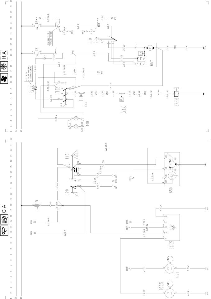
Group 37 Wiring Diagram FL6 LHD |
Component wiring diagrams |
T3008451
14
Group 37 Wiring Diagram FL6 LHD |
Component wiring diagrams |
T3008452
15
Group 37 Wiring Diagram FL6 LHD |
Component wiring diagrams |
T3008453
16
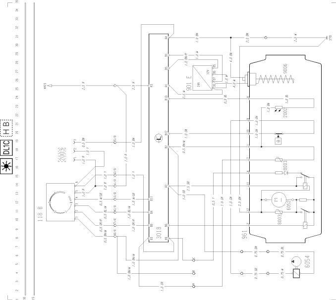
Group 37 Wiring Diagram FL6 LHD |
Component wiring diagrams |
T3008454
17
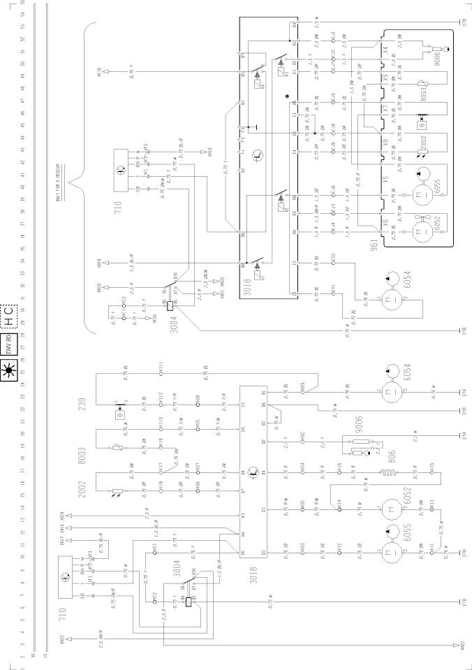
Group 37 Wiring Diagram FL6 LHD |
Component wiring diagrams |
T3008455
18
Group 37 Wiring Diagram FL6 LHD |
Component wiring diagrams |
T3008456
19
Group 37 Wiring Diagram FL6 LHD |
Component wiring diagrams |
T3008457
20
Group 37 Wiring Diagram FL6 LHD |
Component wiring diagrams |
T3008458
21
Group 37 Wiring Diagram FL6 LHD |
Component wiring diagrams |
T3008459
22
Group 37 Wiring Diagram FL6 LHD |
Component wiring diagrams |
T300846023
Group 37 Wiring Diagram FL6 LHD |
Component wiring diagrams |
T3008461
24
Group 37 Wiring Diagram FL6 LHD |
Component wiring diagrams |
T3008462
25
Group 37 Wiring Diagram FL6 LHD |
Component wiring diagrams |
T3008463
26
Group 37 Wiring Diagram FL6 LHD |
Component wiring diagrams |
T3008464
27
Group 37 Wiring Diagram FL6 LHD |
Component wiring diagrams |
T3008465
28
 Loading...