

Page 1
VOLVO S40
Owners Manual
WEB EDITION
Page 2
DEAR VOLVO OWNER
THANK YOU FOR CHOOSING VOLVO
We hope you will enjoy many years of driving pleasure in your
Volvo. The car has been designed for the safety and comfort of
you and your passengers. Volvo is one of the safest cars in the
world. Your Volvo has also been designed to satisfy all current
safety and environmental requirements.
In order to increase your enjoyment of the car, we recommend
that you familiarise yourself with the equipment, instructions
and maintenance information contained in this owner's manual.
Page 3
Table of contents
00 Introduction
Important information................................. 8
Volvo and the environment....................... 11
00
01 Safety
Seatbelts................................................... 16
Airbag system........................................... 19
Airbags (SRS)............................................ 20
Activating/deactivating the airbag (SRS)*. 23
Side airbags (SIPS bags).......................... 25
Inflatable Curtain (IC)................................ 27
WHIPS....................................................... 28
When the systems deploy......................... 30
Crash mode.............................................. 31
Child safety............................................... 32
01
02 Instruments and controls
Overview, left-hand drive cars.................. 40
Overview, right-hand drive cars................ 42
Driver's door control panel....................... 44
Combined instrument panel...................... 45
Indicator and warning symbols................. 46
Information display................................... 50
Electrical socket........................................ 52
Lighting panel........................................... 53
Left-hand stalk switch............................... 56
Right-hand stalk switch............................ 59
Cruise control*.......................................... 61
Keypad in the steering wheel*.................. 63
Steering wheel adjustment, hazard warn-
ing flashers................................................ 64
Parking brake............................................ 65
02
Power windows......................................... 66
Rearview and door mirrors....................... 68
Power sunroof*......................................... 72
Personal preferences................................ 73
HomeLink
EU*......................................... 76
2
* Option/accessory, for more information, see Introduction.
Page 4
Table of contents
03 Climate control
General information on climate control..... 82
Manual climate control, AC....................... 84
Electronic climate control, ECC*............... 87
Air distribution........................................... 91
Fuel-driven engine block heater and pas-
senger compartment heater*.................... 92
Fuel-driven auxiliary heater* (diesel)......... 95
03
04 Interior
Front seats................................................ 98
Interior lighting........................................ 100
Storage spaces in the passenger com-
partment.................................................. 102
Rear seat................................................. 106
Cargo area.............................................. 108
04
05 Locks and alarm
Remote control with key blade............... 112
Privacy locking*....................................... 115
Active locks............................................. 116
Keyless drive*.......................................... 117
Battery in remote control........................ 120
Locking and unlocking............................ 121
Child safety locks.................................... 124
Alarm*...................................................... 125
05
* Option/accessory, for more information, see Introduction.
3
Page 5
Table of contents
06 Starting and driving
General.................................................... 130
Refuelling................................................ 132
Starting the engine.................................. 133
Starting the engine – Flexifuel................. 135
Keyless drive*.......................................... 137
Manual gearbox...................................... 138
Automatic gearbox.................................. 140
All-wheel drive......................................... 144
Brake system.......................................... 145
DSTC – Stability and traction control sys-
tem*......................................................... 147
Park Assist*............................................. 149
BLIS* – Blind Spot Information System. . 151
Towing and recovery.............................. 155
Start assistance...................................... 157
06
Driving with a trailer................................ 158
Towing equipment*................................. 160
Detachable towbar*................................ 162
Loading................................................... 166
Adjusting headlamp pattern.................... 167
07 Wheels and tyres
General.................................................... 170
Tyre pressure.......................................... 174
Warning triangle* and spare wheel......... 177
Changing wheels.................................... 180
Emergency puncture repair*................... 182
07
08 Car care
Cleaning.................................................. 188
Touching up paintwork........................... 191
Rustproofing........................................... 192
08
4
* Option/accessory, for more information, see Introduction.
Page 6
Table of contents
09 Maintenance and service
Volvo service........................................... 196
Self-maintenance.................................... 197
Bonnet and engine compartment........... 198
Oils and fluids......................................... 199
Wiper blades........................................... 204
Battery..................................................... 205
Replacing bulbs...................................... 207
Fuses....................................................... 214
09
10 Infotainment system
General.................................................... 224
Audio functions....................................... 226
Radio functions....................................... 230
CD functions........................................... 235
Menu structure – audio system.............. 238
Phone functions*..................................... 239
Menu structure – phone*......................... 246
Bluetooth handsfree*.............................. 249
10
11 Specifications
Type designation..................................... 256
Dimensions and weights......................... 258
Engine specifications.............................. 260
Engine oil................................................ 262
Fluids and lubricants............................... 266
Fuel......................................................... 269
Catalytic converter.................................. 274
Electrical system..................................... 275
Type approval......................................... 277
11
* Option/accessory, for more information, see Introduction.
5
Page 7
Table of contents
12 Alphabetical Index
Alphabetical Index.................................. 278
12
6
Page 8
Table of contents
7
Page 9
Introduction
Important information
Reading the Owner's Manual
Introduction
A good way of getting to know your new car is
to read the owner's manual, ideally before your
first journey. This will give you the opportunity
to familiarise yourself with new functions, to
see how best to handle the car in different situations, and to make the best use of all the
car's features. Please pay attention to the
safety instructions contained in the manual.
The equipment described in the owner's manual is not present in all cars. In addition to
standard equipment, this manual also
describes options (factory fitted equipment)
and certain accessories (retrofitted extra
equipment). If you are uncertain over what is
standard or option/accessory then contact
your Volvo dealer.
Volvo cars are adapted for the varying requirements of different markets, as well as for
national or local legal requirements and regulations.
The specifications, design features and illustrations in this owner's manual are not binding.
We reserve the right to make modifications
without prior notice.
© Volvo Car Corporation
Option
All types of option/accessory are marked with
an asterisk .
The range of options/accessories for the different car models varies depending on the market. The majority of options are factory fitted
and cannot be retrofitted, accessories are retrofitted.
Contact your authorised Volvo dealer for more
information.
Special texts
WARNING
Warning texts advise of a risk of personal
injury.
IMPORTANT
Important texts advise of a risk of material
damage.
NOTE
NOTE texts give advice or tips that facilitate
the use of features and functions for example.
Footnote
There is footnote information in the owner's
manual that is located at the bottom of the
page. This information is an addition to the text
that it refers to via a number. If the footnote
refers to text in a table then letters are used
instead of numbers for referral.
Message texts
There are displays in the car that show text
messages. These text messages are highlighted in the owner's manual by means of the
text being slightly larger and printed in grey.
Examples of this are in menu texts and message texts on the information display (e.g.
Audio settings).
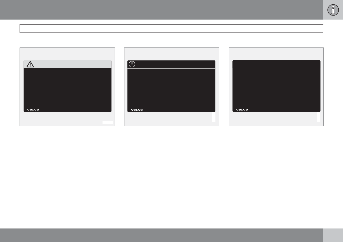
Decals
The car contains different types of decal which
are designed to convey important information
in a simple and clear manner. The decals in the
car have the following descending degree of
importance for the warning/information.
8
Page 10
Introduction
G031593
Important information
Warning for personal injury
G031590
Black ISO symbols on yellow warning field,
white text/image on black message field. Dangerous situation which, if not avoided, may
result in serious personal injury or fatality.
Risk of property damage
White ISO symbols on black symbol field, white
text/image on black message field. If a colour
is required then the decal shall be blue. Dangerous situation which, if not avoided, may
result in minor or moderate damage to property.
Information
G031592
White ISO symbols and white text/image on
black message field.
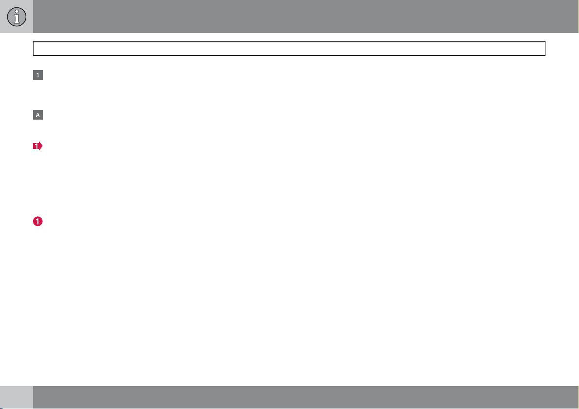
Procedure lists
Procedures where action must be taken in a
certain sequence are numbered in the owner's
manual.
9
Page 11
Introduction
Important information
When there is a series of illustrations for
step-by-step instructions each step is
numbered in the same way as the corresponding illustration.
There are numbered lists with letters adjacent to the series of illustrations where the
order of the instructions is not significant.
Arrows appear numbered and unnumbered and are used to illustrate a movement.
If there is no series of illustrations for step-bystep instructions then the different steps are
numbered with normal numbers.
Position lists
Red circles containing a number are used
in overview images where different components are pointed out. The number
recurs in the position list featured in connection with the illustration that describes
the item.
Bulleted lists
A bulleted list is used when there is a list of
points in the owner's manual.
Example:
Coolant
•
Engine oil
•
To be continued
`` This symbol is located furthest down to the
right when a section continues on the next
double-page spread.
Recording data
One or more of the computers in your Volvo are
capable of recording detailed information. This
information is intended for use in research to
enhance safety and for diagnosing faults in
some of the in-car systems. The data may
include details regarding seatbelt use by the
driver and passengers, the functions of various
vehicle systems and modules, and status information about the engine, throttle, steering,
brakes and other systems. This data can also
include details of the way the car is driven. This
type of information can include, without being
limited to, specific details such as vehicle
speed, the use of the brake and accelerator
pedals and steering wheel position. This latter
type of data can be stored for a limited period
while the car is being driven and subsequently
during a collision or a near-collision. Volvo Car
Corporation will not disclose the stored information without consent. However, Volvo Car
Corporation may be forced to disclose the
information due to national legislation. Volvo
Car Corporation and its authorised workshops
may also read and use the information.
Accessories and extra equipment
The incorrect connection and installation of
accessories can negatively affect the car's
electrical system. Certain accessories only
function when their associated software is
installed in the car's computer system. Always
contact an authorised Volvo workshop before
installing accessories which are connected to
or affect the electrical system.
Information on the Internet
At www.volvocars.com there is further information concerning your car.
10
Page 12
Volvo Cars' environmental philosophy
Introduction
Volvo and the environment
G000000
Environmental care is one of Volvo Car Corporation's core values which influence all operations. We also believe that our customers share
our consideration for the environment.
Your Volvo complies with strict international
environmental standards and is also manufactured in one of the cleanest and most resourceefficient plants in the world. Volvo Car Corporation has global ISO certification, which
includes the environmental standard ISO
14001 covering all factories and several of our
other units. We also set requirements for our
partners so that they work systematically with
environmental issues.
EPI (Environmental Product Information) is
supplied for all Volvo models. Here you can see
how the environment is affected during the
entire lifecycle of the car.
Read more at www.volvocars.com/EPI.
Fuel consumption
Volvo cars have competitive fuel consumption
in each of their respective classes. Lower fuel
consumption generally results in lower emission of the greenhouse gas, carbon dioxide.
It is possible for the driver to influence fuel consumption. For more information read under the
heading, Reducing environmental impact.
* Option/accessory, for more information, see Introduction.
Efficient emission control
Your Volvo is manufactured following the concept "Clean inside and out" – a concept that
encompasses a clean interior environment as
well as highly efficient emission control. In
many cases the exhaust emissions are well
below the applicable standards.
Clean air in the passenger compartment
A passenger compartment filter prevents dust
and pollen from entering the passenger compartment via the air intake.
A sophisticated air quality system, IAQS* (Interior Air Quality System) ensures that the incom-
11
Page 13
Introduction
Volvo and the environment
ing air is cleaner than the air in the traffic
outside.
The system consists of an electronic sensor
and a carbon filter. The incoming air is monitored continuously and if there is an increase
in the level of certain unhealthy gases such as
carbon monoxide then the air intake is closed.
Such a situation may arise in heavy traffic,
queues and tunnels for example.
The entry of nitrous oxides, ground-level ozone
and hydrocarbons is prevented by the carbon
filter.
Textile standard
The interior of a Volvo is designed to be pleasant and comfortable, even for people with
contact allergies and for asthma sufferers.
Extreme attention has been given to choosing
environmentally-compatible materials. This
means that they also fulfil the requirements in
the Oeko-Tex 100 standard
towards a healthier passenger compartment
environment.
Oeko-Tex certification covers seatbelts, carpets and fabrics for example. The leather in the
upholstery undergoes chromium-free tanning
with plant substances and fulfils the certification requirements.
1
, a major advance
Volvo workshops and the environment
Regular maintenance creates the conditions
for a long service life and low fuel consumption
for your car. In this way you contribute to a
cleaner environment. When Volvo's workshops
are entrusted with the service and maintenance of your car it becomes part of our system. We make clear demands regarding the
way in which our workshops are designed in
order to prevent spills and discharges into the
environment. Our workshop staff have the
knowledge and the tools required to guarantee
good environmental care.
Reducing environmental impact
You can easily help reduce environmental
impact, for example, by driving economically
and by servicing and maintaining the car
according to the instructions in the owner's
manual.
The following advice will help you to do your bit
for the environment: (for further advice on how
you can reduce environmental impact and
drive economically, see page 130).
Decrease fuel consumption by choosing
•
ECO tyre pressure, see page 174.
A roof load and ski box increase air resis-
•
tance, leading to higher fuel consumption.
Remove them directly after use.
Remove unnecessary items from the car.
•
The greater the load the higher the fuel
consumption.
If the car is equipped with an engine block
•
heater, always use it before starting from
cold. This reduces fuel consumption and
exhaust emissions.
Drive gently and avoid braking too hard.
•
Drive in the highest gear possible. Low
•
engine speeds result in lower fuel consumption.
Use engine braking to slow down.
•
Avoid letting the engine idle. Pay attention
•
to local regulations. Switch off the engine
when stationary for longer periods.
Always dispose of environmentally hazar-
•
dous waste, such as batteries and oils, in
an environmentally safe manner. If uncertain about disposal, consult an authorised
Volvo workshop for advice.
Service your car regularly.
•
High speed increases consumption con-
•
siderably due to increased wind resistance. A doubling of speed increases wind
resistance 4 times.
These hints will help reduce fuel consumption
without increasing travel time or lessening the
enjoyment of driving. Apart from being kind to
1
More information on www.oekotex.com
12
Page 14
your car, you'll be saving money - and the
Earth's resources.
Introduction
Volvo and the environment
13
Page 15

Seatbelts................................................................................................. 16
Airbag system......................................................................................... 19
Airbags (SRS).......................................................................................... 20
Activating/deactivating the airbag (SRS)*............................................... 23
Side airbags (SIPS bags)........................................................................ 25
Inflatable Curtain (IC)............................................................................... 27
WHIPS..................................................................................................... 28
When the systems deploy....................................................................... 30
Crash mode............................................................................................. 31
Child safety............................................................................................. 32
14
* Option/accessory, for more information, see Introduction.
G020871
Page 16
SAFETY
01
Page 17
01 Safety
01
Seatbelts
General information
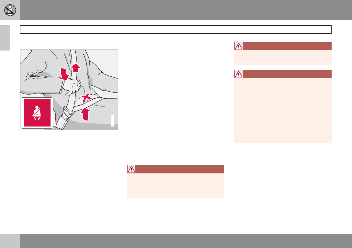
Tensioning the hip strap. The belt must be positioned low down.
Heavy braking can have serious consequences
if the seatbelts are not used. Ensure that all
passengers use their seatbelts. It is important
that the seatbelt lies against the body so it can
provide maximum protection. Do not lean the
backrest too far back. The seatbelt is designed
to protect in a normal seating position.
Putting on a seatbelt
±
Pull the seatbelt out slowly and secure it by
pressing the buckle into the lock. A loud
"click" indicates that the seatbelt has
locked.
Releasing the seatbelt
±
Press the red lock button and then let the
seatbelt retract. If the seatbelt does not
retract fully, feed the seatbelt in by hand so
that it does not hang loose.
The seatbelt locks and cannot be withdrawn:
if it is pulled out too quickly.
•
during braking and acceleration.
•
if the car leans heavily.
•
Keep in mind the following:
do not use clips or anything else that can
•
G020104
prevent the seatbelt from fitting properly
ensure that the seatbelt is not twisted or
•
caught on anything
the hip strap must be positioned low down
•
(not over the abdomen)
tension the hip strap over the lap by pulling
•
the diagonal shoulder belt as illustrated.
WARNING
The seatbelts and airbags interact. If a seatbelt is not used or is used incorrectly, this
may diminish the protection provided by the
airbag in the event of a collision.
WARNING
Each seatbelt is designed for only one person.
WARNING
Never modify or repair the seatbelt yourself.
Contact an authorised Volvo workshop. If
the seatbelt has been subjected to a major
load, such as in a collision, the entire seatbelt must be replaced. Some of the seatbelt's protective properties may have been
lost even if the seatbelt does not appear
damaged. The seatbelt must also be
replaced if it shows signs of wear or damage. The new seatbelt must be typeapproved and designed for installation at
the same location as the replaced seatbelt.
16
Page 18
01 Safety
Seatbelts and pregnancy
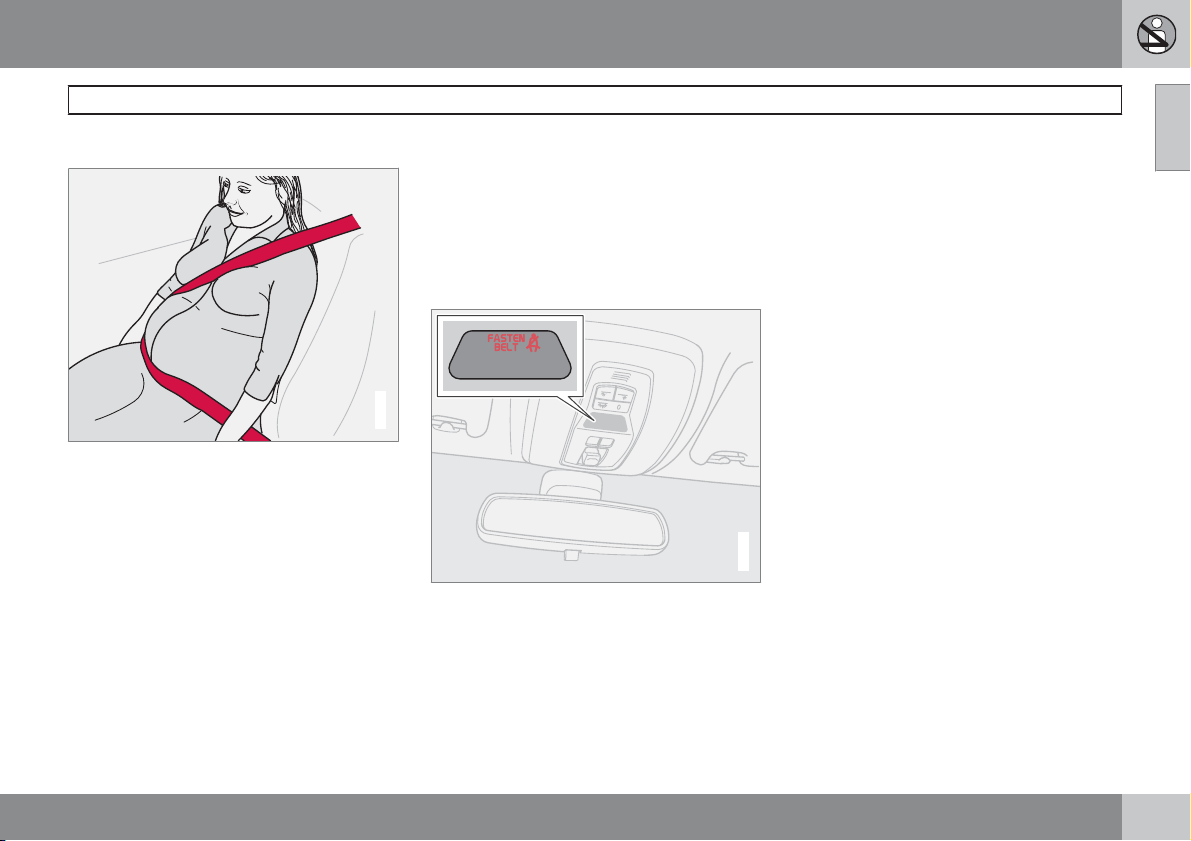
The seatbelt should always be worn during
pregnancy. But it is crucial that it be worn in the
correct way. The diagonal section of the seatbelt should wrap over the shoulder then be
routed between the breasts and to the side of
the abdomen. The lap section of the seatbelt
should lay flat over the thighs and as low as
possible under the abdomen. – It must never
be allowed to ride upward. Remove all slack
from the seatbelt and ensure that it fits close to
the body. In addition, check that there are no
twists in the seatbelt.
As a pregnancy progresses, pregnant drivers
should adjust their seats and steering wheel
such that they can easily maintain control of the
vehicle as they drive (which means that they
must be able to easily operate the foot pedals
and steering wheel). They should strive to position the seat with as large a distance as possible between their abdomen and the steering
wheel.
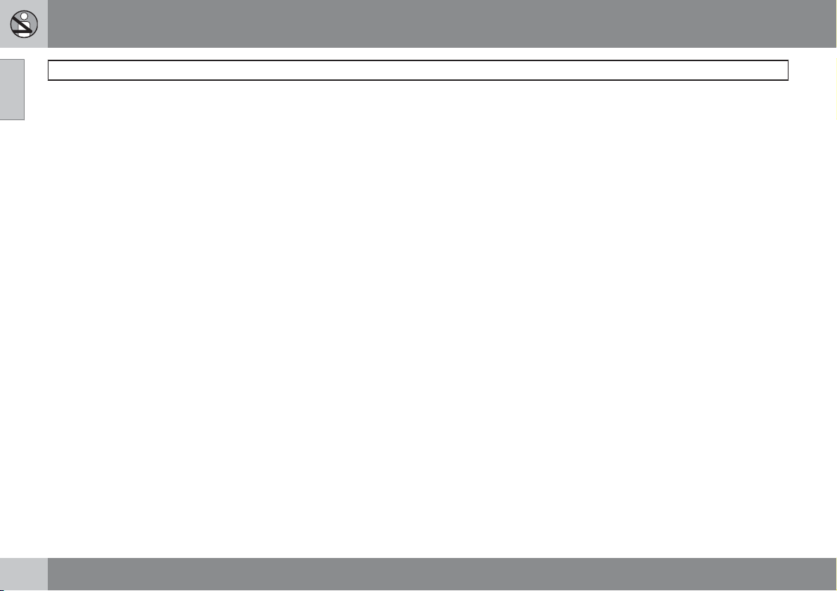
Seatbelt reminder
G020105
Unbelted occupants will be reminded to fasten
their seatbelts by means of an audio and visual
reminder. The audio reminder is speed
dependent, and in some cases time dependent. The visual reminder is located in the roof
console and the combined instrument panel.
Child seats are not covered by the seatbelt
reminder system.
Rear seat
The seatbelt reminder in the rear seat has two
subfunctions:
Provides information on which seatbelts
•
are being used in the rear seat. A message
is shown in the information display when
the seatbelts are used or the rear doors are
opened. The message is automatically
cleared after approx. 30 seconds or can be
acknowledged manually by pressing the
READ button.
Provides a warning if one of the rear seat-
•
belts is unfastened during a journey. This
warning takes the form of a message on
the information display along with the
audio/visual signal. The warning ceases
when the seatbelt is re-fastened or when
acknowledged manually by pressing the
READ button.
The message on the information display showing which seatbelts are in use is always avail-
G018084
able. Press the READ button to see stored
messages.
Certain markets
An audio signal and indicator lamp remind the
driver if not wearing a seatbelt to use one. At
low speed, the audio reminder will sound for
the first six seconds.
Seatbelts
01
``
17
Page 19
01 Safety
01
Seatbelts
Seatbelt tensioner
All the seatbelts are equipped with seatbelt
tensioners. A mechanism in the seatbelt tensioner tightens the seatbelt in the event of a
sufficiently violent collision. The seatbelt then
provides more effective restraint for occupants.
18
Page 20
01 Safety
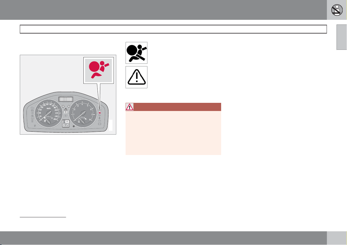
Warning symbol on the combined
instrument panel
The airbag system 1 is continually monitored by
the system's control module. The warning
symbol in the combined instrument panel illuminates when the ignition key is turned to position I, II or III. The symbol goes out after
approx. 6 seconds provided the airbag sys-
1
tem
is working correctly.
As well as the warning symbol, a
message may appear on the display in appropriate cases. If the
warning symbol malfunctions, the
warning triangle illuminates and
the message SRS AIRBAG
SERVICE REQUIRED
AIRBAG SERVICE URGENT
appears in the display. Contact an
authorised Volvo workshop immediately.
WARNING
If the warning symbol for the airbag system
remains illuminated or illuminates while driving, it means that the airbag system does
G029041
not have full functionality. The symbol indicates a fault in the seatbelt tensioner system, SIPS, SRS system or IC system.
Contact an authorised Volvo workshop
urgently.
or SRS
Airbag system
01
1
Includes SRS and seatbelt tensioner, SIPS and IC.
19
Page 21
01 Safety
01
Airbags (SRS)
Airbag system
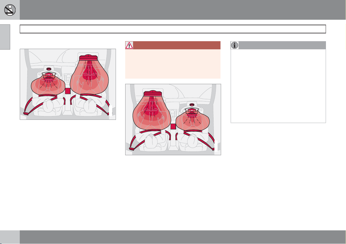
SRS system, left-hand drive
The system consists of airbags and sensors. A
sufficiently violent collision trips the sensors
and the airbag(s) are inflated with hot gas. To
cushion the impact, the airbag deflates when
compressed. When this occurs, smoke
escapes into the car. This is completely normal. The entire process, including inflation and
deflation of the airbag, takes place within
tenths of a second.
WARNING
Repairs must only be performed by an
authorised Volvo workshop. Any interference in the airbag system could cause malfunction and result in serious personal
injury.
G020111
SRS system, right-hand drive
NOTE
The sensors react differently depending on
the course of the collision and whether or
not the seatbelts on the driver's side and
passenger side are used.
It is therefore possible that only one (or
none) of the airbags may inflate in a collision. The airbag system senses the force of
the collision on the car and adapts accordingly so that one or more airbags is
deployed.
The capacities of the airbags are also adapted to the collision force to which they are
subjected.
G020110
20
Page 22
01 Safety
G020109
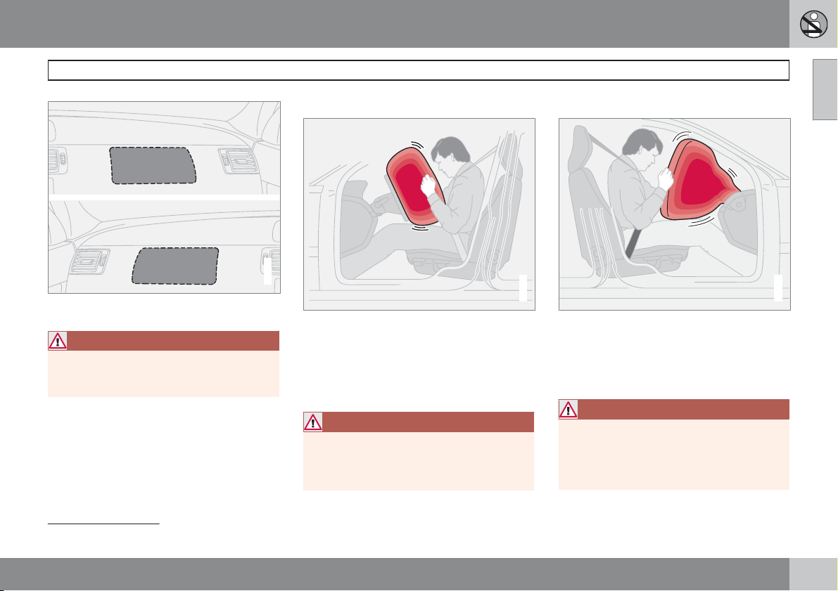
Location of the passenger airbag in left-hand drive
and right-hand drive cars
WARNING
Do not put objects in front of or above the
instrument panel where the passenger airbag is located.
Airbag (SRS) on the driver's side
G020113
The car has an SRS airbag (Supplemental
Restraint System) in the steering wheel to supplement the protection afforded by the seatbelt
on the driver's side. This airbag is folded up
into the centre of the steering wheel. The steering wheel is marked SRS AIRBAG.
WARNING
The seatbelts and airbags interact. If a seatbelt is not used or is used incorrectly, this
may diminish the protection provided by the
airbag in the event of a collision.
Airbags (SRS)
Passenger airbag (SRS)
G020108
The car has an airbag 1 to supplement the protection afforded by the seatbelt on the passenger side. This airbag is folded up into a
compartment above the glovebox. Its cover
panel is marked SRS AIRBAG.
WARNING
To minimise the risk of injury if the airbag
deploys, passengers must sit as upright as
possible with their feet on the floor and back
against the backrest. Seatbelts must be
secured.
01
1
Not all cars have a passenger airbag (SRS). This can be unselected when the car is ordered.
``
21
Page 23
01 Safety
01
Airbags (SRS)
WARNING
Never place a child in a child seat or on a
booster cushion in the front seat if the airbag
(SRS) is activated.
Never allow a child to stand or sit in front of
the front passenger seat. No one shorter
than 140 cm should ever sit in the front passenger seat if the airbag (SRS) is activated.
Failure to follow the advice given above can
endanger the life of the child.
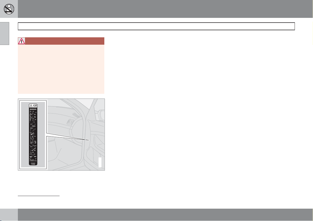
Location of decal for front passenger airbag.
2
G032243
2
For information on activated/deactivated airbag (SRS) see page 23.
22
Page 24
01 Safety
G019800
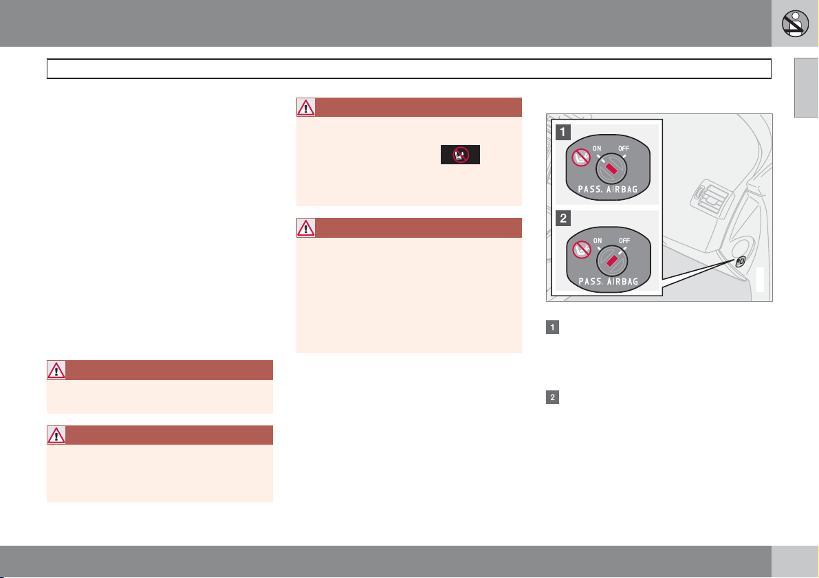
Key switch off - PACOS
General information
The airbag (SRS) for the front passenger seat
can be deactivated if the car is equipped with
a PACOS switch. For information on how to
activate/deactivate, see under the heading
Activating/deactivating.
Key switch off/switch
The switch for the passenger airbag (PACOS)
is located on the passenger end of the instrument panel and is accessible when the passenger door is open, (see under the heading,
Switch – PACOS). Check that the switch is in
the required position. Volvo recommends that
the key blade is used to change position.
For information on the key blade, see
page 113.
WARNING
Failure to follow the advice given above can
endanger life.
WARNING
If the car is equipped with a front passenger
airbag (SRS), but does not have a switch
(PACOS), the airbag will always be activated.
Activating/deactivating the airbag (SRS)*
WARNING
Never place a child in a child seat or on a
booster cushion in the front seat if the airbag
is activated and the symbol
roof console is illuminated. Failure to follow
this advice could endanger the life of the
child.
WARNING
Do not allow anyone to sit in the front passenger seat if the text message in the roof
panel indicates that the airbag (SRS) is
deactivated and if the warning symbol for
the airbag system is also displayed on the
combined instrument panel. This indicates
that there has been a severe malfunction.
Contact an authorised Volvo workshop
immediately.
in the
01
Activating/deactivating
Switch location.
The airbag is activated. With the switch in
this position, persons taller than 140 cm
can sit in the front passenger seat, but
never children in a child seat or on a
booster cushion.
The airbag is deactivated. With the switch
in this position, children in a child seat or
on a booster cushion can sit in the front
passenger seat, but never persons taller
than 140 cm.
* Option/accessory, for more information, see Introduction.
``
23
Page 25
01 Safety
01
Activating/deactivating the airbag (SRS)*
WARNING
Activated airbag (passenger seat):
Never place a child in a child seat or on a
booster cushion on the front passenger seat
when the airbag is activated. This applies to
everyone shorter than 140 cm.
Deactivated airbag (passenger seat):
No one taller than 140 cm should ever sit in
the front passenger seat when the airbag is
deactivated.
Failure to follow the advice given above can
endanger life.
Messages
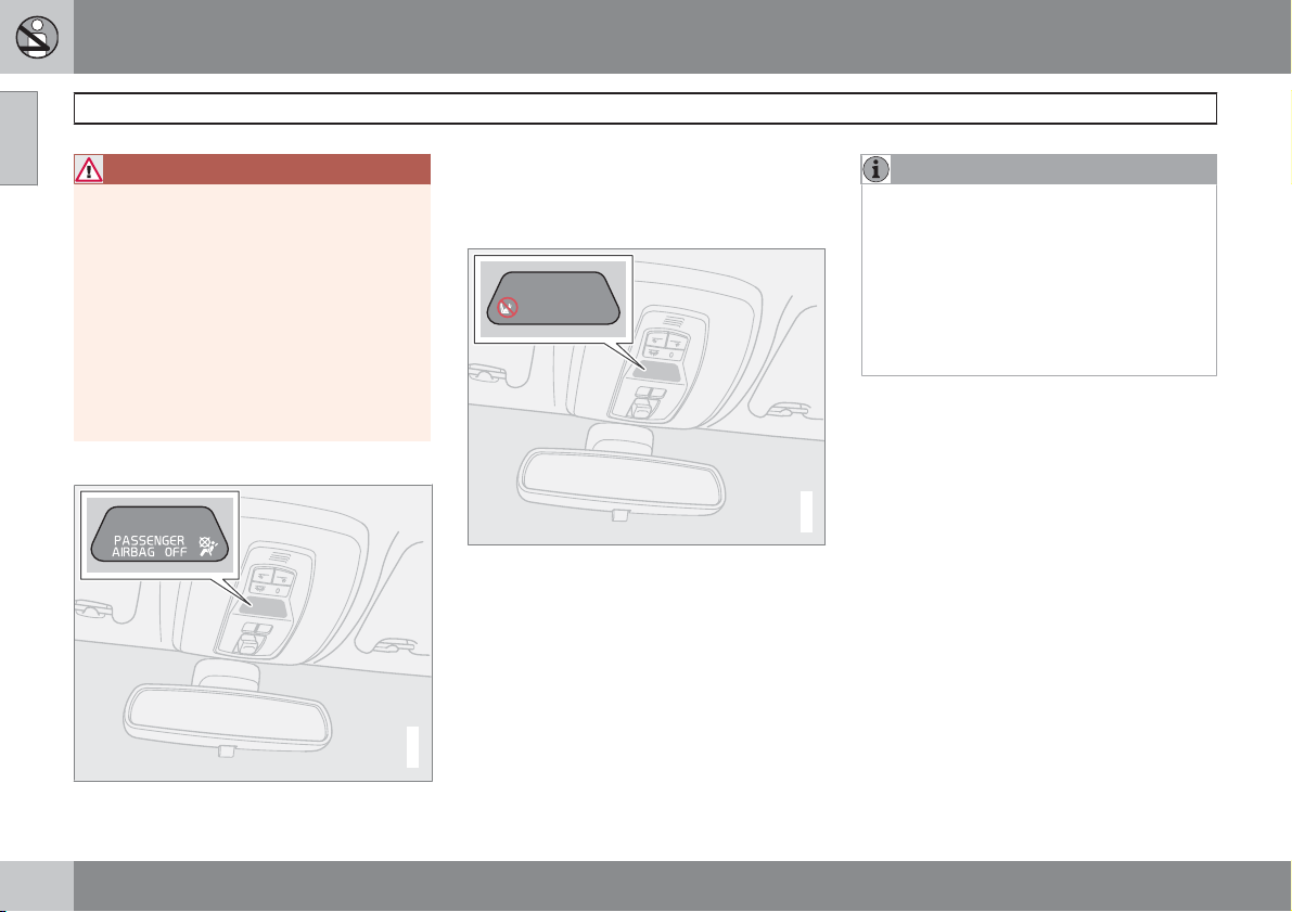
2
A text message and a symbol in the roof panel
indicate that the airbag (SRS) for the front passenger seat is deactivated (see preceding illustration).
Indicator showing that the passenger airbag (SRS)
is activated.
A warning symbol in the roof panel indicates
that the airbag (SRS) for the front passenger
seat is activated (see preceding illustration).
NOTE
When the remote control is turned to ignition
position II or III the warning symbol for the
airbag is shown in the combined instrument
panel for approx. 6 seconds, see page 19.
Following which, the indicator in the roof
console is illuminated showing the correct
status for the front passenger seat airbag.
For more information on the different ignition positions, see page 133.
G018083
Indicator showing that the passenger airbag (SRS)
is deactivated.
24
* Option/accessory, for more information, see Introduction.
G018082
Page 26
01 Safety
G025315
Side airbags – SIPS bags
Side airbag locations.
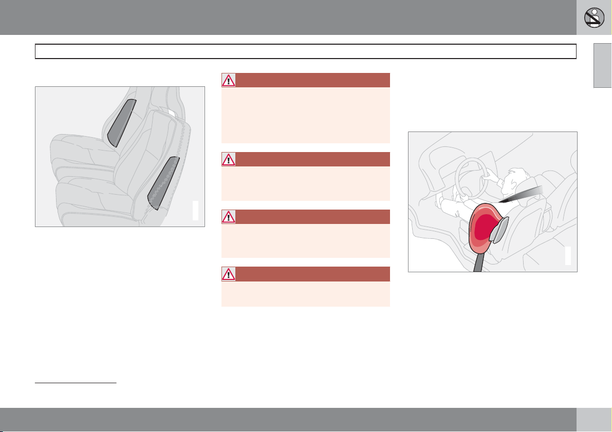
In a side impact collision a large proportion of
the collision force is transferred by the SIPS
(Side Impact Protection System) to beams, pillars, the floor, the roof and other structural
parts of the body. The side airbags at the driver's and front passenger seats protect the
chest area and are an important part of the
SIPS. The side airbags are located in the front
seat backrests.
WARNING
Repairs must only be performed by an
authorised Volvo workshop.
Any interference in the SIPS bag system
could cause malfunction and result in serious personal injury.
WARNING
Do not put objects in the area between the
outside of the seat and the door panel, since
this area is required by the side airbag.
G020118
WARNING
Only use car seat covers approved by
Volvo. Other seat covers may impede the
operation of the side airbags.
WARNING
Side airbags are a supplement the seatbelts. Always use a seatbelt.
Child seats and side airbags
The protection provided by the car to children
seated in a child seat or on a booster cushion
is not diminished by the side airbag.
Side airbags (SIPS bags)
A child seat or booster cushion can be placed
on the front passenger seat provided that the
car does not have an activated
airbag.
SIPS bags
Driver's seat, left-hand drive.
The SIPS bag system consists of side airbags
and sensors. A sufficiently violent collision trips
the sensors and the side airbags are inflated.
The airbag inflates between the occupant and
the door panel and thereby cushions the initial
impact. The airbag deflates when compressed
by the collision. The side airbag is normally only
deployed on the side of the collision.
1
passenger
01
1
For information on activated/deactivated airbag (SRS), see page 23.
``
25
Page 27
01 Safety
01
Side airbags (SIPS bags)
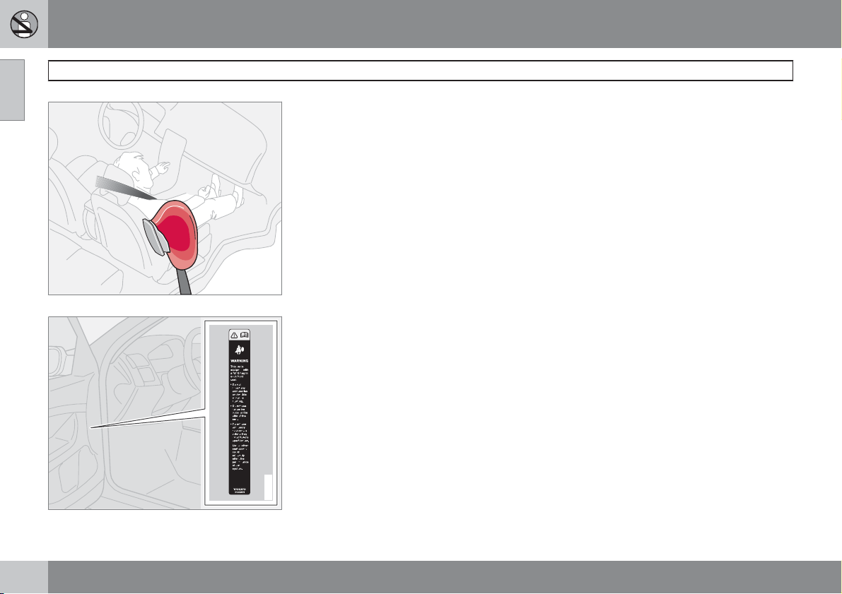
Front passenger seat, left-hand drive.
G025316
Location of decal for side airbag, driver's side,
front, left-hand drive car.
26
G032246
Page 28
01 Safety
Properties
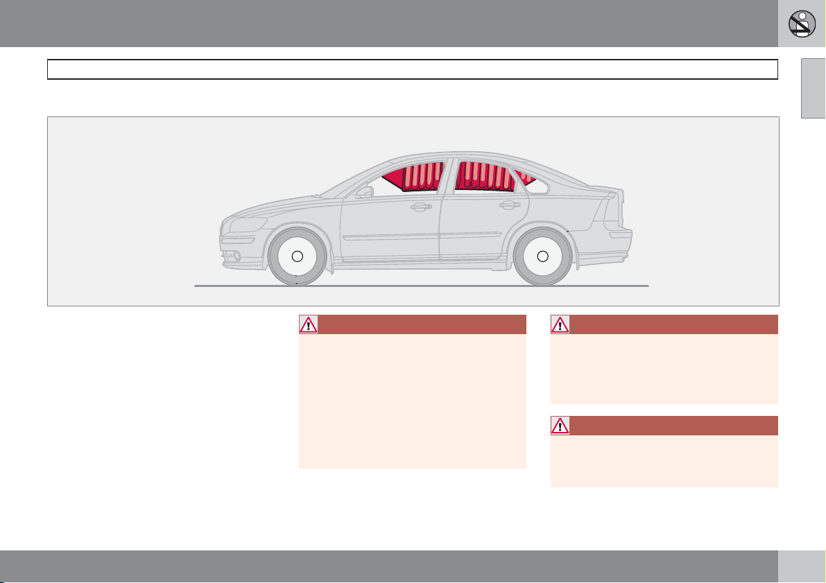
The inflatable curtain IC (Inflatable Curtain) is a
supplement to the SIPS and the airbags. It is
fitted in the headlining along both sides of the
roof and protects all of the vehicle's outer
seats. A sufficiently violent collision trips the
sensors and the inflatable curtain is inflated.
The inflatable curtain helps to prevent the
driver and passengers from striking their heads
on the inside of the car during a collision.
WARNING
Never hang or attach heavy items onto the
handles in the roof. The hook is only
designed for light clothing (not for solid
objects such as umbrellas for example).
Do not screw or install anything onto the
car's headlining, door pillars or side panels.
This could compromise the intended protection. Only ever use Volvo genuine parts
that are approved for placement in these
areas.
Inflatable Curtain (IC)
WARNING
Do not load the car higher than 50 mm under
the top edge of the side windows. Otherwise, the intended protection of the inflatable curtain, which is concealed in the
headlining, may be compromised.
WARNING
The inflatable curtain is a supplement to the
seatbelts.
Always use a seatbelt.
01
G015265
27
Page 29
01 Safety
01
WHIPS
Protection against whiplash injury – WHIPS
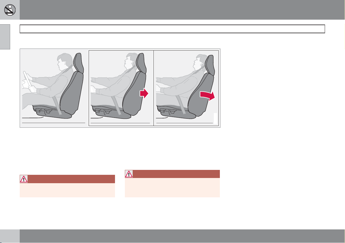
The whiplash protection system (WHIPS) consists of energy absorbing backrests and specially designed head restraints for the front
seats. The system is actuated by a rear-end
collision, where the angle and speed of the collision, and the nature of the colliding vehicle all
have an influence.
WARNING
The WHIPS system is a supplement to the
seatbelts. Always use a seatbelt.
Properties of the seat
When the WHIPS system is deployed, the front
seat backrests are lowered backward to alter
the seating position of the driver and front seat
passenger. This reduces the risk of whiplash
injury.
WARNING
Never modify or repair the seat or WHIPS
system yourself. Contact an authorised
Volvo workshop.
G020347
WHIPS system and child seats/booster
cushions
The protection provided by the car to children
seated in a child seat or on a booster cushion
is not diminished by the WHIPS system.
Correct seating position
For the best possible protection, the driver and
front seat passenger should sit in the centre of
the seat with as little space as possible
between the head and the head restraint.
28
Page 30
01 Safety
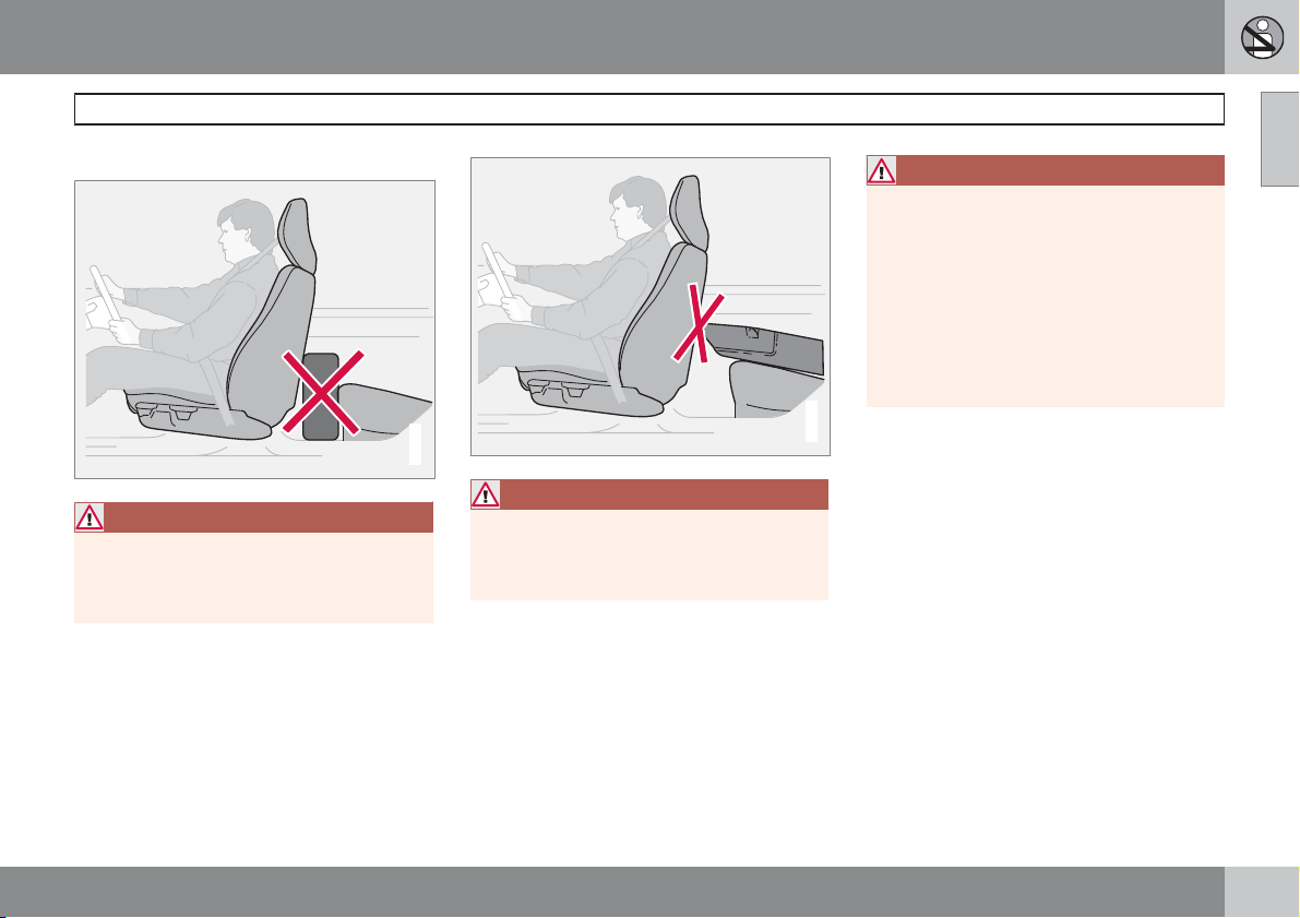
Do not obstruct the WHIPS system
WARNING
Do not squeeze rigid objects between the
rear seat cushion and the front seat backrest. Make sure you do not to obstruct the
function of the WHIPS system.
G020125
WARNING
If a rear seat backrest is folded down, the
corresponding front seat must be moved
forward so that it does not touch the folded
backrest.
WARNING
If a seat has been subjected to extreme
forces, such as due to a rear-end collision,
the WHIPS system must be checked by an
authorised Volvo workshop.
Part of the WHIPS system's protective
capacity may have been lost even if the seat
appears to be undamaged.
Contact an authorised Volvo workshop to
have the system checked after even a minor
rear-end collision.
G020126
WHIPS
01
29
Page 31
01 Safety
01
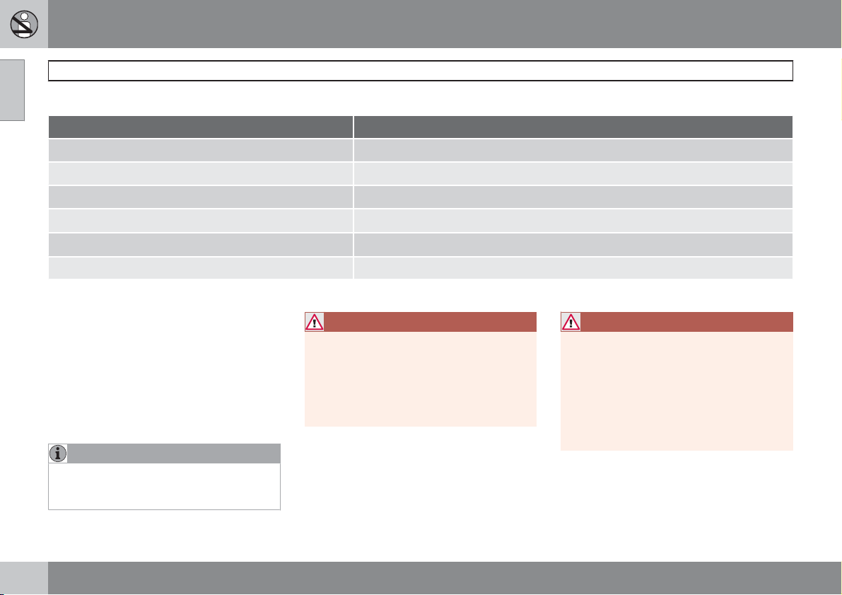
When the systems deploy
Activating the systems
System Triggered
Seatbelt tensioner, front seat In a frontal collision and/or side-impact accident and/or rear-end collision.
Seatbelt tensioner, outside rear seat In a frontal collision
Airbags (SRS)
Side airbags (SIPS)
Inflatable Curtain IC
Whiplash protection WHIPS In a rear-end collision
A
The bodywork of the car could be greatly deformed in a collision without airbag deployment. A number of factors such as the rigidity and weight of the object hit, the speed of the car, the angle of
the collision etc. affects how the different safety systems of the car are activated.
If the airbags have been deployed, the following is recommended:
Have the car transported to an authorised
•
Volvo workshop. Do not drive with
deployed airbags.
Let an authorised Volvo workshop replace
•
components in the car's safety system.
Always contact a doctor.
•
NOTE
The SRS, SIPS, IC and belt tensioner systems are deployed only once during a collision.
In a frontal collision
In a side-impact accident
In a side-impact accident
A
A
A
WARNING
The airbag system's control module is
located in the centre console. If the centre
console is drenched with water or other liquid, disconnect the battery cables. Do not
attempt to start the car since the airbags
may deploy. Have the car transported to an
authorised Volvo workshop.
WARNING
Never drive with deployed airbags. They
can make steering difficult. Other safety
systems may also be damaged. The smoke
and dust created when the airbags are
deployed can cause skin and eye irritation/
injury after intensive exposure. In case of
irritation, wash with cold water. The rapid
deployment sequence and airbag fabric
may cause friction and skin burns.
30
Page 32
01 Safety
Driving after a collision
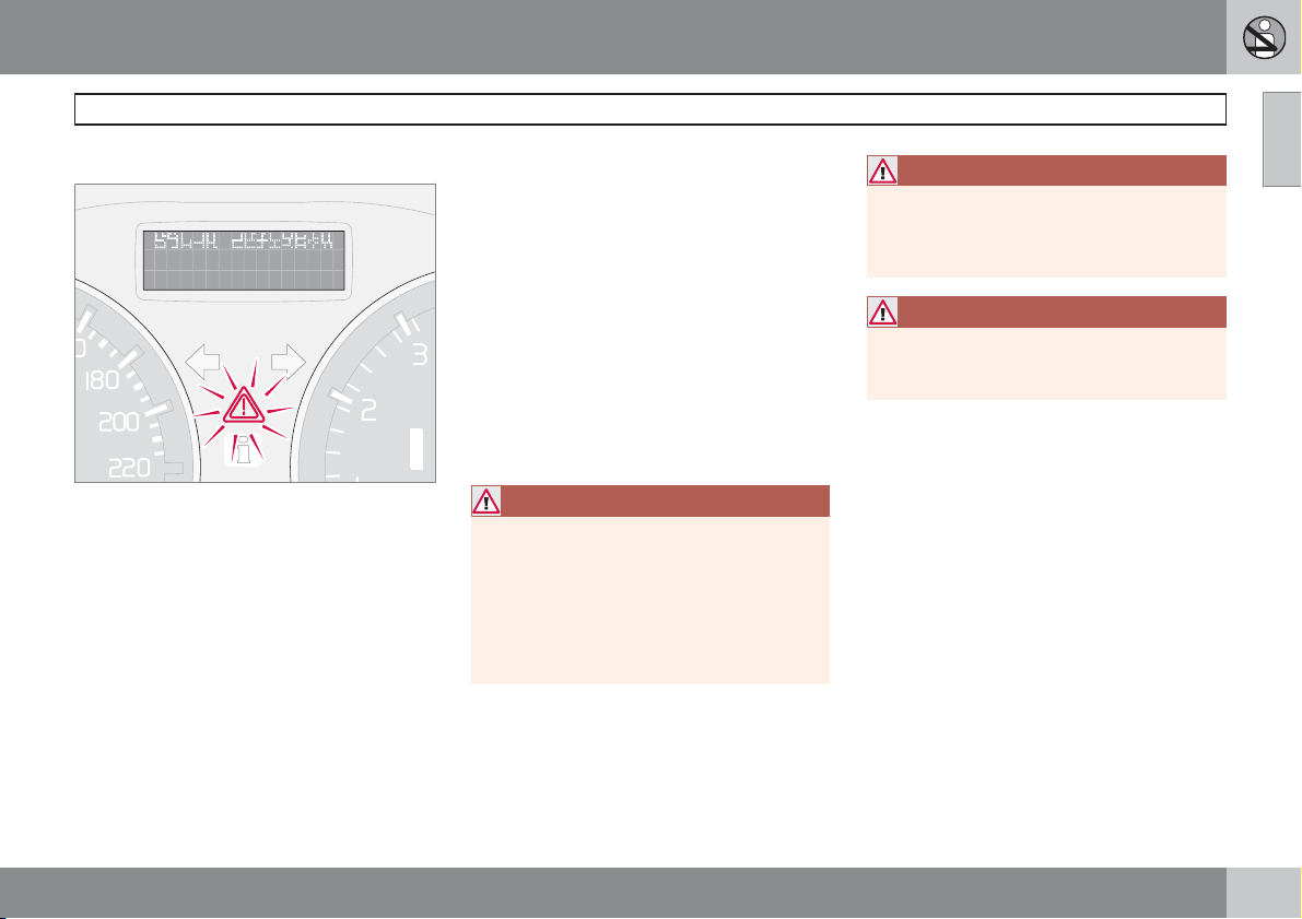
If the car is involved in a collision, the text
CRASH MODE SEE MANUAL may appear on
the information display. This means that the car
has reduced functionality. Crash mode is a
protective state that is enforced when the collision may have damaged any of the car's vital
functions, such as the fuel lines, sensors for
one of the safety systems, or the brake system.
Attempting to start the car
First, check that no fuel is leaking from the car.
There must be no smell of fuel either.
If everything seems normal and you have
checked for indications of fuel leakage, you
may attempt to start the car.
Firstly, remove the ignition key and then reinsert it. The car's electronics will then try to reset
themselves to normal mode. Then try to start
the car. If CRASH MODE SEE MANUAL is
still shown on the display then the car must not
be driven or towed. Even if the car appears to
be driveable, hidden damage may make the
car impossible to control once moving.
Moving the car
If NORMAL MODE is shown after CRASH
MODE SEE MANUAL
can be moved carefully out of a dangerous
position. Do not move the car further than necessary.
G029042
has been reset, the car
WARNING
Never attempt to repair your car or reset the
electronics yourself if the car has been in
crash mode. This could result in personal
injury or the car not functioning as normal.
Always allow an authorised Volvo workshop
to check and restore the car to
MODE
after CRASH MODE SEE
MANUAL
has been displayed.
NORMAL
Crash mode
WARNING
Never, under any circumstances, attempt to
restart the car if it smells of fuel when the
CRASH MODE SEE MANUAL message is
displayed. Leave the car at once.
WARNING
If the car is in crash mode it must not be
towed. It must be transported to an authorised Volvo workshop.
01
31
Page 33
01 Safety
01
Child safety
Children should sit comfortably and
safely
The position of a child in the car and the choice
of equipment are dictated by the child's weight
and size. For more information, see
page 33.
NOTE
Regulations regarding the placement of
children in cars vary from country to country. Check what does apply.
Children of all ages and sizes must always sit
correctly secured in the car. Never allow a child
to sit on the knee of a passenger.
Volvo's own child safety equipment is
designed for your car. Use Volvo genuine
equipment to best ensure that the mounting
points and attachments are correctly positioned and are sufficiently strong.
NOTE
In the event of questions when fitting child
safety products, contact the manufacturer
for clearer instructions.
Child seats
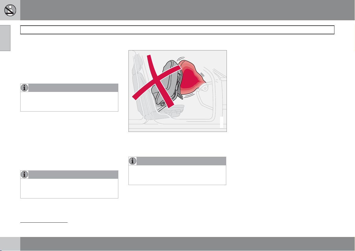
Child seats and airbags are not compatible.
Volvo has child safety products that are
designed for and tested by Volvo.
NOTE
When using child safety products it is
important to read the installation instructions included with the product.
Do not attach the straps for the child seat to
the horizontal adjustment bar, springs, rails or
beams under the seat. Sharp edges can damage the straps.
Allow the back of the child seat to rest against
the dashboard. This applies to cars without a
passenger airbag, or where the airbag is deactivated.
Location of child seats
You may place:
a child seat/booster cushion on the front
•
passenger seat, provided the passenger
airbag is not activated 1.
a rear-facing child seat in the rear seat that
•
G020128
uses the back of the front seat as support.
Always place a child in the rear seat if the passenger airbag is activated. A child in the front
passenger seat could suffer serious injury if the
airbag deploys.
1
For information on activated/deactivated airbag (SRS), see page 23.
32
Page 34
01 Safety
WARNING
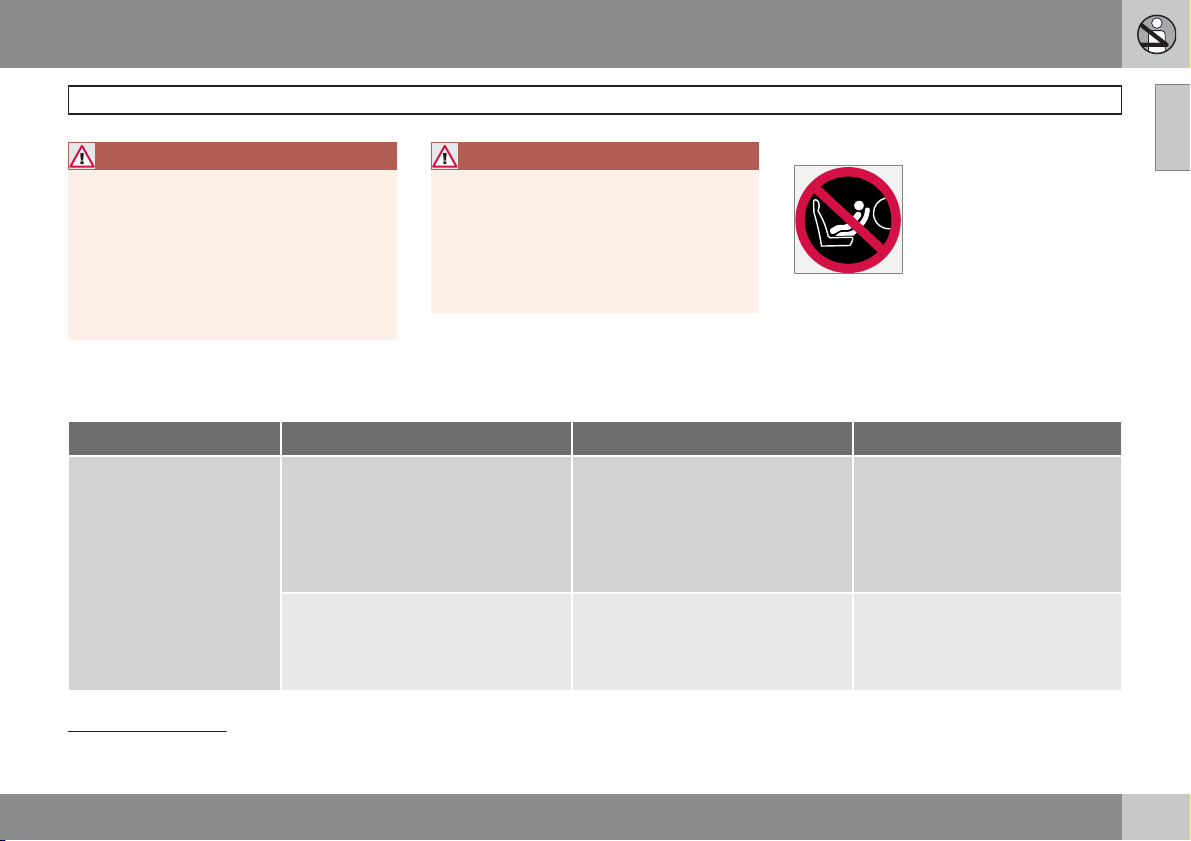
Never place a child in a child seat or on a
booster cushion in the front seat if the airbag
(SRS) is activated.
No one shorter than 140 cm should ever sit
in the front passenger seat if the airbag
(SRS) is activated.
Failure to follow the advice given above can
endanger the life of the child.
2
Placement of children in the car
Weight/age
Group 0
max. 10 kg
(0 – 9 months)
Group 0+
max. 13 kg
Front seat
Volvo Child seat – rear-facing child
seat, secured with the car's seatbelt
and straps. Use a protective cushion
between the child seat and the dashboard.
Type approval: E5 03135
Britax Baby Safe Plus – rear-facing
child seat, secured with the ISOFIX fixture system.
Type approval: E1 03301146
Child safety
WARNING
Booster cushions/child seats with steel
braces or some other design that could rest
on the seatbelt buckle's opening button
must not be used, as they could cause the
seatbelt buckle to open accidentally.
Do not allow the upper section of the child
seat to rest against the windscreen.
3
A
Outer rear seat Centre rear seat
Volvo Child seat – rear-facing child
seat, secured with the car's seatbelt,
straps and support legs.
Type approval: E5 03135
Britax Baby Safe Plus – rear-facing
child seat, secured with the ISOFIX
fixture system.
Type approval: E1 03301146
Label Airbag
Label located on instrument panel end face.
Volvo Child seat – rear-facing child
seat, secured with the car's seatbelt, straps and support legs.
Type approval: E5 03135
Britax Baby Safe Plus – rear-facing
child seat secured with the car's
seatbelt.
Type approval: E1 03301146
01
2
For information on activated/deactivated airbag (SRS) see page 23.
3
With regard to other child seats the car should be included in the manufacturer's enclosed list of vehicles or be universally approved in accordance with the ECE R44 legal requirement.
``
33
Page 35
01 Safety
01
Child safety
Weight/age
Group 1
9 – 18 kg
(9 – 36 months)
Group 2/3
15 – 36 kg
(3 – 12 years)
A
For information on activated/deactivated airbag (SRS), see page 23.
Front seat
Volvo Child seat – rear-facing child
seat, secured with the car's seatbelt
and straps. Use a protective cushion
between the child seat and the dashboard.
Type approval: E5 03135
Britax Fixway – rear-facing child seat,
secured with the ISOFIX fixture system
and straps.
Type approval: E5 03171
Volvo Booster cushion – with or without backrest.
Type approval: E5 03139
A
Outer rear seat Centre rear seat
Volvo Child seat – rear-facing child
seat, secured with the car's seatbelt,
straps and support legs.
Type approval: E5 03135
Britax Fixway – rear-facing child seat,
secured with the ISOFIX fixture system and straps.
Type approval: E5 03171
Volvo Booster cushion – with or without backrest.
Type approval: E5 03139
Volvo Integrated booster cushion –
available as a factory fitted option.
Type approval: E5 03168
Volvo Child seat – rear-facing child
seat, secured with the car's seatbelt, straps and support legs.
Type approval: E5 03135
Volvo Booster cushion – with or
without backrest.
Type approval: E5 03139
34
* Option/accessory, for more information, see Introduction.
Page 36
01 Safety
WARNING
Never place a child in a child seat or on a
booster cushion in the front seat if the airbag
(SRS) is activated.
No one shorter than 140 cm should ever sit
in the front passenger seat if the airbag
(SRS) is activated.
Failure to follow the advice given above can
endanger the life of the child.
4
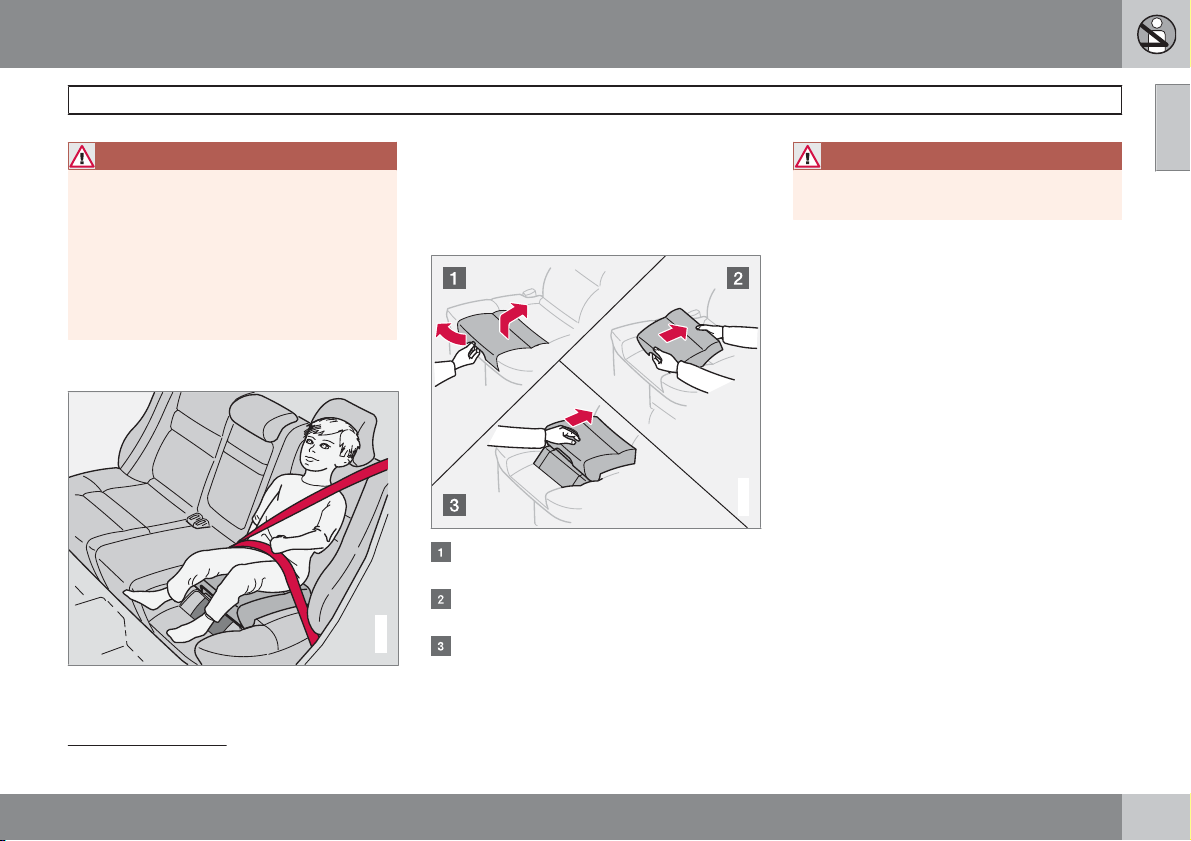
Integrated booster cushions*
vide optimum safety for children. Combined
with the regular seatbelts the integrated
booster cushion is approved for children
weighing between 15 and 36 kg.
Raising the booster cushion
Pull that handle to raise the booster cushion.
Grasp the cushion with both hands and
push it backwards.
G015013
Push until it locks in place.
WARNING
The booster cushion must be in the locked
position before the child is placed there.
Check that:
the booster cushion is locked in position.
•
the seatbelt is in contact with the child's
•
body and is not slack or twisted, and that
the seatbelt is positioned correctly across
the shoulder.
the hip strap is low across the hips for opti-
•
mum protection.
the seatbelt does not lie across the child's
•
throat or below the shoulder.
Carefully adjust the position of the head
•
restraint to suit the child.
G020808
Child safety
01
Volvo’s integrated booster cushion for the
outer rear seats is specially designed to pro-
4
For information on activated/deactivated airbag (SRS) see page 23.
``
35
Page 37
01 Safety
G015268
01
Child safety
WARNING
Repair or replacement should only be performed by an authorised Volvo workshop.
Do not make any modifications or additions
to the booster cushion.
If an integrated booster cushion has been
subjected to a major load, such as in conjunction with a collision, the entire booster
cushion must be replaced. Even if the
booster cushion appears to be undamaged,
it may not afford the same level of protection. The booster cushion must also be
replaced if it is heavily worn.
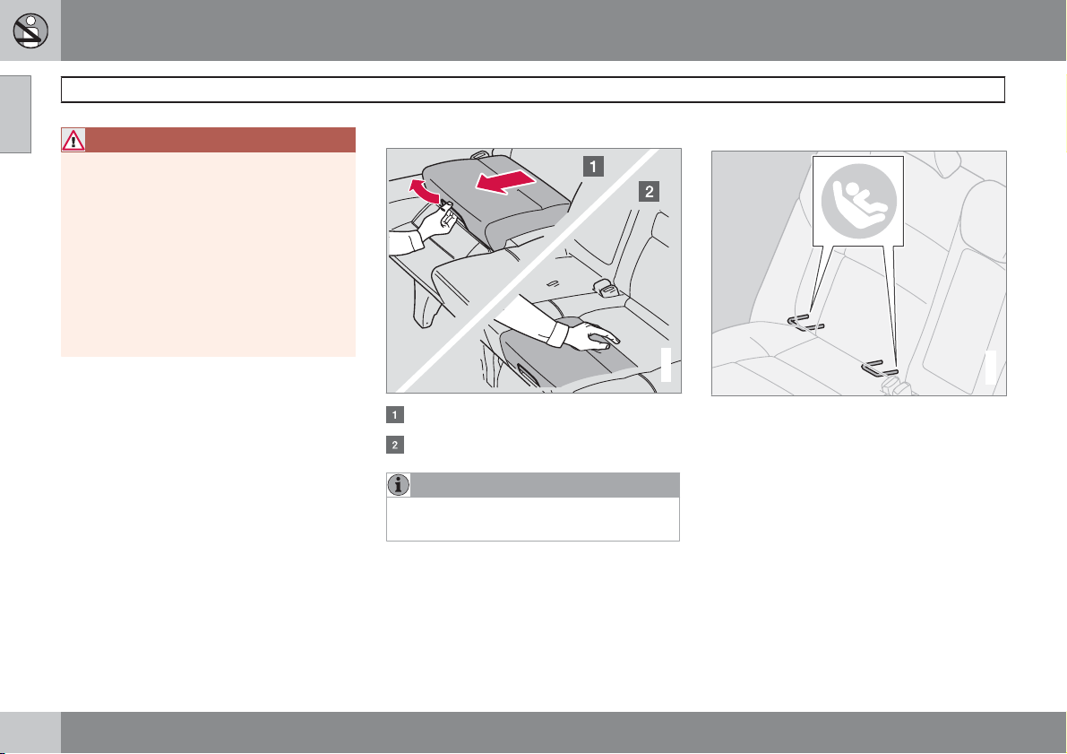
Lowering the booster cushion
Pull the handle.
Lower the seat and press until it locks.
NOTE
Remember to stow away the booster cushion before lowering the rear seat backrest.
ISOFIX fixture system for child seats*
G014507
Mounting points for the ISOFIX fixture system
are concealed behind the lower section of the
rear seat backrest, in the outer seats.
The location of the mounting points is indicated
by symbols in the backrest upholstery (see
illustration above).
Press the seat cushion down to access the
mounting points.
Always follow the manufacturer's installation
instructions when connecting a child seat to
the ISOFIX mounting points.
36
* Option/accessory, for more information, see Introduction.
Page 38
01 Safety
01
37
Page 39

Overview, left-hand drive cars................................................................ 40
Overview, right-hand drive cars.............................................................. 42
Driver's door control panel...................................................................... 44
Combined instrument panel.................................................................... 45
Indicator and warning symbols............................................................... 46
Information display.................................................................................. 50
Electrical socket...................................................................................... 52
Lighting panel.......................................................................................... 53
Left-hand stalk switch............................................................................. 56
Right-hand stalk switch.......................................................................... 59
Cruise control*........................................................................................ 61
Keypad in the steering wheel*................................................................. 63
Steering wheel adjustment, hazard warning flashers............................. 64
Parking brake.......................................................................................... 65
Power windows....................................................................................... 66
Rearview and door mirrors...................................................................... 68
Power sunroof*........................................................................................ 72
Personal preferences.............................................................................. 73
HomeLink
EU*....................................................................................... 76
G020901
38
* Option/accessory, for more information, see Introduction.
Page 40
INSTRUMENTS AND CONTROLS
02
Page 41
02
02 Instruments and controls
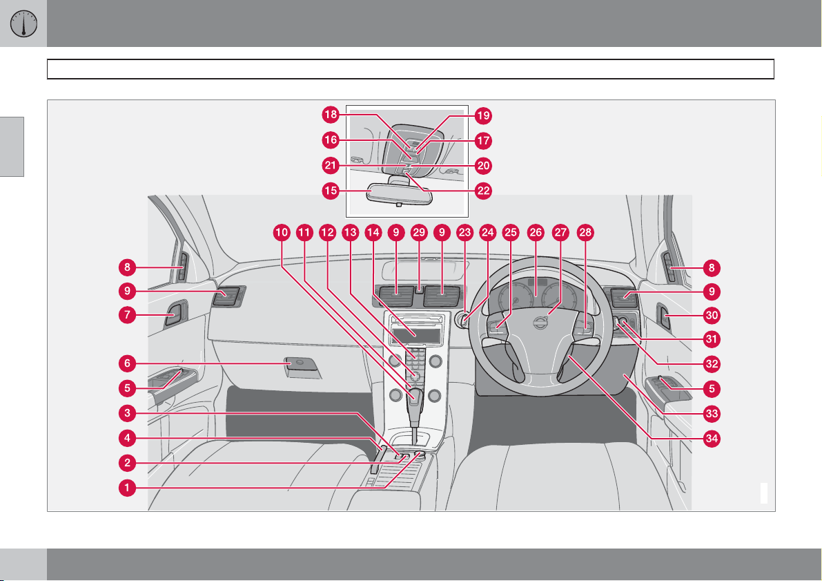
Overview, left-hand drive cars
40
G019488
Page 42
02 Instruments and controls
Overview, left-hand drive cars
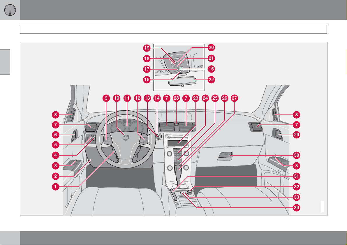
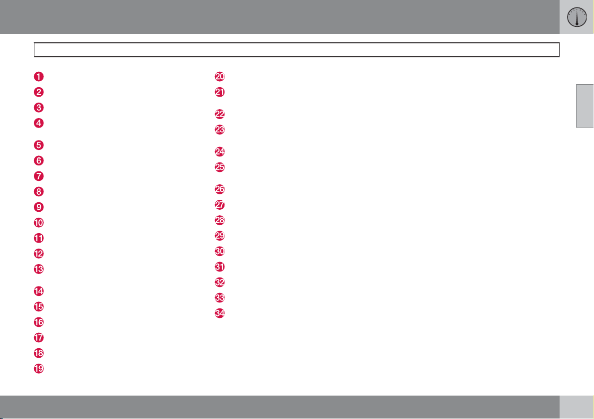
Steering wheel adjustment
Bonnet release
Control panel
Direction indicators, main beam, trip computer
Lighting, fuel filler flap opener
Door handle, lock button.
Air vents in dashboard
Air vent for side window
Cruise control
Horn, airbag
Combined instrument panel
Keypad for infotainment system
Windscreen wipers and washer, headlamp
washers
Ignition switch
Sunroof controls
No function
No function
Switch for interior lighting
Reading lamp, left-hand side
Reading lamp, right-hand side
Seatbelt reminder and passenger seat airbag indicator
Interior rearview mirror
Display for climate control and infotainment system
Infotainment system
Controls for climate control, infotainment
system and personal preferences
Climate control
Gear lever
Hazard warning flashers
Door handle
Glovebox
Parking brake
Electrical socket/cigarette lighter
Blind Spot Information System, BLIS
Switch, optional equipment
02
41
Page 43
02
02 Instruments and controls
Overview, right-hand drive cars
42
G028204
Page 44
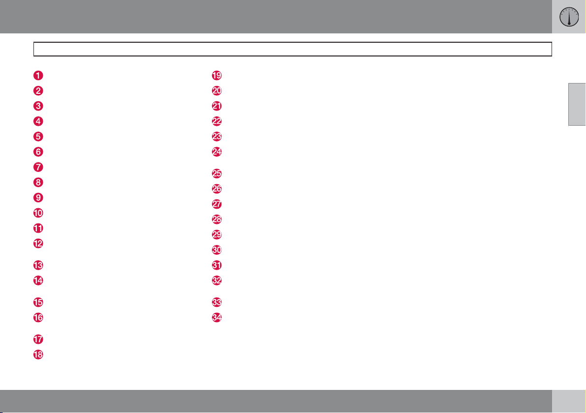
02 Instruments and controls
Overview, right-hand drive cars
Electrical socket, cigarette lighter
Blind Spot Information System, BLIS
Switch, optional equipment
Parking brake
Control panel
Glovebox
Door handle
Air vent for side window
Air vents in dashboard
Gear lever
Climate control
Controls for climate control, infotainment
system and personal preferences
Infotainment system
Display for climate control and infotainment system
Interior rearview mirror
Seatbelt reminder and passenger seat airbag indicator
Switch for interior lighting
Reading lamp, left-hand side
Reading lamp, right-hand side
No function
No function
Sunroof controls
Ignition switch
Windscreen wipers and washers, headlamp washers
Cruise control
Combined instrument panel
Horn, airbag
Keypad for infotainment system
Hazard warning flashers
Door handle, lock button
Lighting, fuel filler flap opener
Direction indicators, main beam, trip computer
Bonnet release
Steering wheel adjustment
02
43
Page 45
02 Instruments and controls
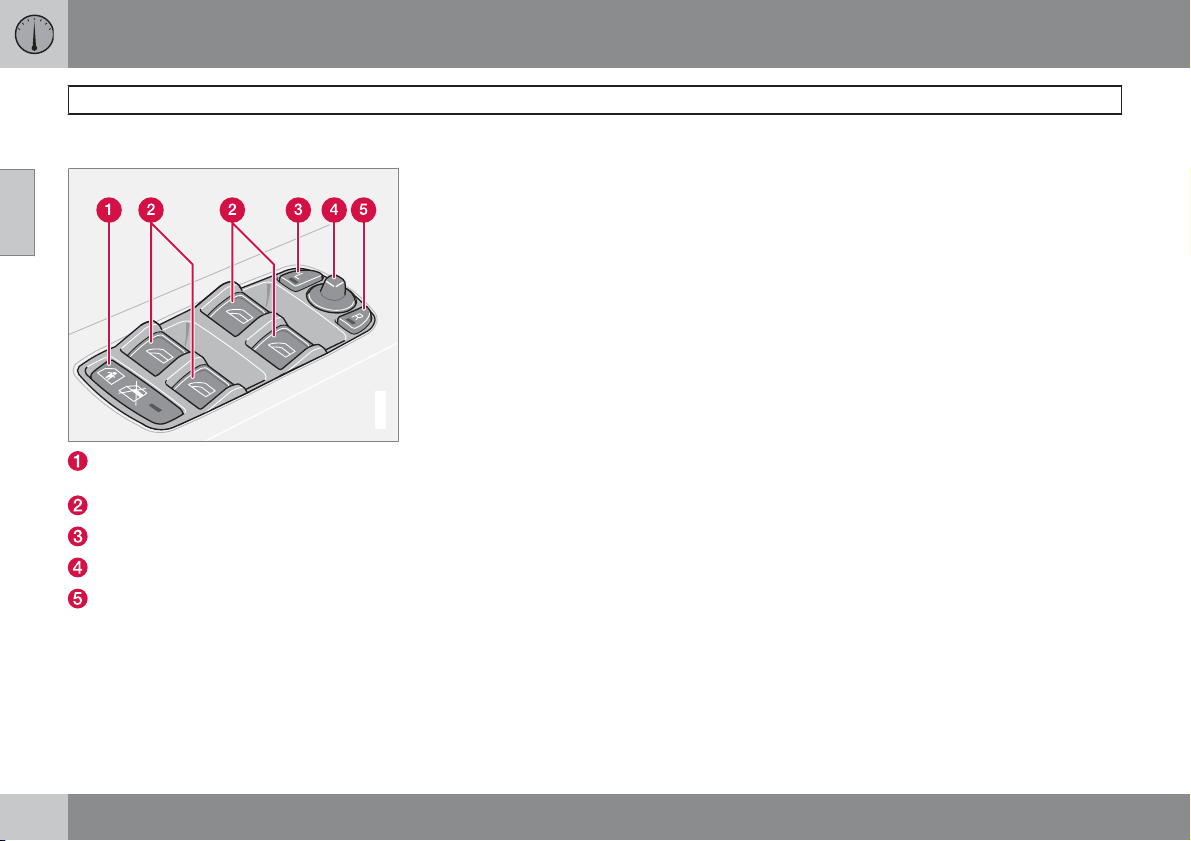
Driver's door control panel
Driver's door control panel
02
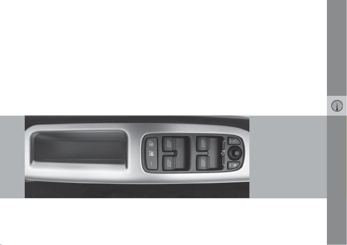
Disengaging the rear power windows.
Electric child safety lock*
Power windows
Door mirror, left-hand side
Door mirrors, setting
Door mirror, right-hand side
G017435
44
* Option/accessory, for more information, see Introduction.
Page 46
02 Instruments and controls
Combined instrument panel
02
G029046
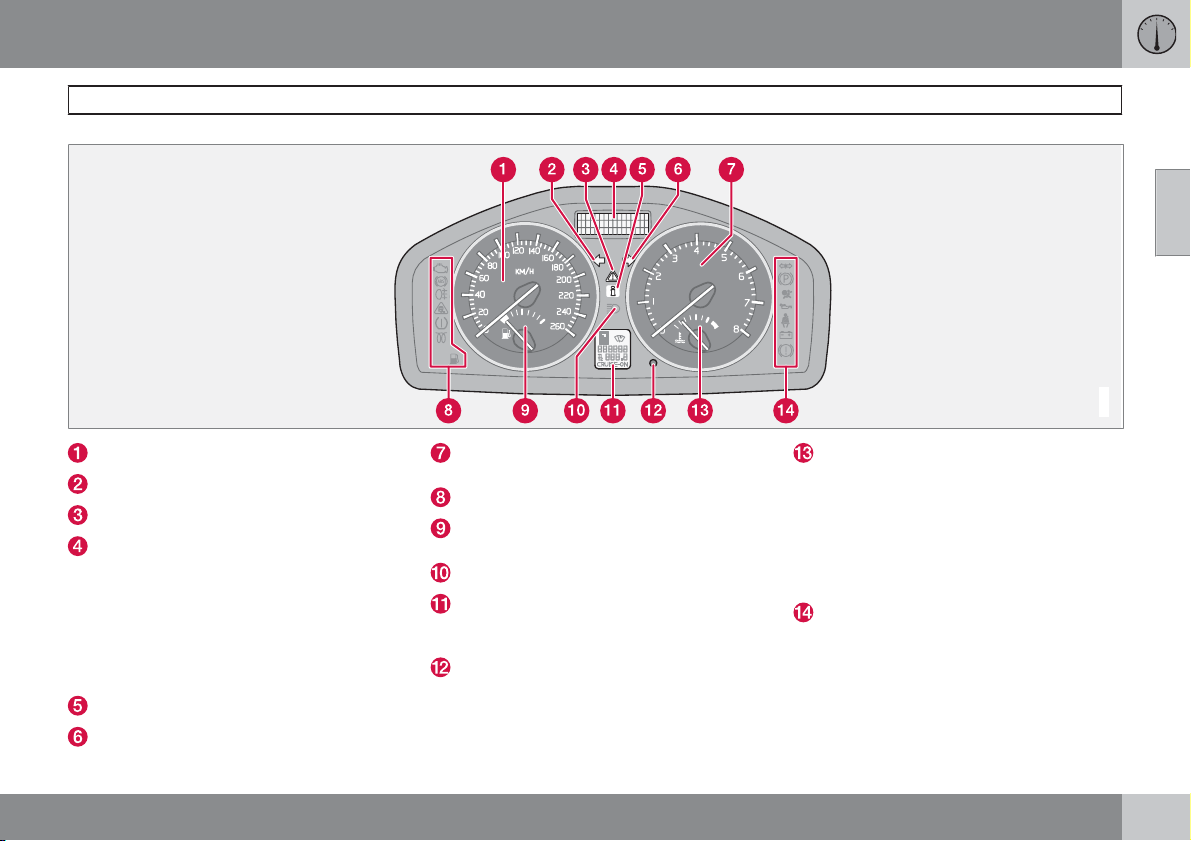
Speedometer.
Direction indicators, left.
Warning symbol.
Information display – The display presents
information or warning messages, outside
temperature and clock. When the outside
temperature is between +2 °C and -5 °C a
snowflake symbol appears on the display.
This warns of icy roads. The outside temperature gauge may show a slightly high
reading after the car has been stationary.
Information symbol.
Direction indicator, right.
Tachometer – Indicates engine speed in
thousands of revolutions per minute (rpm).
Indicator and warning symbols.
Fuel gauge, see also trip computer, page
57.
Main beam indicator.
Display – Display for automatic gear position, rain sensor, odometer, trip meter and
cruise control.
Button for trip meter – Used to measure
short distances. Short presses on the button switches between the two trip meters
T1 and T2. A long press (more than 2 sec-
onds) resets an active trip meter to zero.
Temperature gauge - Used for the engine
cooling system. A message will appear on
the display if the temperature becomes too
high and the gauge goes into the red zone.
Bear in mind that extra lights placed in front
of the air intake, for example, reduce the
cooling capacity at high outside temperatures and high engine loads.
Indicator and warning symbols.
45
Page 47
02 Instruments and controls
Indicator and warning symbols
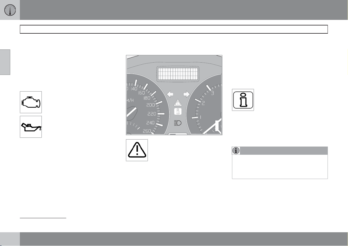
Functionality check, symbols
All indicator and warning symbols 1 illuminate
02
when the ignition key is turned to position II
before starting. This is to check that the symbols are working. When the engine starts, all
the symbols should go out except the handbrake symbol, which only goes out when the
brake is disengaged.
If the engine does not start within
five seconds, all symbols extinguish except the symbols for a
fault in the car's emissions system
and for low oil pressure. Certain
symbols may have no function,
depending on the car's specifications.
Symbols in the centre of the instrument
panel
The red warning symbol illuminates when a fault has been indicated which could affect the safety
and/or driveability of the car. An
explanatory text is shown on the
information display at the same time. The symbol remains visible until the fault has been rectified but the text message can be cleared with
the READ button, see page 50. The warning
symbol can also illuminate in conjunction with
other symbols.
When the symbol illuminates:
1. Stop in a safe manner. Do not drive the car
further.
2. Read the information on the information
display. Implement the action in accordance with the message in the display. Clear
the message using READ.
The yellow information symbol illuminates and a text appears on the
information display. The message
text is cleared using the READ but-
automatically after a period of time (time
depending on which function is indicated).
G030755
The yellow information symbol can also illuminate in conjunction with other symbols.
ton, see page 50, or disappears
NOTE
When a service message is shown, the symbol and message are cleared using the
READ button, or disappear automatically
after a time.
1
For certain engine variants, the symbol for low oil pressure is not used. Warnings are given via display text, see page 50.
46
Page 48
02 Instruments and controls
Indicator and warning symbols
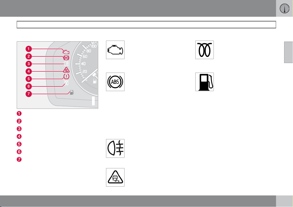
Indicator symbols – left-hand side
Fault in car's emissions system
ABS fault
Rear fog lamp
Stability system STC or DSTC
No function
Engine preheater (diesel)
Low level in fuel tank
Emissions system
If the symbol illuminates then it
may be due to a fault in the car's
emissions system. Drive to an
authorised Volvo workshop to
have the system checked.
ABS fault
If this symbol illuminates then the
system is not working. The car's
regular brake system continues to
work, but without the ABS function.
1. Stop the car in a safe place and turn off the
G029048
engine.
2. Restart the engine.
3. Drive to an authorised Volvo workshop to
have the ABS checked if the symbol
remains lit.
Rear fog lamp
This symbol is lit when the rear fog
lamp is on.
Stability system STC or DSTC*
For information on the system's
functions and symbols, see
page 147.
Engine preheater (diesel)
This symbol illuminates during
engine preheating. Preheating
occurs when the temperature is
below –2 °C. The car can be
started once the symbol goes out.
Low level in fuel tank
When the symbol illuminates the
level in the fuel tank is low, refuel
as soon as possible.
02
* Option/accessory, for more information, see Introduction.
``
47
Page 49
02 Instruments and controls
Indicator and warning symbols
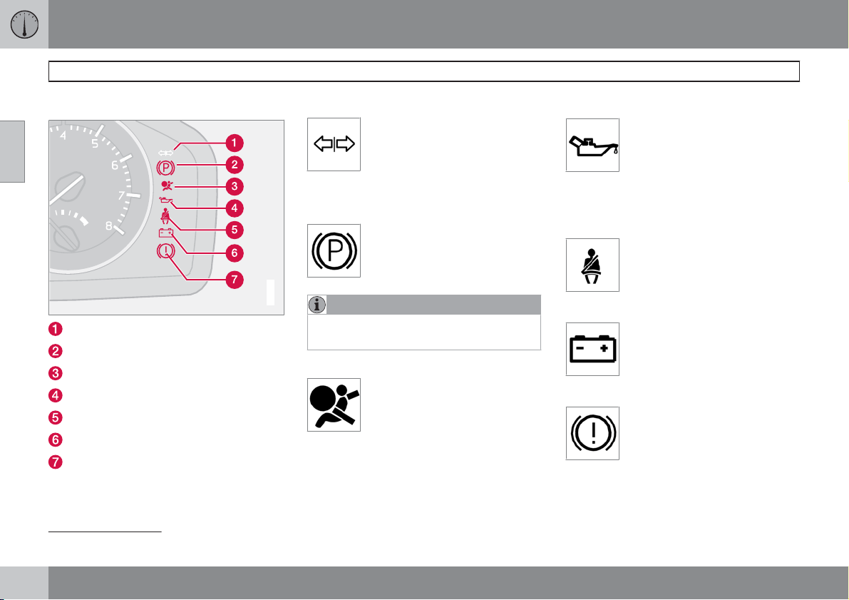
Indicator symbols – right-hand side
02
Indicator symbol for trailer
Parking brake applied
Airbags – SRS
Low oil pressure
Seatbelt reminder
Alternator not charging
Fault in brake system
Indicator symbol for trailer
This symbol flashes when the
direction indicators are used and
the trailer is connected. If the symbol does not flash then one of the
faulty.
lamps on the trailer or the car is
Parking brake applied
The symbol illuminates when the
parking brake is applied. Always
pull the parking brake lever to the
end position.
G029049
NOTE
The symbol illuminates irrespective of how
hard the parking brake is applied.
Airbags – SRS
If this symbol remains illuminated
or illuminates while driving, it
means a fault has been detected in
the seatbelt buckle, SRS, SIPS, or
authorised Volvo workshop to have the system
checked.
IC system. Drive directly to an
Low oil pressure
symbol illuminates and the oil level is normal,
contact an authorised Volvo workshop.
2
If this symbol illuminates during
driving then the engine's oil pressure is too low. Stop the engine
immediately and check the engine
oil level, top up if necessary. If the
Seatbelt reminder
This symbol illuminates if someone
in a front seat has not put on their
seatbelt or if someone in a rear
seat has taken off their seatbelt.
Alternator not charging
If this symbol illuminates while
driving, a fault has occurred in the
electrical system. Contact an
authorised Volvo workshop.
Fault in brake system
If this symbol illuminates, the brake
fluid level may be too low.
±
Stop the car in a safe place and check the
level in the brake fluid reservoir, see
page 202. If the level in the reservoir is
2
For certain engine variants, the symbol for low oil pressure is not used. Warnings are given via display text, see page 50.
48
Page 50
below MIN the car should not be driven any
further. Have the car transported to an
authorised Volvo workshop to have the
brake system checked.
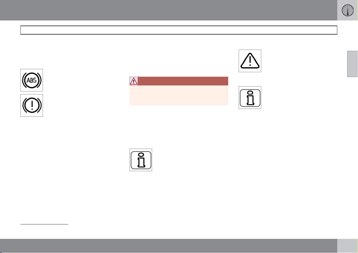
If the BRAKE and ABS symbols
illuminate at the same time, there
may be a fault in the brake force
distribution system.
1. Stop the car in a safe place and turn off the
engine.
2. Restart the engine.
3. If both symbols extinguish, continue driving.
4. If the symbols remain illuminated, check
the level in the brake fluid reservoir, see
page 202.
5. If the brake fluid level is normal but the
symbols are still lit, the car can be driven,
with great care, to an authorised Volvo
workshop to have the brake system
checked.
02 Instruments and controls
6.
If the level in the reservoir is below MIN
then the car should not be driven any further. Have the car transported to an
authorised Volvo workshop to have the
brake system checked.
WARNING
If the BRAKE and ABS symbols are lit at the
same time, there is a risk that the rear end
will skid during heavy braking.
Reminder – doors not closed
If one of the doors, the bonnet 3 or the boot lid
is not properly closed, the driver will be
reminded of this.
Low speed
DOOR OPEN, BONNET OPEN
REAR DOOR OPEN
Stop the car safely as soon as possible and
close the door or bonnet.
If the car moves at a speed less
than 5 km/h, the information symbol illuminates and
DRIVER
DOOR OPEN, PASSENGER
DOOR OPEN, LEFT REAR
is shown on the display.
or RIGHT
Indicator and warning symbols
High speed
If the car is moving faster than
10 km/h, the symbol illuminates
and one of the texts indicated in
the preceding paragraph appears
on the display.
Boot lid reminder
If the boot lid is open, this information symbol will illuminate and
BOOT LID OPEN will appear on
the display.
02
3
Only cars with alarm.
49
Page 51
02 Instruments and controls
Information display
Messages
02
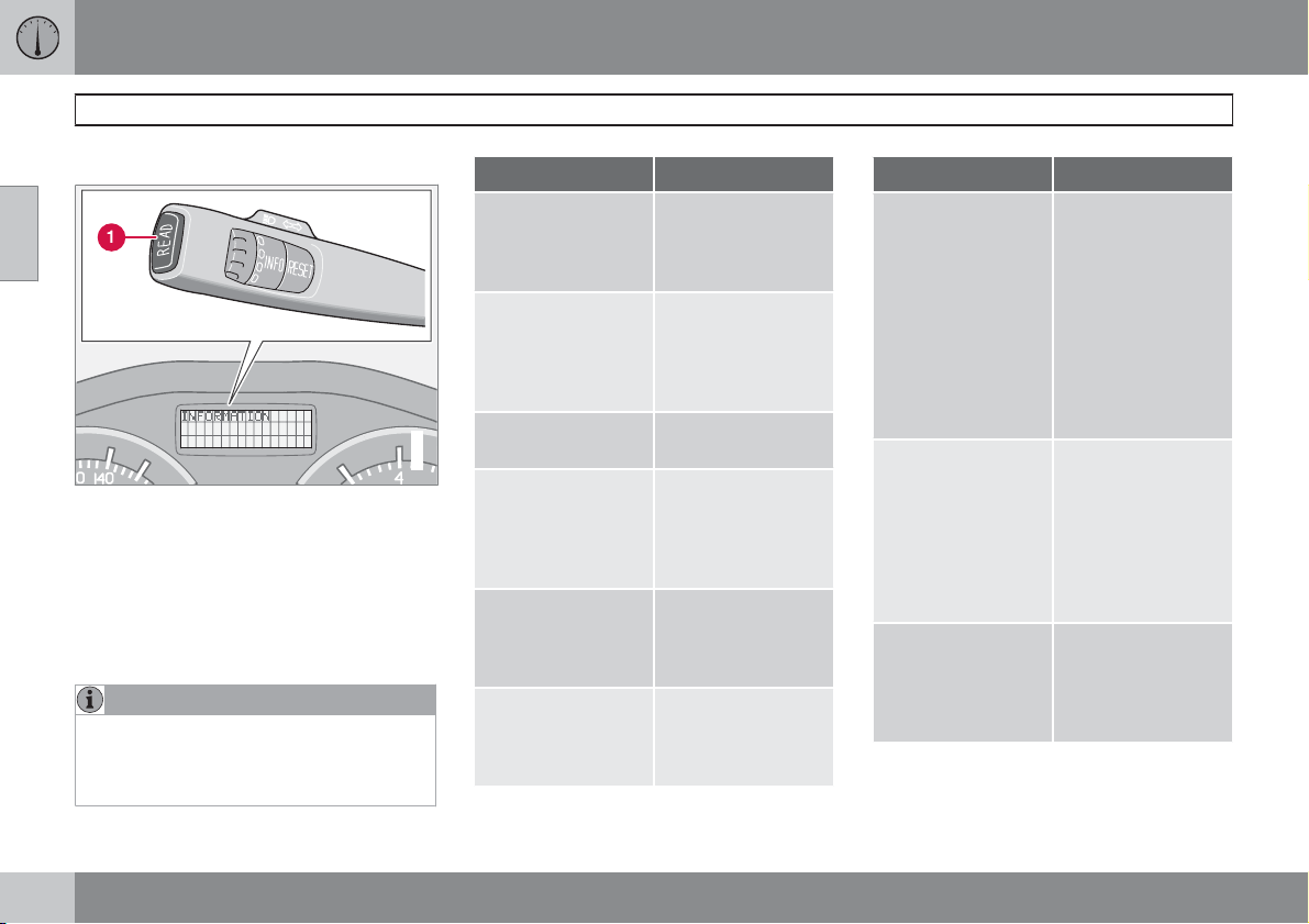
When a warning or indicator symbol illuminates
the information display shows a supplementary message.
±
Press the READ button (1).
Switch between messages with the READ button. Fault messages are stored in the memory
until the fault is rectified.
NOTE
If a warning message appears while you are
using the trip computer, the message must
be read (press READ) before the previous
activity can be resumed.
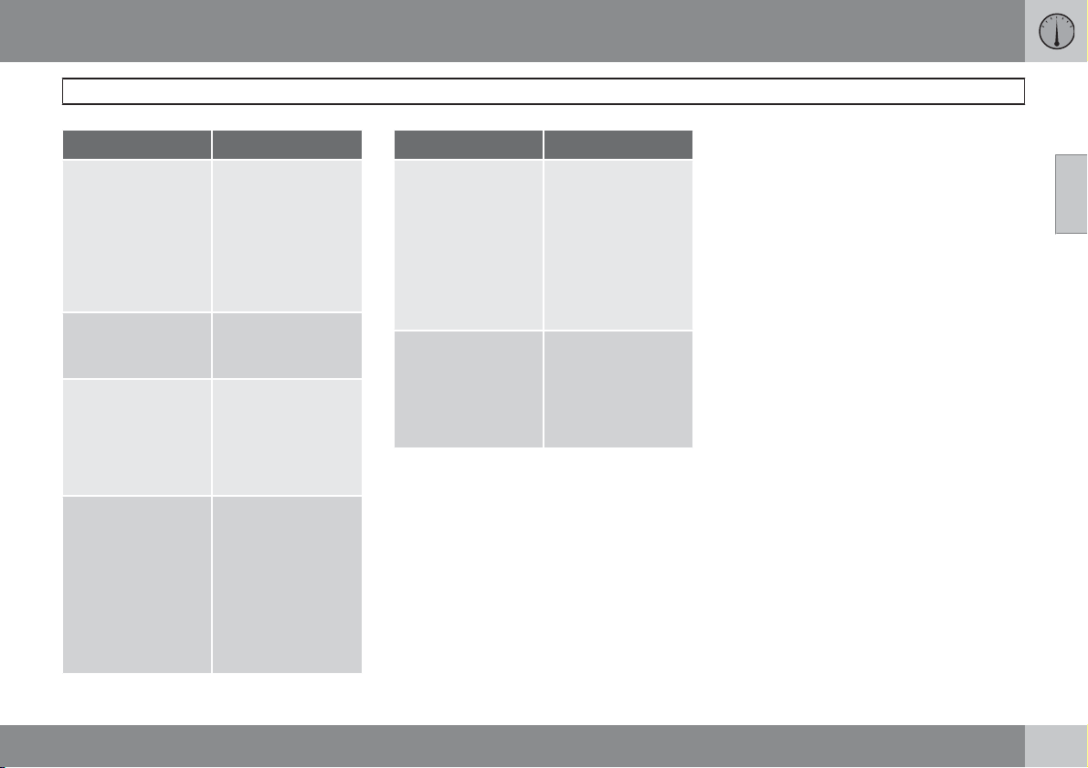
Message Specification
STOP SAFELY
SERVICE
URGENT
SEE MANUAL
G029050
SERVICE
REQUIRED
HIGH ENGINE
TEMP STOP
ENGINE
BOOK TIME FOR
SERVICE
A
A
A
A
Stop the car in a safe
manner and turn off
the engine. Serious
risk of damage.
Have the car
checked by an
authorised Volvo
workshop immediately.
Read the Owner's
Manual.
Have the car
checked by an
authorised Volvo
workshop as soon
as possible.
Stop the car in a safe
manner and turn off
the engine. Serious
risk of damage.
Time to book regular
service at an authorised Volvo workshop.
Message Specification
TIME FOR SERVICE
MAINTENANCE
OVERDUE
TRANSMISSION
OIL CHANGE NEEDED
Time for regular
service at an authorised Volvo workshop. The timing is
determined by the
number of kilometres driven, number
of months since the
last service, engine
running time and oil
grade.
If the service intervals are not followed
then the warranty
does not cover any
damaged parts.
Contact an authorised Volvo workshop for service.
Have the car
checked by an
authorised Volvo
workshop as soon
as possible.
50
Page 52
02 Instruments and controls
Information display
Message Specification
REMINDER
CHECK OIL LEVEL
SOOT FILTER
FULL SEE MANUAL
STC/DSTC SPIN
CONTROL OFF
TRANSMISSION
PERFORMANCE
LOW
Check the oil level.
The message is
shown every
10 000 km (certain
engine variants). For
information on
checking the oil
level, see page 200.
Diesel particle filter
requires regeneration, see page 272.
The function of the
stability and traction
control system is
reduced, see
page 148 for more
variants.
The gearbox cannot
handle full capacity.
Drive carefully until
the message clears,
see page 142.
If shown repeatedly:
Contact an authorised Volvo workshop.
Message Specification
TRANSMISSION
OIL TEMP HIGH
TRANSMISSION
HOT STOP
SAFELY
A
Part of message, shown together with information on where
the problem has arisen.
B
For more messages concerning automatic transmission, see
page 142.
Drive more smoothly
or stop the car in a
safe manner. Disengage the gear and
run the engine at
idling speed until the
message clears. For
more information,
see page 142.
Critical fault. Stop
the car immediately
in a safe manner.
Contact an authorised Volvo work-
B
shop.
02
51
Page 53
02 Instruments and controls
Electrical socket
12 V electrical socket
02
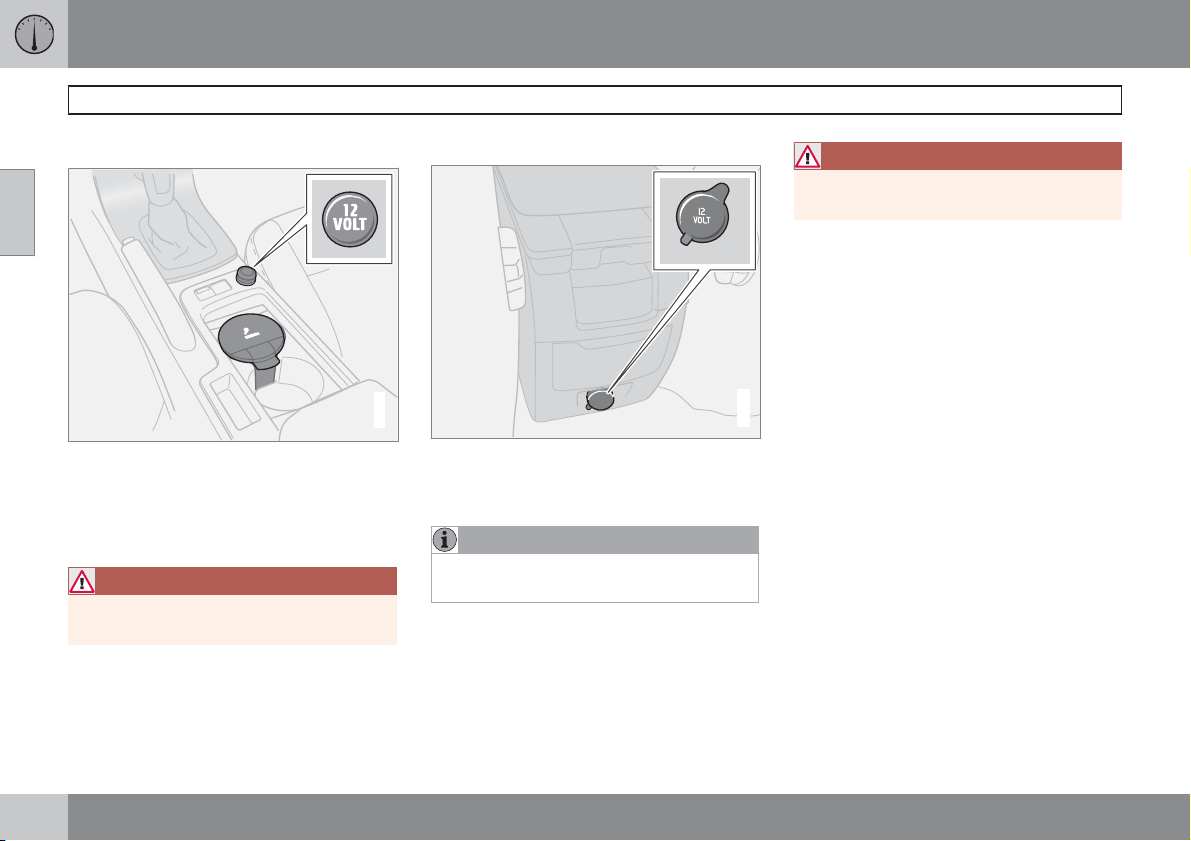
The electrical socket can be used for 12 V
accessories, such as mobile phone chargers
and coolers. The maximum current is 10 A. For
the socket to supply current, the ignition key
must be in at least position I.
WARNING
Always leave the plug in the socket when
the socket is not in use.
Cigarette lighter*
Activate the lighter by pushing in the button.
The button pops out when the lighter is hot. Pull
out the lighter and light a cigarette on the
heated coils.
Electrical socket in the rear seat
G019621
The electrical socket can be used for various
accessories, such as mobile phone chargers
and coolers.
NOTE
Cigarette lighter does not work in this
socket.
It is designed for 12 V. The maximum current
is 10 A. For the socket to supply current, the
ignition key must be in at least position I.
WARNING
Always leave the plug in the socket when it
is not in use.
G029082
52
* Option/accessory, for more information, see Introduction.
Page 54
02 Instruments and controls
Lighting panel
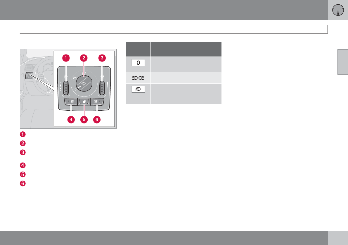
General
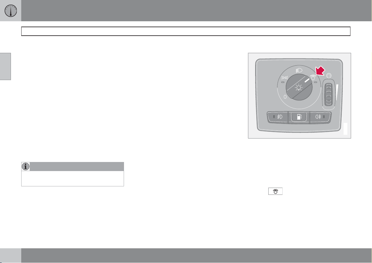
Thumbwheel for headlamp levelling
Light switches
Thumbwheel for adjusting display and
instrument lighting
Front fog lamps*
Opening the fuel filler flap
Rear fog lamp
Posi-
Specification
tion
Automatic/deactivated dipped
beam. Only main beam flash.
Position/parking lamps.
Automatic dipped beam. Main
beam and main beam flash
work in this position.
Headlamp levelling
The load in the car changes the vertical align-
G020139
ment of the headlamp beam, which could dazzle oncoming motorists. Avoid this by adjusting
the height of the beam.
1.
Turn the ignition key to position II.
2. Turn the headlamp control (2) to one of the
end positions.
3. Roll the control (1) up or down respectively
to raise or lower beam alignment.
Cars with Bi-Xenon
matic headlamp levelling, so there is no control
(1).
headlamps* have auto-
Position/parking lamps.
Position/parking lamps can be switched on
irrespective of ignition key position.
±
Turn the headlamp control (2) to the centre
position.
When the ignition key is in position II the position/parking lamps and number plate lighting
are always on.
Headlamps
Automatic dipped beam*
Dipped beam comes on automatically when
the ignition key is turned to position II, except
when the headlamp control (2) is in the centre
position. If necessary, the automatic dipped
beam can be deactivated by an authorised
Volvo workshop.
Automatic dipped beam, main beam
1.
Turn the ignition key to position II.
2. Dipped beam is activated by means of
turning the headlamp control (2) clockwise
to the end position.
3. Main beam is activated by means of moving the left-hand stalk switch towards the
steering wheel to the end position and
releasing it, see page 56.
The lamps are switched off automatically when
the ignition key is turned to position I or 0.
02
``
* Option/accessory, for more information, see Introduction.
53
Page 55
02 Instruments and controls
G026507
Lighting panel
Instrument lighting
The instrument lighting is switched on when
02
the ignition key is in position II and the headlamp control (2) is in one of the end positions.
The lighting is automatically dimmed during the
day and can be controlled manually at night.
±
Roll the control up or down (3) for brighter
or dimmer lighting.
Enhanced display lighting
To facilitate reading the odometer, trip meter,
clock and outside temperature gauge, these
illuminate when the car is unlocked and when
the key is removed from the ignition switch.
The displays extinguish when the car is locked.
Fog lamps
NOTE
Regulations for use of fog lamps vary from
country to country.
Front fog lamps*
The front fog lamps can be switched on along
with the headlamps or the position lamps/parking lamps.
±
Press the button (4).
The light in the button (4) illuminates when the
front fog lamps are switched on.
Rear fog lamp
The rear fog lamp can only be switched on with
the headlamps or the front fog lamps.
±
Press the button (6).
The rear fog lamp indicator symbol on the combined instrument panel and the light in the
button (6) illuminate when the rear fog lamp is
switched on.
Fuel filler flap
Press button (5) to open the fuel filler flap when
the car is unlocked, see page 121.
Active Bi-Xenonlights*
Lighting panel, for active Bi-Xenonlights.
If the car is equipped with active headlamps
(Active Bi-Xenon
the headlamps follows the steering wheel
movement in order to provide maximum lighting in bends and junctions and so provide
increased safety.
The LED
is activated. The LED flashes and an error message is shown on the information display in the
event of a malfunction. The function is only
active in twilight or darkness and only when the
car is moving.
Lights, ABL) the light from
illuminates when the function
54
* Option/accessory, for more information, see Introduction.
Page 56
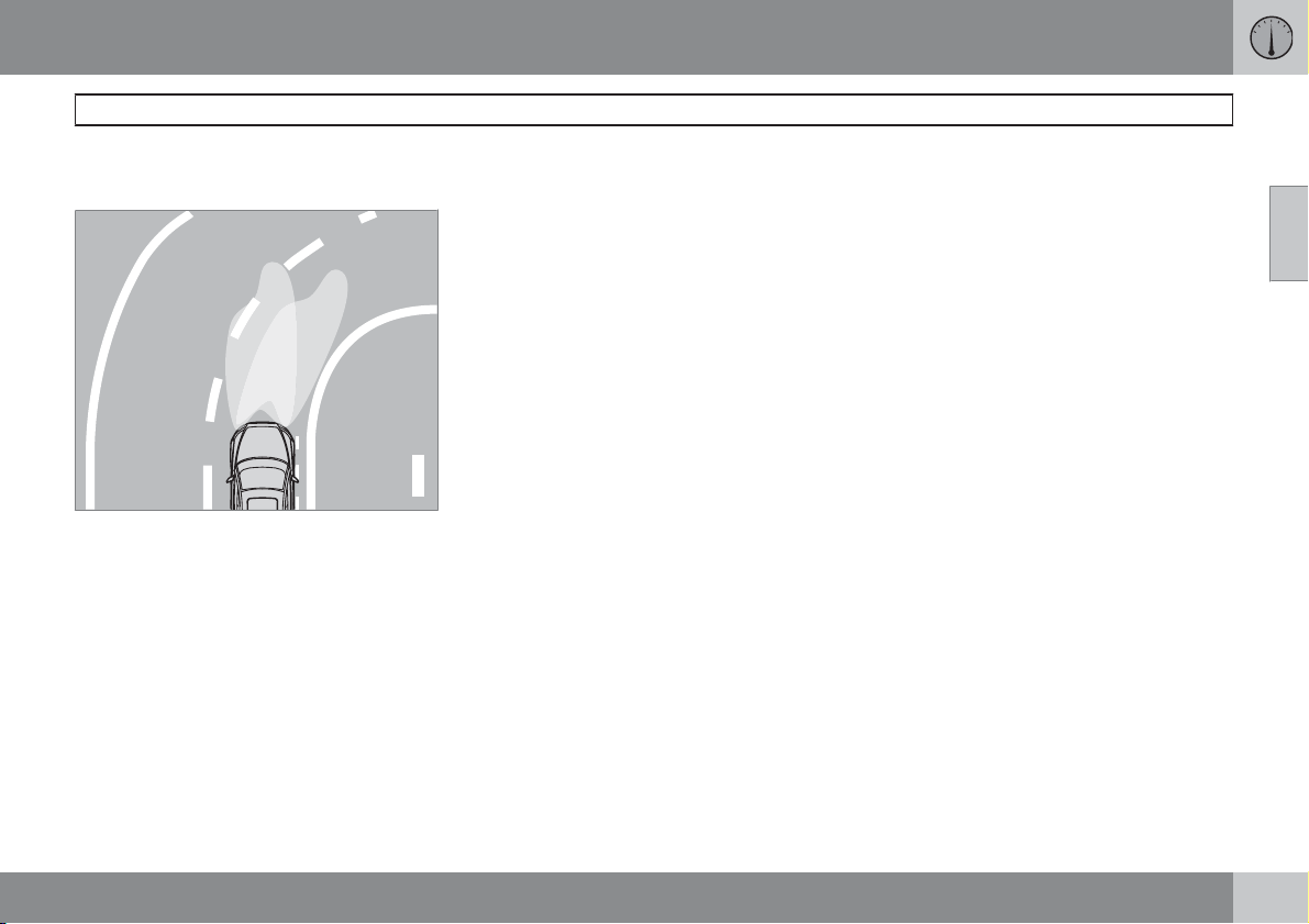
02 Instruments and controls
Lighting panel
The function can be deactivated/activated with
the headlamp control.
Headlamp pattern with function deactivated (left)
and activated (right) respectively.
Brake light
The brake light automatically comes on during
braking.
Emergency brake light and automatic
hazard warning flashers, EBL*
Emergency Brake Lights (EBL) are activated in
the event of heavy braking or if the ABS brakes
are activated. This function means that the
brake light flashes to immediately alert cars
travelling behind.
The system is activated if ABS is used for more
than 0.5 seconds or in the event of heavy braking, however, only when braking from speeds
above 50 km/h. When the speed of the car is
lower than 30 km/h the brake lights shine normally again and the hazard warning flashers
are switched on automatically. The hazard
warning flashers remain on until the car accelerates again but can be deactivated with the
button for hazard warning flashers, see
page 64.
G020789
02
* Option/accessory, for more information, see Introduction.
55
Page 57
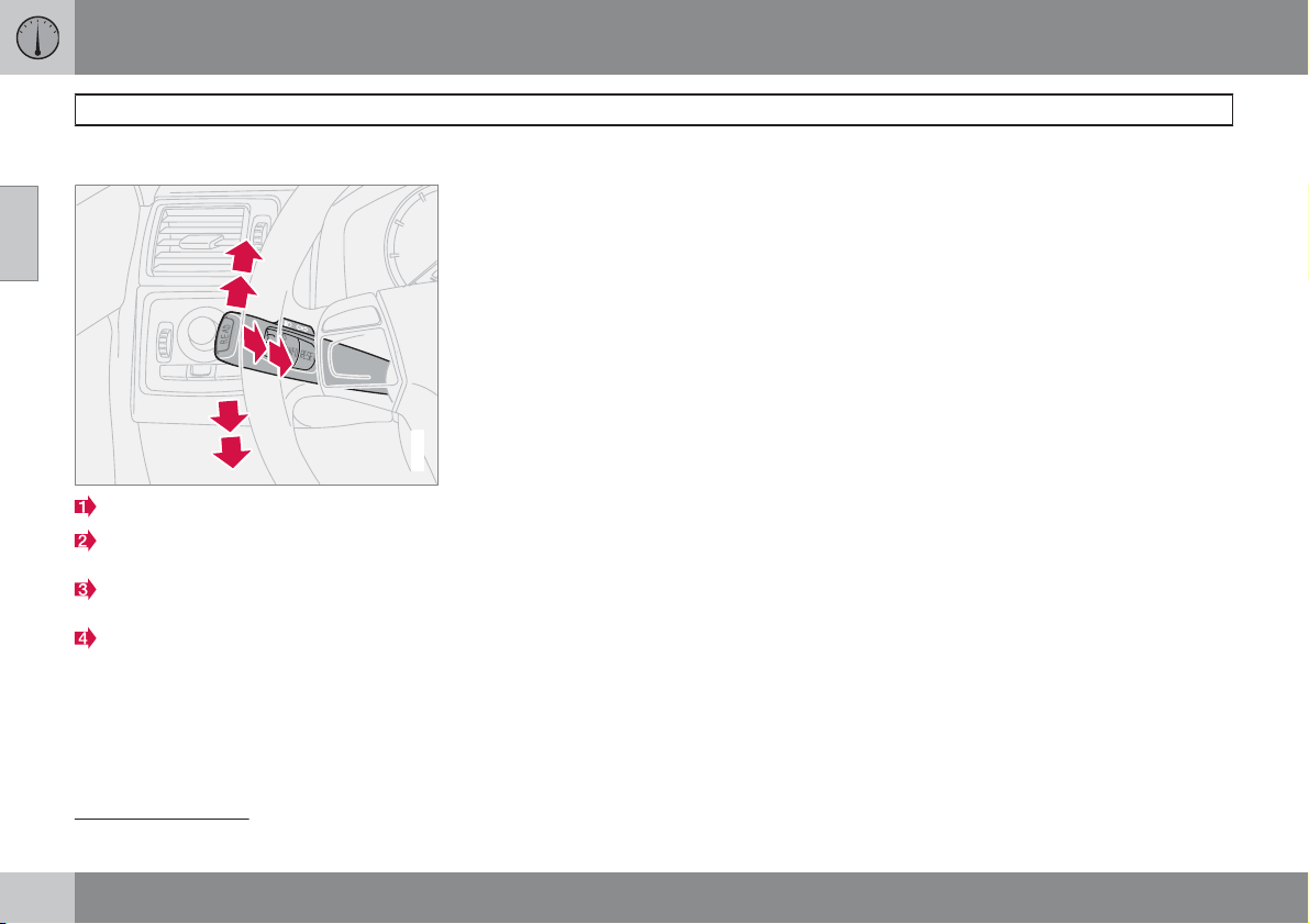
02 Instruments and controls
Left-hand stalk switch
Stalk switch positions
02
Short flash sequence, direction indicators
Continuous flash sequence, direction indicators
Main beam flash and switching from main
to dipped beam
Home safe lighting and switching from
dipped to main beam
Direction indicators
Continuous flash sequence
±
Move the stalk switch up or down to end
2
1
position (2).
The stalk switch remains in its end position and
is moved back manually, or automatically by
steering wheel movement.
3
4
Short flash sequence
±
Move the stalk switch up or down to position (1) and release.
1
2
The direction indicators flash three times and
the stalk switch returns to its home position.
G026380
Main beam flash
±
Move the stalk switch gently towards the
steering wheel to position (3).
Main beam comes on until the stalk switch is
released. Main beam flash only works when the
ignition key is inserted in the ignition switch.
Switching, main and dipped beam
The ignition key must be in position II and the
headlamp control in end position, see
page 53, for main beam to be switched on.
Activating main beam:
±
Move the stalk switch towards the steering
wheel to the end position (4) and release.
Deactivating main beam:
±
Move the stalk switch towards the steering
wheel to position (3) and release.
Home safe lighting
Some of the exterior lighting can be kept
switched on to work as home safe lighting after
the car has been locked. The standard delay is
1
30
seconds, but can be changed to 60 or 90
seconds, see page 74.
1. Remove the key from the ignition switch.
2. Move the stalk switch towards the steering
wheel to the end position (4) and release.
3. Get out of the car and lock the door.
56
1
Factory settings.
Page 58
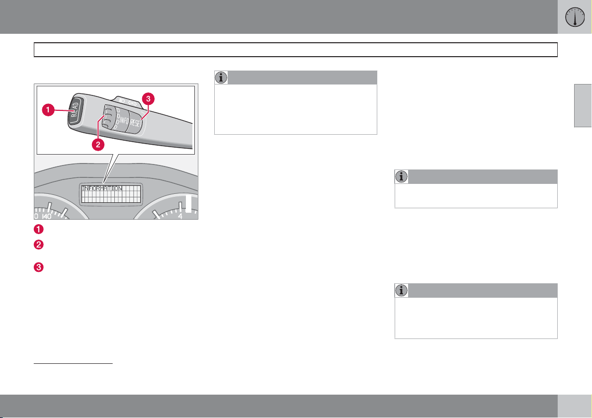
02 Instruments and controls
Left-hand stalk switch
Trip computer*
READ - confirms
Thumbwheel2 - browse between menus
and options in the trip computer list
RESET2 - resets
Controls
To scroll through trip computer information
turn the thumbwheel either up or down in
steps. Continue turning to return to the starting
point.
NOTE
If a warning message interrupts while you
are using the trip computer, this message
must be acknowledged. Acknowledge by
pressing the READ button and revert to the
trip computer function.
Functions
The trip computer displays the following information:
AVERAGE SPEED
•
ACTUAL SPEED MPH*
•
INSTANTANEOUS
•
G029052
AVERAGE
•
KILOMETRES TO EMPTY TANK
•
STC/DSTC, see page 147
•
AVERAGE SPEED
When the ignition is switched off, the average
speed is stored and used as the basis of the
new value when you continue driving. Reset
using the RESET button.
ACTUAL SPEED MPH
Current speed is displayed in mph.
INSTANTANEOUS
Current fuel consumption is calculated every
second. The information on the display is
updated every couple of seconds. When the
car is stationary, "
During the period for regeneration 3 fuel consumption may increase, see page 272.
--.-" appears on the display.
AVERAGE
The average fuel consumption is stored when
the ignition is switched off and remains until the
function is reset. Reset using the RESET button.
NOTE
There may be a slight error in the reading if
a fuel-driven heater is used.
KILOMETRES TO EMPTY TANK
The range to empty is calculated based on the
average fuel consumption over the last 30 km.
No guaranteed range remains when the display
shows " --- km to empty tank". Refuel as
soon as possible.
NOTE
There may be a slight error in the reading if
fuel consumption is changed due to a
change in driving style or if a fuel-driven
heater is used for example.
02
2
No function in cars without trip computer, fuel-driven parking heater as well as stability and traction control system.
3
Only applies to diesel cars with particle filter.
* Option/accessory, for more information, see Introduction.
``
57
Page 59
02
02 Instruments and controls
Left-hand stalk switch
Resetting
1.
2.
AVERAGE SPEED or AVERAGE
Select
Reset with one press on the RESET button. Press and hold the RESET button for
at least five seconds to reset the average
speed and average consumption at the
same time.
58
Page 60
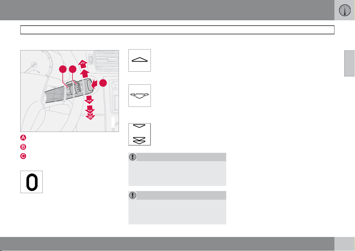
02 Instruments and controls
Right-hand stalk switch
Windscreen wipers
CB
0
Windscreen and headlamp washers
Rain sensor - On/Off
Thumbwheel
Windscreen wipers off
The windscreen wipers are off
when the stalk switch is in position
0.
Single sweep
Raise the stalk switch to make a
single sweep.
0
A
Intermittent wiping
You can adjust and set a suitable
speed for intermittent wiping. Turn
the thumbwheel (C) up for a shorter
interval between sweeps. Turn it
down to increase the delay.
Continuous wiping
G025419
The wipers sweep at normal
speed.
The wipers sweep at high speed.
IMPORTANT
Before activating the wipers during winter
ensure that the wiper blades are not frozen
in, and that any snow or ice on the windscreen is scraped away.
IMPORTANT
Use plenty of washer fluid when the wipers
are cleaning the windscreen. The windscreen must be wet when the windscreen
wipers are operating.
Windscreen/headlamp washer
Move the stalk switch toward the steering
wheel to start the windscreen and headlamp
washers. The wipers will make several more
sweeps once the stalk switch is released.
High-pressure headlamp washing*
High-pressure headlamp washing consumes a
large quantity of washer fluid. To save fluid, the
headlamps are washed as follows:
Dipped beam selected with the switch on lighting panel:
The headlamps are washed the first time the
windscreen is washed. Within the next ten
minutes, they are washed every fifth wash
cycle of the windscreen. In the event of a longer
interval the headlamps are washed each time.
Parking/position lamps selected with the
switch on the lighting panel:
•
Bi-Xenon headlamps are only washed
every fifth wash cycle irrespective of the
time that elapses.
Halogen headlamps are not washed.
•
The switch on the lighting panel is in position
0:
•
Bi-Xenon headlamps are only washed
every fifth wash cycle irrespective of the
time that elapses.
Halogen headlamps are not washed.
•
02
``
* Option/accessory, for more information, see Introduction.
59
Page 61
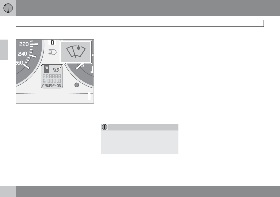
02 Instruments and controls
Right-hand stalk switch
Rain sensor*
02
The rain sensor automatically activates the
windscreen wipers based on how much water
it detects on the windscreen. The sensitivity of
the rain sensor can be adjusted using the
thumbwheel (C), see page 59.
Turn the thumbwheel upwards for higher sensitivity and downwards for lower sensitivity, (an
extra sweep is made when the thumbwheel is
turned upwards).
On/Off
When activating the rain sensor, the ignition
key must be in position I or II and the windscreen wiper stalk switch must be in position
0 (not activated).
Activating the rain sensor:
±
Press the button (B), see page 59. A display
symbol shows that the rain sensor is
active.
To turn the rain sensor off, either:
1. Press button (B)
2. Press the stalk switch downward to
another wiper program. If the stalk switch
is raised, the rain sensor will remain active,
the wipers make an extra sweep and then
return to rain sensor mode when the stalk
is released to position 0 (not activated), see
G029053
page 59.
The rain sensor is automatically deactivated
when the key is removed from the ignition
switch or five minutes after the ignition is
switched off.
IMPORTANT
At an automatic car wash: Deactivate the
rain sensor by pressing the button (B) while
the ignition key is in position I or II. Otherwise, the windscreen wipers could start
swiping and become damaged.
Thumbwheel
Use the thumbwheel to adjust the frequency of
wiper sweeps when intermittent wiping is
selected, or the sensitivity to rain when the rain
sensor is selected.
60
* Option/accessory, for more information, see Introduction.
Page 62
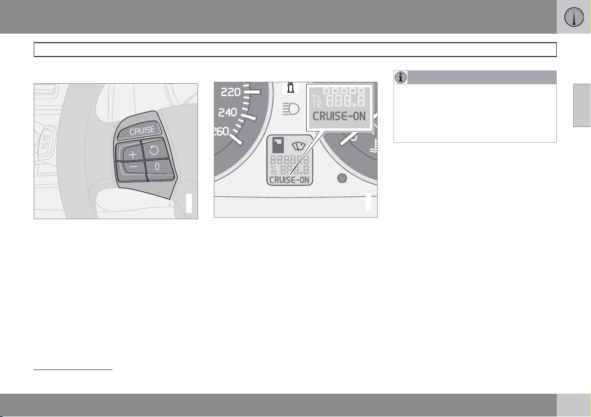
02 Instruments and controls
Cruise control*
Activating
The controls for cruise control are to the left of
the steering wheel.
Setting the desired speed:
1.
Press the CRUISE button. CRUISE is
shown on the combined instrument panel.
2.
Touch + or – to lock the vehicle speed.
CRUISE-ON appears in the combined
instrument panel.
Cruise control cannot be engaged at speeds
below 30 km/h or above 200 km/h.
Increasing or decreasing speed
G020141
±
Increase or decrease the speed by pressing and holding + or –. The speed of the car
when the button is released is set as the
new speed.
A brief press (less than half a second) on + or
– changes the speed by 1 km/h or 1 mph
NOTE
A temporary increase in speed (less than
one minute) using the accelerator, such as
while overtaking, does not affect the cruise
control setting. When you release the accelerator, the car will return to the programmed
speed.
02
Temporary disengagement
±
Press 0 to disengage the cruise control
temporarily. CRUISE will be shown on the
combined instrument panel. The speed set
G029054
1
.
earlier is stored in the memory.
The cruise control is also temporarily disengaged when:
the brake pedal or clutch pedal is
•
depressed
speed falls below 25–30 km/h1 when trav-
•
elling uphill
the gear selector is moved to position N
•
wheel spin or wheel lock-up occurs
•
a temporary increase in speed lasts longer
•
than one minute.
1
Depending on engine type.
* Option/accessory, for more information, see Introduction.
``
61
Page 63
02 Instruments and controls
Cruise control*
Return to the set speed
02
Disengaging
±
Press CRUISE to disengage the cruise
control.
bined instrument panel.
– Press this button to resume the
previously set speed.
appears on the combined
ON
instrument panel.
CRUISE ON clears on the com-
CRUISE
62
* Option/accessory, for more information, see Introduction.
Page 64
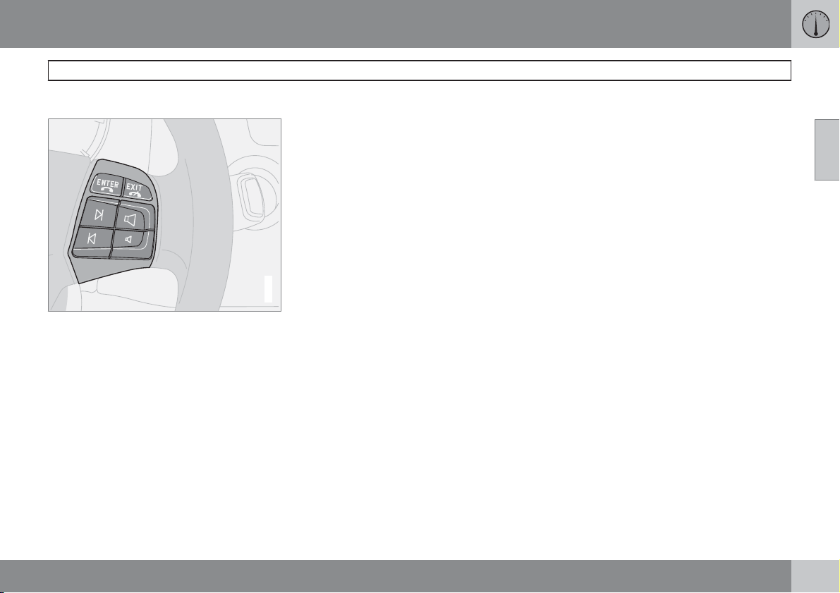
Button functions
The four buttons at the bottom of the steering
wheel keypad control the radio and the phone.
The function of a button depends on which
system is active. The steering wheel keypad
can be used to scroll between preset stations,
change CD tracks and adjust the volume.
±
Press and hold one of the arrow keys to
fast forward/reverse or search for the next
station.
The phone must be switched on to adjust audio
system settings. It must be activated with the
ENTERkey to enable control of the phone system with the arrow keys.
To return to Audio only, press EXIT.
02 Instruments and controls
Keypad in the steering wheel*
02
G020142
* Option/accessory, for more information, see Introduction.
63
Page 65
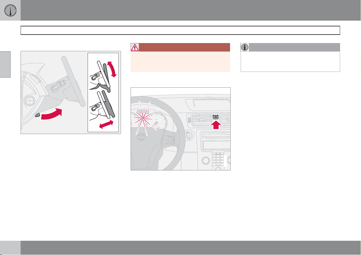
02 Instruments and controls
Steering wheel adjustment, hazard warning flashers
Steering wheel adjustment
02
The steering wheel can be adjusted for both
height and reach.
1. Pull the lever towards you to release the
steering wheel.
2. Adjust the steering wheel to the position
that suits you best.
3. Push back the lever to fix the steering
wheel in place. If the lever is stiff, press the
steering wheel lightly at the same time as
you push the lever back.
WARNING
Adjust the steering wheel before driving off,
never while driving. Before driving, check
that the steering wheel is fixed in position.
Hazard warning flashers
G020143
Use the hazard warning flashers (all direction
indicators flash) when the car is stopped where
it could be a traffic hazard or obstruction. Press
the button to activate the function.
A sufficiently violent collision or heavy braking
activates the hazard warning flashers automatically, see page 55. The function can be deactivated with the button.
NOTE
Regulations regarding the use of hazard
warning flashers vary from country to country.
G020144
64
Page 66
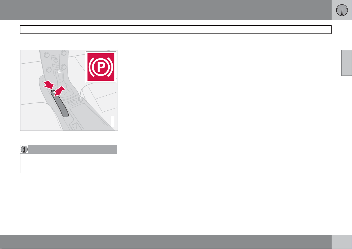
02 Instruments and controls
Parking brake
Parking brake (handbrake)
The lever is located between the front seats.
NOTE
The warning lamp symbol in the combined
instrument panel illuminates irrespective of
how hard the parking brake is applied.
How to Apply the parking brake
1. Press the foot brake pedal down firmly.
2. Pull up the parking brake lever up firmly to
its full extent.
3. Release the foot brake pedal and make
sure that the car is at a standstill position.
4. If the vehicle rolls, the parking brake lever
must be pulled more firmly.
When parking a vehicle always put the gear
selector in position 1 (for manual transmission)
or P (for automatic transmission).
Parking on a hill
If the car is parked facing uphill; turn the wheels
away from the kerb.
If the car is parked facing downhill; turn the
wheels toward the kerb.
How to release the parking brake
1. Press the foot brake pedal down firmly.
G018260
2. Pull the parking brake lever up slightly,
press the button, release the parking brake
lever and release the button.
02
65
Page 67
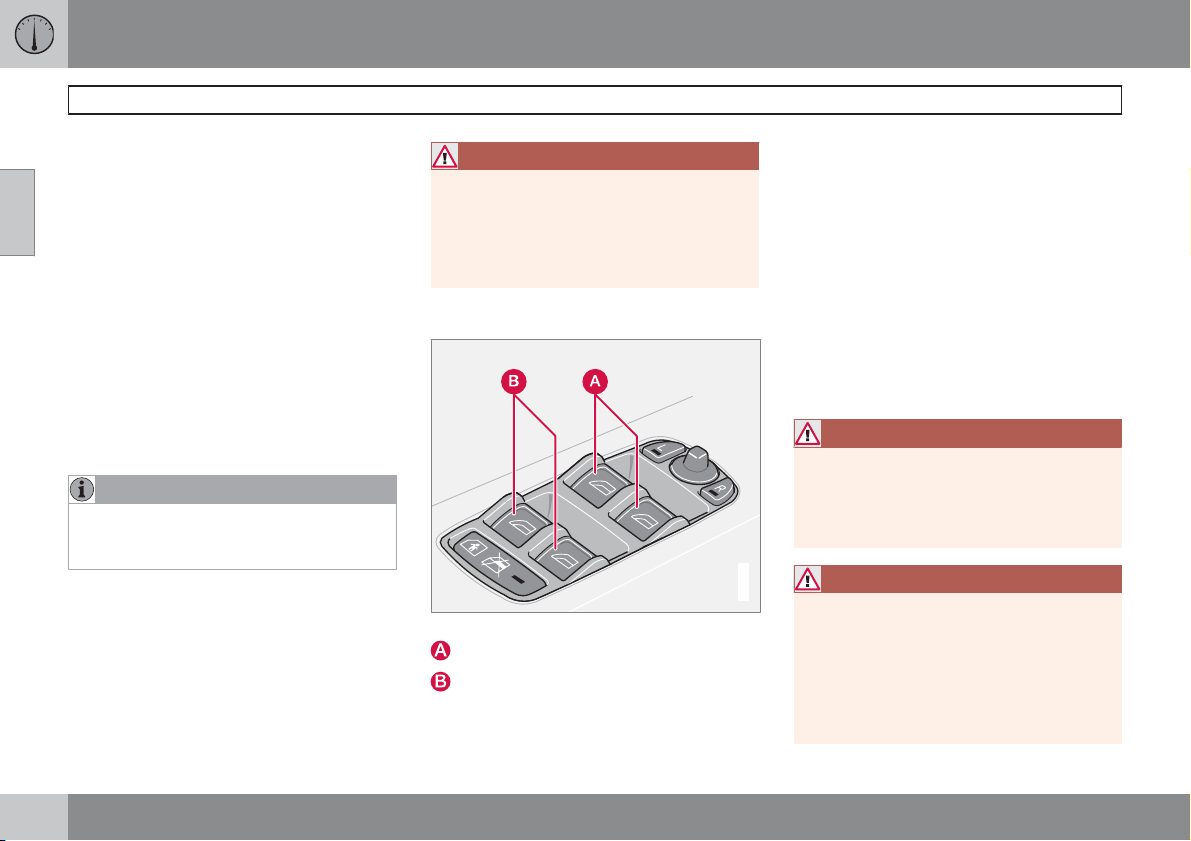
02 Instruments and controls
Power windows
Operation
The power windows are operated using the
02
controls in the doors. The ignition key must be
in position I or II for the power windows to
operate.
The windows continue to work for a limited
amount of time when the car is stopped and
ignition key is removed, provided none of the
doors is opened. Operate the windows with
caution.
To open a window:
±
Depress the front of the control.
To close a window:
±
Raise the front of the control.
NOTE
One way to reduce the pulsating wind noise
when the rear windows are open is to also
open the front windows slightly.
Remote control and lock buttons
To operate the power windows with lock buttons and remote control, see pages 112 and
121.
WARNING
Make sure that children and other passengers cannot be trapped in any way when
closing the windows. Pay close attention if
the rear door windows are controlled from
the driver's door or if the windows are
closed with the remote control.
Driver's door
Controls, power windows.
Front window controls
Rear window controls
The driver can operate all of the power windows from the driver's seat.
The windows can be opened and closed in two
ways:
Manual operation
Depress one of the controls (A) or (B) gently or
raise it gently. The power window opens or
closes as long as the switch is actuated.
Automatic operation
Fully depress one of the controls (A) or raise it,
then release. The side window will then open
or close automatically. If the window is
obstructed by an object, the movement will
stop.
WARNING
The function that interrupts the movement
of the windows in the event of them being
blocked works with both automatic and
manual closing, although not with pinch
protection deployed.
G017439
WARNING
If there are children in the car:
Remember to switch off the supply to the
power windows by removing the ignition
key if the driver leaves the car.
Make sure that children and other passengers cannot be trapped in any way when
closing the windows.
66
Page 68
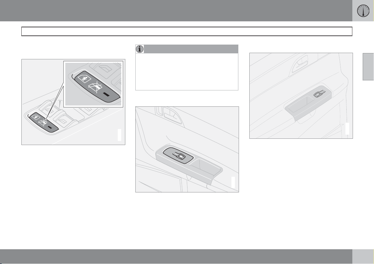
02 Instruments and controls
G028208
Power windows
Blocking power windows in the rear
doors
Blocking rear power windows and electric child
safety locks*.
The light in the switch is lit
The rear door windows can only be operated
from the driver's door.
The light in the switch is extinguished
The rear door windows can be operated both
with the control on each rear door and with the
controls on the driver's door.
NOTE
If the car has electric child safety locks on
the rear doors, the light indicates that these
are also activated. The doors then cannot
be opened from the inside. A text message
is shown on the display when the electric
child safety locks are activated.
Front passenger seat
G017440
Front passenger seat.
The control in the front passenger door operates that window only.
Rear power windows
The rear door windows can be operated with
the control on each door or with the switch on
the driver's door. If the light in the switch for
blocking the rear power windows (located in
the control panel in the driver's door) is lit, the
rear door windows can only be operated from
the driver's door. The windows in the rear
G019511
doors are operated in the same way as the
windows in the front doors.
02
67
Page 69
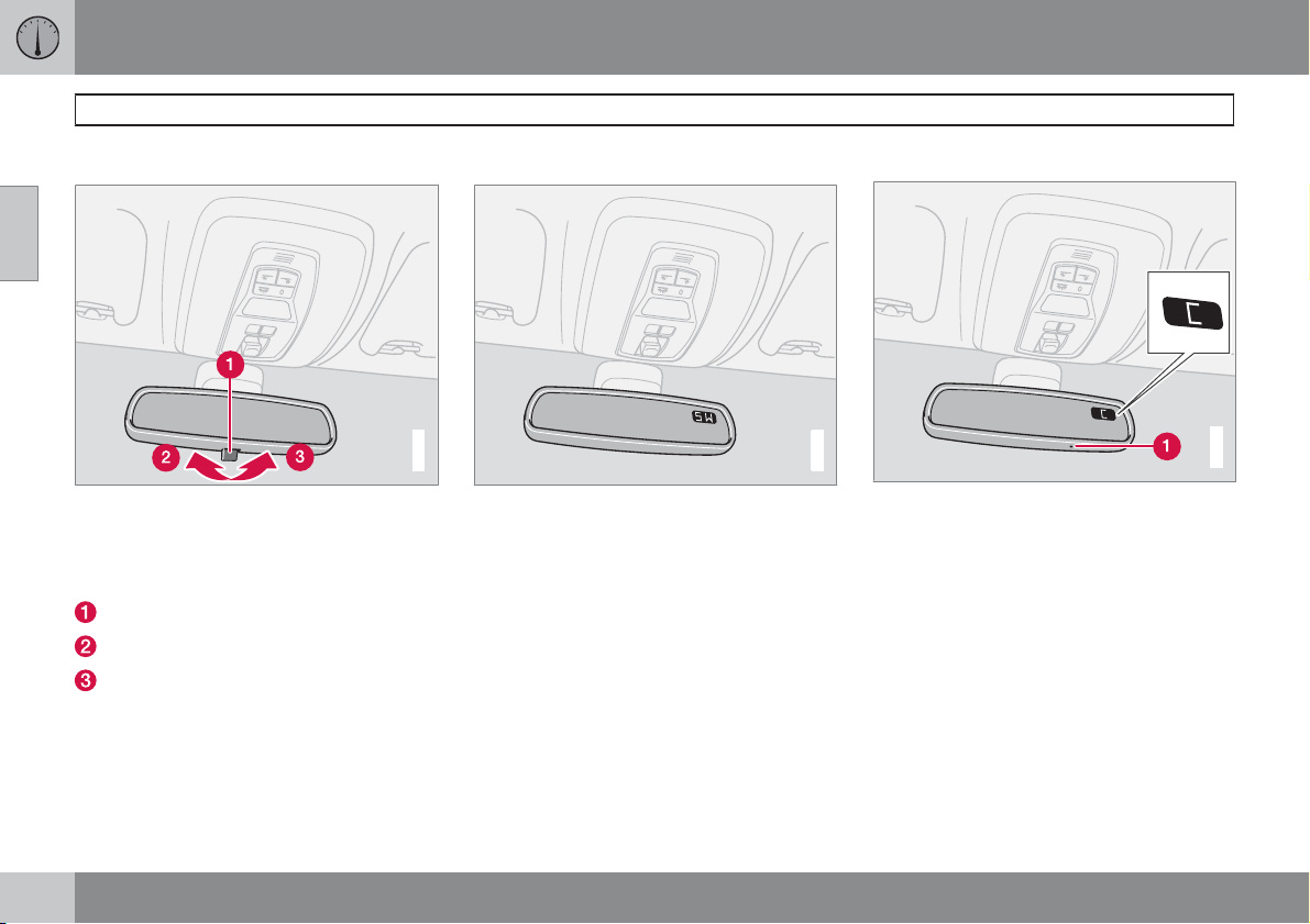
02 Instruments and controls
G031045
Rearview and door mirrors
Interior rearview mirror
02
Bright light from behind could be reflected in
the rearview mirror and dazzle the driver. Use
dimming when disturbed by light from behind.
Dipping
Control for dimming
Normal position
Dimmed position.
Automatic dimming*
Bright light from behind is automatically
dimmed by the rearview mirror. The control (1)
is not available in mirrors with automatic dimming.
Interior rearview mirror with compass*
G020146
The upper right-hand corner of the rearview
mirror has an integrated display that shows the
compass direction in which the front of the car
is pointing. Eight different directions are shown
with English abbreviations: N (north), NE (north
east), E (east), SE (south east), S (south), SW
(south west), W (west) and NW (north west).
Calibrating the compass
G031043
The earth is divided into 15 magnetic zones.
The compass is set for the geographical area
to which the car was delivered. The compass
should be calibrated if the car is moved across
several magnetic zones.
1. Stop the car in a wide open area with the
engine running at idling speed.
2. Press and hold button (1) for at least 6 seconds. Following which, the character C is
shown (the button is concealed so use a
paper clip for example to press it in).
3. Press and hold button (1) for at least 3 seconds. The number for the current magnetic
zone is displayed.
68
* Option/accessory, for more information, see Introduction.
Page 70
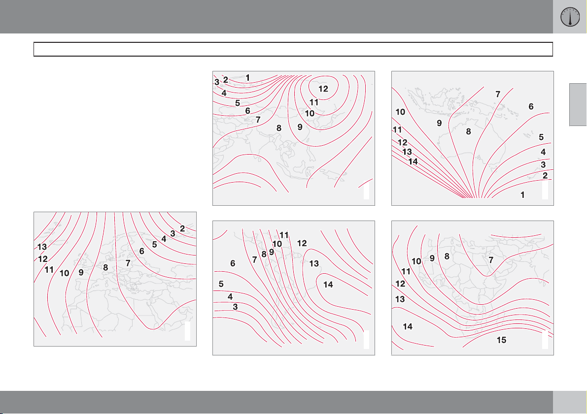
02 Instruments and controls
G020153
G020154
Rearview and door mirrors
4. Press the button (1) repeatedly until the
number for the required magnetic zone (
) is shown, refer to the map of magnetic
15
1–
zones for the compass.
5. Wait until the display returns to showing
the character
C.
6. Following which, press and hold the button
in for 9 seconds and select
drive cars and
R for right-hand drive.
L for left-hand
7. Drive slowly in a circle with a maximum
speed of 10 km/h until a compass direction
is shown on the display, which indicates
that the calibration is complete.
Magnetic zones, Europe.
Magnetic zones, Asia.
G020150
Magnetic zones, South America.
02
G020151
Magnetic zones, Australia.
G020152
Magnetic zones, Africa.
``
69
Page 71
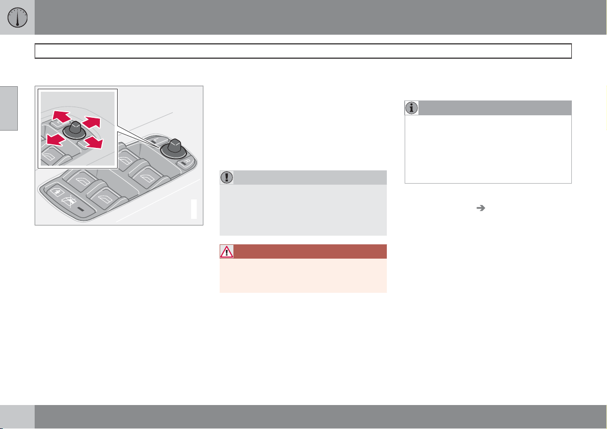
02 Instruments and controls
Rearview and door mirrors
Door mirrors
02
The controls for adjusting the two door mirrors
are at the front of the driver's door armrest. The
rearview mirrors can be operated in ignition
position I and II.
1.
Press the L button for the left-hand door
mirror or the R button for the right-hand
door mirror. The light on the button illuminates.
2. Adjust the position with the joystick in the
centre.
3.
Press the L or R button again. The light
goes out.
Retractable power door mirrors*
The mirrors can be retracted for parking/driving
in narrow spaces. This can be carried out in
ignition position I and II.
Retracting the mirrors
1.
Press the L and R button at the same time.
2. Release the buttons. The mirrors automatically stop in the fully retracted position.
IMPORTANT
Do not use a scraper to remove ice from the
mirrors as this could scratch the glass and
the water and dirt-repellent coating* could
G018252
be damaged. Use the defroster function
instead, see page 85 or 89.
WARNING
Both door mirrors are the wide angled type
to provide optimal vision. Objects may
appear further away than they actually are.
Folding out the mirrors
1.
Press the L and R button at the same time.
2. Release the buttons. The mirrors automatically stop in the fully extended position.
Automatic retracting/extending
When the car is locked/unlocked with the
remote control or using the Keyless-system,
see page 117, the door mirrors are automatically retracted/extended.
NOTE
The door mirrors will not be extended automatically during unlocking if they were
retracted using the controls in the door.
If the car is locked with the remote control
and is then started, the door mirrors will still
be extended.
The function can be activated/deactivated
under Car settings Retract mirrors when
locking, see page 74 for a description of the
menu system.
Resetting to neutral
Mirrors that have been moved out of position
by an external force must be reset to the neutral
position for electric retracting and extending to
work.
1.
Use the L and R buttons to retract the mirrors.
2.
Extend the mirrors again with the L and R
button. The mirrors are now reset to the
neutral.
70
* Option/accessory, for more information, see Introduction.
Page 72
02 Instruments and controls
Rearview and door mirrors
Home safe and approach lighting
The light* on the door mirrors illuminates when
the approach lighting or home safe lighting is
activated.
Blind Spot Information System, BLIS*
BLIS is an information system that under certain conditions can help to draw the driver's
attention to vehicles moving in the same direction in the so-called "blind spot", see
page 151.
Water and dirt-repellent coating*
The front side windows and/or door
mirrors are treated with a coating
which improves the view in poor weather conditions. For information on maintenance, see
page 189.
Rearview and door mirrors
In certain weather conditions, the function of
the dirt-repellent coating is improved if the
door mirror defrosters are used, see
page 85 or 88.
Heat the door mirrors:
If they are covered with ice or snow.
•
In heavy rain and dirty road conditions.
•
If they are misted.
•
IMPORTANT
Do not use a metal ice scraper to remove ice
from the windows. The water and dirt-repellent coating could be damaged. Use the
defroster to remove ice from the mirrors. An
ice scraper could scratch the mirror glass!
02
* Option/accessory, for more information, see Introduction.
71
Page 73
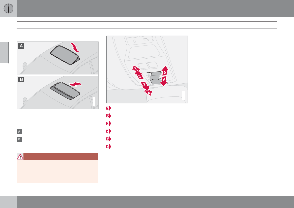
02 Instruments and controls
Power sunroof*
Open positions
02
The sunroof controls are located in the roof
panel. The sunroof can be opened in two positions:
Ventilation position, up at the rear edge
Sliding position, backwards/forwards
The ignition key must be in position I or II.
WARNING
If there are children in the car:
Switch off the supply to the power sunroof
by removing the ignition key if the driver
leaves the car.
G007503
Opening, automatic
Opening, manual
Closing, manual
Closing, automatic
Opening, ventilation position
Closing, ventilation position
Ventilation position
Open:
±
Press the rear edge of the control (5)
upward.
Close:
±
Pull the rear edge of the control (6) downward.
From ventilation position to fully open sunroof:
±
Pull the control rearward to the end position (1) and release.
Sliding position
Automatic operation
±
Pull the control past the point of resistance
(2) to the rear end position (1) or past the
G029222
point of resistance (3) to the forward end
position (4) and release. The sunroof
opens/closes completely.
Manual operation
Open:
±
Pull the control rearward to the point of
resistance (2). The sunroof moves toward
the fully open position as long as the button
is held in this position.
Close:
±
Press the control forward to the point of
resistance (3). The sunroof moves toward
the closed position as long as the button is
held in this position.
72
* Option/accessory, for more information, see Introduction.
Page 74
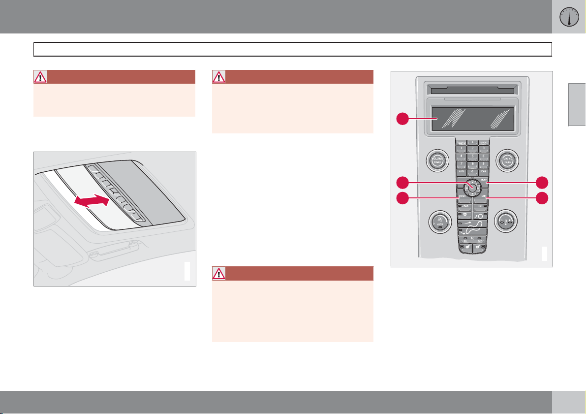
02 Instruments and controls
A
D
B
C
E
G026307
Power sunroof*
WARNING
The sunroof's pinch-protection function
only operates during automatic closing, not
manual closing.
Closing with remote control or lock
button
±
One long press on the lock button closes
the sunroof and all the windows. The doors
and the boot lid are locked.
If you need to interrupt closing:
±
Press the lock button again.
WARNING
Make sure that children or other passengers
are not in danger of becoming trapped in
any way when closing the sunroof with the
remote control. Always operate the sunroof
with caution.
02
Sunscreen
The sunroof features a manual, sliding interior
sunscreen. The sunscreen slides back automatically when the sunroof is opened. Grip the
handle and slide the screen forward to close it.
Pinch protection
The sunroof's pinch protection function is activated if the hatch is blocked by an object. If
blocked, the sunroof will stop and automatically open to the previous position.
G020157
WARNING
The sunroof's pinch protection function only
operates during automatic closing, not during manual closing.
Make sure that nobody is in danger of
becoming trapped in any way when closing
the sunroof.
Control panel.
* Option/accessory, for more information, see Introduction.
73
Page 75
02 Instruments and controls
Personal preferences
Possible settings
Personal preferences can be set for some of
02
the car's functions. This applies to locks, climate control and audio functions. For audio
functions, see page 226.
Control panel
Display
MENU
EXIT
ENTER
Navigation
Use
The settings are shown on the display (A).
Open the menu to enter settings:
1.
Press MENU (B).
2.
Scroll, for example, to Car settings with
the navigation button (E).
3.
Press ENTER (D).
4. Select an alternative with the navigation
button (E).
5.
Press ENTER to activate the selection.
Close the menu:
±
Press EXIT (C) for approximately one second.
Clock, adjustment
The hour and minute are each adjusted separately.
1. Use the numbers on the keypad or "arrow
up" or "arrow down" on the navigation button (E).
2. Select the number for adjustment using
"arrow right" or "arrow left" on the navigation button.
3.
Press ENTER to start the clock.
NOTE
If the car has a 12-hour clock then AM/PM
is selected using "arrow up" or "arrow
down" after the final minute number has
been adjusted.
Climate settings
Automatic blower adjust
The fan speed can be set to AUTO mode in
cars equipped with ECC:
±
Select from Low, Normal and High.
Recirculation timer
When the timer is active, the air recirculates for
3-12 minutes, depending on the outside air
temperature.
±
Select
On/Off depending on whether or
not you wish the recirculation timer to be
active.
Reset all
Resets the climate function options to the factory settings.
Car settings
Retract mirrors when locking*
When the car is locked/unlocked with the
remote control the door mirrors can be retracted/extended automatically. The On/Off
options are available.
Reduced guard*
The deadlocks function can be temporarily
deactivated and the alarm level reduced if
someone wishes to remain in the car and the
doors have to be locked from the outside. The
Activate once and Ask on exit options are
available, see pages 122 and 126.
Unlock confirm. light
The hazard warning flashers can provide feedback when the car is unlocked with the remote
control. The On/Off options are available.
Lock confirm. light
The hazard warning flashers can provide feedback when the car is locked with the remote
control. The
On/Off options are available.
74
* Option/accessory, for more information, see Introduction.
Page 76
02 Instruments and controls
Personal preferences
Doors – auto lock
When the speed of the car exceeds 7 km/h the
doors and boot lid can be locked automatically.
On/Off options are available. Pulling the
The
door handle twice unlocks and opens the
doors from the inside.
Doors unlock
There are two alternatives for unlocking:
All doors – one press of the remote control
•
unlocks all doors and the boot lid.
Driver's door first, then all others – one
•
press of the remote control unlocks the
driver's door. A second press then unlocks
the passenger door and the boot lid.
Keyless entry*
All doors - all doors are unlocked simul-
•
taneously.
Doors on same side – front and rear
•
doors on the same side are unlocked
simultaneously.
Both front doors – both front doors are
•
unlocked simultaneously.
Either front door – any door or the boot
•
lid can be unlocked separately.
Simultaneous closing/opening of all
windows
This function can be selected for the lock button on the remote control and the front doors'
central locking button, as well as the outside
door handle button on cars with the keyless
system:
Auto. close all windows - all windows
•
and the sunroof are closed simultaneously
with one long press on the lock button.
This function can be selected for the unlock
button on the remote control and the front
doors' central locking button:
Auto. open all windows – all windows are
•
opened simultaneously with one long
press on the unlock button.
Approach lighting
Select the time the car's lights should remain
on when the approach lighting button is
pressed. The following alternatives are available: 30/60/90 seconds.
Home safe lighting
Select the time the car's lights should remain
on when the left-hand stalk switch is pulled
back after the ignition key has been removed.
The following alternatives are available:
30/60/90 seconds.
Information
VIN number - (Vehicle Identification Num-
•
ber) is the car's unique identity number.
Number of keys - The number of keys
•
registered for the car is shown.
02
* Option/accessory, for more information, see Introduction.
75
Page 77
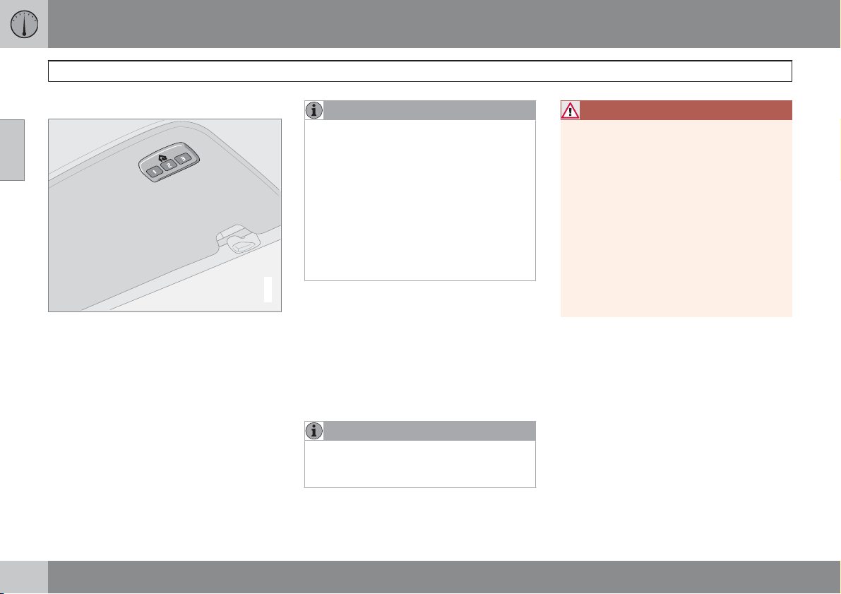
02 Instruments and controls
HomeLink EU*
General
02
HomeLink is a programmable remote control
which can control up to three different devices
(e.g. garage door, alarm system, outdoor lighting and indoor lighting etc.) and in doing so
replace their remote controls. HomeLink is
supplied built into the left-hand sun visor.
HomeLink's panel consists of three programmable buttons and one indicator lamp.
NOTE
HomeLink is designed to be inoperable if
the car is locked from the outside.
Save the original remote controls for future
programming (e.g. for purchasing a new
car).
Erase the programming for the buttons
when selling the car.
Metallic sun visors should not be used in
cars equipped with HomeLink. This could
have a negative effect on the HomeLink
function.
G030070
Operation
When HomeLink is fully programmed it can be
used in place of the separate original remote
controls.
Press the programmed button to activate the
garage door, alarm system etc. The indicator
lamp illuminates for the time that the button is
kept depressed.
NOTE
In the event that the ignition is not activated,
HomeLink operates for 30 minutes after the
driver's door has been opened.
The original remote controls can of course be
used in parallel with HomeLink.
WARNING
If HomeLink is used to operate a garage
door or gate, ensure that nobody is in the
vicinity of the door or gate while it is in
motion.
Do not use the HomeLink remote control for
any garage door that does not have safety
stop and safety reverse. The garage door
must react immediately when it detects that
something is preventing its movement, and
stop directly and reverse. A garage door
without these characteristics could cause
personal injury. For further information, ring
the HomeLink Hotline: 008000 466 354 65
(free of charge). They can also be contacted
via the Internet: www.homelink.com.
Programming for the first time
The first step erases the memory in HomeLink
and must not be carried out when only one
individual button is being reprogrammed.
1. Depress the two outer buttons and do not
release until the indicator lamp starts to
flash after approx. 20 seconds. The flashing indicates that HomeLink is set in "learn
mode" and is ready to be programmed.
2. Position the original remote control 2-8 cm
from HomeLink. Monitor the indicator
lamp.
76
* Option/accessory, for more information, see Introduction.
Page 78
02 Instruments and controls
HomeLink EU*
The particular distance that is required
between the original remote control and
HomeLink depends on the programming of
the device in question. Perhaps several
attempts will be required at different distances. Maintain each position for approx.
15 seconds before trying a new one.
3. Depress the button for the original remote
control and the button to be programmed
on HomeLink simultaneously. Do not
release the buttons until the indicator lamp
has changed over from slow to rapid flashing. The rapid flashing indicates successful
programming.
4. Test the programming by depressing the
programmed button on HomeLink and
watching the indicator lamp:
Constant glow: The indicator lamp illu-
•
minates with a constant glow when the
button is kept depressed, this indicates
that the programming is complete. The
garage door, gate or similar should now
be activated when the programmed
HomeLink button is depressed.
Glow not constant: The indicator lamp
•
flashes quickly for approx. 2 seconds
and then changes over to a constant
glow for approx. 3 seconds. This process is repeated for approx. 20 seconds
and indicates that the device has a "rolling code". The garage door, gate or similar is not activated when the programmed HomeLink button is
depressed. Continue the programming
in accordance with the following.
5.
Locate the "programming button
receiver for the garage door for example,
normally located close to the antenna's
bracket on the receiver. If you have difficulty in finding the button, look in the manufacturer's manual or call the HomeLink
Hotline: 008000 466 354 65 (free of
charge). They can also be contacted via
the Internet: www.homelink.com
6. Depress and release the "programming
button". The button flashes for approx. 30
seconds and the next step must be carried
out within this period.
7. Depress the programmed button on
HomeLink, while the "programming button" is still flashing, keep it depressed for
approx. 3 seconds and then release.
Repeat the press/hold/release sequence
up to 3 times to conclude the programming.
1
" on the
Programming individual buttons
To reprogram an individual button, proceed in
accordance with the following:
1. Depress the required button on HomeLink
and do not release until step 3 has been
completed.
2. When the indicator lamp on HomeLink
starts to flash, after approx. 20 seconds,
position the original remote control 2-8 cm
from HomeLink. Monitor the indicator
lamp.
The particular distance that is required
between the original remote control and
HomeLink depends on the programming of
the device in question. Perhaps several
attempts will be required at different distances. Maintain each position for approx.
15 seconds before trying a new one.
3. Depress the button on the original remote
control. The indicator lamp will start to
flash. When the flashing has changed over
from a slow to a rapid flashing - release
both buttons. The rapid flashing indicates
successful programming.
4. Test the programming by depressing the
programmed button on HomeLink and
watching the indicator lamp:
02
1
Button designation and colour vary depending on manufacturer.
* Option/accessory, for more information, see Introduction.
``
77
Page 79
02 Instruments and controls
HomeLink EU*
Constant glow: The indicator lamp illu-
•
02
minates with a constant glow when the
button is kept depressed, this indicates
that the programming is complete. The
garage door, gate or similar should now
be activated when the programmed
HomeLink button is depressed.
Glow not constant: The indicator lamp
•
flashes quickly for approx. 2 seconds
and then changes over to a constant
glow for approx. 3 seconds. This process is repeated for approx. 20 seconds
and indicates that the device has a "rolling code". The garage door, gate or similar is not activated when the programmed HomeLink button is
depressed. Continue the programming
in accordance with the following.
5.
Locate the "programming button
receiver for the garage door for example,
normally located close to the antenna's
bracket on the receiver. If you have difficulty in finding the button, look in the manufacturer's manual or call the HomeLink
Hotline: 008000 466 354 65 (free of
charge). They can also be contacted via
the Internet: www.homelink.com
6. Depress and release the "programming
button". The button flashes for approx. 30
2
" on the
seconds and the next step must be carried
out within this period.
7. Depress the programmed button on
HomeLink, while the "programming button" is still flashing, keep it depressed for
approx. 3 seconds and then release.
Repeat the press/hold/release sequence
up to 3 times to conclude the programming.
Erasing programming
It is only possible to erase the programming for
all the buttons on HomeLink, not for individual
buttons.
±
Depress the two outer buttons and do not
release until the indicator lamp starts to
flash after approx. 20 seconds.
> HomeLink is now set in so-called "learn
mode" and is ready to be programmed
once more, see page 76.
2
Button designation and colour vary depending on manufacturer.
78
* Option/accessory, for more information, see Introduction.
Page 80
02 Instruments and controls
02
79
Page 81
General information on climate control................................................... 82
Manual climate control, AC..................................................................... 84
Electronic climate control, ECC*............................................................. 87
Air distribution......................................................................................... 91
Fuel-driven engine block heater
and passenger compartment heater*..................................................... 92
Fuel-driven auxiliary heater* (diesel)....................................................... 95
80
* Option/accessory, for more information, see Introduction.
G020906
Page 82
CLIMATE CONTROL
03
Page 83
03 Climate control
General information on climate control
Air conditioning
The climate control system cools or heats as
well as dehumidifies the air in the passenger
compartment. The car is equipped with either
manual (AC) or electronic climate control (ECC,
Electronic Climate Control).
03
NOTE
The air conditioning system can be
switched off, but to ensure the best possible
air in the passenger compartment and prevent the windows from misting, it should
always be on.
Misting windows
Remove misting on the insides of the windows
by first using the defroster function.
To reduce the risk of misting, clean the windows with a normal window cleaning agent.
Ice and snow
Remove ice and snow from the climate control
air intake (the grille between the bonnet and the
windscreen).
Fault tracing and repair
Entrust fault tracing and repair of the climate
control system to an authorised Volvo workshop only.
Refrigerant
The air conditioning system contains R134a
refrigerant. This refrigerant contains no chlorine, which means that it is harmless to the
ozone layer. The system must only be charged
with R134a refrigerant. Have an authorised
Volvo workshop carry out this work.
Passenger compartment filter
All air entering the car's passenger compartment is only cleaned with one filter. This must
be replaced at regular intervals. Follow the
Volvo Service Programme for the recommended replacement intervals. If the car is
used in a severely contaminated environment,
it may be necessary to replace the filter more
often.
NOTE
There are different types of passenger compartment filter. Make sure that the correct
filter is fitted.
Display
There is a display above the climate control
panel. This displays climate control settings.
Personal preferences
You can set preferences for two climate control
functions:
Fan speed in AUTO mode (applies only to
•
cars with ECC).
Recirculation timer for passenger com-
•
partment air.
For information about these settings, see
page 74.
82
Page 84
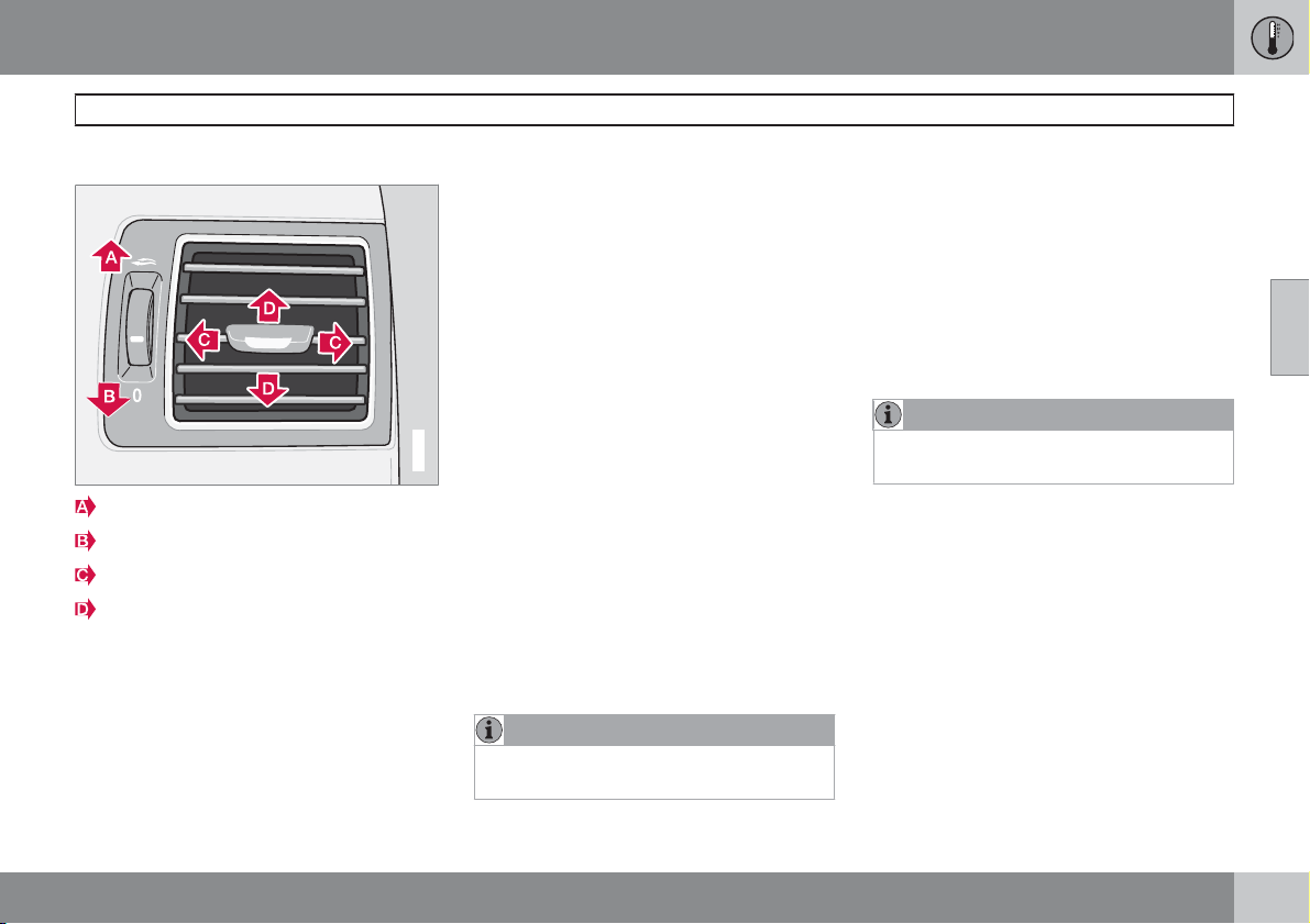
03 Climate control
General information on climate control
Air vents in the dashboard
Open
Closed
Lateral airflow
Vertical airflow
Aim the outer vents towards the side windows
to remove misting from the front side windows.
During cold weather - Close the centre vents
for optimum comfort and best demisting.
ECC*
Actual temperature
The temperature you select corresponds to the
physical experience with reference to factors
such as air speed, humidity and solar radiation
in and around the car.
The system includes a sun sensor which
detects the side from which the sun is shining
into the passenger compartment. This means
that the temperature can differ between the
right and left-hand air vents despite the controls being set for the same temperature on
both sides.
G019942
Sensor location
The sun sensor is on the top side of the
•
dashboard.
The temperature sensor for the passenger
•
compartment is behind the climate control
panel.
The outside temperature sensor is located
•
on the door mirror.
The humidity sensor is located in the inte-
•
rior rearview mirror.
NOTE
Do not cover or block the sensors with
clothing or other objects.
Side windows and sunroof
To ensure that the air conditioning works satisfactorily, close all side windows and the sunroof (if fitted).
Acceleration
The air conditioning system switches off temporarily at full throttle. You may briefly feel a
temporary rise in temperature.
Vents in parcel shelf
NOTE
Do not cover the cargo area vents in the
parcel shelf with clothing or other objects.
Condensation
In warm weather, condensation from the air
conditioning may drip under the car. This is
normal.
03
* Option/accessory, for more information, see Introduction.
83
Page 85
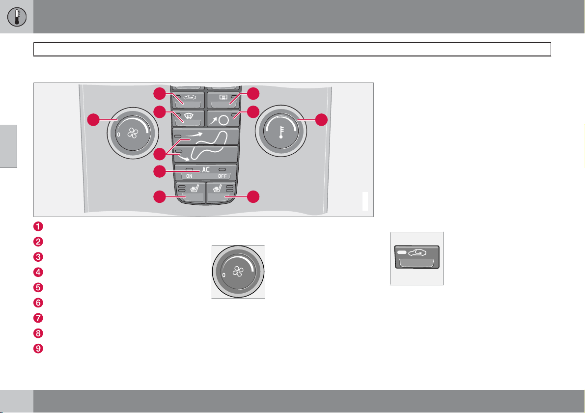
03 Climate control
Manual climate control, AC
Control panel
03
2
3
1 9
4
5
6
Fan
Recirculation
Defroster
Air distribution
AC ON/OFF – Air conditioning On/Off
Heated front left seat
Heated front right seat
Rear window and door mirror defrosters
Temperature
8
4
7
Functions
1. Fan
Increase or decrease the fan
speed by turning the knob.
If the knob is turned anticlockwise and the fan indicator in
the display goes out, the fan
switched off. The display shows the fan symbol
OFF.
and
and the air conditioning are
G026308
2. Recirculation
Recirculation can be used to
shut out bad air, exhaust
fumes, etc. from the passenger compartment. The air in
the passenger compartment
is recirculated. No outside air
is taken into the car. Recirculation (together with the air conditioning system) cools the passenger compartment more
quickly in hot weather. If the air in the car recirculates for too long then there is a risk of the
windows misting.
84
Page 86
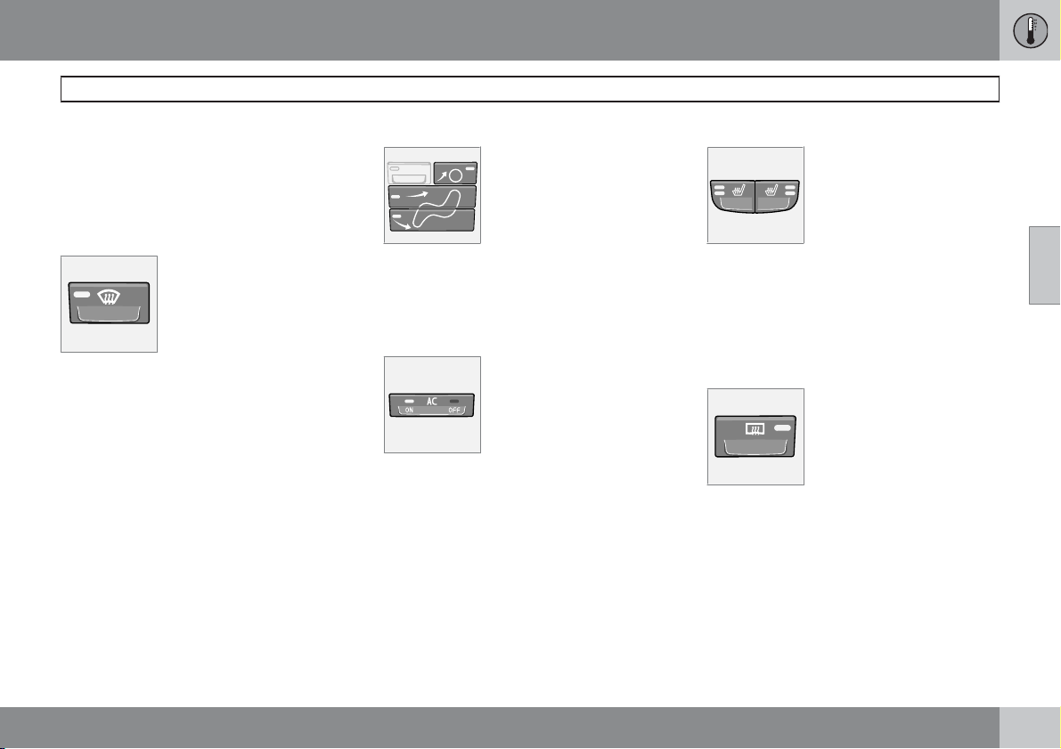
03 Climate control
Manual climate control, AC
Timer
The timer function reduces the risk of icing,
misting and bad air (if recirculation is selected).
See page 74, for activating/deactivating the
function. When the Defroster (3) program is
selected, recirculation is deactivated.
3. Defroster
Used to quickly remove misting and ice from the windscreen and side windows. Air
flows to the windows at high
fan speed. The light in the
defroster button illuminates
when the function is active.
The following also takes place when the
defroster function is activated in order to provide maximum dehumidification in the passenger compartment:
the air conditioning (AC) is automatically
•
switched on (can be switched off with the
AC button (5)
recirculation is automatically disengaged.
•
When the defroster is switched off the climate
control returns to the previous settings.
4. Air distribution
The airflow can be distributed
to the windows, dashboard
vents or floor by pressing the
air distribution buttons.
A symbol on the display
above the climate control
panel and an illuminated light in the relevant
button indicate which function has been
selected.
Refer to the table on page 91.
5. AC – On/Off
ON: The air conditioning is on.
It is controlled by the system's
AUTO function. This way,
incoming air is cooled and
dehumidified.
OFF: The air conditioning is
off.
When the defroster function is activated the air
conditioning is automatically switched on (can
be switched off with the AC button). A symbol
above ON or the climate control panel respectively and an illuminated light in the relevant
button indicate which function has been
selected.
6. and 7. Heated front seats
(option in certain markets)
Higher heat:
– Press the button once – both
lights illuminate.
Lower heat:
– Press the button once – one light illuminates.
Heat off:
– Press the button three times – light not illuminated.
8. Rear window and door mirror
defrosters
Heating is used to quickly
remove misting and ice from
the rear window and door mirrors. Press the button once to
start simultaneous rear window and rearview mirror
defrosting. The function is
active if one lamp is illuminated in the button.
The function is switched off manually or automatically. Switch off manually with one press
on the button. Automatic switching off disconnects the rear window and door mirrors after
12 – 20 minutes depending on outside temperature.
03
``
85
Page 87
03 Climate control
Manual climate control, AC
During cold weather the defrosting also continues after 20 minutes in order to keep the rear
window and door mirrors free of ice and mist.
The intensity of the defrosting can be adapted to the outside temperature. This function
must be switched off manually.
03
9. Temperature
Select cooling or heating for
both driver and passenger
side.
1
1
Depending on market and options selected
86
Page 88
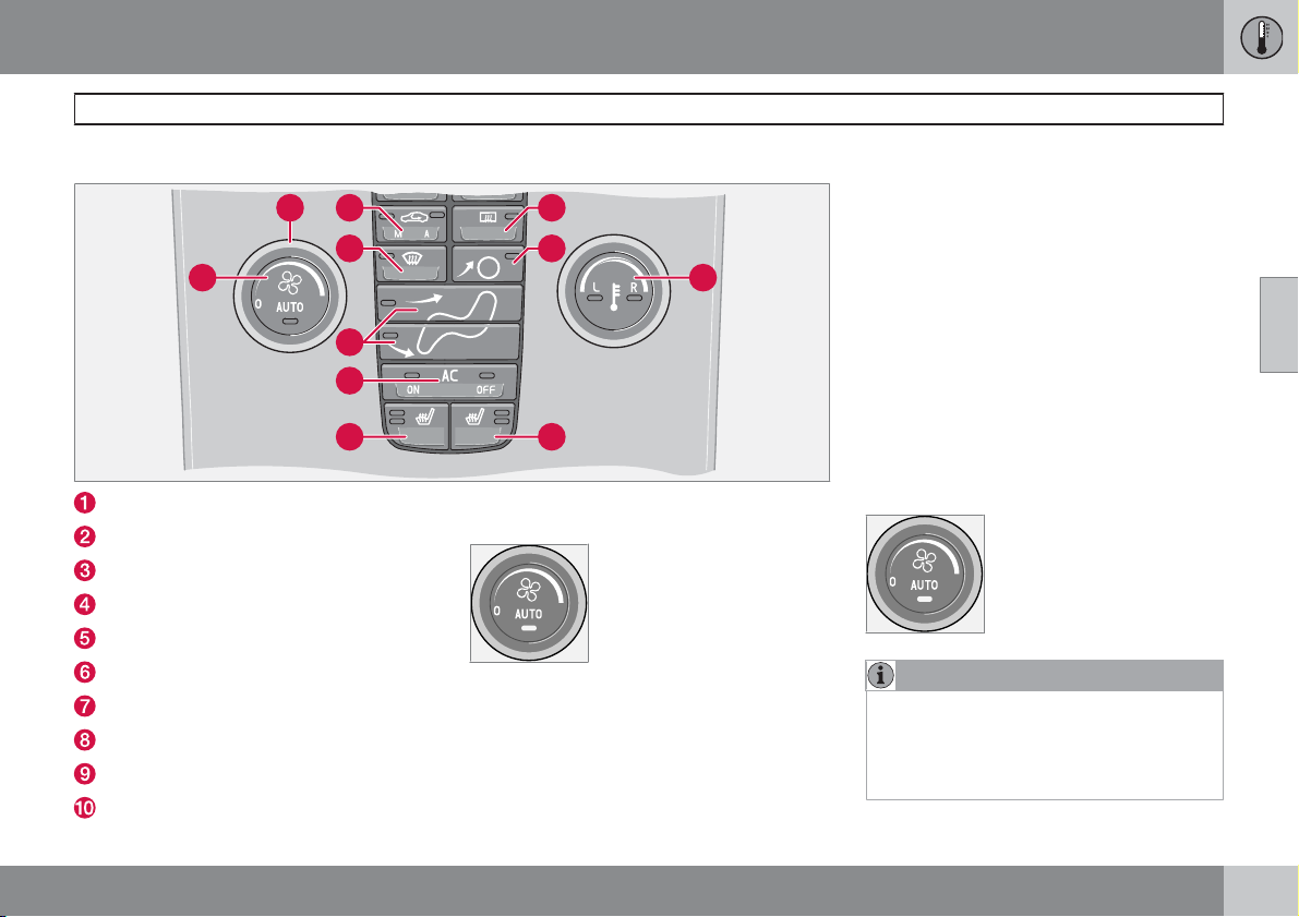
Control panel
03 Climate control
Electronic climate control, ECC*
3
2
4
1 10
5
6
7
AUTO
Fan
Recirculation/Air quality system
Defroster
Air distribution
AC ON/OFF – Air conditioning On/Off
Heated front left seat
Heated front right seat
Rear window and door mirror defrosters
Temperature selector
9
5
8
Functions
1. AUTO
The AUTO function automat-
ically regulates climate con-
trol and maintains the
selected temperature. The
AUTO function controls heat-
ing, air conditioning, fan
speed, recirculation, and air
distribution.
If you select one or more manual functions, the
other functions continue to be controlled automatically. All manual settings are switched off
when AUTO is switched on. The display shows
AUTO CLIMATE.
03
G026309
2. Fan
Turn the knob to increase or
decrease fan speed. If AUTO
is selected then fan speed is
regulated automatically. The
previously set fan speed is
disengaged.
NOTE
If the knob is turned anticlockwise and the
fan indicator in the display goes out, the fan
and the air conditioning are switched off.
The display shows the fan symbol and
OFF.
``
* Option/accessory, for more information, see Introduction.
87
Page 89
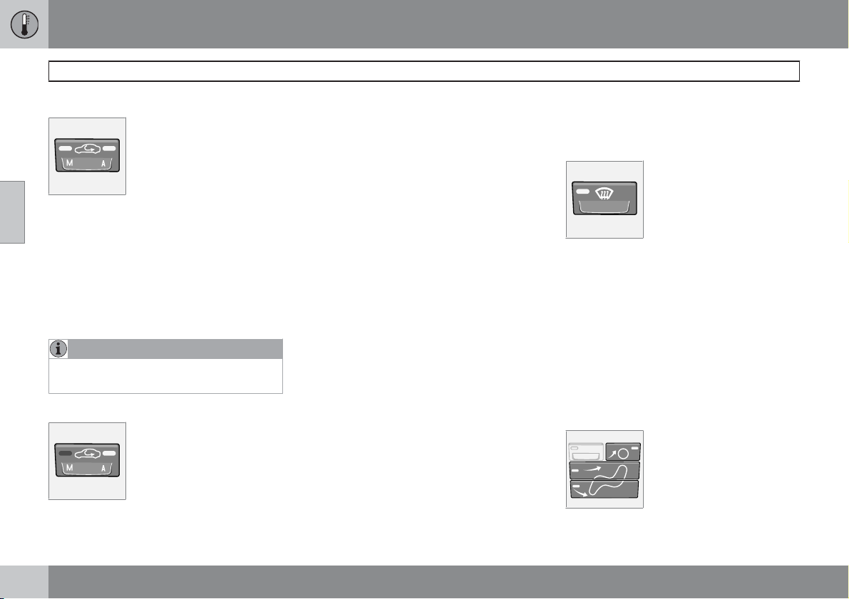
03 Climate control
Electronic climate control, ECC*
3. Recirculation
The function is selected to
shut out bad air, exhaust
gases etc. from the passenger compartment. The air in
the passenger compartment
03
this function is activated. If the air in the car
recirculates for too long, there is a risk of misting on the insides of the windows.
is recirculated, i.e. no outside
air is taken into the car when
Timer
The timer function reduces the risk of icing,
misting and bad air (if recirculation is selected).
To activate/deactivate the function see
page 74.
NOTE
When Defroster (4) is selected, recirculation
is always deactivated.
3. Air quality system (option)
(same button as recirculation)
G000000
The air quality system consists of a multi-filter
and a sensor. The filter separates gases and
particles to reduce the levels of odours and
pollution in the passenger compartment. When
the sensor detects polluted outside air, the air
intakes are closed and the air in the passenger
compartment is recirculated. A green light (A)
illuminates in the button when the air quality
sensor is active.
Activating the air quality sensor:
±
Press AUTO (1) to activate the air quality
sensor (normal setting).
Or:
±
Switch between three functions by pressing repeatedly the recirculation button.
Air quality sensor engaged – the light (A)
•
illuminates.
No recirculation engaged, provided it is not
•
required for cooling in hot weather – light
not illuminated.
Recirculation engaged – the light (M) illu-
•
minates.
Keep the following in mind:
As a rule, the air quality sensor should
•
always be engaged.
Recirculation is limited in cold weather to
•
avoid misting.
The defroster functions for the front, side
•
and rear windows can be used to demist
the windows.
4. Defroster
Used to quickly remove misting and ice from the windscreen and side windows. Air
flows to the windows at high
fan speed. The light in the
defroster button illuminates
when the function is active.
The following also takes place when the
defroster function is activated in order to provide maximum dehumidification in the passenger compartment:
the air conditioning (AC) is automatically
•
switched on (can be switched off with the
AC button (6)
recirculation is automatically disengaged.
•
When the defroster is switched off the climate
control returns to the previous settings.
5. Air distribution
The airflow can be distributed
to the windows, dashboard
vents or floor by pressing the
air distribution buttons.
88
* Option/accessory, for more information, see Introduction.
Page 90
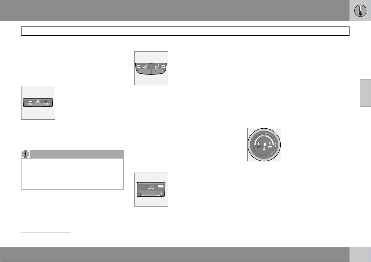
03 Climate control
Electronic climate control, ECC*
A symbol on the display above the climate control panel and an illuminated light in the relevant
button indicate which function has been
selected.
Refer to the table on page 91.
6. AC – On/Off (ON/OFF)
ON: The air conditioning is on.
It is controlled by the system's
AUTO function. This way,
incoming air is cooled and
dehumidified.
OFF: Off
When the defroster function is activated the air
conditioning is automatically switched on (can
be switched off with the AC button).
NOTE
The climate control system's demisting
function with humidity sensor is significantly
reduced with the air conditioning in deactivated mode (OFF), as well as with manually
selected air distribution and fan speed.
7 and 8. Heated front seats*
To activate front seat heating:
Higher heat:
±
Press the button once – both lights illuminate.
Lower heat:
±
Press the button once – one light illuminates.
Heat off:
±
Press the button three times – light not illuminated.
9. Rear window and door mirror
defrosters
Heating is used to quickly
remove misting and ice from
the rear window and door mir-
rors. Press the button once to
start simultaneous rear win-
dow and rearview mirror
active if one lamp is illuminated in the button.
defrosting. The function is
The function is switched off manually or automatically. Switch off manually with one press
on the button. Automatic switching off disconnects the rear window and door mirrors after
12 – 20 minutes depending on outside temperature.
1
During cold weather the defrosting
tinues after 20 minutes in order to keep the rear
window and door mirrors free of ice and mist.
The intensity of the defrosting can be adapted
to the outside temperature. This function must
be switched off manually.
also con-
10. Temperature selector
The temperatures on the
driver and passenger sides
can be set independently.
Press the button once to activate one side only. Press
side. Press the button a third time to activate
both sides.
The active side is indicated by the button's light
and in the display above the climate control
panel.
When the car is started, the most recent setting
is resumed.
again to activate the other
03
1
Depending on market
* Option/accessory, for more information, see Introduction.
``
89
Page 91
03
03 Climate control
Electronic climate control, ECC*
NOTE
Heating or cooling cannot be hastened by
selecting a higher or lower temperature than
the actual desired temperature.
90
* Option/accessory, for more information, see Introduction.
Page 92
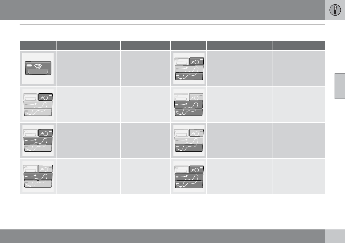
03 Climate control
Air distribution
Air distribution Use: Air distribution Use:
Air to windows. Some air
flows from the air vents. The
air is not recirculated. Air
conditioning is always
engaged.
To remove ice and
misting quickly.
Air to the floor and windows.
Some air flows from the dashboard air vents.
To ensure comfortable
conditions and good
demisting in cold or
humid weather.
03
Air to windscreen and side
windows. Some air flows
from the air vents.
Airflow to windows and from
dashboard air vents.
Airflow to the head and
chest from the dashboard
air vents.
To prevent misting
and icing in a cold and
humid climate. (Not
for low fan speed.)
To ensure good comfort in warm, dry
weather.
To ensure efficient
cooling in warm
weather.
Air to floor and from dashboard air vents.
Air to floor. Some air flows to
the dashboard air vents and
windows.
Airflow to windows, from
dashboard air vents and to
the floor.
In sunny weather with
cool outside temperatures.
To warm the feet.
To provide cooler air
for the feet or warmer
air to the upper body in
cold weather or hot,
dry weather.
91
Page 93
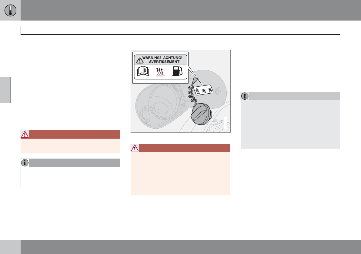
03 Climate control
Fuel-driven engine block heater and passenger compartment heater*
General information about heaters
The parking heater heats the engine and passenger compartment and can be started
directly or with the timer.
Two different times can be selected using the
timer. Here, time refers to the time when the car
03
is heated and ready. The car's electronic system calculates when heating should be started
based on the outside temperature.
The heater is cannot start if the outside temperature exceeds 25 °C. At –10 °C or lower the
maximum running time of the parking heater is
50 minutes.
WARNING
The car must be outdoors when the petrol
or diesel heater is used.
NOTE
When the parking heater is active there may
be smoke from underneath the car, which is
perfectly normal.
Refuelling
Warning decal on fuel filler flap.
WARNING
Fuel which spills out could be ignited.
Switch off the fuel-driven heater before starting to refuel.
Check on the information display that the
parking heater is switched off. When it is
running, the information display shows
PARK HEAT ON.
Parking on a hill
If the car is parked on a steep hill, the front of
the car should point downhill to ensure that
there is a supply of fuel to the parking heater.
Battery and fuel
If the battery has insufficient charge or the fuel
level is too low, the parking heater is switched
off automatically and a message appears on
the information display.
±
Acknowledge the message by pressing the
indicator stalk READ button once.
IMPORTANT
Repeated use of the parking heater combined with short journeys may discharge the
battery and impair starting.
The car should be driven for the same time
G007632
as the heater is used to ensure that the car's
battery is recharged adequately to replace
the energy consumed by the heater when it
is used on a regular basis.
92
* Option/accessory, for more information, see Introduction.
Page 94
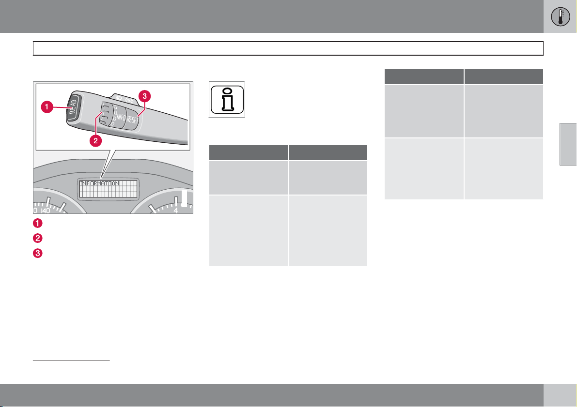
03 Climate control
Fuel-driven engine block heater and passenger compartment heater*
Activating the heater
READ button
Thumbwheel
RESET button
1
1
Symbols and display messages
When one of the timer's settings or
DIRECT START is activated, the
information symbol in the combined instrument panel illuminates
an explanatory text.
and the information display shows
Display Specification
FUEL HEATER ON
TIMER IS SET FOR
G029052
FUEL HEATER
The heater is
switched on and
running.
Reminder that the
heater will start at
the set time after the
car has been left,
when the ignition
key is removed from
the ignition switch.
Display Specification
HEATER STOPPED - LOW BATTERY
HEATER STOPPED LOW FUEL
LEVEL
The heater has been
stopped by the car's
electronics in order
to facilitate starting
the engine.
The heater has been
stopped by the car's
electronics in order
to facilitate starting
the engine as well as
50 km driving.
Direct start and immediate stop
1.
Scroll with the thumbwheel to DIRECT
.
START
2.
Press the RESET button to select between
ON and OFF.
ON: Parking heater switched on manually or
with programmed timer.
OFF: Parking heater switched off.
With the direct start of the heater it will be activated for 50 minutes.
03
1
No function in cars without trip computer, fuel-driven parking heater as well as stability and traction control system.
* Option/accessory, for more information, see Introduction.
``
93
Page 95
03 Climate control
Fuel-driven engine block heater and passenger compartment heater*
Heating of the passenger compartment will
begin as soon as the engine coolant has
reached the correct temperature.
NOTE
03
The car can be started and driven while the
parking heater is running.
Setting the timer
The time when the car shall be used and heated
is specified with the timer.
Select between
1.
Scroll with the thumbwheel to
HEAT TIMER 1
2.
Briefly press the RESET button so that the
hours setting starts to flash.
3. Select the required hour using the thumbwheel.
4.
Briefly press RESET to move to the flashing minutes setting.
5. Select the required minute using the
thumbwheel.
6.
Briefly press RESET to confirm the setting.
7.
Press RESET to activate the timer.
TIMER 1 and TIMER 2.
.
PARK
After setting
be programmed with
the thumbwheel.
Set the alternative time in the same way as
TIMER 1.
TIMER 1 a second start time can
TIMER 2 by scrolling with
Deactivating a timer-started heater
A timer-started heater can be switched off
manually before the set time has elapsed. Proceed as follows:
1.
Press the READ button.
2. Use the thumbwheel to scroll to the text
PARK HEAT TIMER 1 or PARK HEAT
TIMER 2
The text
3.
Press RESET.
The text
glow and the heater is switched OFF.
A timer-started heater can be switched off in
accordance with the instructions in the section
"Direct start and immediate stop".
.
ON flashes on the display.
OFF is shown with a constant
Clock/timer
The heater's time is connected to the car's
clock.
NOTE
All timer programming will be cleared if the
car's clock is reset.
94
* Option/accessory, for more information, see Introduction.
Page 96
Auxiliary heater (diesel)
In diesel-engined cars the auxiliary heater may
be required for achieving the correct temperature in the passenger compartment during cold
weather.
The heater starts automatically when extra
heat is required when the engine is running.
The heater is switched off automatically when
the correct temperature is reached or when the
engine is switched off.
NOTE
The auxiliary heater cannot be switched on
or off manually but is only controlled by the
car's electronics.
When the auxiliary heater is active there may
be smoke from underneath the car, which is
perfectly normal.
03 Climate control
Fuel-driven auxiliary heater* (diesel)
03
* Option/accessory, for more information, see Introduction.
95
Page 97

96
Front seats.............................................................................................. 98
Interior lighting...................................................................................... 100
Storage spaces in the passenger compartment................................... 102
Rear seat............................................................................................... 106
Cargo area............................................................................................ 108
G020908
Page 98
INTERIOR
04
Page 99
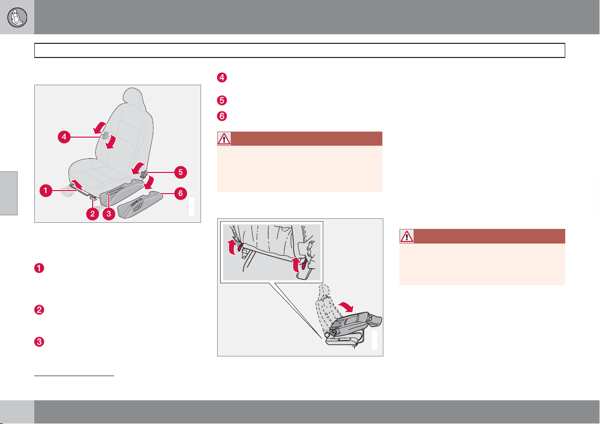
04 Interior
Front seats
Seating position
04
The driver's and passenger seats can be
adjusted to the optimum sitting and driving
positions.
Forward/backward: lift the handle to adjust
the distance to the steering wheel and pedals. Check that the seat is locked after
changing position.
Raise/lower the front of the seat cushion
(driver's and passenger seat*), pump up/
down.
Raise/lower the seat (driver's and passenger seat*), pump up/down.
Lumbar support 1 (driver's and passenger
seat*), turn the wheel.
Backrest rake: turn the wheel.
Control panel for power seat*.
WARNING
Adjust the position of the driver's seat and
adjust the seatbelt, see page 16, before setting off, never while driving.
Check that the seat is locked in position.
Tipping the front seat backrest*
G027960
The passenger seat backrest can be folded
forward to make room for long loads.
1. Move the seat as far back as possible.
2. Adjust the backrest to an upright position
90 degrees.
3. Lift the catches on the rear of the backrest
while folding it forwards.
4. Push the seat forward so that the head
restraint "locks" in under the glovebox.
Floor mats*
Volvo supplies floor carpets which are especially produced for your car.
WARNING
The floor mat at the driver's seat must be
firmly fitted and secured in the attachment
clips to prevent it from being trapped
around and under the pedals.
G014805
1
Also applies to power seat.
98
* Option/accessory, for more information, see Introduction.
Page 100
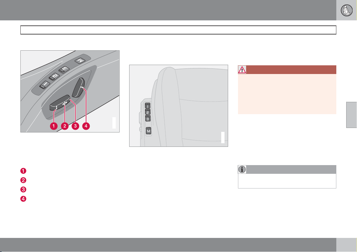
04 Interior
Front seats
Power seat*
The seats can be adjusted for a certain time
after unlocking the door with the remote control without the key being inserted into the ignition switch. The seat can always be adjusted in
ignition position I or II.
Front edge of seat cushion up/down
Seat, forwards/backwards
Seat, up/down
Backrest rake
An overload protection is deployed if one of the
seats is blocked. If this happens, turn off the
ignition and wait a short time before adjusting
the seat again. Only one of the seat's settings
can be adjusted at a time.
Memory function
G020199
Buttons for memory function.
Store setting
1. Adjust seat.
2.
Press and hold button M while pressing
button 1, 2 or 3 simultaneously.
Using a stored setting
Press one of the memory buttons 1–3 until the
seat stops. If you release the button then the
movement of the seat will stop.
Emergency stop
If the seat accidentally begins to move, press
any of the buttons to stop the function.
WARNING
Risk of crushing. Make sure that children do
not play with the controls.
Check that there are no objects in front of,
behind or under the seat during adjustment.
Ensure that none of the rear seat passengers is in danger of becoming trapped.
Memory in the remote control
The settings for the driver's seat are stored in
the memory for the remote control with which
the car is locked. When the car is unlocked with
G020200
the same remote control the driver's seat
adopts the stored settings when the driver's
door is opened.
NOTE
Remote control memory is independent of
seat memory.
04
* Option/accessory, for more information, see Introduction.
99
 Loading...