

Page 1
Page 2

Page 3

Contents
Driver Information Display ............................................................... 1
STALK SWITCH CONTROL LEVER .............................................. 1
Stalk Switch Functions ..................................................................... 2
Selecting a Menu .............................................................................. 2
Changing Settings ............................................................................ 4
BASIC LEVEL INSTRUMENT CLUSTER DID ............................. 5
Digital Gauges .................................................................................. 7
1. Outside Temperature ................................................................. 7
2. Distance to Destination ............................................................. 7
Display Settings ............................................................................... 7
1. Contrast ..................................................................................... 7
2. Backlight ................................................................................... 7
Time/Date ...................................................................................... 7
Setup ................................................................................................. 8
1. Language ................................................................................... 8
2. Distance ..................................................................................... 8
3. Temperature ............................................................................... 8
Aftertreatment .................................................................................. 9
MID-LEVEL AND HIGH-LEVEL INSTRUMENT CLUSTER
DID ................................................................................................... 14
Mid-Level and High-Level DID Menus ......................................... 16
Driving Menus ............................................................................. 16
Digital Gauges in the DID (High and Mid Level Cluster Only) . 17
1. Current Gear Position (Automated Transmission) .................. 18
2. Outside Temperature ............................................................... 19
3. Engine Oil Temperature .......................................................... 20
4. Transmission Oil Temperature ................................................ 21
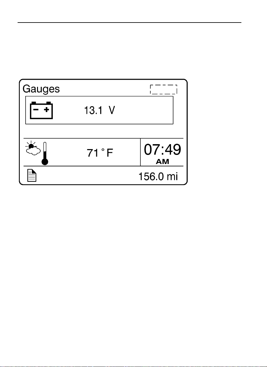
5. Battery Voltage ........................................................................ 22
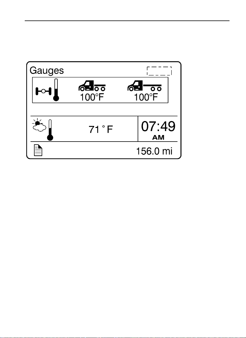
6. Front and Rear Axle Temperature ........................................... 23
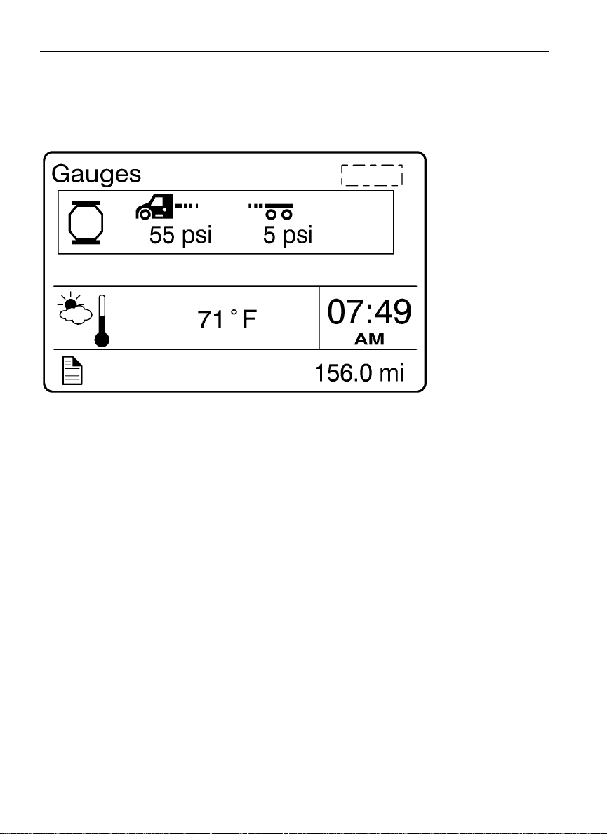
7. Front and Rear Suspension Pressure ....................................... 24
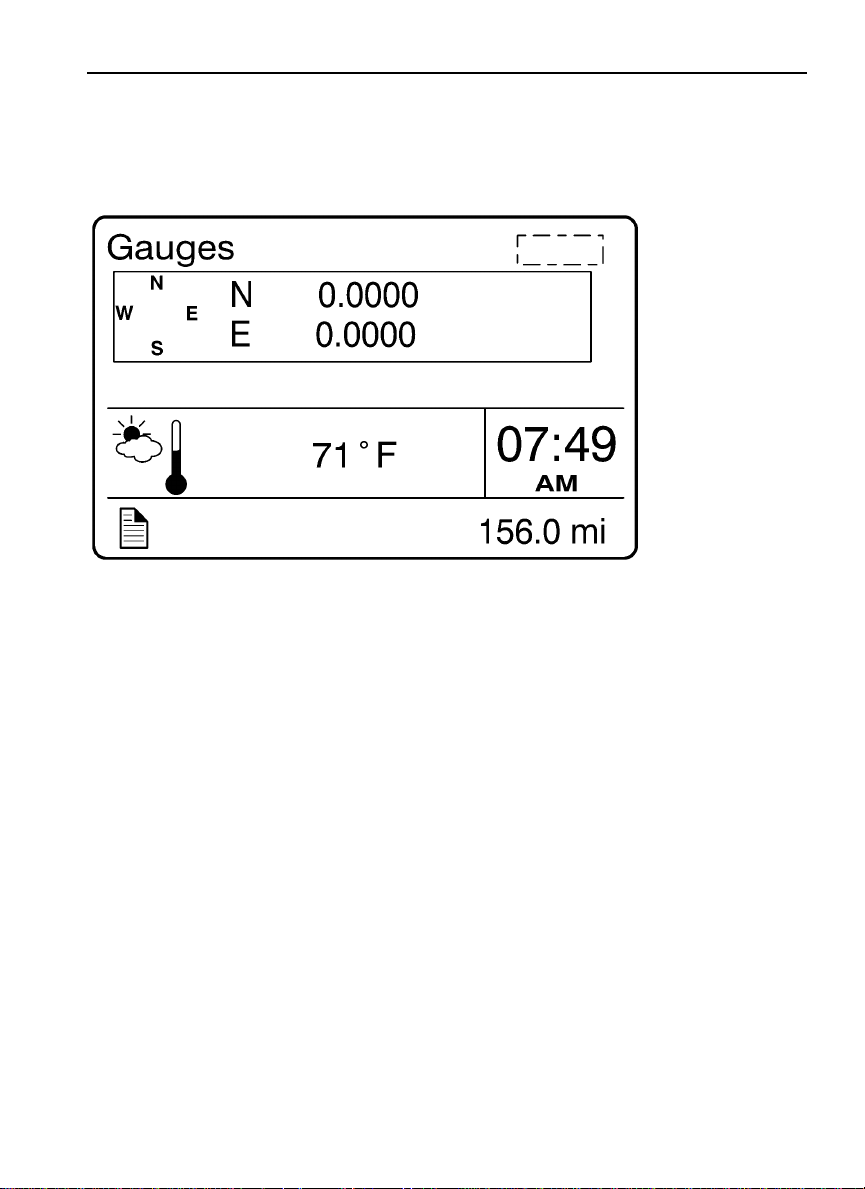
8. Volvo Link Compass ............................................................... 25
Fuel Data ...................................................................................... 25
1. Instantaneous Gallons Per hour ............................................... 26
2. Trip Fuel Used ......................................................................... 27
3. Distance to Empty ................................................................... 28
4. Fuel Economy ......................................................................... 29
Page 4

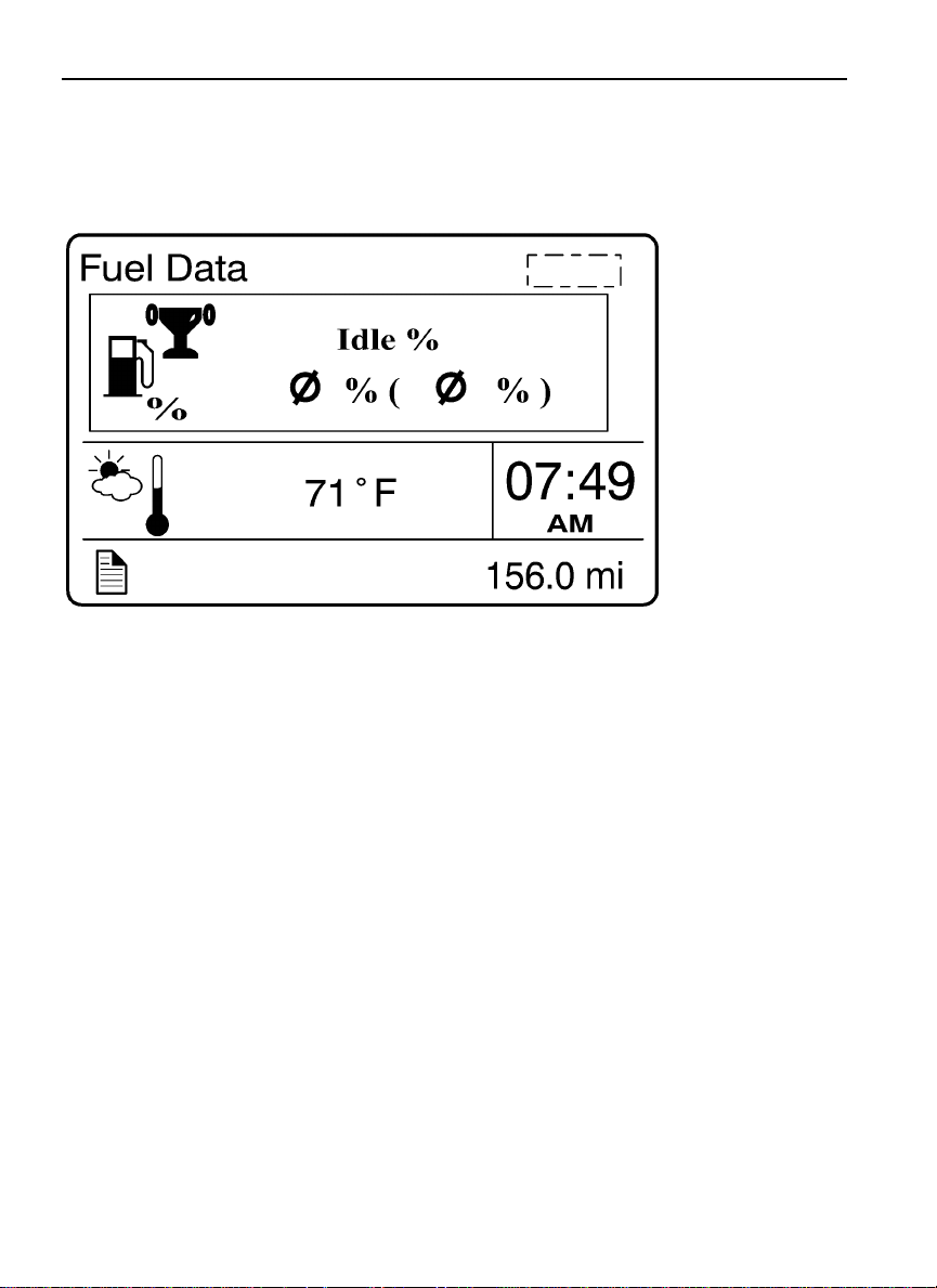
5. Idle Percent .............................................................................. 30
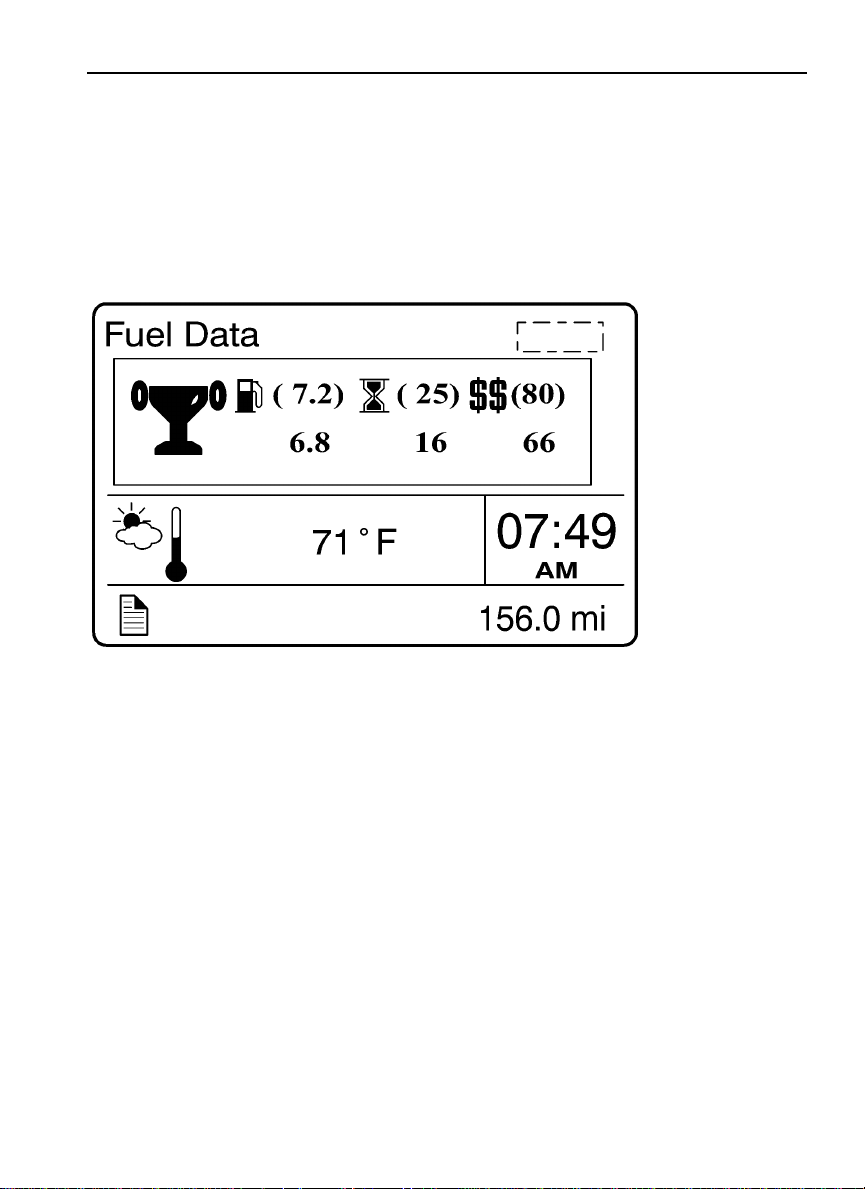
6. Sweet Spot/Performance Bonus .............................................. 31
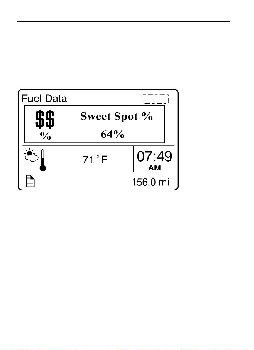
7. Sweet Spot Percentage ............................................................ 32
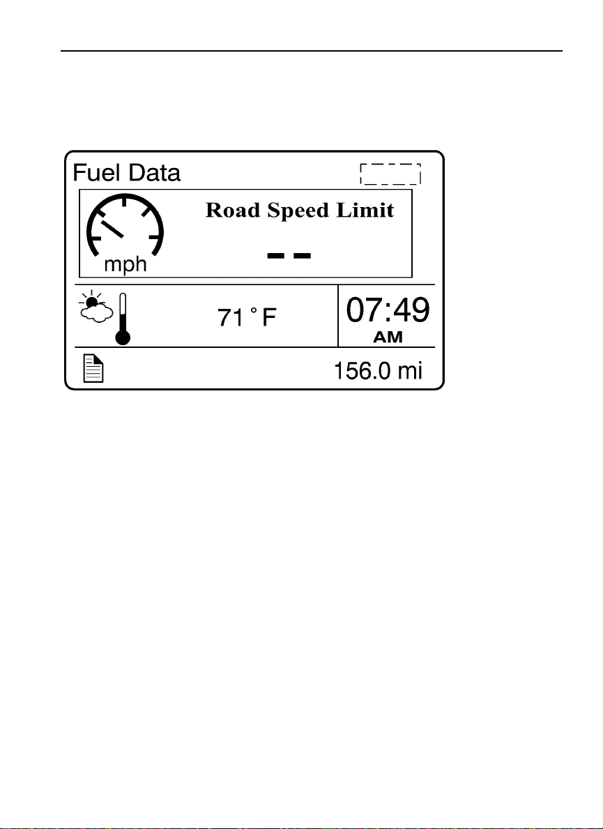
8. Road Speed Limit .................................................................... 33
Time/Distance .............................................................................. 34
1. Time and Date ......................................................................... 34
2. Alarm Clock ............................................................................ 35
3. Distance to Destination ........................................................... 36
4. Trip Average Speed ................................................................. 37
5. Estimated Time of Arrival (ETA) ............................................ 38
Aftertreatment .............................................................................. 39
Aftertreatment Status ................................................................... 40
Volvo Link ................................................................................... 48
Display ......................................................................................... 49
1. Black Panel .............................................................................. 49
2. Favorite Display ...................................................................... 50
3. Backlight ................................................................................. 51
4. Favorite Display Setting .......................................................... 52
5. Night/Day ................................................................................ 52
Vehicle Messages ......................................................................... 52
Reset ............................................................................................ 55
Non-Driving/Stationary Menu ..................................................... 56
Display Setting ............................................................................ 59
1. Language ................................................................................. 60
2. Units ........................................................................................ 61
4. Display Light ........................................................................... 63
5. Change Password .................................................................... 65
Vehicle Settings ........................................................................... 66
1. Fleet Limits ............................................................................. 66
2. Fleet ID .................................................................................... 70
3. Drain Water in Fuel (if equipped) ........................................... 71
Diagnostics .................................................................................. 71
1. Fault Diagnostics ..................................................................... 72
2. Cluster Self Test ...................................................................... 72
3. Part Number ............................................................................ 73
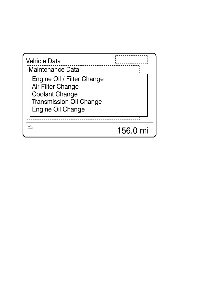
Vehicle Data ................................................................................. 76
1. Oil Level (Volvo engines only) ............................................... 76
2. Maintenance Data .................................................................... 77
Page 5

Datalog ......................................................................................... 78
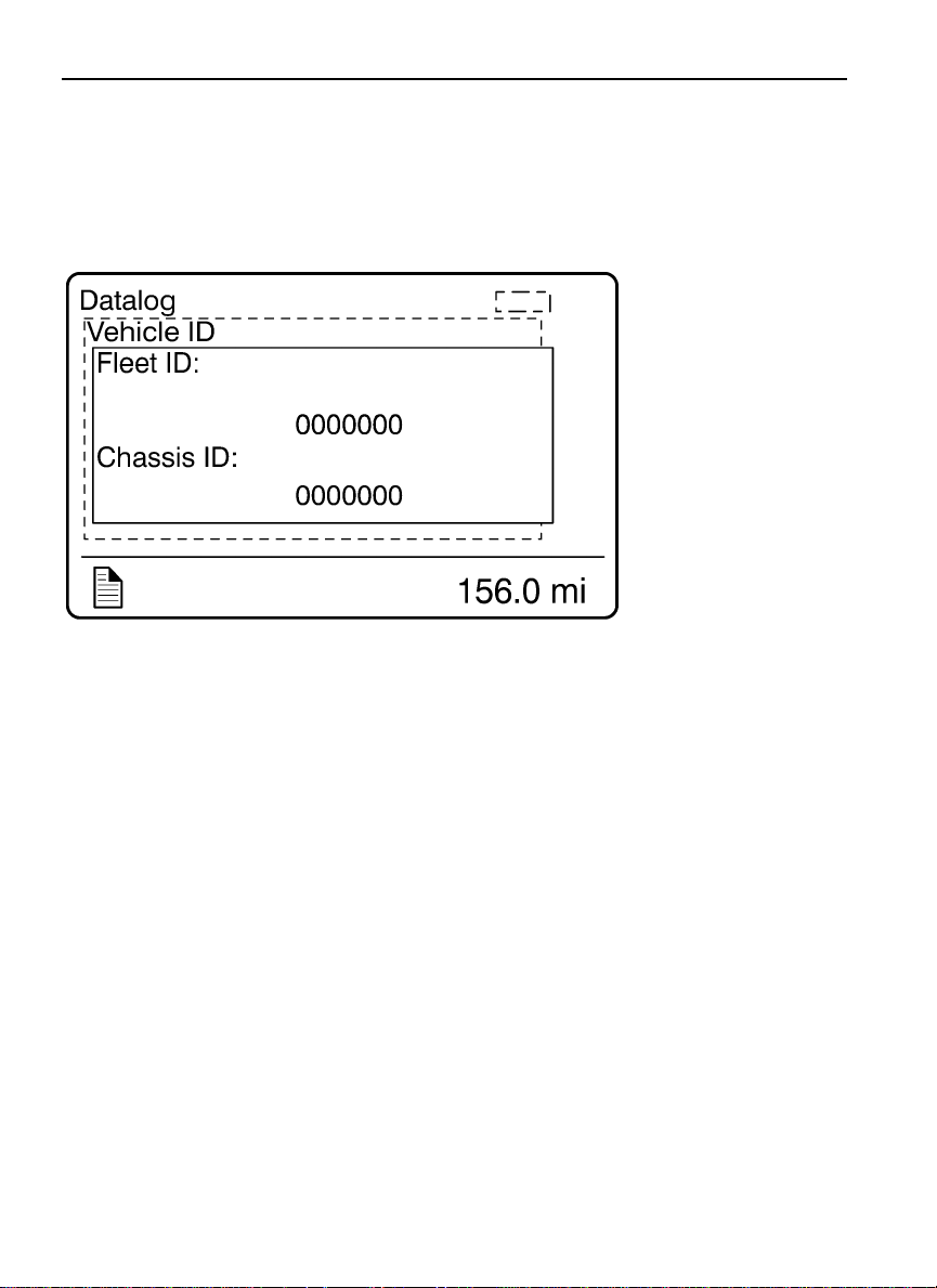
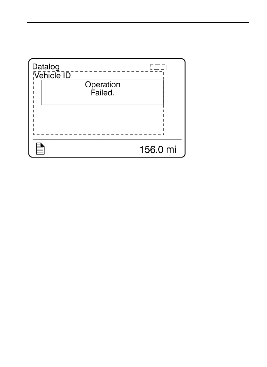
1. Vehicle ID ................................................................................ 78
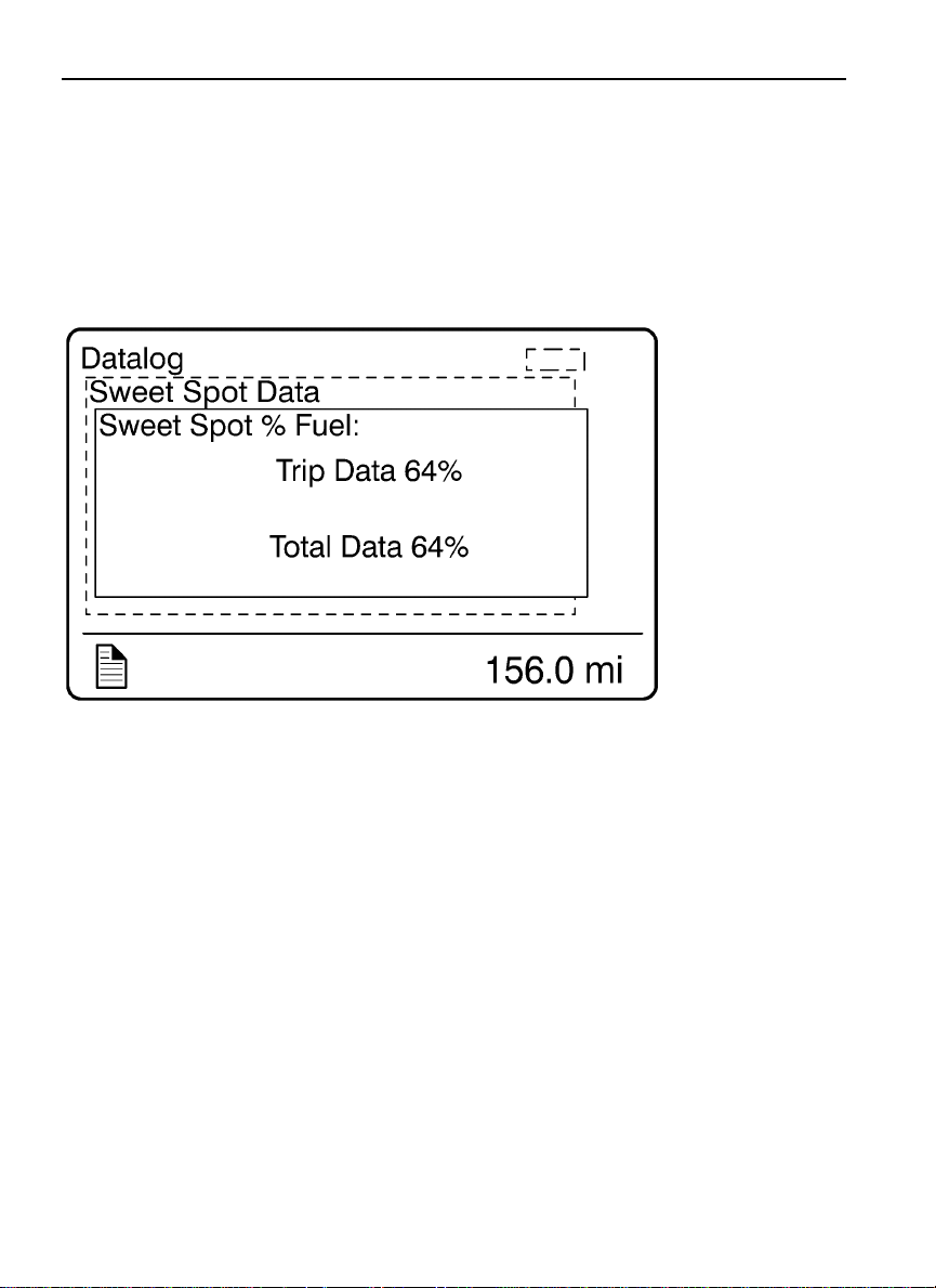
2. Sweet Spot Data ...................................................................... 80
3. Total Data ................................................................................ 81
4. Trip Data .................................................................................. 82
5. Reset Trip Data ........................................................................ 87
Pre-Trip Assistance ..................................................................... 89
Volvo Enhanced Cruise (VEC) .................................................... 97
Tire Pressure System ................................................................. 101
Password .................................................................................... 101
1. Password ................................................................................ 101
DISPLAY SYMBOLS ................................................................. 104
Alarm, Check and Information Symbols ................................... 104
STATUS SYMBOLS ................................................................... 109
Other Symbols ........................................................................... 110
MESSAGES ................................................................................. 111
General ....................................................................................... 111
Stop Message ............................................................................. 111
Warning Message ....................................................................... 112
Information Message ................................................................. 113
Stop, Check, Info Symbols and Associated Icons ..................... 114
Acknowledging Messages ......................................................... 116
Examples of Fault Symbols and Text ........................................ 116
Page 6

Page 7
Safety Information
IMPORTANT: Before driving this vehicle, be certain that you have read and that you
fully understand each and every step of the driving and handling information in this
manual. Be certain that you fully understand and follow all safety warnings.
IT IS IMPORTANT THAT THE FOLLOWING INFORMATION BE READ,
UNDERSTOOD AND ALWAYS FOLLOWED.
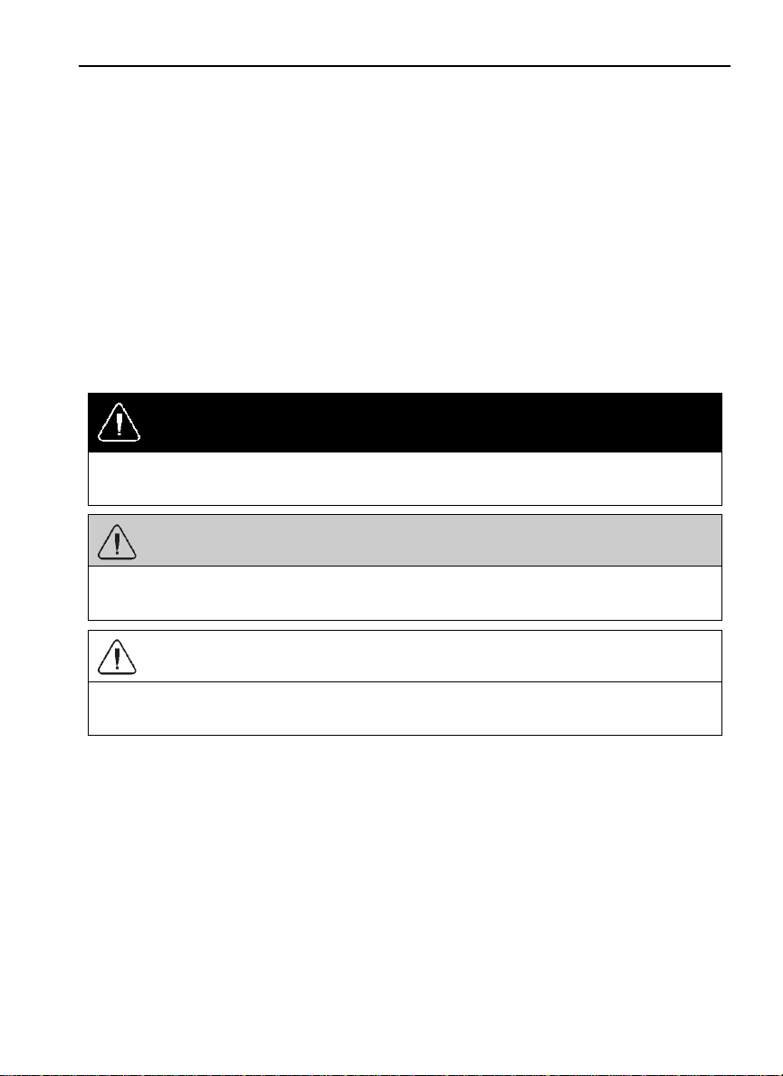
The following types of advisories are used throughout this manual:
DANGER
Danger indicates an unsafe practice that could result in serious personal injury or death.
A danger advisory banner is in white type on a black background with a black border.
WARNING
Warning indicates an unsafe practice that could result in personal injury. A warning
advisory banner is in black type on a gray background with a black border.
CAUTION
Caution indicates an unsafe practice that could result in damage to the product. A caution
advisory is in black type on a white background with a black border.
Note: Note indicates a procedure, practice, or condition that must be followed in order for
the vehicle or component to function in the manner intended.
Labels Danger, Warning, Caution and Advisory labels are placed in various locations of the
vehicle to alert drivers and service technicians about situations that may lead to personal
injury or equipment damage. In the event that a label is damaged or missing the label must
be replaced. Contact your authorized Volvo Truck dealer for assistance regarding labels.
Page 8

Page 9
Driver Information Display 1
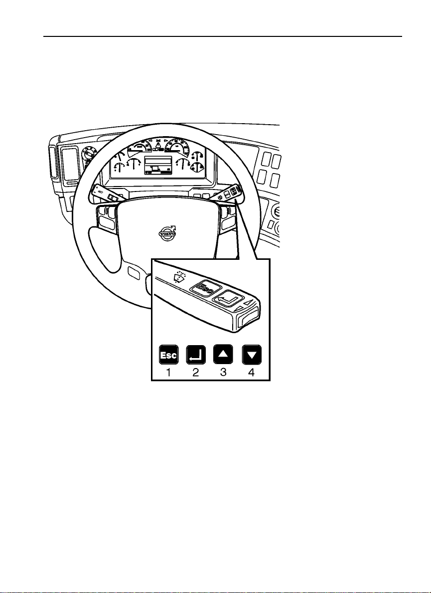
STALK SWITCH CONTROL LEVER
The stalk switch control lever is used to interact with the DID. The lever is located on
the right-hand side of the steering wheel.
W3005262
Page 10
2 Driver Information Display
Stalk Switch Functions
The Esc or Escape button is used to return to the previous menu or display, or to cancel
•
a setting or operation.
The Enter button is used to display a list of menus, open a menu, and select a chosen
•
value.
The Up arrow is used to scroll up through a menu and to increase numerical values.
•
The Down arrow is used to scroll down through a menu and to decrease numerical
•
values.
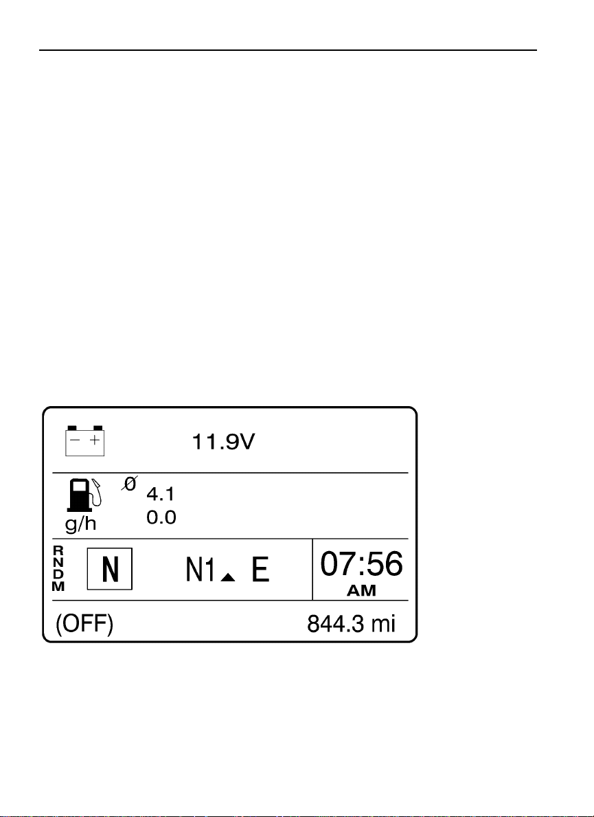
Selecting a Menu
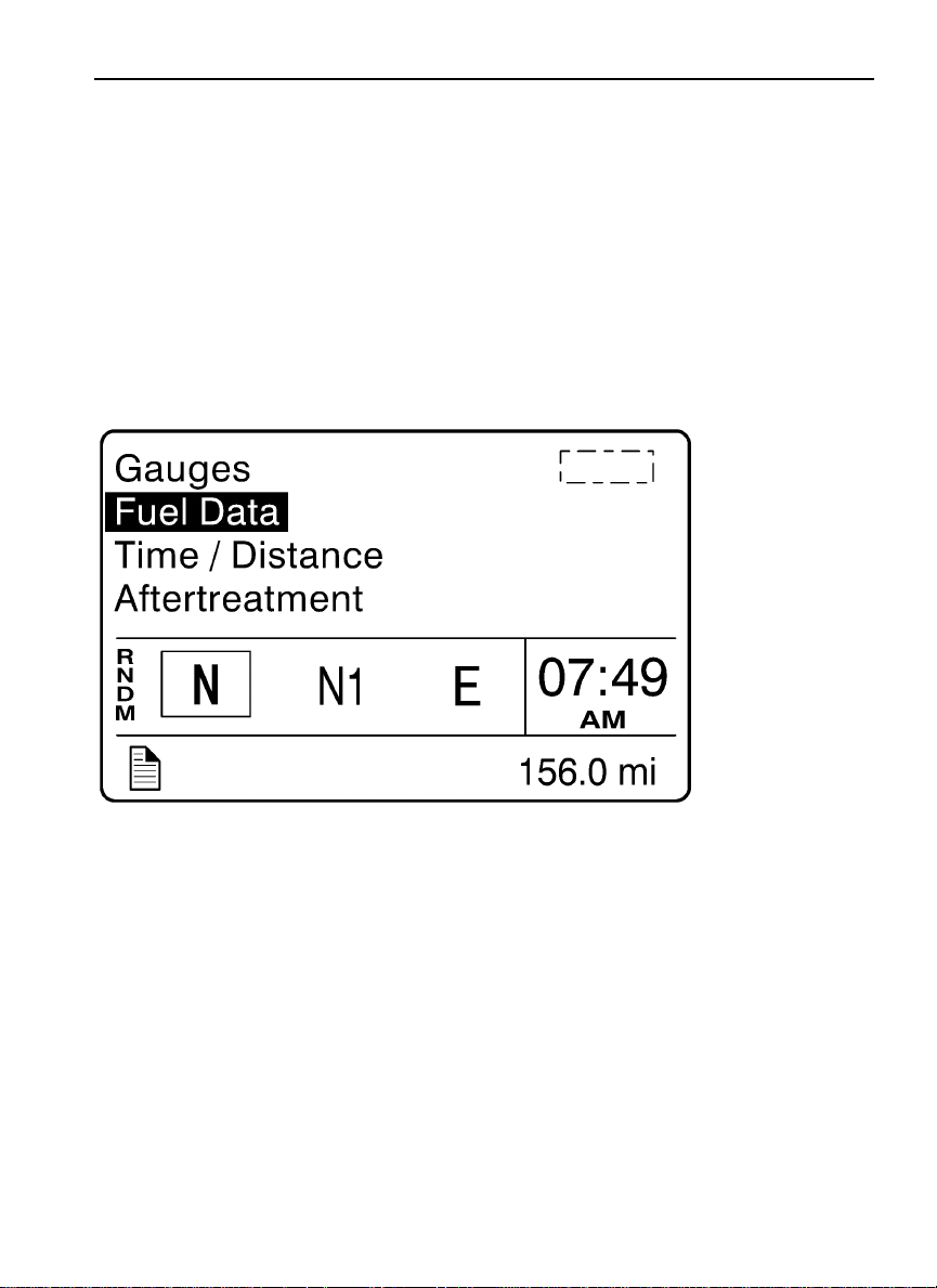
The following drawing is the current condition screen. This is what is displayed when
starting the truck and also while driving.
W3029674
Page 11
Driver Information Display 3
1 Press the Enter button to display the available menus.
2 Use the up and down arrows to scroll through the list of menus.
3 Press the Enter button to open the selected menu.
4 Press the Esc button to return to the previous menu or display, or to cancel a setting
or operation.
W3007351
Page 12
4 Driver Information Display
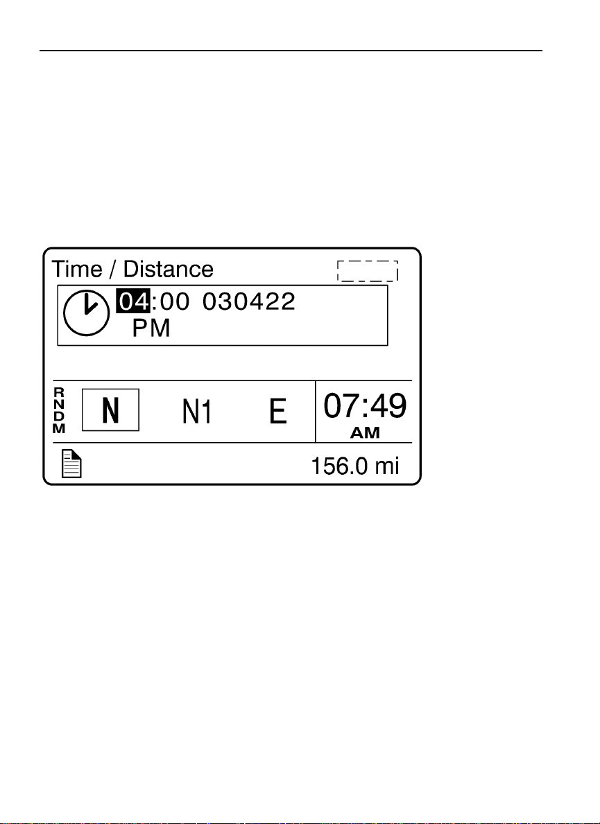
Changing Settings
1 The up and down arrows increase and decrease set values.
2 Press the Enter button to confirm the choice and move to the next position.
3 Press the Escbutton to return to theprevious position, or to cancel a setting or operation.
W3007352
Page 13
Driver Information Display 5
BASIC LEVEL INSTRUMENT CLUSTER DID
The basic Driver Information Display (DID) is located in the center of the basic level
instrument cluster. The DID displays digital gauges, main menus and sub-menus that
provide necessary and important information to the vehicle operator. The information
available to the operator depends on vehicle configuration.
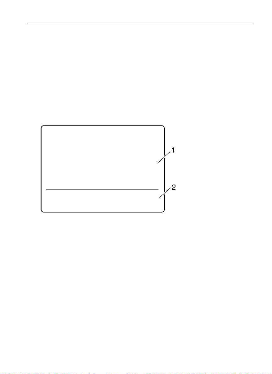
There are two sections of display information in the basic DID:
Top — Menus and gauges
•
Bottom — Odometer
•
The default display is clock and odometer. Press the Enter button to display the menu.
1 Menus and gauges
2 Odometer
W3029664
Page 14

6 Driver Information Display
Note: Depending on vehicle configuration, some menus may not be available.
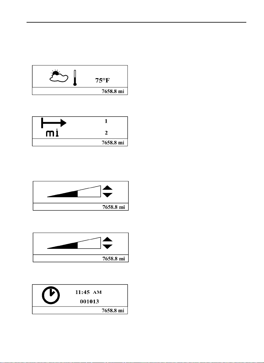
The following menus are available with the basic DID.
Digital Gauges
•
— Outside Temperature
— Distance to Destination
Display Settings
•
— Contrast
— Backlight
Time/Date
•
Aftertreatment
•
— Initiate REGEN
— ATS Status
— Cancel REGEN
Setup
•
— Language
— Distance
— Temperature
Page 15
Digital Gauges
1. Outside Temperature
2. Distance to Destination
Display Settings
1. Contrast
Driver Information Display 7
W3029666
W3029667
2. Backlight
Time/Date
W3029668
W3029669
W3029670
Page 16
8 Driver Information Display
Setup
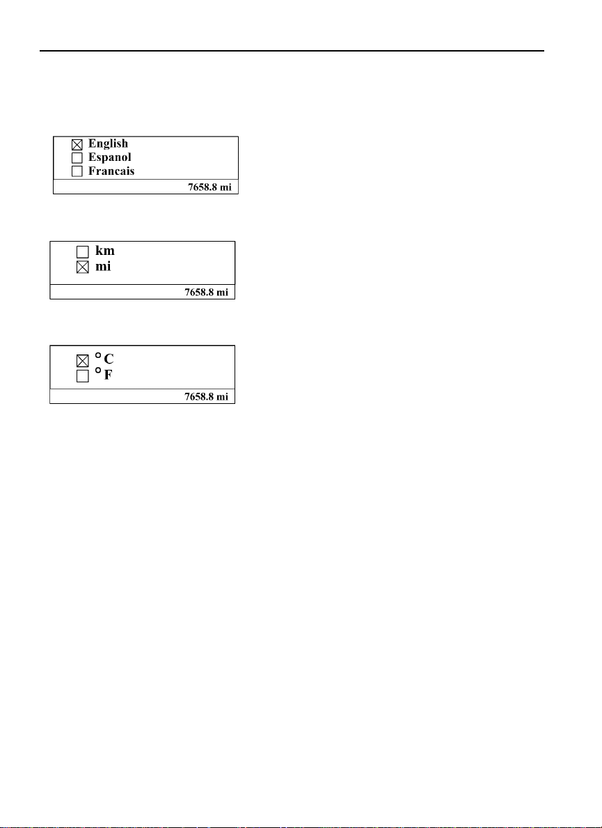
1. Language
W3029671
2. Distance
W3029672
3. Temperature
W3029673
Page 17
Driver Information Display 9
Aftertreatment
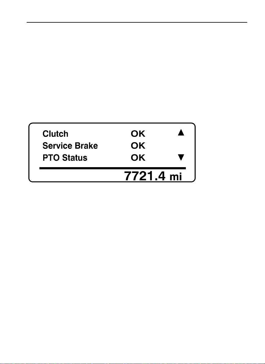
The Aftertreatment status submenus provide information about the conditions required
for performing a regeneration. The status can be OK (regeneration allowed), CHECK
(regeneration not allowed) or N/A (not applicable). When ATS Status is selected, the
following submenus are available.
W3007450
To perform a parked regeneration, the clutch pedal must not be depressed, the service brake
must not be engaged and a PTO must not be engaged or the PTO must be able to operate
above the minimum engine speed required.
Page 18
10 Driver Information Display
W3007449
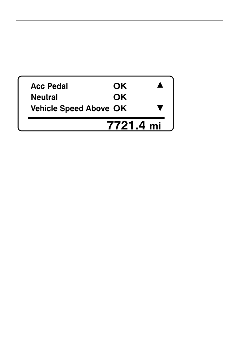
To perform a parked regeneration, the accelerator pedal must not be depressed, the
transmission must be in the neutral position and the vehicle speed must not be above zero.
Page 19
Driver Information Display 11
W3007448
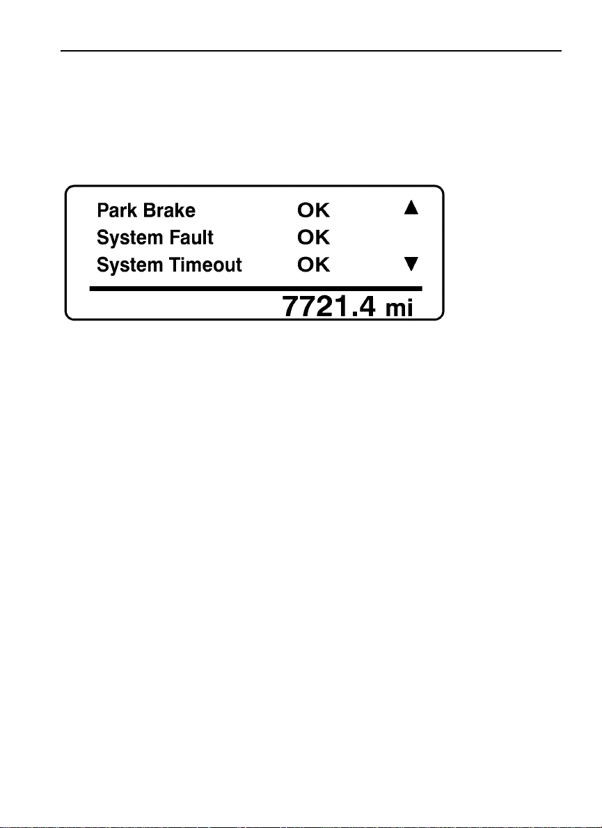
To perform a parked regeneration, the park brake must be engaged and there can be no active
fault codes. The system will time-out if the duty cycle is inadequate to support an automatic
regeneration or if there is a problem that is preventing regeneration. Attempt to perform a
parked regeneration or take the vehicle to a VolvoTruck dealer for a service regeneration.
Page 20
12 Driver Information Display
W3007447
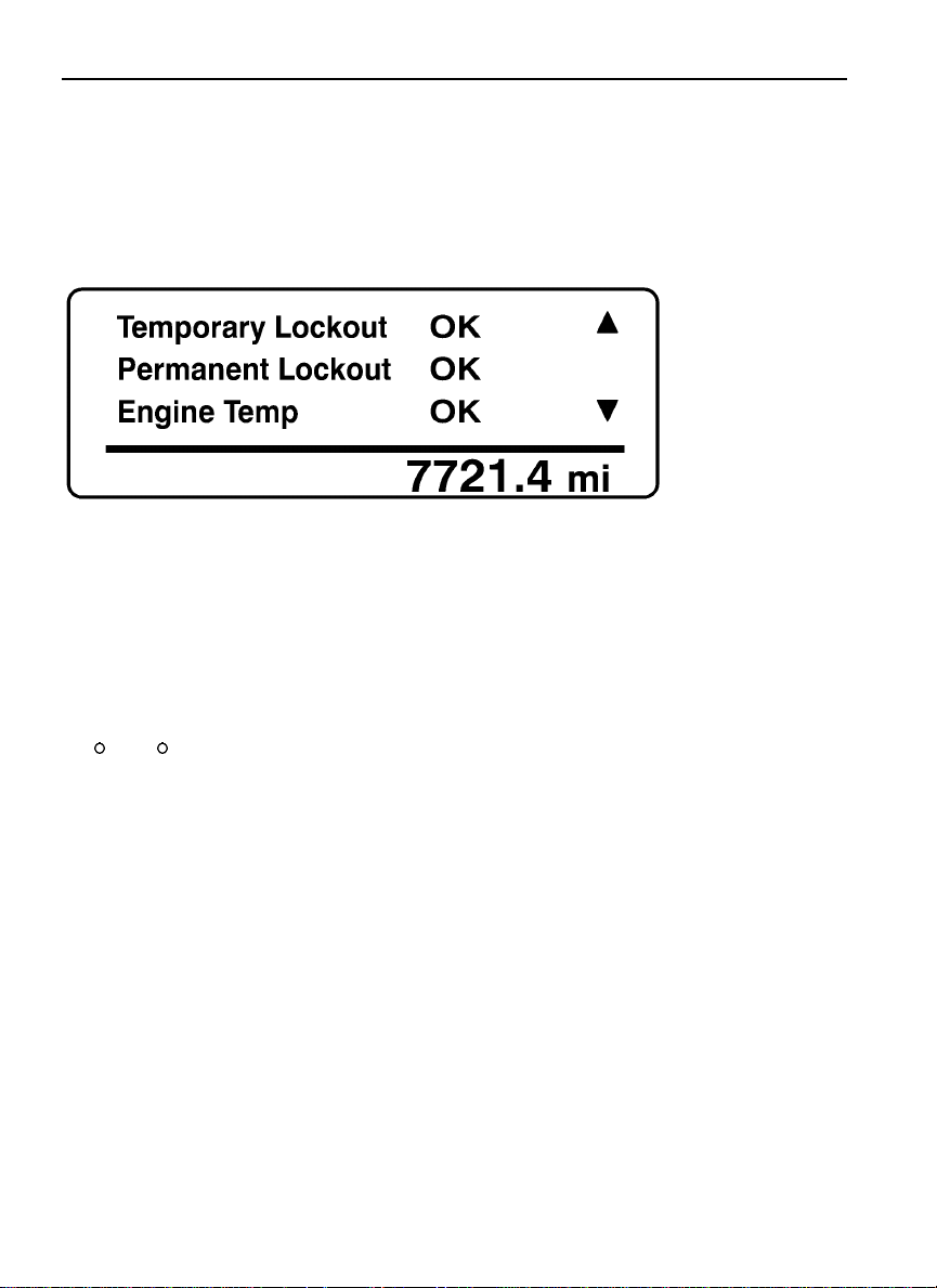
Temporary lockout prevents performing a regeneration when a regeneration is not needed.
Permanent lockout prevents performing a regeneration when a condition exists that requires
vehicle service. Take the vehicle to a Volvo Truck dealer. A minimum engine temperature of
35
C (95 F) is required for regeneration.
Page 21
Driver Information Display 13
W3007446
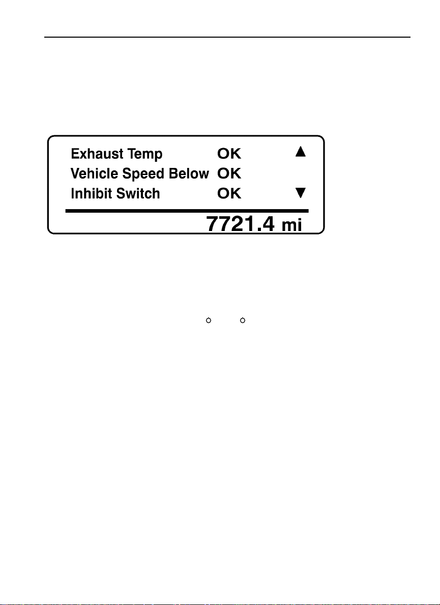
A minimum exhaust temperature of 250 C (482 F) is required for regeneration. The
minimum vehicle speed for an automatic regeneration is 40 km/h (25 mph). When Disable
REGEN is selected in the Cancel REGEN submenu, regeneration is inhibited. Select Enable
REGEN to allow regeneration.
Page 22
14 Driver Information Display
MID-LEVEL AND HIGH-LEVEL INSTRUMENT CLUSTER
DID
Note: Depending on vehicle configuration, some menus may not be available.
The Driver Information Display (DID) is located in the center of the mid-level and high-level
instrument clusters. It displays digital gauges, main menus and sub-menus that provide
necessary and important information to the vehicle operator.
The information available to the operator depends on vehicle configuration, and whether
the vehicle is in operation or parked. Certain functions are password-protected and are not
shown until the correct password is entered. See “Password” page 101.
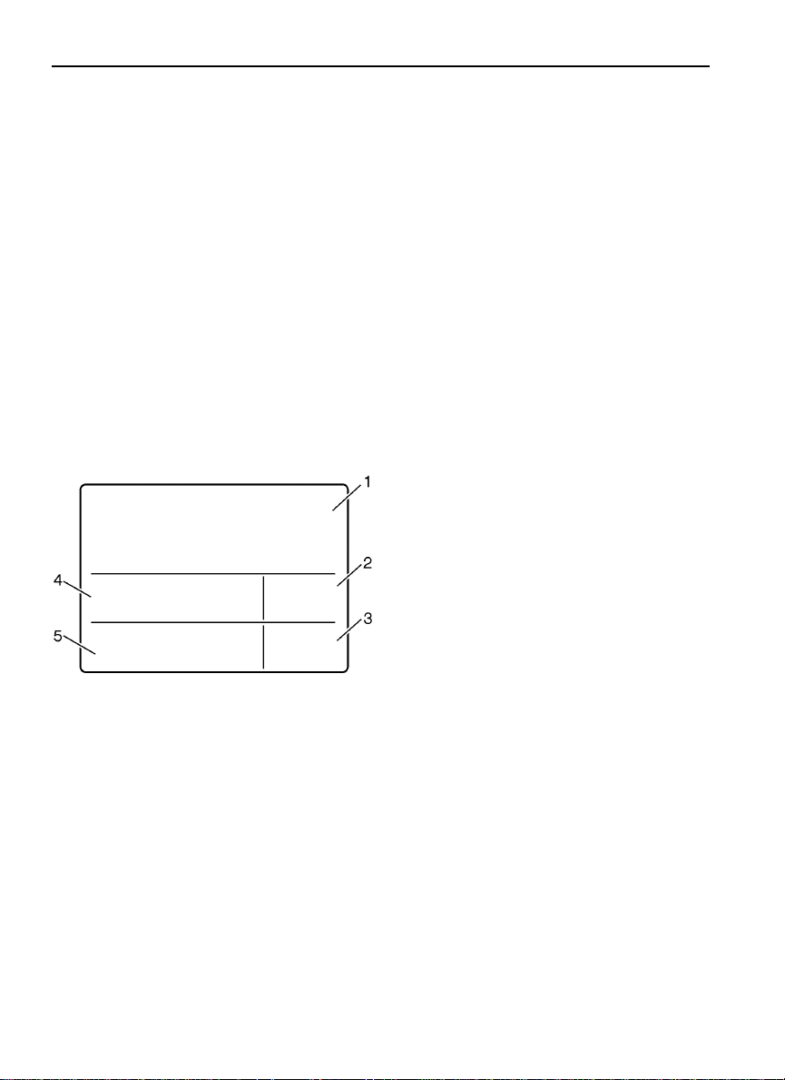
There are three sections of display information in the DID:
Top — Messages and available menus
•
Middle — Favorite display
•
Bottom — Current status and odometer
•
1 Messages and Available
Menus
2 Clock
3 Odometer
4 Favorite Display
5 Current Status
W3005515
Page 23
Driver Information Display 15
The top section displays messages, selected digital gauges, and the available DID menus.
The favorite display, clock, odometer and current status are always visible. The current
status section provides status information required at all times.
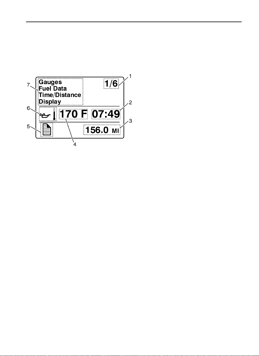
DID, example screen view:
W3005172
1 Indicates First of Six Available
Menus (varies by menu)
2 Clock
3 Odometer
4 Favorite Display
5 Current Status Icon(s)
6 Oil Temperature
7 Messages and Available
Menus
Page 24

16 Driver Information Display
Mid-Level and High-Level DID Menus
There are Driving and Non-Driving menus. Several sub-menus are password-protected while
the vehicle is parked. The Non-Driving menu is accessible only when the vehicle is parked.
Driving Menus
Gauges
•
— Current Gear Position (Automated Transmission)
— Outside Temperature
— Temperature Engine Oil
— Temperature Transmission
— Battery Voltage
— Axle Temperature (Front/Rear)
— Air Suspension (Front/Rear)
— Volvo Link Compass
Fuel Data
•
Instantaneous Gallons per Hour
— Trip Fuel Used
— Distance to Empty
— Fuel Economy
— Idle Percent
— Sweet Spot/Performance Bonus
— Sweet Spot Percentage
— Road Speed Limit
Time/Distance
•
Aftertreatment
•
— Time and Date
— Alarm Clock
— Distance to Destination
— Average Trip Speed
— Estimated Time of Arrival (ETA)
— Request Parked REGEN
— ATS Status
— Delay REGEN
— Cancel REGEN
Page 25

Driver Information Display 17
Volvo Link
•
— Read Message
— Send Message
— Other Info
Display
•
— Black Panel
— Favorite Display
— Backlight
— Favorite Display Setting
— Night/Day
Vehicle Messages
•
Aftertreatment
•
Digital Gauges in the DID (High and Mid Level Cluster Only)
There are several gauges in the Gauges menu. The number of gauges your vehicle is
programmed with depends on the equipment level of the vehicle. The gauges are used to
view current status of important functions in the vehicle.
All gauges are programmed into the instrument cluster and are therefore visible only in
the DID.
Current Gear Position (Automated Transmission)
•
Outside Temperature
•
Engine Oil Temperature
•
Transmission Temperature
•
Battery Voltage
•
Front and Rear Axle Temperature
•
Front and Rear Suspension Pressure
•
Volvo Link Compass
•
Page 26
18 Driver Information Display
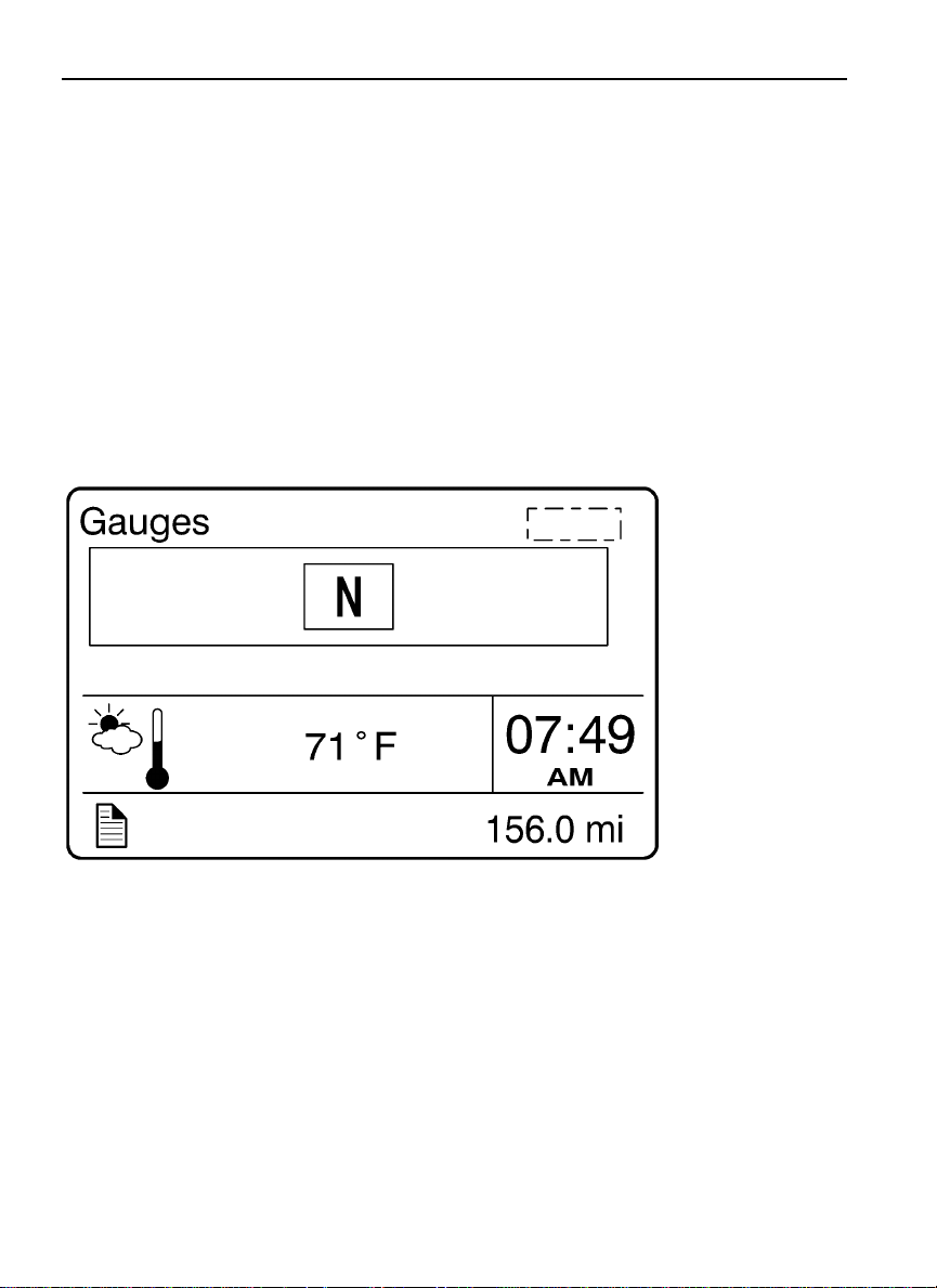
1. Current Gear Position (Automated Transmission)
Note: When the vehicle is equipped with an automated transmission, the current
transmission gear position is always displayed in the favorites display section.
The current gear position gauge is standard with automated transmissions.
N = Neutral
•
R = Reverse
•
Forward Gear = 1 – 18 (varies with type of transmission)
•
W3007430
Page 27
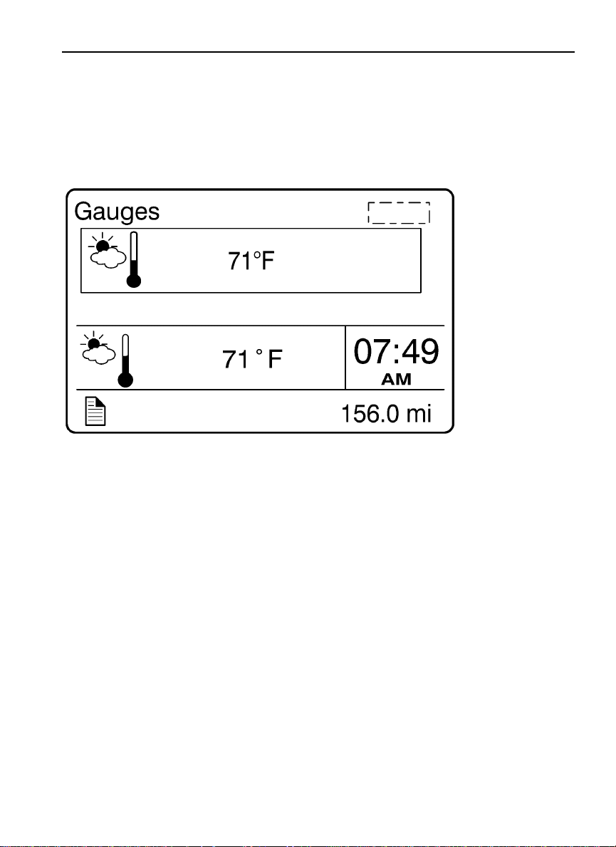
2. Outside Temperature
The outside temperature gauge is optional.
Driver Information Display 19
W3007429
Page 28
20 Driver Information Display
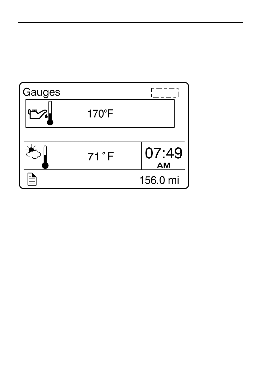
3. Engine Oil Temperature
The engine oil temperature is displayed as illustrated
W3007428
Page 29
Driver Information Display 21
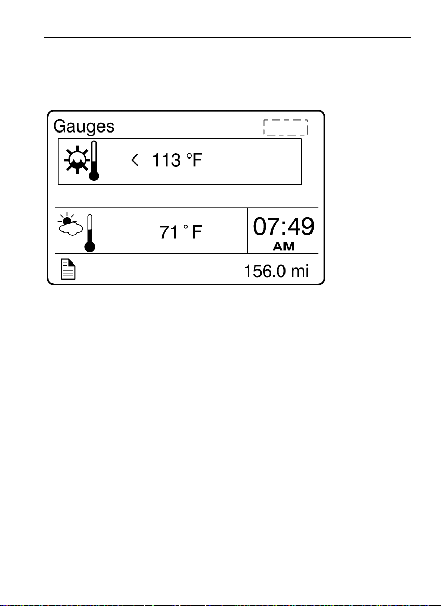
4. Transmission Oil Temperature
W3007427
Page 30
22 Driver Information Display
5. Battery Voltage
W3007426
Page 31
Driver Information Display 23
6. Front and Rear Axle Temperature
W3007425
Page 32
24 Driver Information Display
7. Front and Rear Suspension Pressure
W3007424
Page 33
8. Volvo Link Compass
Fuel Data
Driver Information Display 25
W3007423
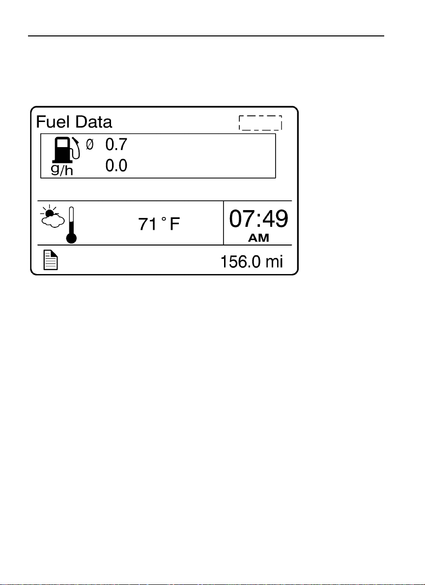
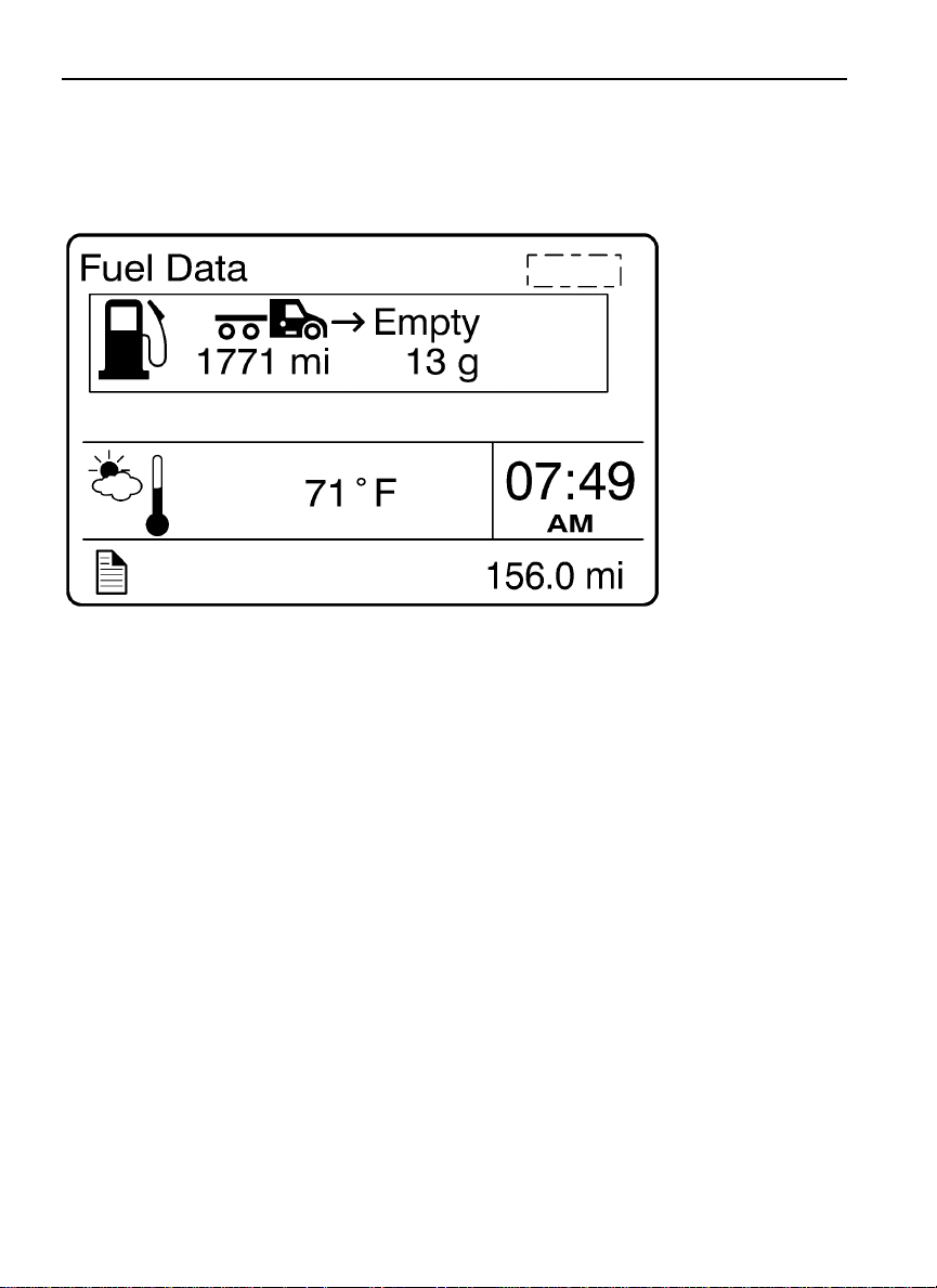
The Fuel Data menu provides information on the fuel consumption of the vehicle in various
situations. For example, how much fuel has been used, how much fuel is remaining, how
much fuel is remaining before refueling the vehicle.
Instantaneous Gallons Per Hour
•
Trip Fuel Used
•
Distance to Empty
•
Fuel Economy
•
Idle Percent
•
Sweet Spot/Performance Bonus
•
Sweet Spot Percentage
•
Road Speed Limit
•
Page 34
26 Driver Information Display
1. Instantaneous Gallons Per hour
W3007422
Page 35
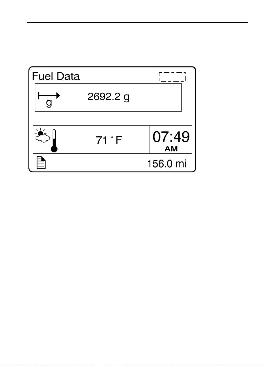
2. Trip Fuel Used
Driver Information Display 27
W3007421
Page 36
28 Driver Information Display
3. Distance to Empty
W3007420
Page 37
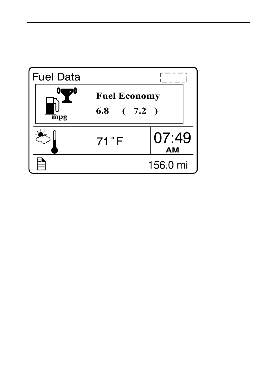
4. Fuel Economy
Driver Information Display 29
W3007419
Page 38
30 Driver Information Display
5. Idle Percent
W3007418
Page 39
Driver Information Display 31
6. Sweet Spot/Performance Bonus
Note: For information about sweet spot data, refer to Performance Bonus Guide in the
vehicle operator’s manual.
W3007417
Page 40
32 Driver Information Display
7. Sweet Spot Percentage
Note: For information about sweet spot data, refer to Performance Bonus Guide in the
vehicle operator’s manual.
W3007416
Page 41
8. Road Speed Limit
Driver Information Display 33
W3007415
Page 42
34 Driver Information Display
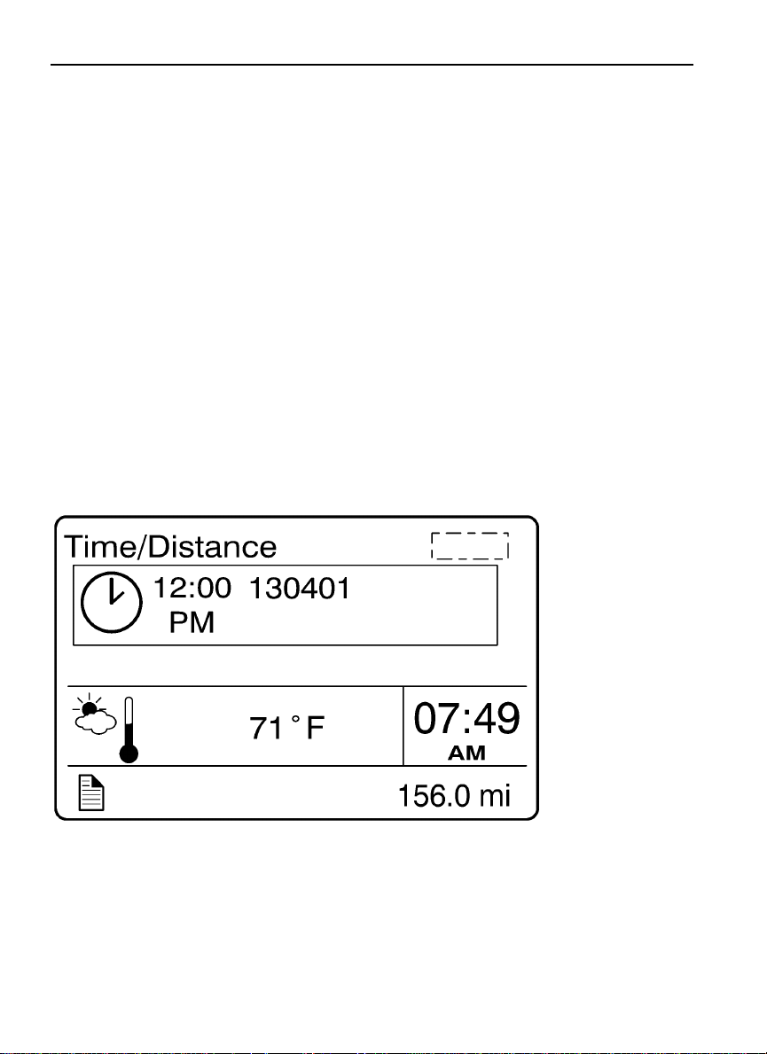
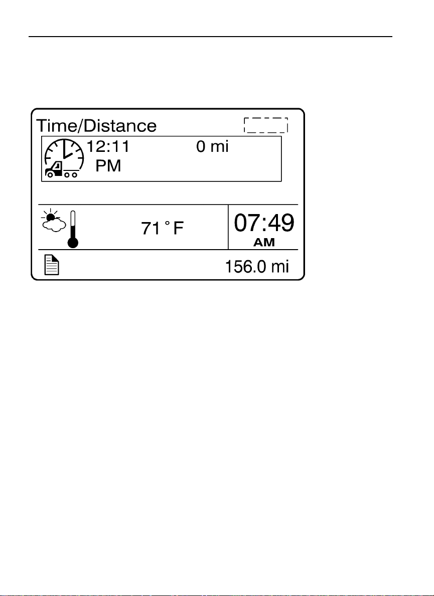
Time/Distance
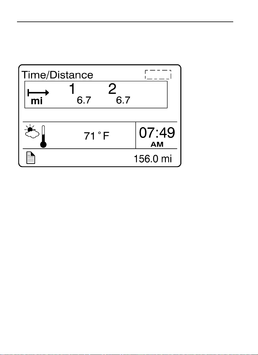
The time and date can be set in the Time/Distance menu. The alarm clock can also be set
from this menu. Following the alarm clock menu is the Distance to Destination selection,
which allows the operator see the distance since the last reset. Average trip speed is
also shown. By specifying the distance to your destination, the vehicle can calculate the
estimated time of arrival (ETA).
Time and Date
•
Alarm Clock
•
Distance to Destination
•
Average Trip Speed
•
Estimated Time of Arrival (ETA)
•
1. Time and Date
W3007414
Page 43
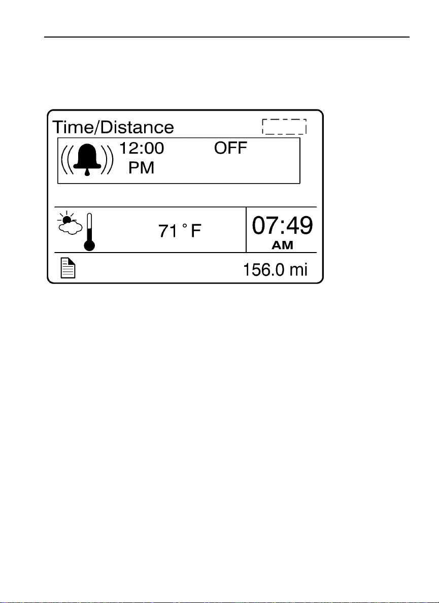
2. Alarm Clock
Driver Information Display 35
W3007413
Page 44
36 Driver Information Display
3. Distance to Destination
W3007412
Page 45
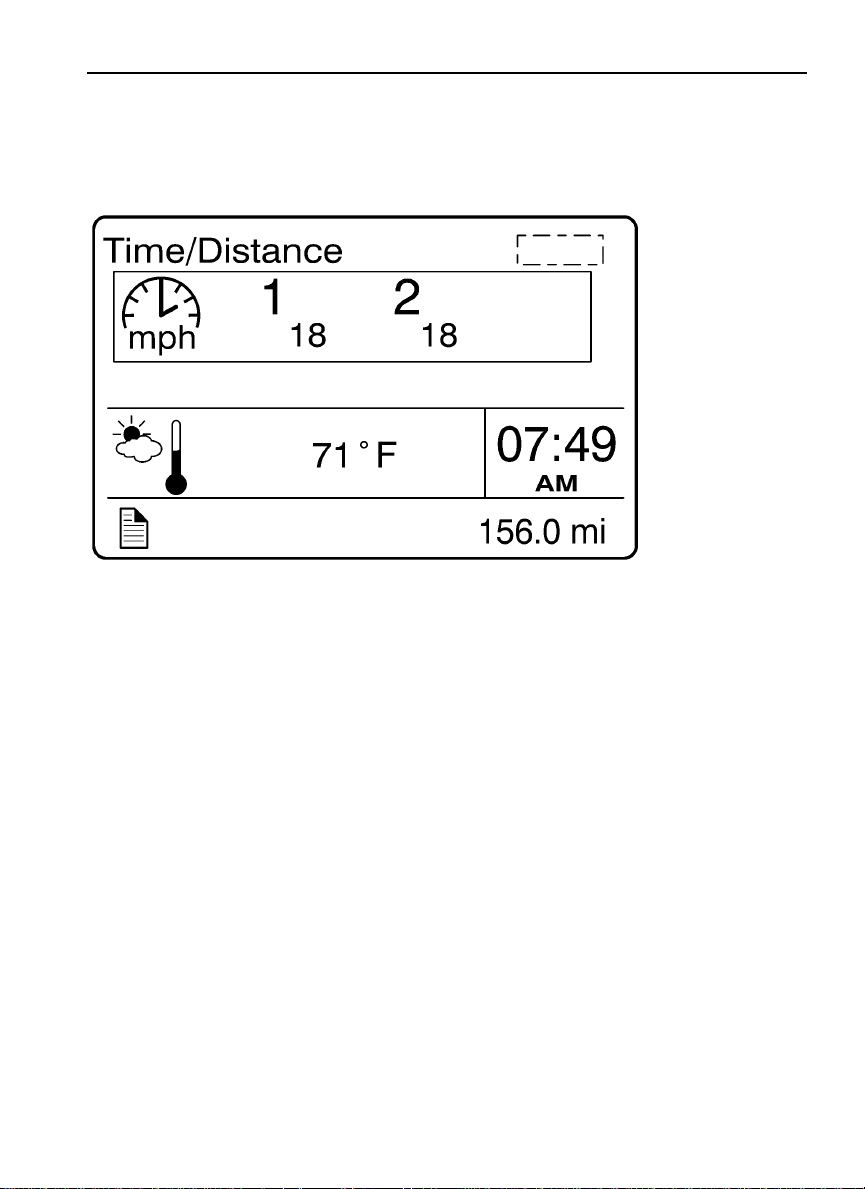
4. Trip Average Speed
Driver Information Display 37
W3007411
Page 46
38 Driver Information Display
5. Estimated Time of Arrival (ETA)
W3007410
Page 47
Driver Information Display 39
Aftertreatment
Note: For additional information about the aftertreatment system, refer to the vehicle
operator’s manual.
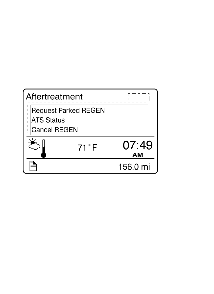
The Aftertreatment menu allows the operator to request a parked regeneration, check the
status of the aftertreatment system, and cancel a regeneration.
W3007436
Page 48
40 Driver Information Display
Aftertreatment Status
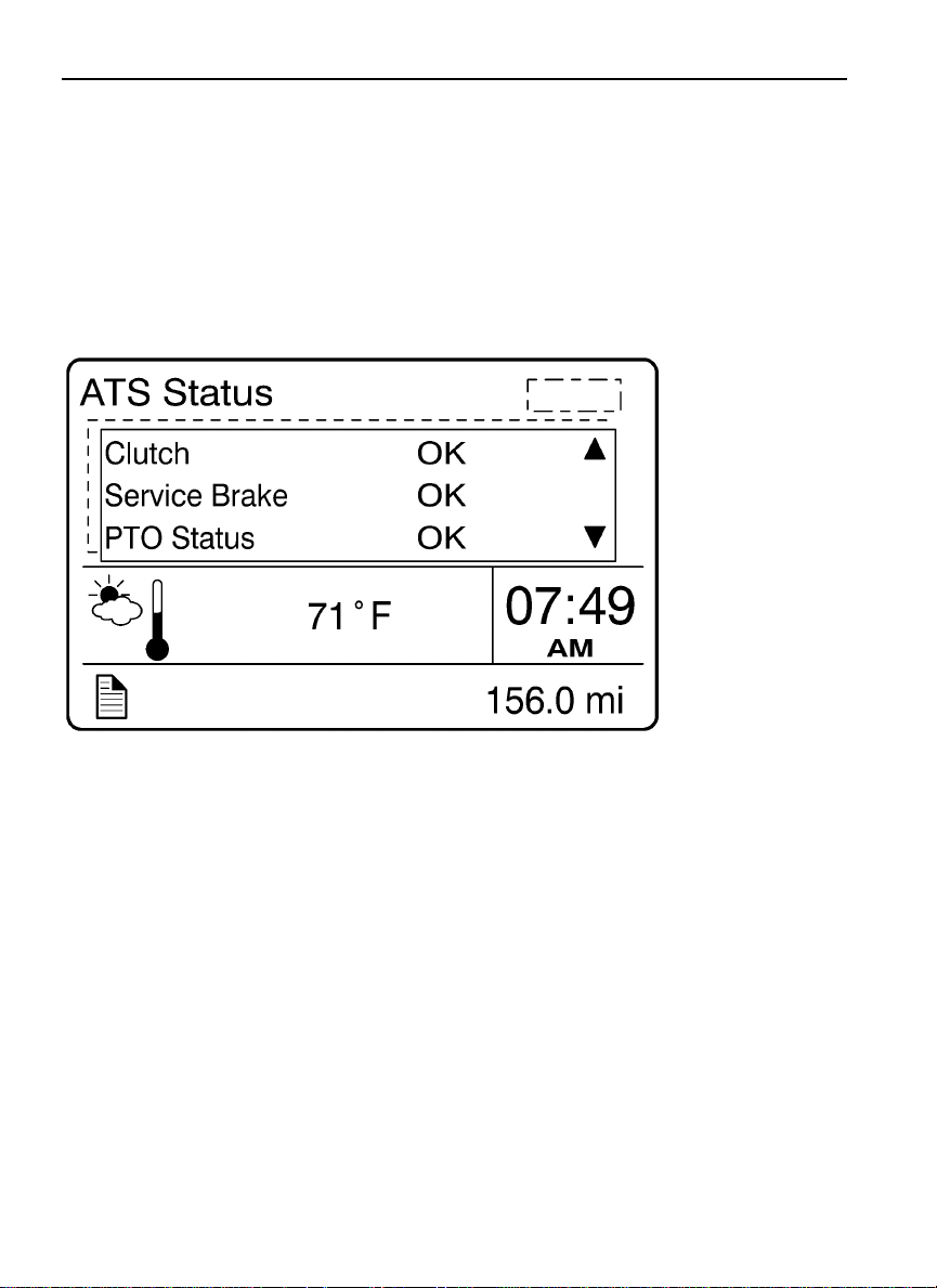
The Aftertreatment status submenus provide information about the conditions required
for performing a regeneration. The status can be OK (regeneration allowed), CHECK
(regeneration not allowed) or N/A (not applicable). When ATS Status is selected, the
following submenus are available.
W3007435
To perform a parked regeneration, the clutch pedal must not be depressed, the service brake
must not be engaged and a PTO must not be engaged or the PTO must be able to operate
above the minimum engine speed required.
Page 49
Driver Information Display 41
W3007434
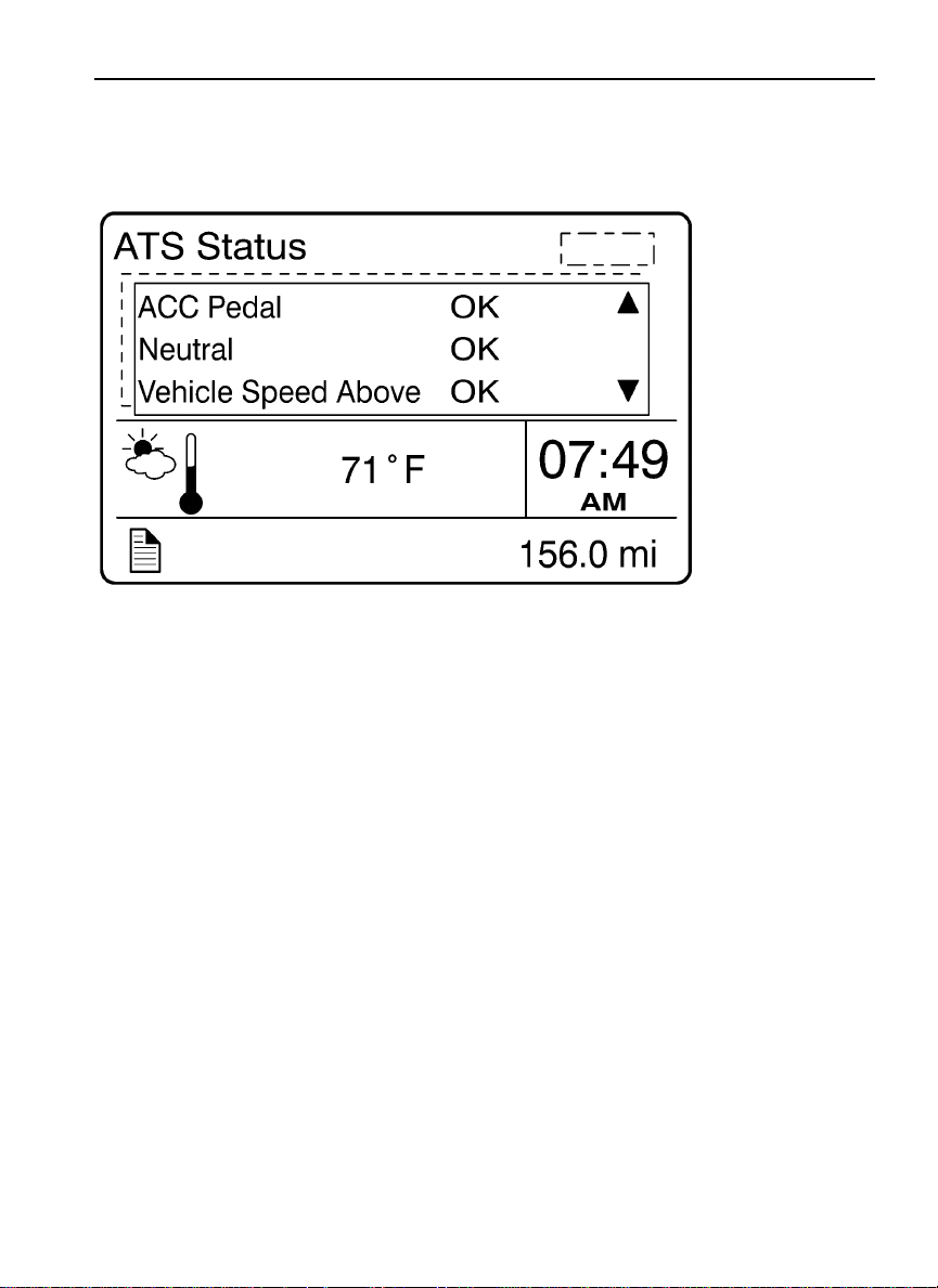
To perform a parked regeneration, the accelerator pedal must not be depressed, the
transmission must be in the neutral position and the vehicle speed must not be above zero.
Page 50
42 Driver Information Display
W3007433
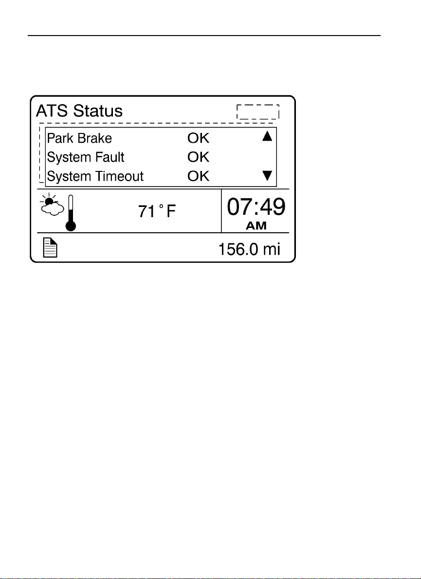
To perform a parked regeneration, the park brake must be engaged and there can be no active
fault codes. The system will time-out if the duty cycle is inadequate to support an automatic
regeneration or if there is a problem that is preventing regeneration. Attempt to perform a
parked regeneration or take the vehicle to a Volvo Truck dealer for a service regeneration.
Page 51
Driver Information Display 43
W3007432
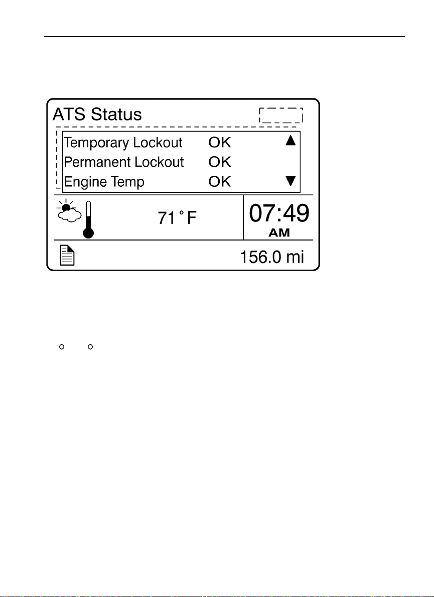
Temporary lockout prevents performing a regeneration when a regeneration is not needed.
Permanent lockout prevents performing a regeneration when a condition exists that requires
vehicle service. Take the vehicle to a Volvo Truck dealer. A minimum engine temperature of
35
C (95 F) is required for regeneration.
Page 52
44 Driver Information Display
W3007431
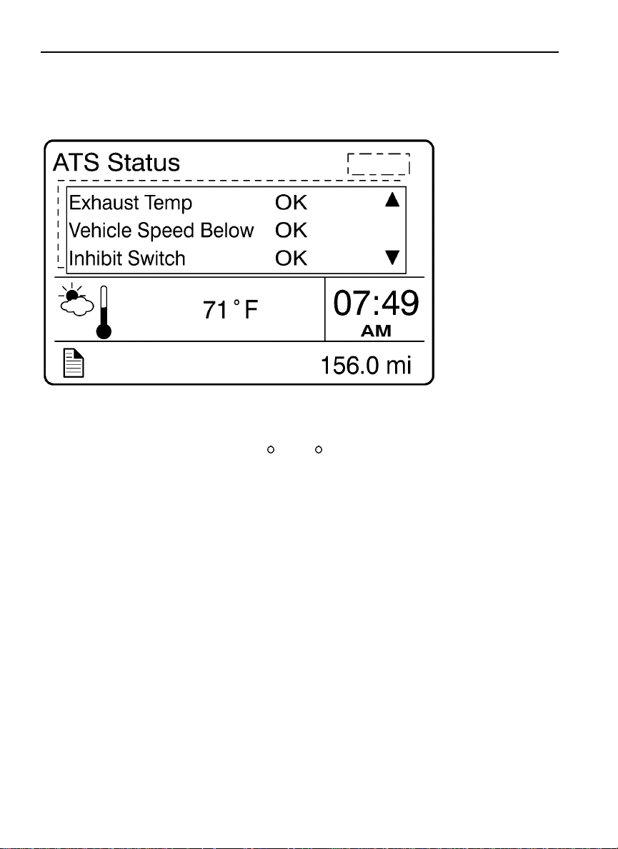
A minimum exhaust temperature of 250 C (482 F) is required for regeneration. The
minimum vehicle speed for an automatic regeneration is 40 km/h (25 mph). When Disable
REGEN is selected in the Cancel REGEN submenu, regeneration is inhibited. Select Enable
REGEN to allow regeneration.
Page 53
Driver Information Display 45
W3030053
W3030054
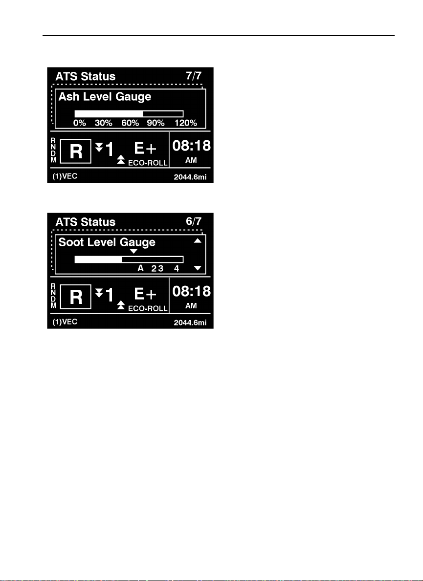
From the ATS Status submenu, you can view both the Ash and Soot levels for the
Aftertreatment system.
Page 54
46 Driver Information Display
W3030055
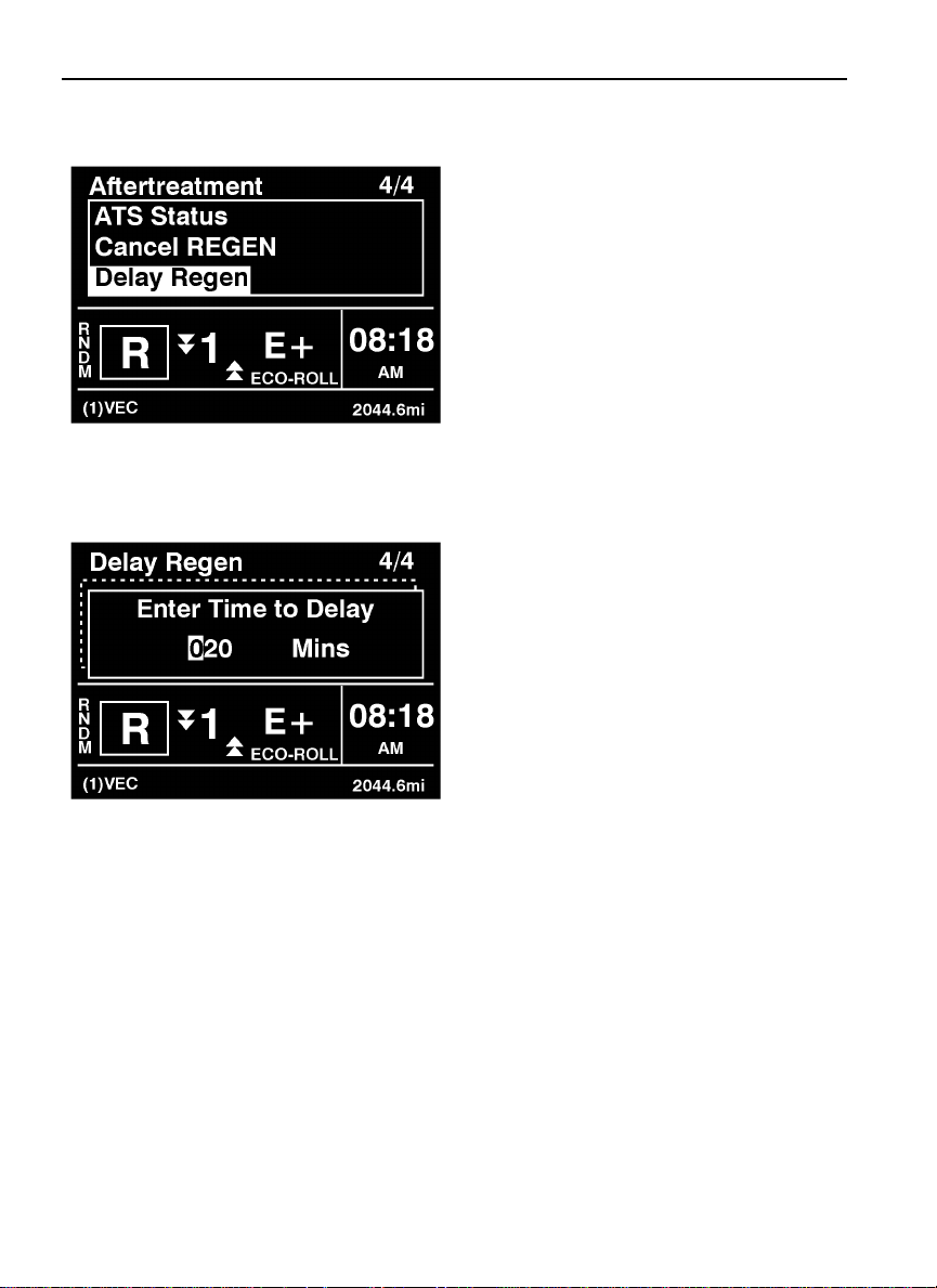
From the Aftertreatment main menu, you can either cancel or delay a REGEN cycle.
W3030056
From the Delay REGEN submenu, you can set the amount of time to delay the REGEN cycle.
Page 55
Driver Information Display 47
W3030057
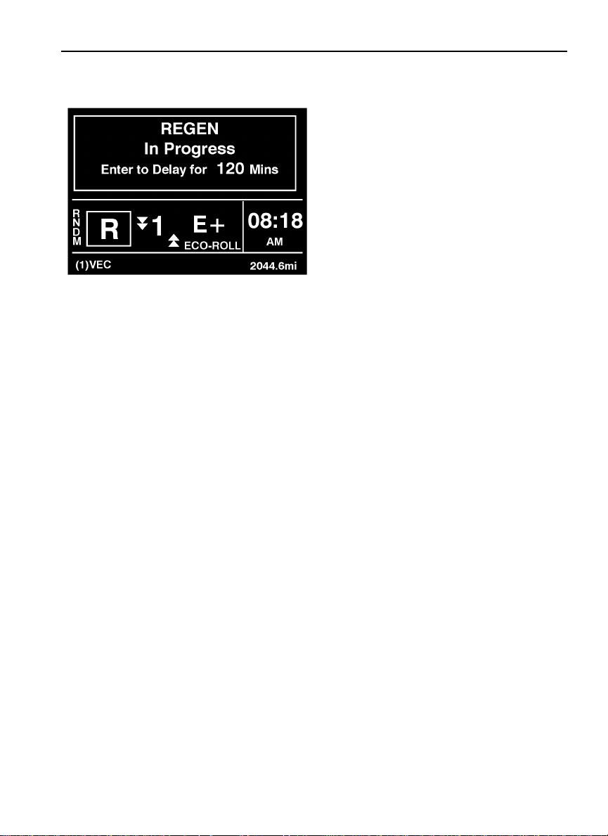
After the delay is set, and the REGEN process starts, the REGEN In Progress screen
displays.
Page 56
48 Driver Information Display
Volvo Link
W3007688
Main Menu
W3007689
Start-Up Menu
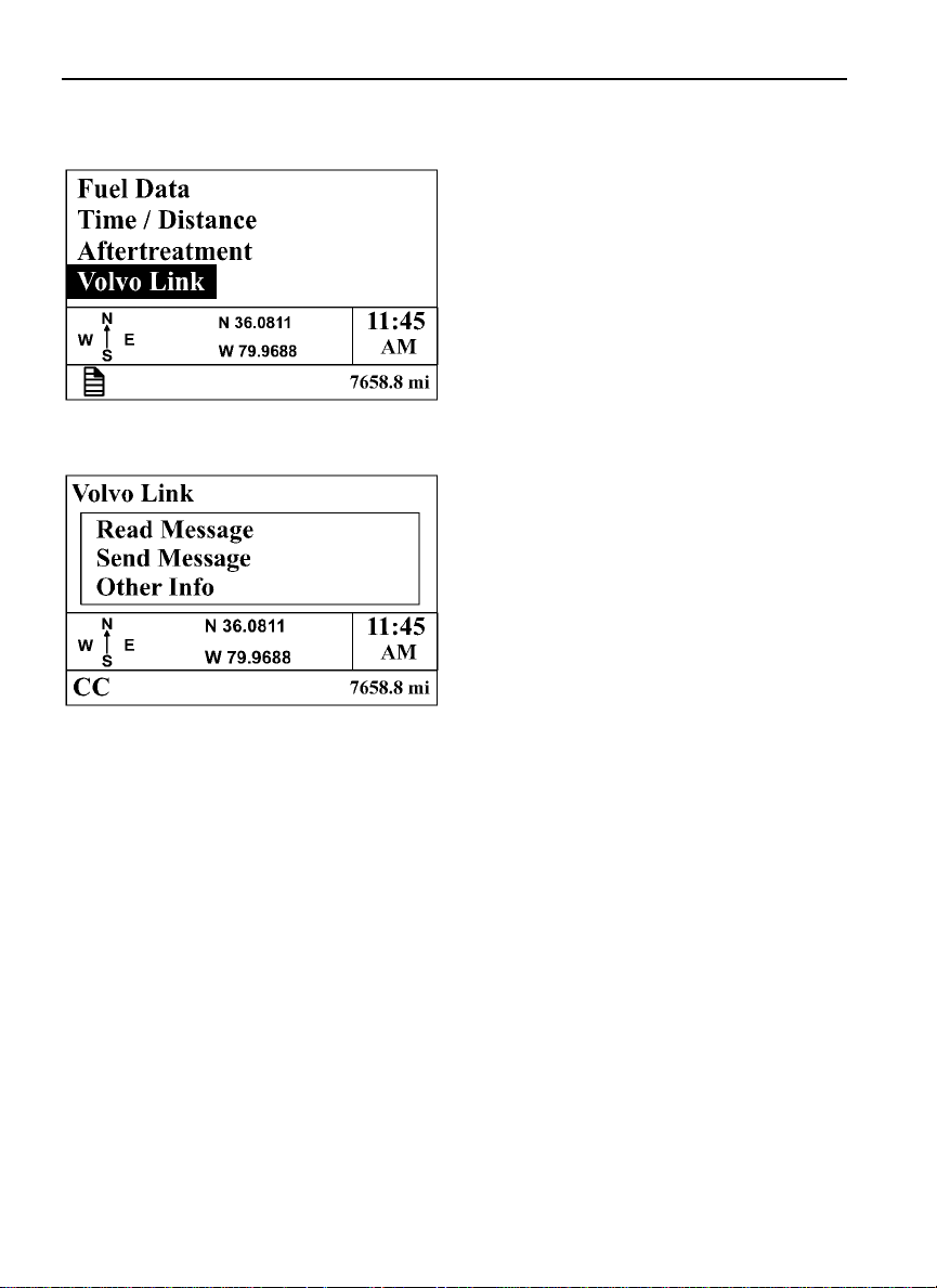
For information about the Volvo Link System, refer to the Volvo Link System Operator’s
Manual.
Page 57
Driver Information Display 49
Display
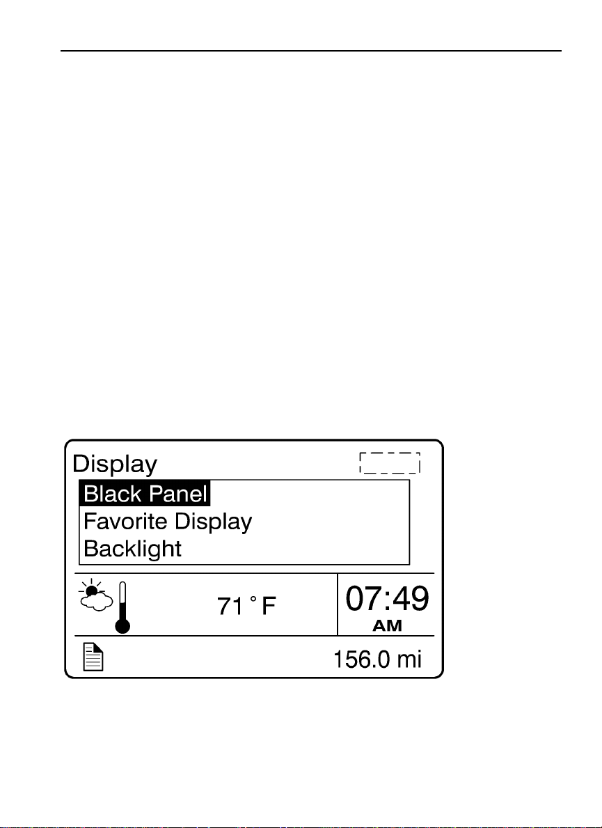
The operator can adjust the display in the Display menu. The entire display can be blacked
out for night driving. The display brightness level is adjustable. The Favorite Display
function allows the operator to select up to three different gauges to be displayed at the same
time. Night/Day can be selected to provide a light or dark background.
Black Panel
•
Favorite Display
•
Backlight
•
Favorite Display Setting
•
Night/Day
•
1. Black Panel
The screen and the entire display is completely dark, except the speedometer and tachometer.
The black panel mode can be exited by pressing the Esc button.
W3007409
Page 58
50 Driver Information Display
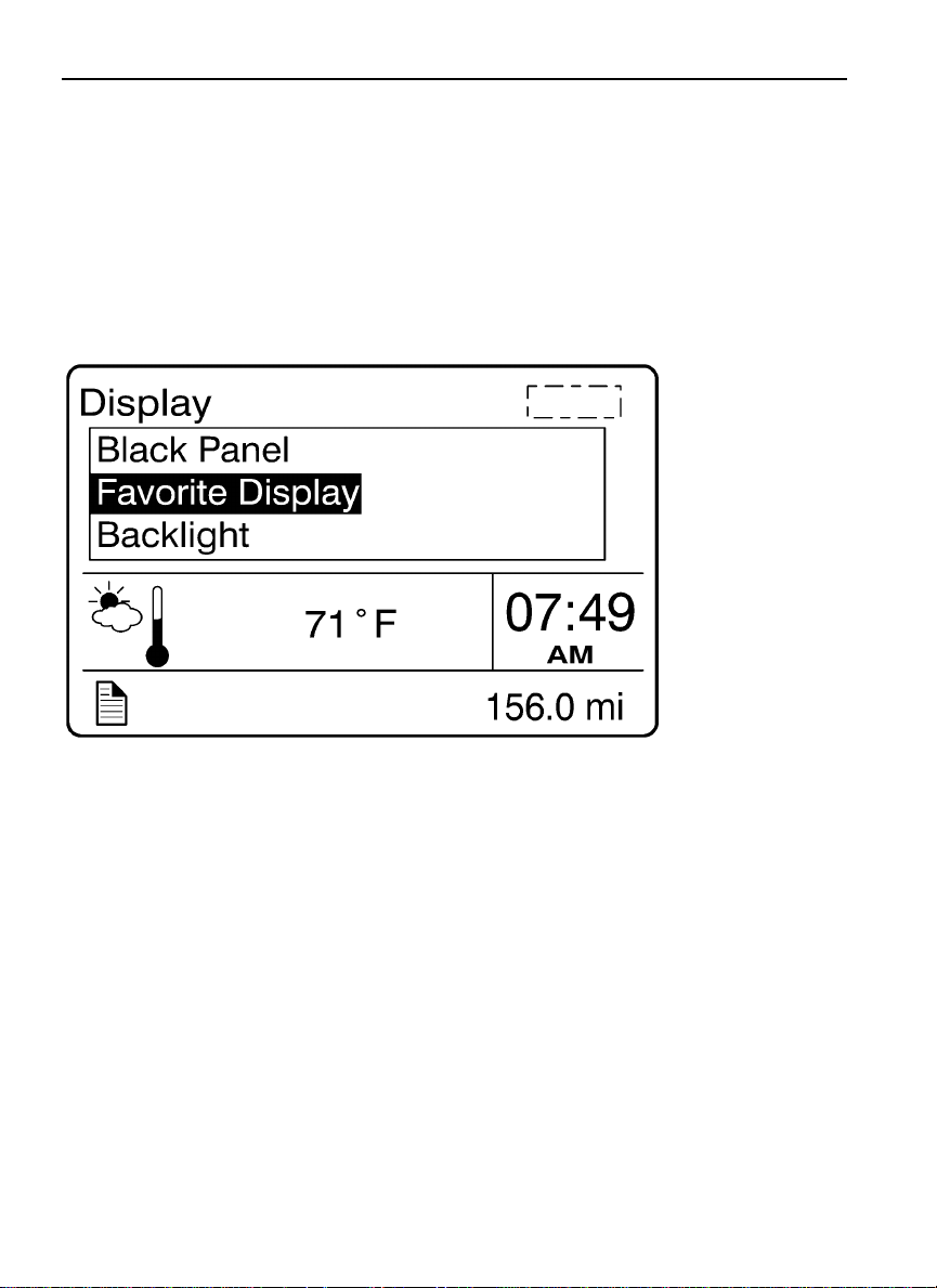
2. Favorite Display
Note: This section is for viewing your selection only. To choose your favorite selection, go
to Favorite Display Setting (see “4. Favorite Display Setting” page 52).
If Favorite Display is selected, the DID will always display the selected gauges.
W3007408
Page 59
Driver Information Display 51
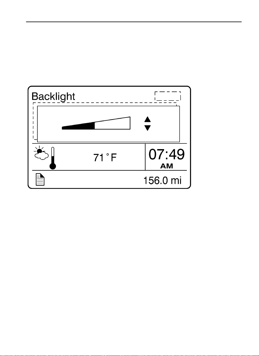
3. Backlight
To increase or decrease the backlight setting, press the up and down arrows on the stalk
switch.
W3007407
Page 60
52 Driver Information Display
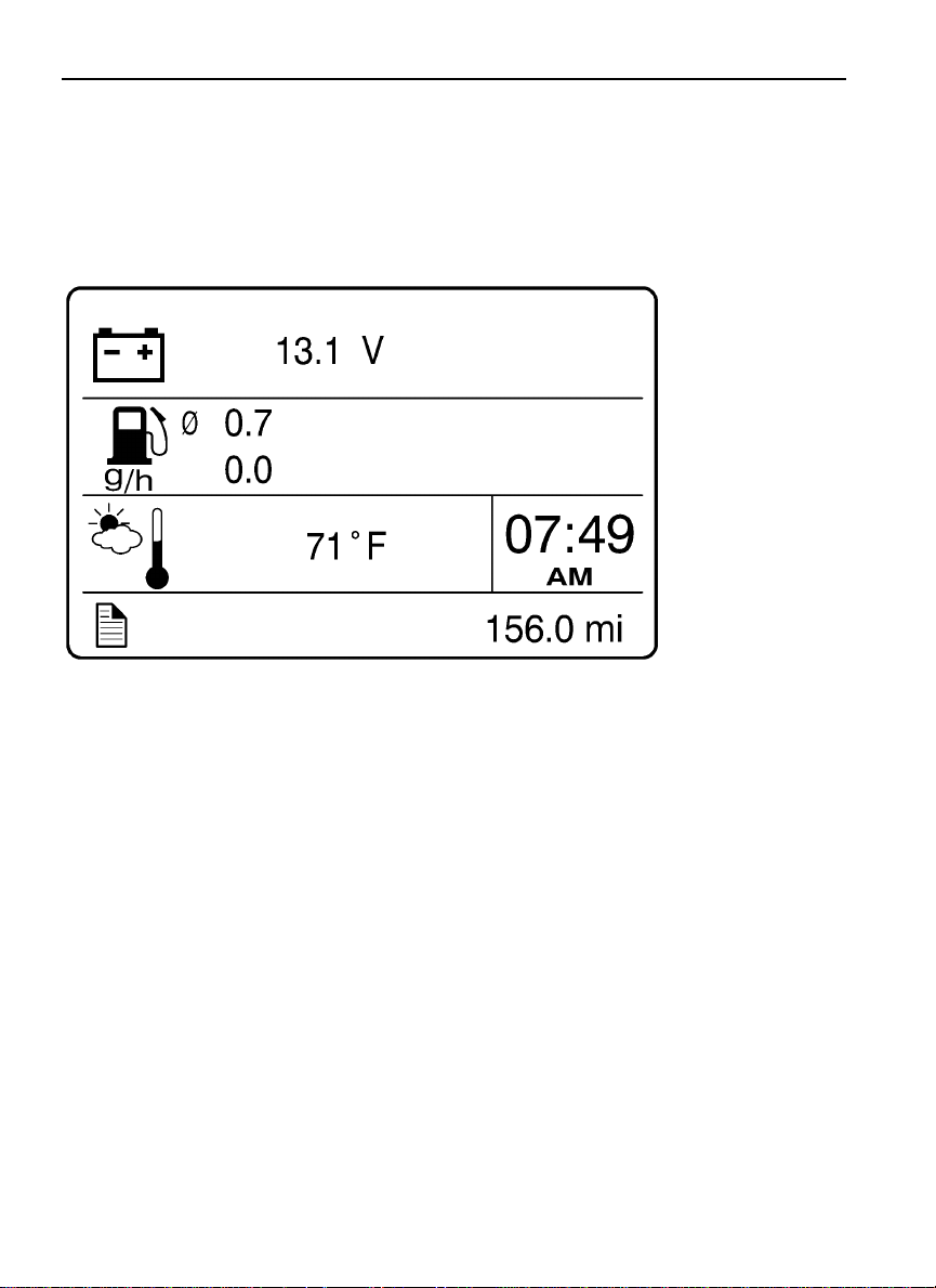
4. Favorite Display Setting
Select Favorite Display Setting to choose the gauges displayed on the DID.
W3007406
5. Night/Day
Use the Night/Day menu to choose a dark background with light text and images or a light
background with dark text and images.
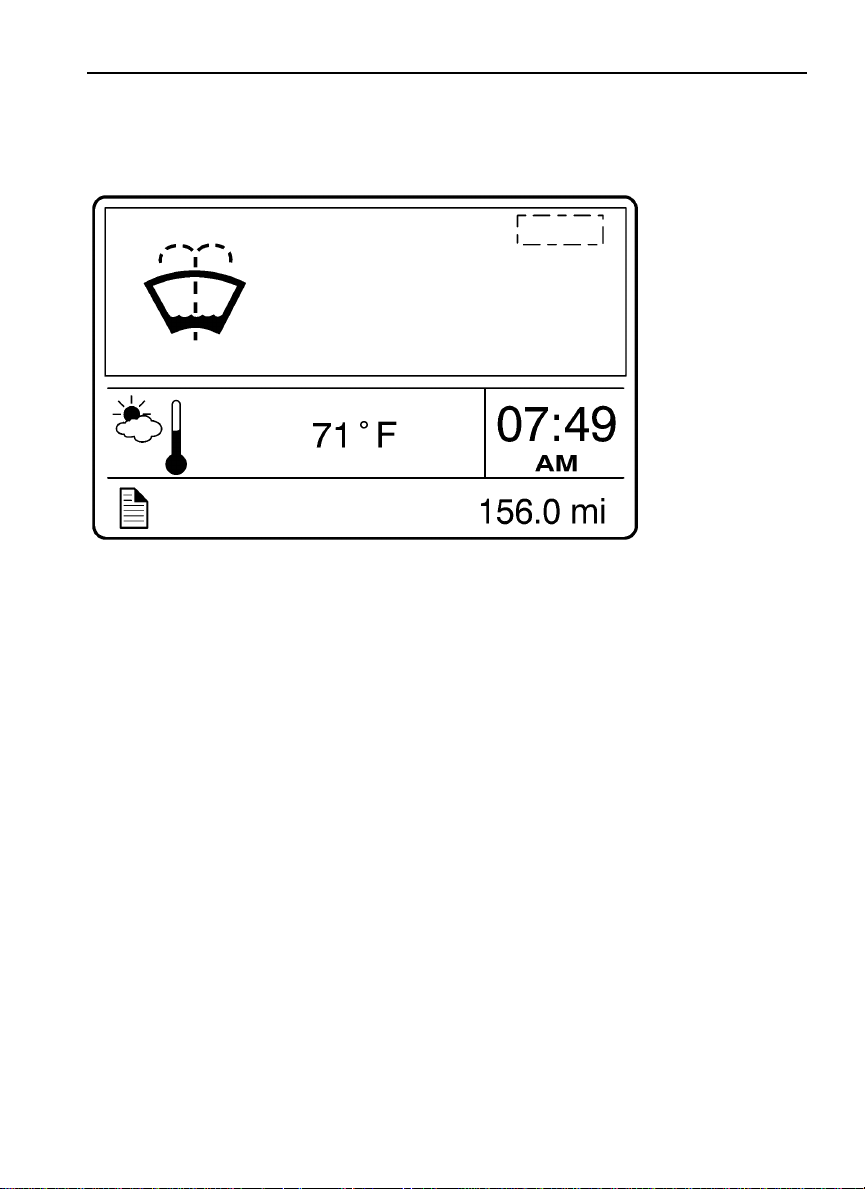
Vehicle Messages
Vehicle Messages appear in the DID depending on the number of faults the vehicle has at
any given time.
Page 61
Windshield Washer Fluid Low
Message
Driver Information Display 53
W3007405
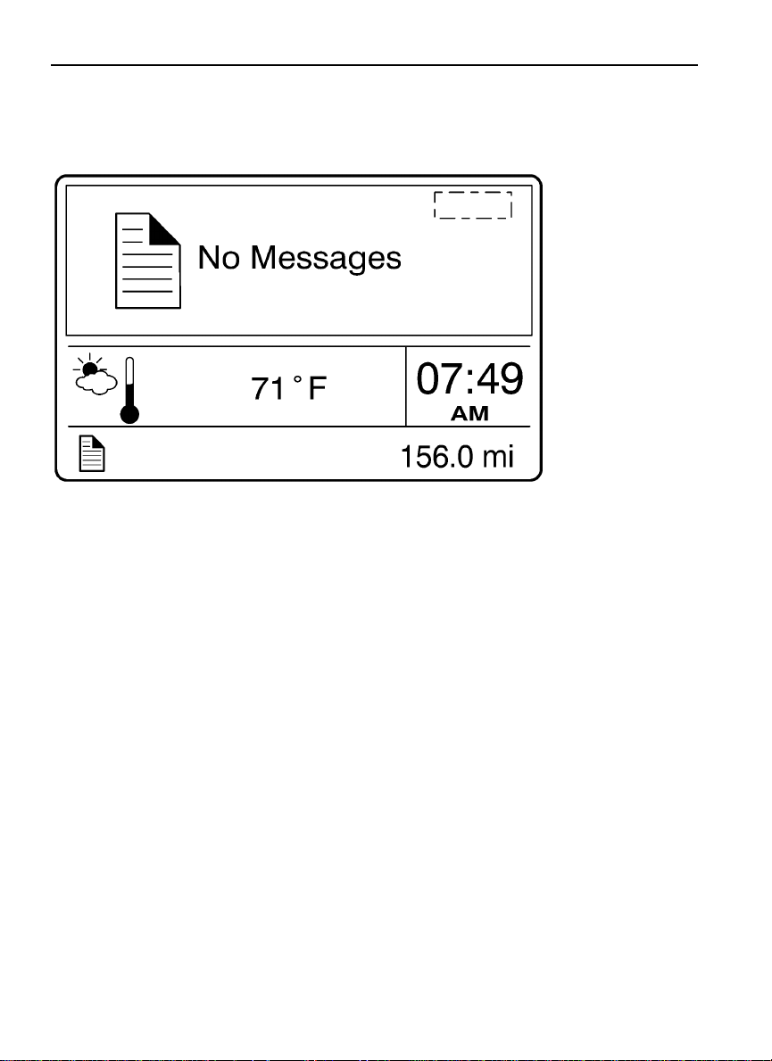
If there are no messages, the following screen is displayed.
Page 62
54 Driver Information Display
W3007404
Page 63
Driver Information Display 55
Reset
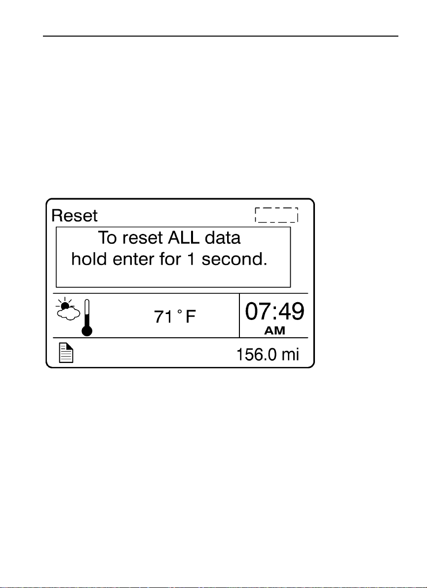
When the Reset menu is open, pressing and holding down the Enter button for more than 1
second resets the following functions:
Instantaneous gallons per hour
•
Trip fuel used
•
Distance to empty
•
W3007403
Page 64
56 Driver Information Display
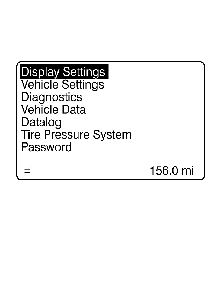
Non-Driving/Stationary Menu
W3029786
Page 65

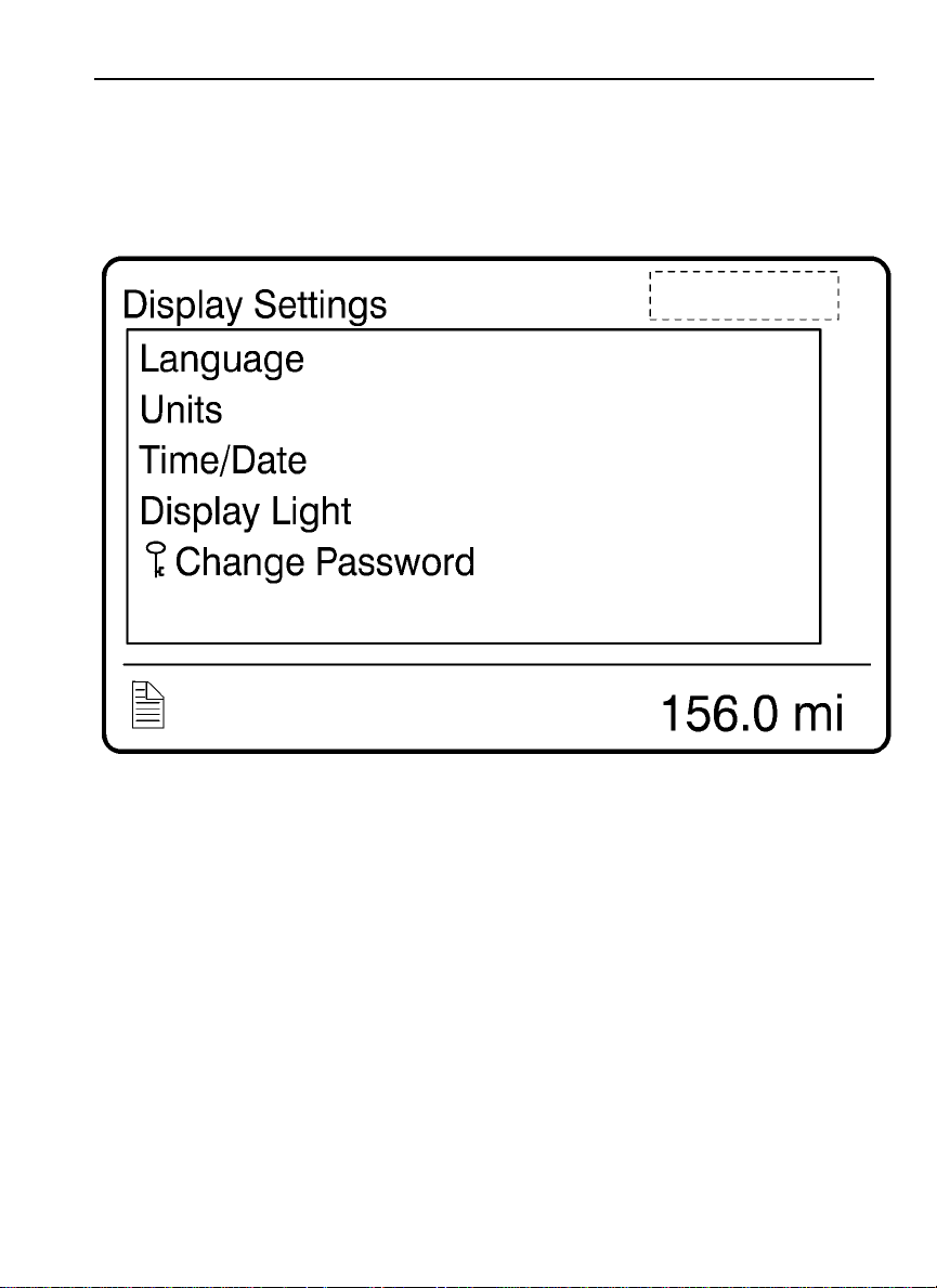
Display Setting
•
— Language
— Units
— Time/Date
— Display Light
— Change Password
Vehicle Settings (Volvo engines only)
•
— Fleet Limits
— Fleet ID
— Water in Fuel (if equipped)
Diagnostics
•
— Fault Diagnostics
— Cluster Self Test
Driver Information Display 57
— Part Number
Page 66

58 Driver Information Display
Vehicle Data (Volvo Engines Only)
•
— Oil Level
— Maintenance Data
Data Log
•
— Vehicle ID
— Sweet Spot Data
— Total Data
— Trip Data
— Reset Trip Data
Tire Pressure System
•
— Tire Pressure
— Tire Temperature
Password
•
— Enter Password
Page 67
Display Setting
Driver Information Display 59
W3029787
Page 68
60 Driver Information Display
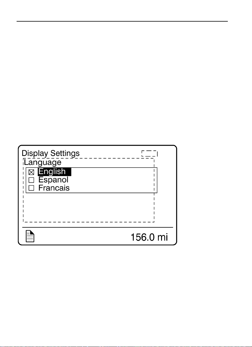
The Display Setting menu is used to change languages and units. The password, time and
date can also be changed. The backlight and contrast of the display screen can be adjusted.
Language
•
Units
•
Time/Date
•
Display/Adjust
•
Change Password
•
1. Language
W3007396
Page 69
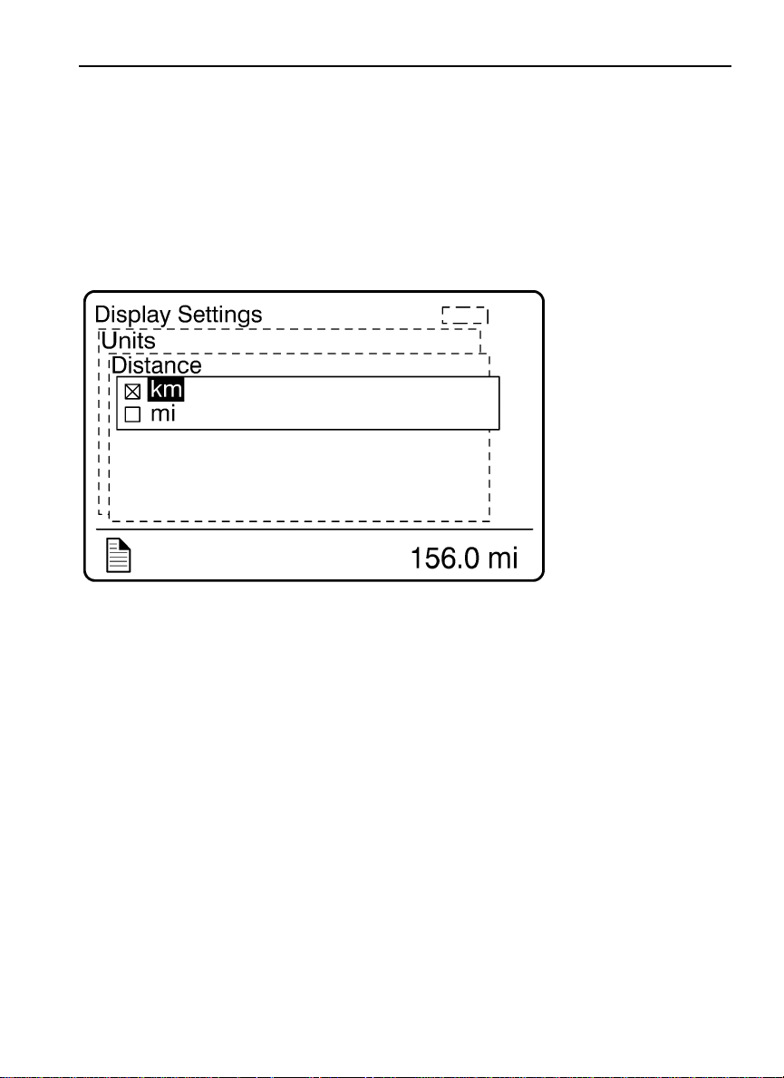
2. Units
Distance
•
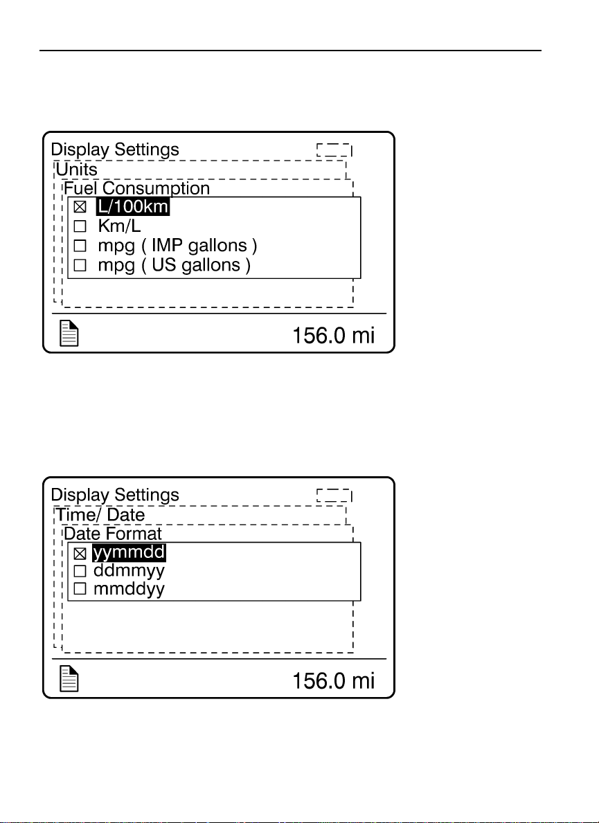
Fuel Consumption
•
Temperature
•
Driver Information Display 61
Distance
W3007395
Page 70
62 Driver Information Display
W3007394
Fuel Consumption
Date Format
W3007391
Page 71
Driver Information Display 63
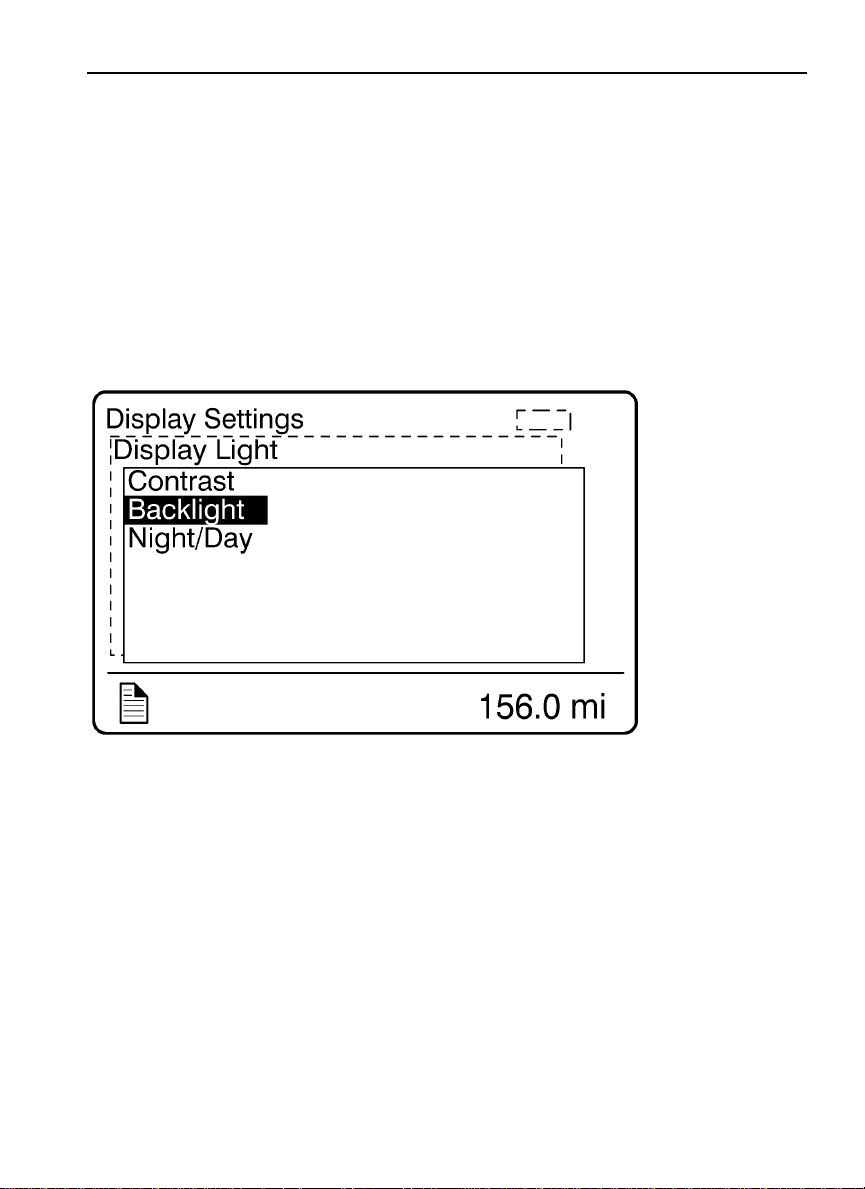
4. Display Light
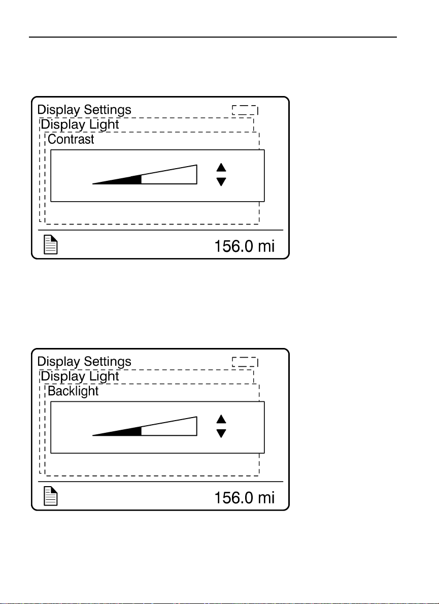
The Display Light menu has three sub-menus:
Contrast
•
Backlight
•
Night/Day
•
Use the Night/Day menu to choose a dark background with light text and images or a light
background with dark text and images.
W3007390
Page 72
64 Driver Information Display
W3007389
Contrast
Backlight
W3007388
Page 73
Driver Information Display 65
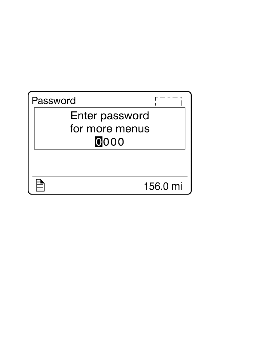
5. Change Password
Note: This menu is only accessible if the correct password is entered. The default password
from Volvo is 0000.
W3007356
Page 74

66 Driver Information Display
Vehicle Settings
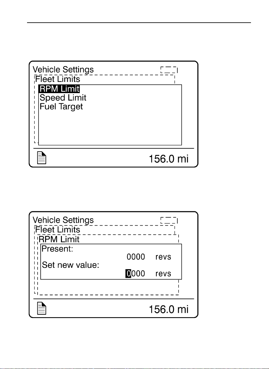
The Vehicle Settings menu allows fleet owners to set targets for vehicle operation regarding
maximum engine speed, maximum road speed, and fuel consumption.
Note: This area is password protected.
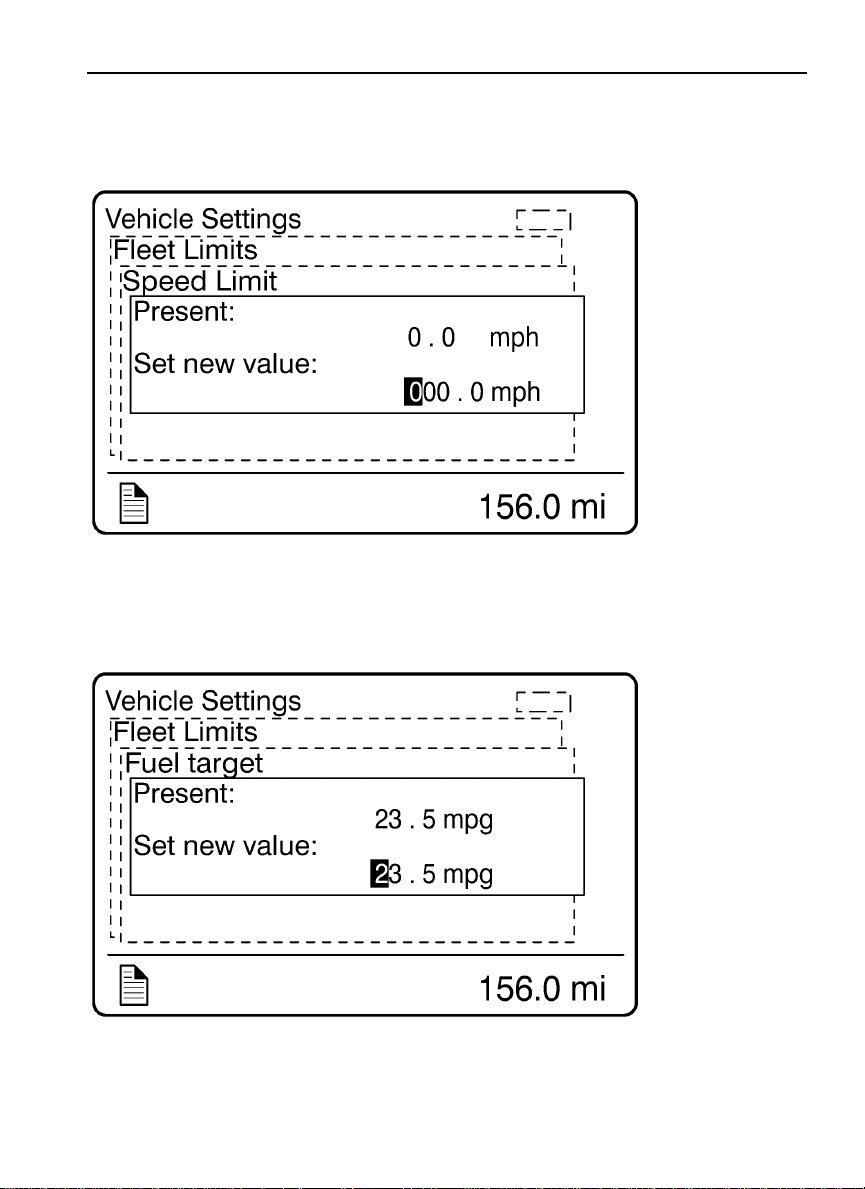
1. Fleet Limits
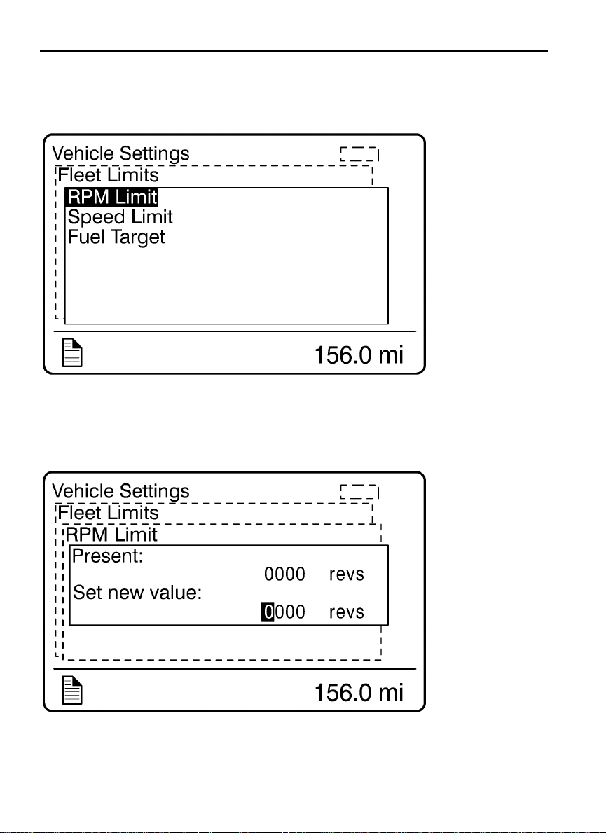
The Fleet Limits menu has three sub-menus:
RPM Limit
•
Speed Limit
•
Fuel Target
•
Page 75
Driver Information Display 67
W3007386
W3007385
Page 76
68 Driver Information Display
W3007386
RPM Limit
W3007385
Page 77
Driver Information Display 69
W3007384
RPM Limit
W3007383
Page 78
70 Driver Information Display
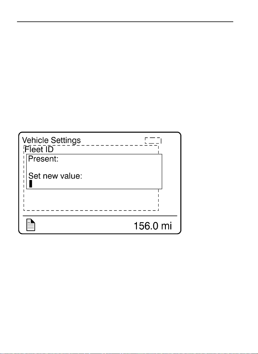
2. Fleet ID
Note: This menu can only be accessed if the correct password has been entered.
The owner can enter the Fleet ID of the vehicle in this menu if required. Data registered in
the engine control unit is then registered for this ID. Enter the new Fleet ID using the up
and down arrows. Enter one number at a time followed by pressing the Enter button. 13
characters must be entered, blank characters are entered in unused positions. The ignition
key must be turned off and back on to update the fleet ID.
W3007382
Page 79
Driver Information Display 71
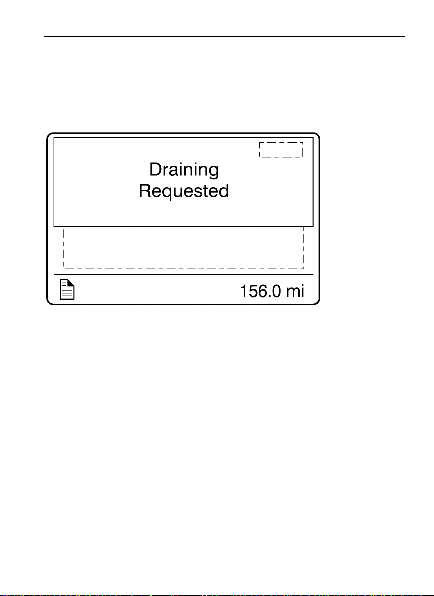
3. Drain Water in Fuel (if equipped)
Press the Enter button to request drain the water in the fuel.
W3007381
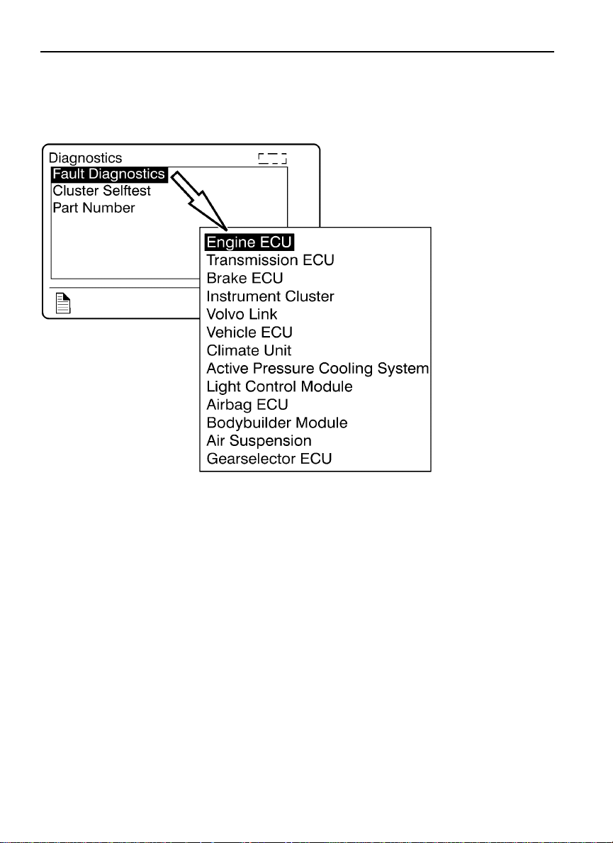
Diagnostics
The Diagnostics menu enables fault tracing on the control units in the vehicle to check for
faults. Instrument tests are available to check the telltales, gauges, display and speaker. The
part number of a control unit can be identified in the part number menu.
Page 80
72 Driver Information Display
1. Fault Diagnostics
A list of the control units on the vehicle is displayed in the Fault Diagnostics menu.
2. Cluster Self Test
There are four sub-menus available:
Telltales test
•
Gauge test
•
Display test
•
Speaker test
•
W3007380
Page 81
Driver Information Display 73
The following table describes the tests. To cancel a test, press the Esc button.
Telltales Test Telltales illuminate for approximately five seconds.
Gauge Test The indicators move forwards and backwards between the end
positions. They do not show any particular value. This is just a
check to confirm that the indicators move, and to make sure the
operators are working.
Display Test The entire display lights up until the Esc button is pressed.
Speaker Test The sound is activated and at the same time, the name of the
selected sound is shown in the DID screen.
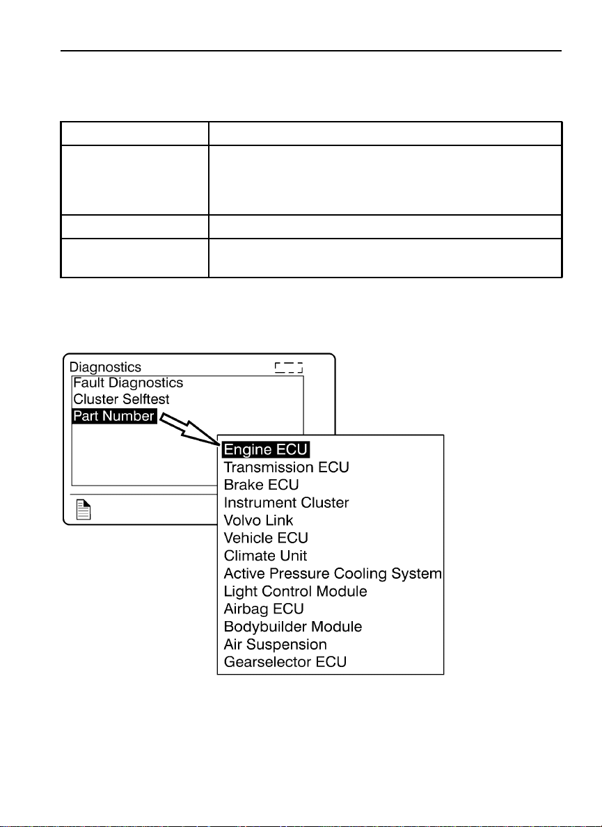
3. Part Number
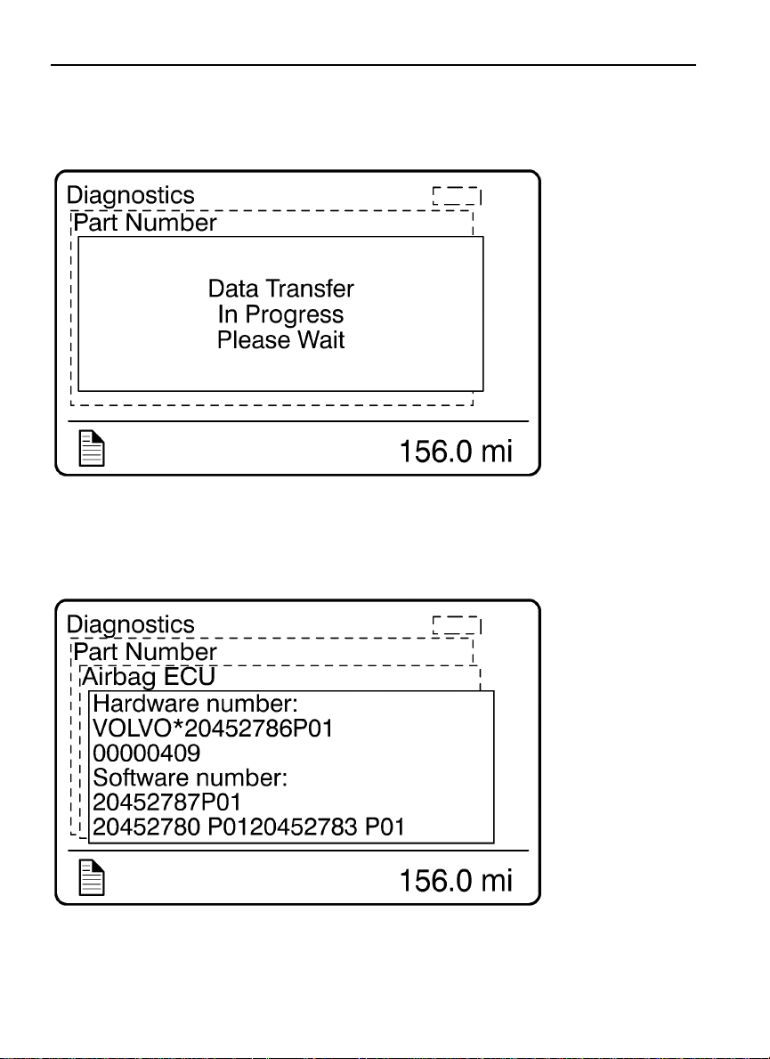
A list of the control units on the vehicle is displayed in the Part Number menu.
W3007379
Page 82
74 Driver Information Display
W3007378
Airbag ECU Used as an Example
W3007377
Page 83
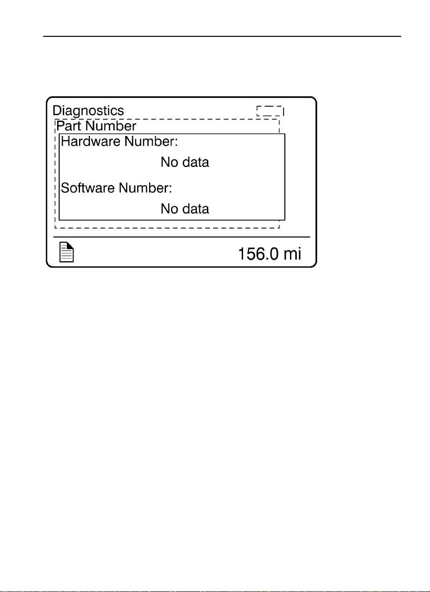
General Diagnostic
Communication Error
Driver Information Display 75
W3007376
Page 84
76 Driver Information Display
Vehicle Data
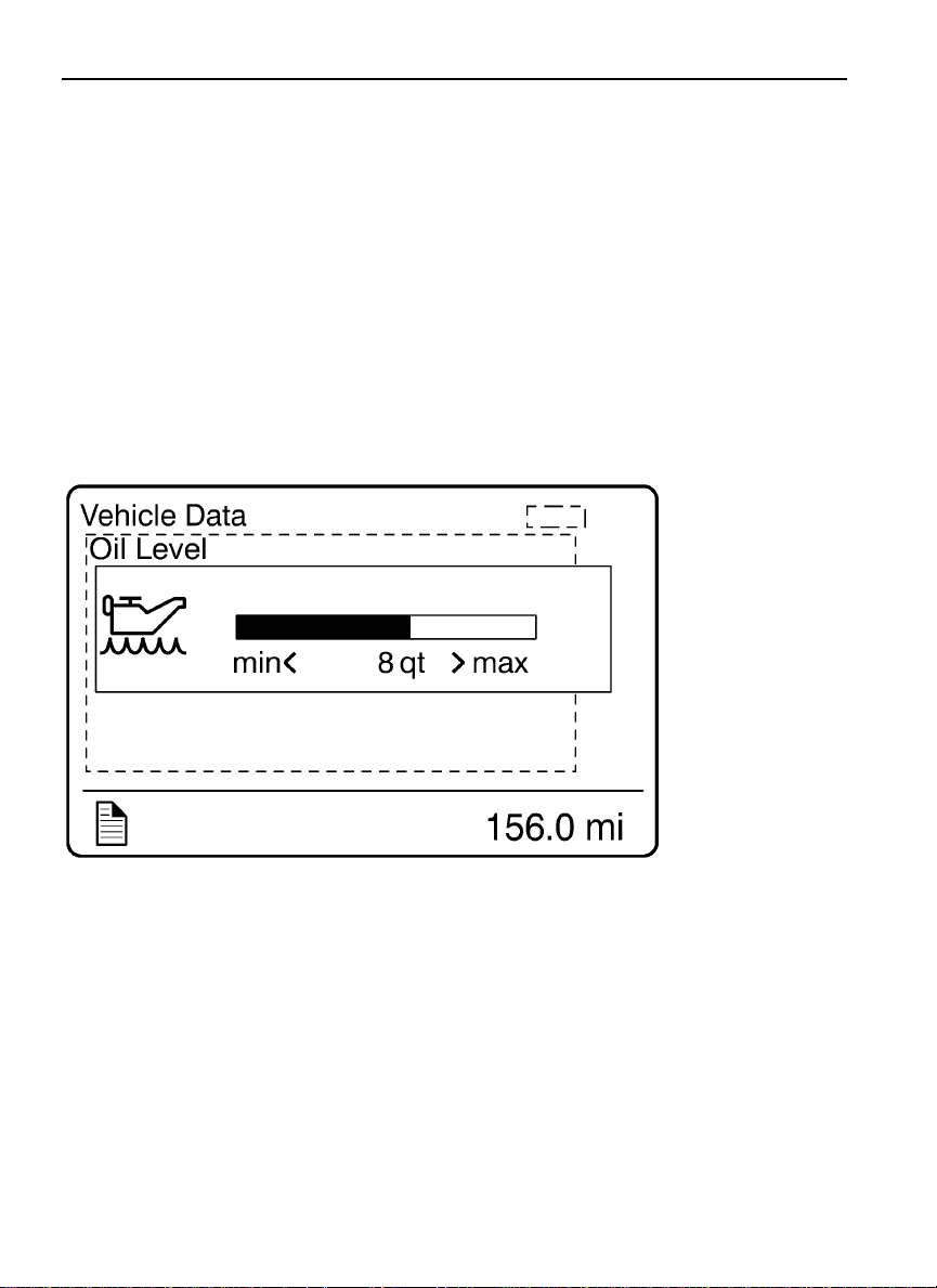
The engine oil level and Maintenance Data can be checked in the Vehicle Data menu.
1. Oil Level (Volvo engines only)
Note: For information about engine oil, refer to the Operator’s Manual VehicleMaintenance.
The vehicle is equipped with an electronic oil level sensor. The bar marked MIN and MAX
shows the engine oil level. The number in the middle indicates the difference between
the MIN and MAX level.
W3007375
Page 85
2. Maintenance Data
Driver Information Display 77
W3029788
Page 86
78 Driver Information Display
Datalog
1. Vehicle ID
W3007374
Page 87
Communication Error
Driver Information Display 79
W3007373
Page 88
80 Driver Information Display
2. Sweet Spot Data
Note: For information about sweet spot data, refer to Performance Bonus Guide in the
vehicle operator’s manual.
W3007372
Page 89
Driver Information Display 81
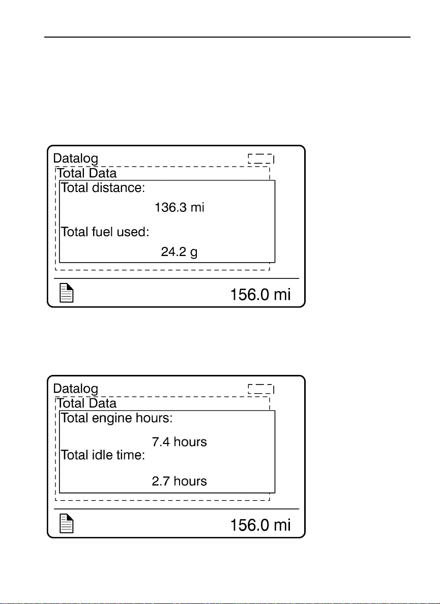
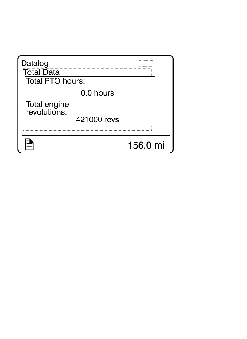
3. Total Data
Totals indicate the accumulated engine values that have been logged during the lifetime of
the engine ECU. Six different totals are stored.
W3007370
W3007369
Page 90
82 Driver Information Display
W3007368
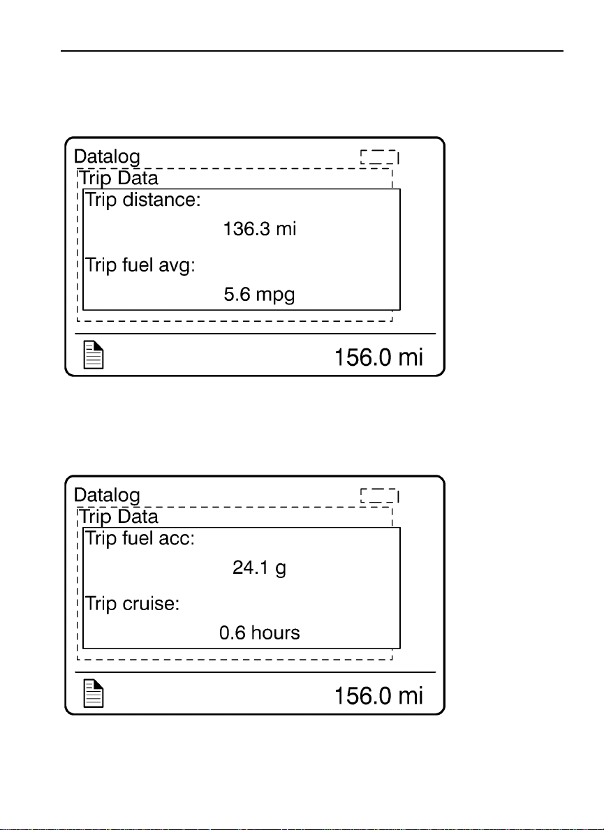
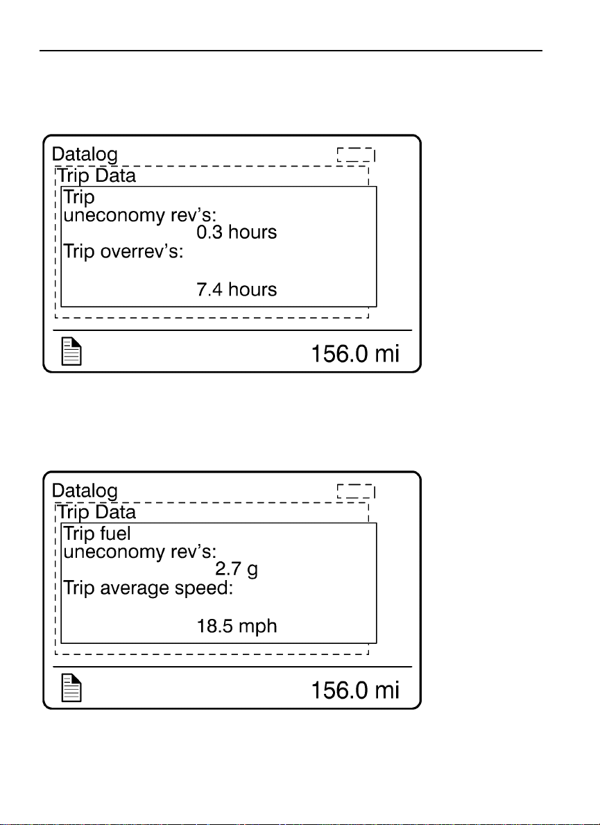
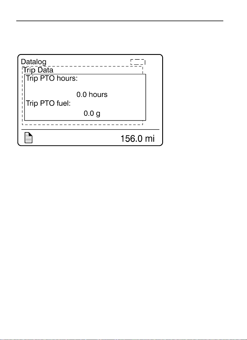
4. Trip Data
Note: Some menus are not available with the Cummins ISX engine.
There are 14 different trip data values stored.
Note: The trip data must be reset before each measurement, see “5. Reset Trip Data”
page 87.
Page 91
Driver Information Display 83
W3007367
W3007366
Page 92
84 Driver Information Display
W3007365
W3007364
Page 93

Driver Information Display 85
W3007363
W3007362
Page 94
86 Driver Information Display
W3007361
Page 95
Driver Information Display 87
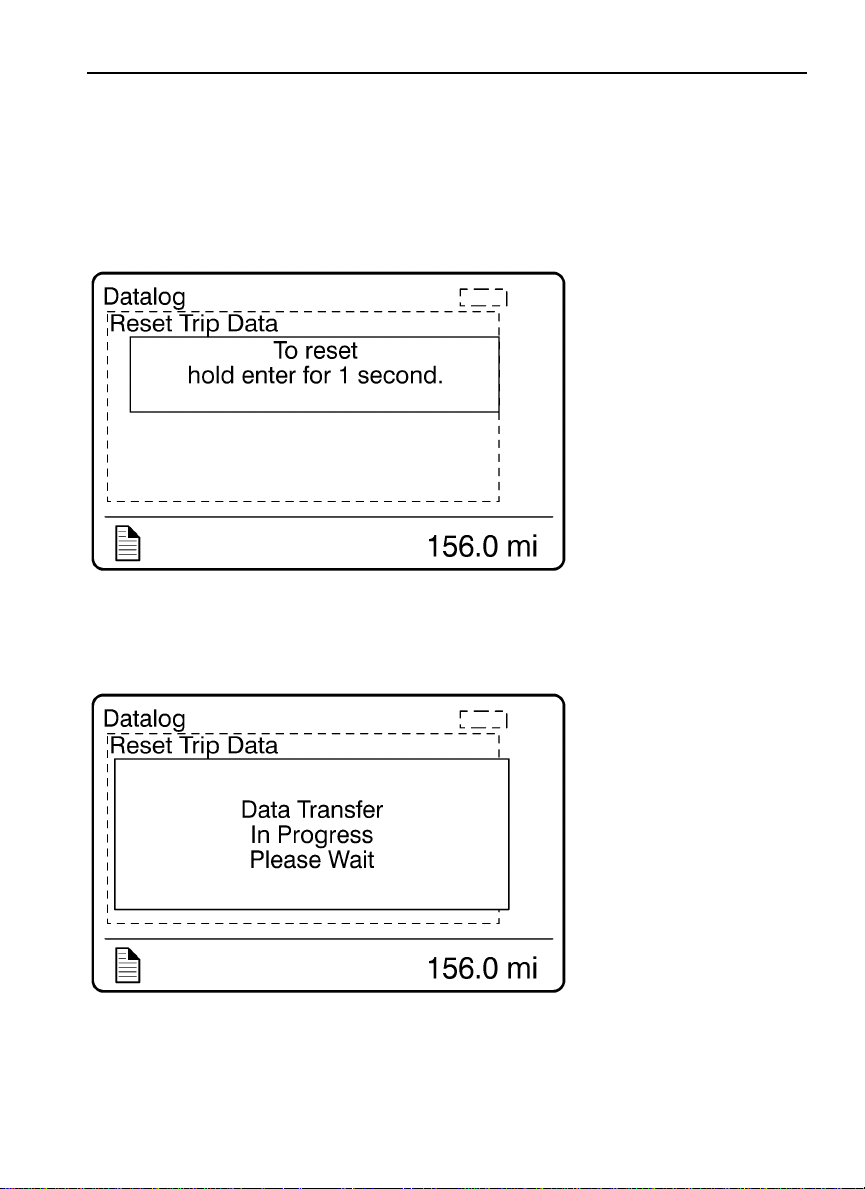
5. Reset Trip Data
Note: This menu can only be accessed if the correct password has been entered.
W3007360
W3007359
Page 96
88 Driver Information Display
W3007358
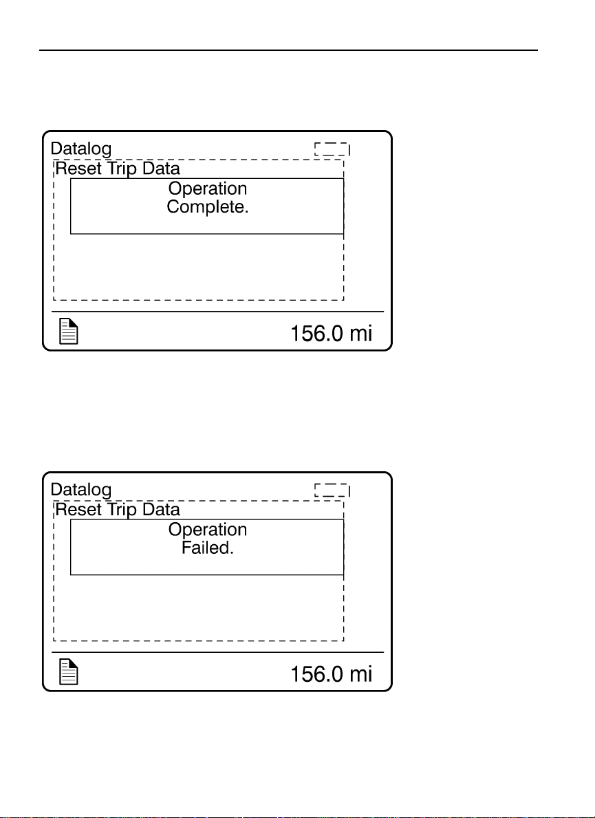
Successful Reset
Unsuccessful Reset
W3007357
Page 97

Driver Information Display 89
Pre-Trip Assistance
The Pre-Trip Assistance option is a tool to assist the driver in completing the pre-trip
inspection of the vehicle. This option is not a substitute for a complete pre-trip inspection.
If any system of the vehicle does not pass inspection, the error must be corrected before
operating the vehicle.
The available pre-trip tests include a Switch/Circuit Status check, Exterior Light Inspection
check, and a Air Leakage check.
Page 98
90 Driver Information Display
Switch/Circuit Status Check
The Switch/Circuit Status check tests the functionality of the switches and their
corresponding circuits. Tostart the check the driver must turn the individual switches on/off.
As the switches turn on/off, the cluster updates the DID to show switch option being tested
and it’s status.
Note: The Hazard and High/Low Switches are momentary switches and return to the OFF
position when released during testing.
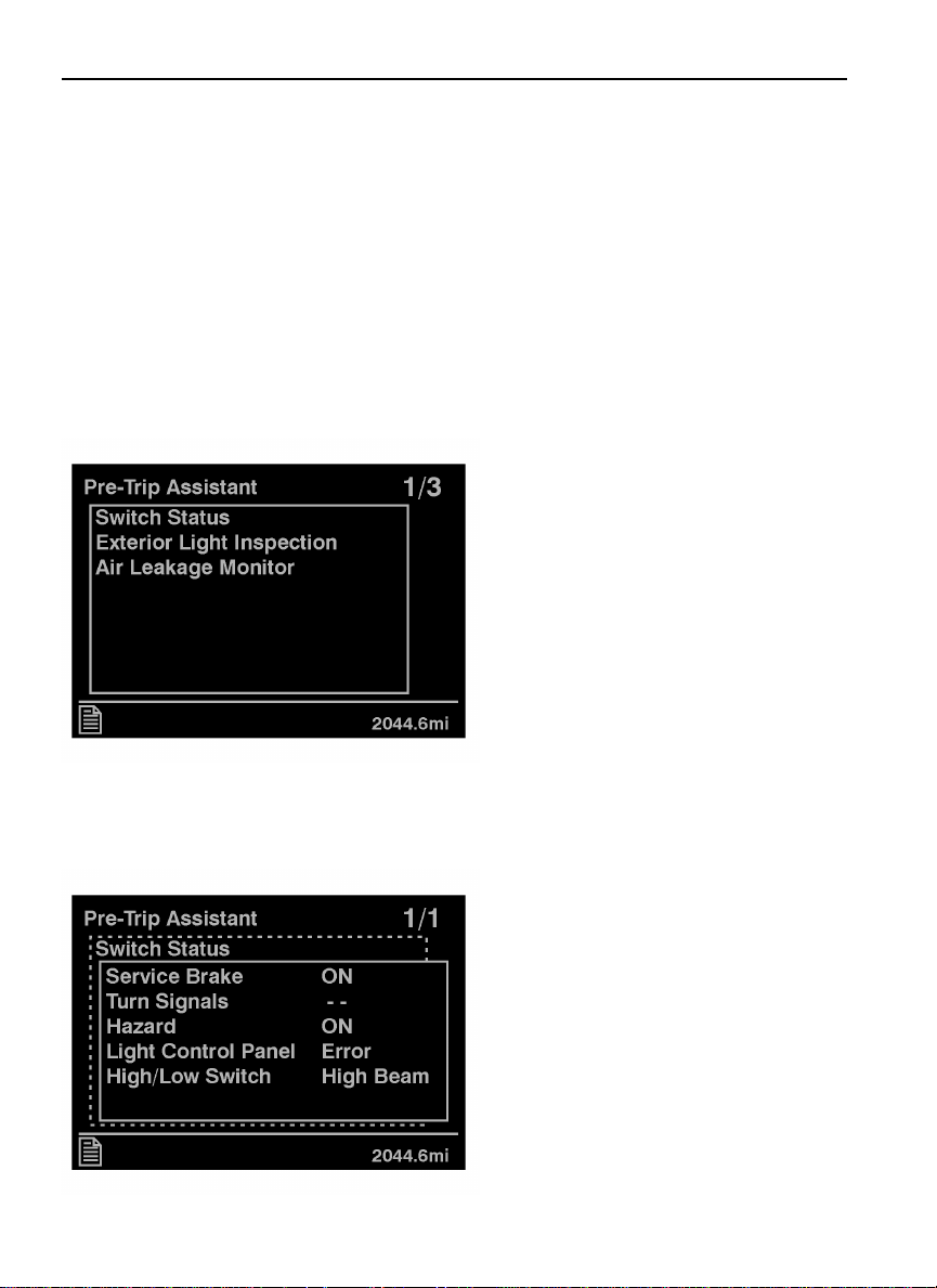
1. The initial Pre-Trip screen displays. Using
the stalk controls, select Switch Status.
W3030322
2.After the diagnostic is completed, the
following screen displays detailing the status
of each switch.
W3030323
Page 99
Driver Information Display 91
Exterior Light Inspection Check
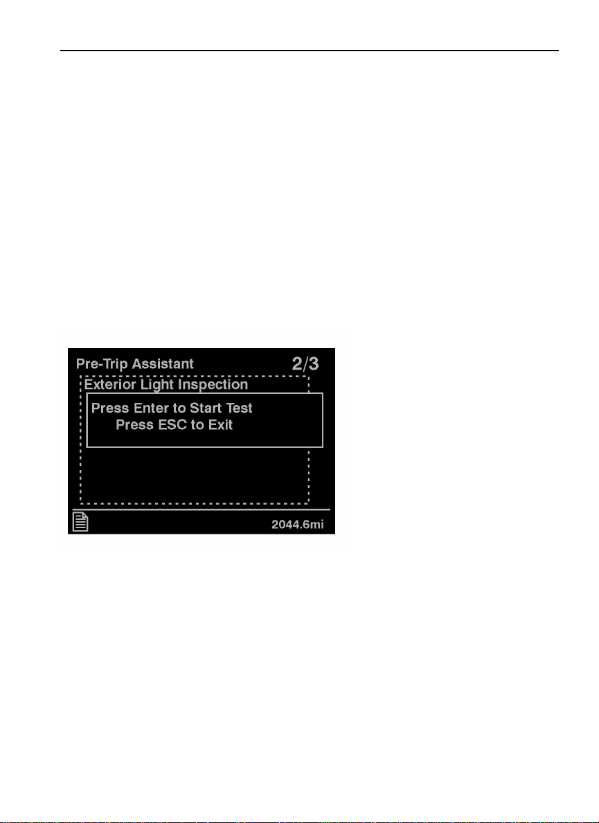
The Exterior Light Inspection check repeatedly turns all exterior lights on/off for the vehicle.
This allows the operator to start the test, exit the vehicle and do a visual check that all
exterior lighting is functioning properly.
The following exterior lights are cycled through the check:
Parking
•
Hazard
•
Turn signals (left and right)
•
High/Low beam headlights
•
Brake
•
Fog/Driving (Optional)
•
1. From the Pre-Trip Assistant main screen
select Exterior Light Inspection.
W3030324
Page 100
92 Driver Information Display
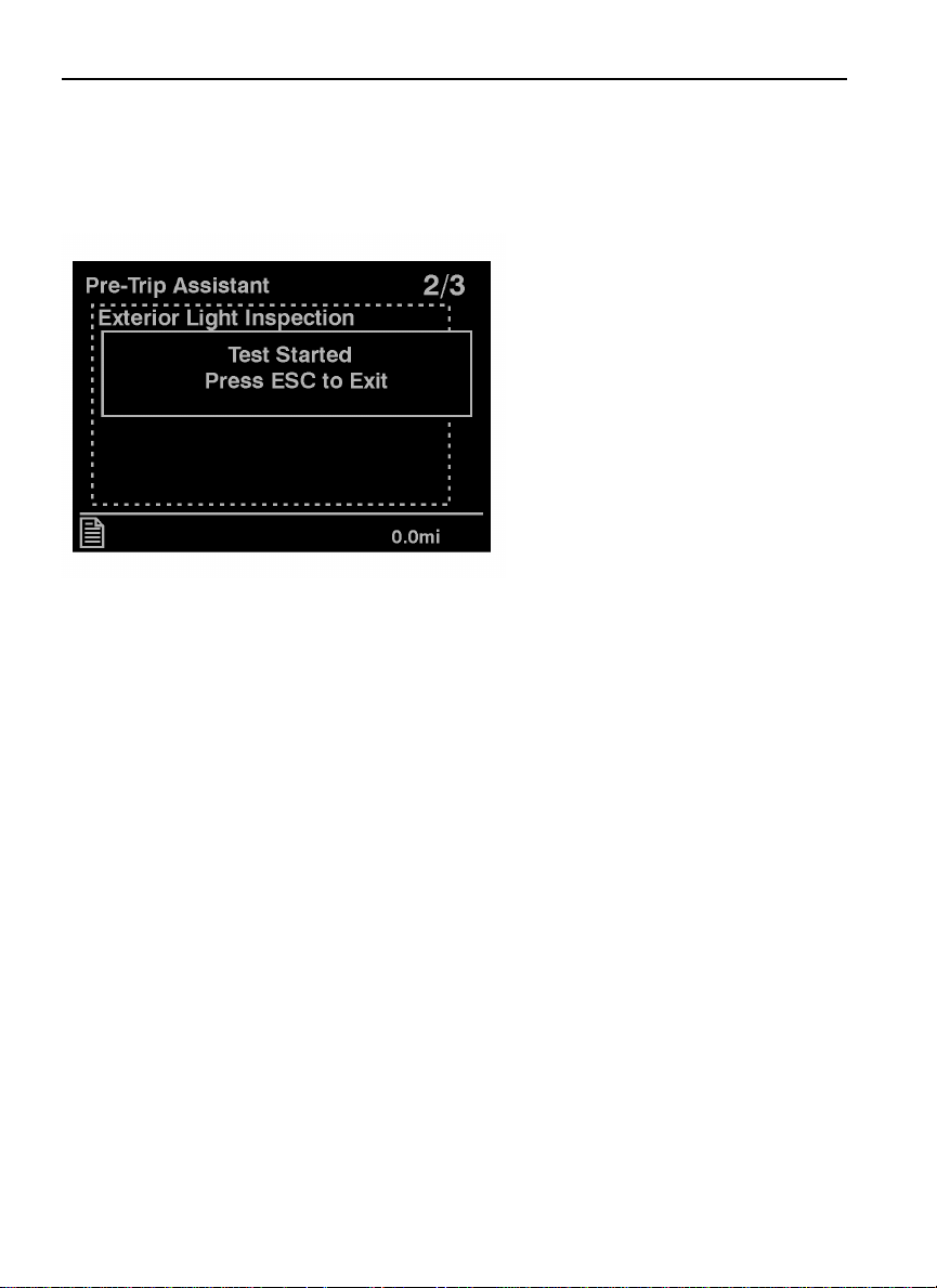
2. The Test Started screen displays. You can
stop the test by pressing ’ESC’ on the stalk
or by starting the ignition.
W3030325
Once the test is started all exterior lights
flash on and off so that you can perform a
visual check.
 Loading...