

Volvo EC330B, EC460B, EC700B, EC360B Service Training
EC330B/EC360B/EC460B/EC70OB SERVICE TRAINING
This material is combined as below.
01_General
02_Engine
02-1_D10B Engine(EC330B-EC360B)
02-2_D12C Engine(EC330B-EC460B)
02-3_D12D Engine(EC330B-EC460B)
02-3_D16E Engine(EC700B)
03_Electric system
03-1_Before IECU application(EC330B-EC460B)
03-2_IECU application(EC330B-EC460B)
03-3_D12D Engine application(EC330B-EC460B)
03-4_EC700B
04_Power Transmission
04-1_Swing motor(EC330B/EC360B)
04-2_Swing motor(EC460B)
04-3_Swing motor(EC700B)
04-4_Travel motor_Old(EC330B/EC360B)
04-5_Travel motor_New(EC330B/EC460B)
04-6_Travel motor(EC460B)
04-7_Travel motor(EC700B)
05_Brake System
06_Steering System
07_Frame & Undercarriage
08_Aircon
09_Hydraulic
09-1_Hydraulic_D10B & D12C(EC330B/EC360B)
09-2_Hydraulic_D12D(EC330B-EC360B)
09-3_Hydraulic_D12C(E460B)
09-4_Hydraulic_D12D(EC460B)
09-5_Hydraulic(EC700B)
09-6_Hydraulic common
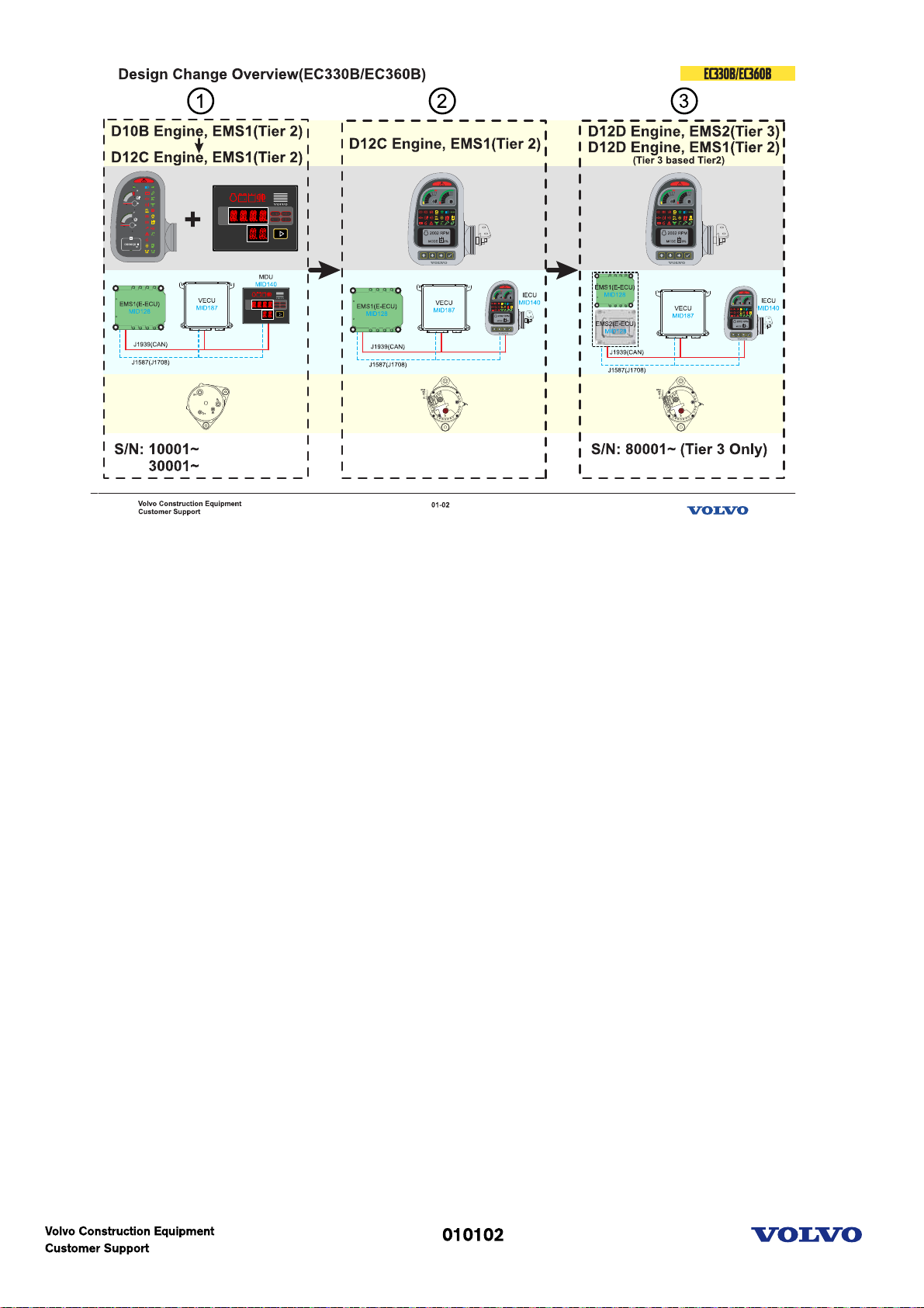
Design Change Overview(EC330B-EC360B)
1-Before I-ECU application
-D10B Engine, EMS1(Tier 2): Initial Production
-D12C Engine, EMS1(Tier 2)
-Instrument panel and MDU
-Old alternator
2-I-ECU application
-D12C Engine, EMS1(Tier 2)
-IECU(Programmable)
-New alternator
3-D12D application
-D12D Engine, EMS2(Tier 3): EU & NA only. Machine serial number starts from 80001
-D12D Engine, EMS1(Tier 3 based Tier 2): International region
-IECU(Programmable)
-New alternator
Picture text:
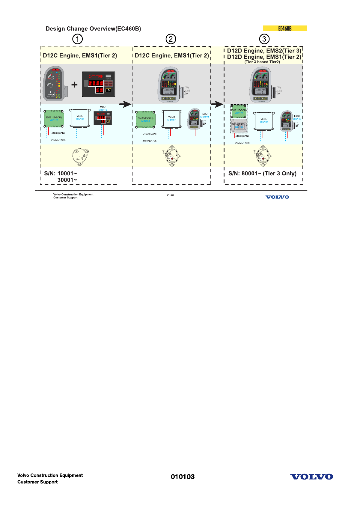
Design Change Overview(EC460B)
1-Before I-ECU application
-D12C Engine, EMS1(Tier 2)
-Instrument panel and MDU
-Old alternator
2-I-ECU application
-D12C Engine, EMS1(Tier 2)
-IECU(Programmable)
-New alternator
3-D12D Engine application
-D12D Engine, EMS2(Tier 3): EU & NA only. Machine serial number starts from 80001.
-D12D Engine, EMS1(Tier 3 based Tier 2): International region
-IECU(Programmable)
-New alternator
Picture text:
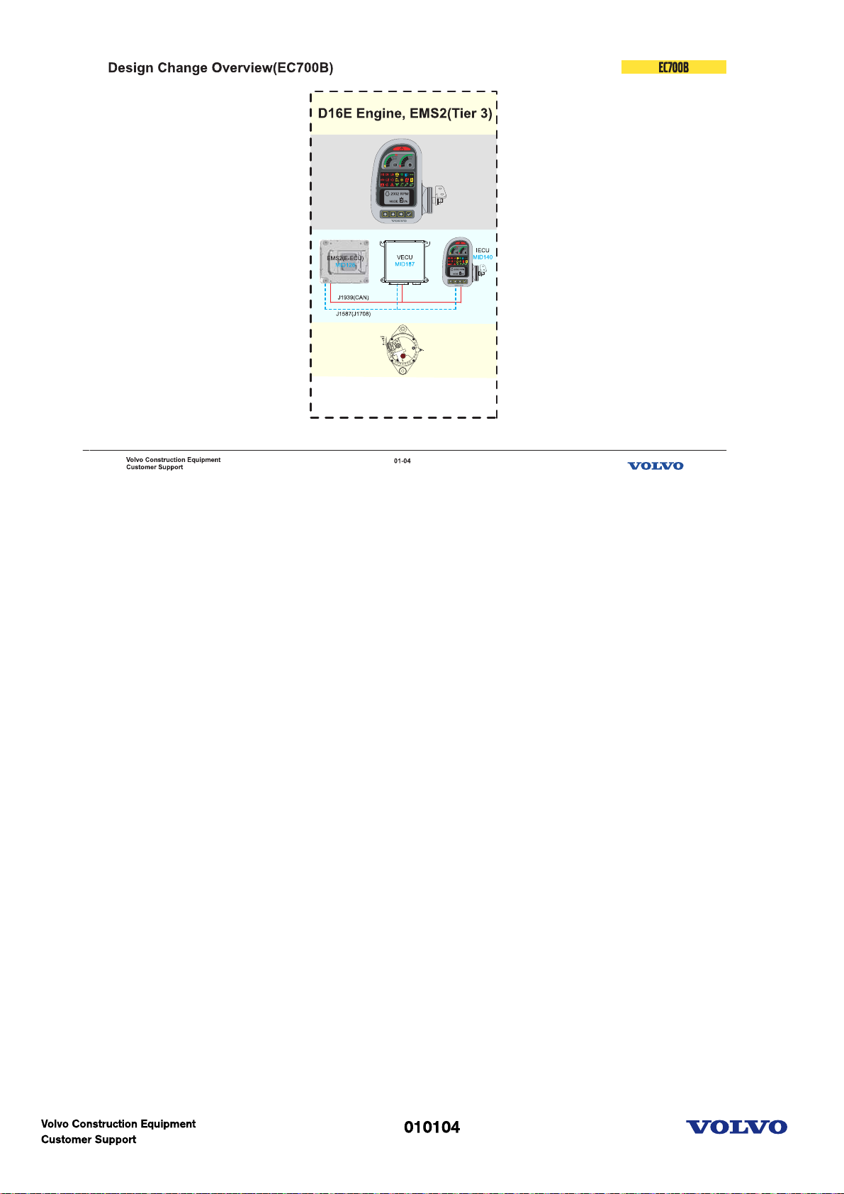
Design Change Overview(EC700B)
-D16E Engine, EMS2(Tier 3)
-IECU(Programmable)
-New alternator
Picture text:
Engine(D10B)
Picture text:
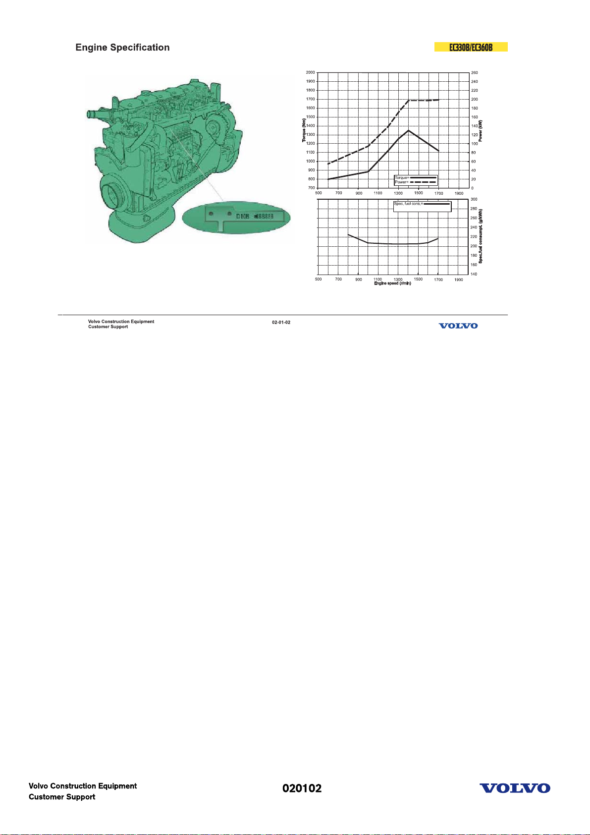
Engine specification
Model: D10B EAE2
Power(kW): 198 at 1700 rpm
Power(hp): 269 hp at 1700 rpm
Torque: 1345 Nm at 1400 rpm
Bore x Stroke: 120.65mm x 140mm
DISPLACEMENT: 9600 cc
Type: 4 cycle-diesel-turbo & charge air cooled
Picture text:
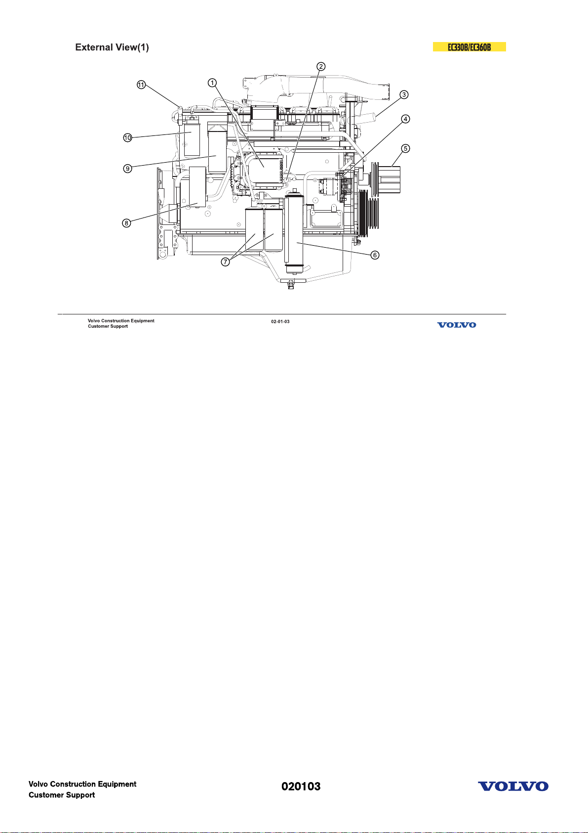
External view(1)
1. EMS(E-ECU)
2. Fuel inlet
3. Water outlet
4. Engine PTO
5. Fan drive & Pulley
6. Engine oil cooler
7. Engine oil filter(full)
8. Breather
9. Engine oil filter(bypass)
10. Fuel filter
11. Fuel feed pump
Picture text:
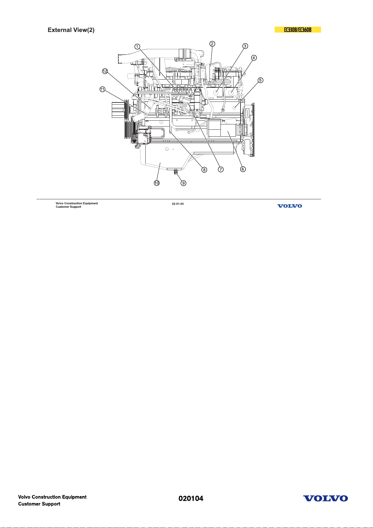
External view(2)
1. Fuel pump
2. Turbochargher
3. Cooler block heater
4. Cab heater supply
5. Coolant filter heater
6. Starter
7. Fuel shut-off solenoid
8. Dipstick
9. Oil drain valve
10. Oil pan
11. Coolant filter return
12. Cab heater return
Picture text:
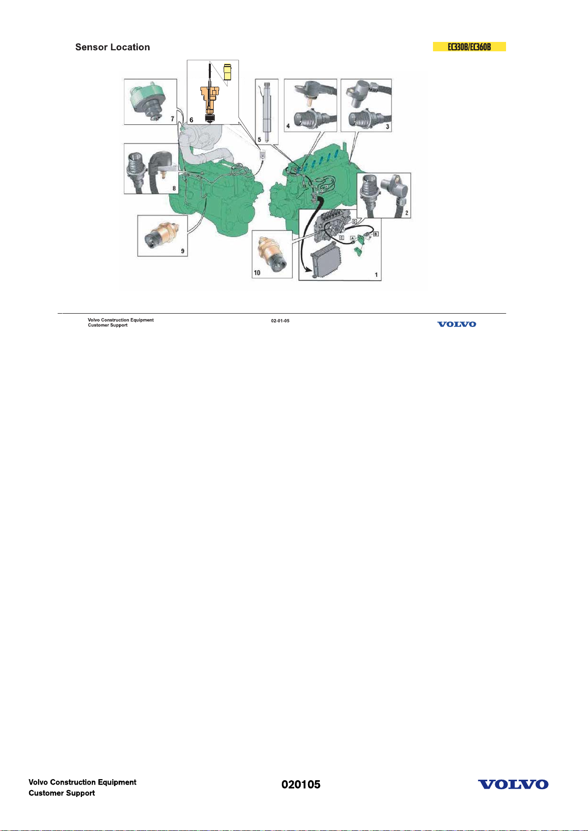
E-ECU Sensors
1. E-ECU
2,3. Speed sensor
4. Coolant temp.
5. Needle movement
6. Coolant level
7. Inlet air press. & temp.
8. Boost air press. & temp.
9. Oil press. & temp.
10. Fuel press. & temp.
Picture text:
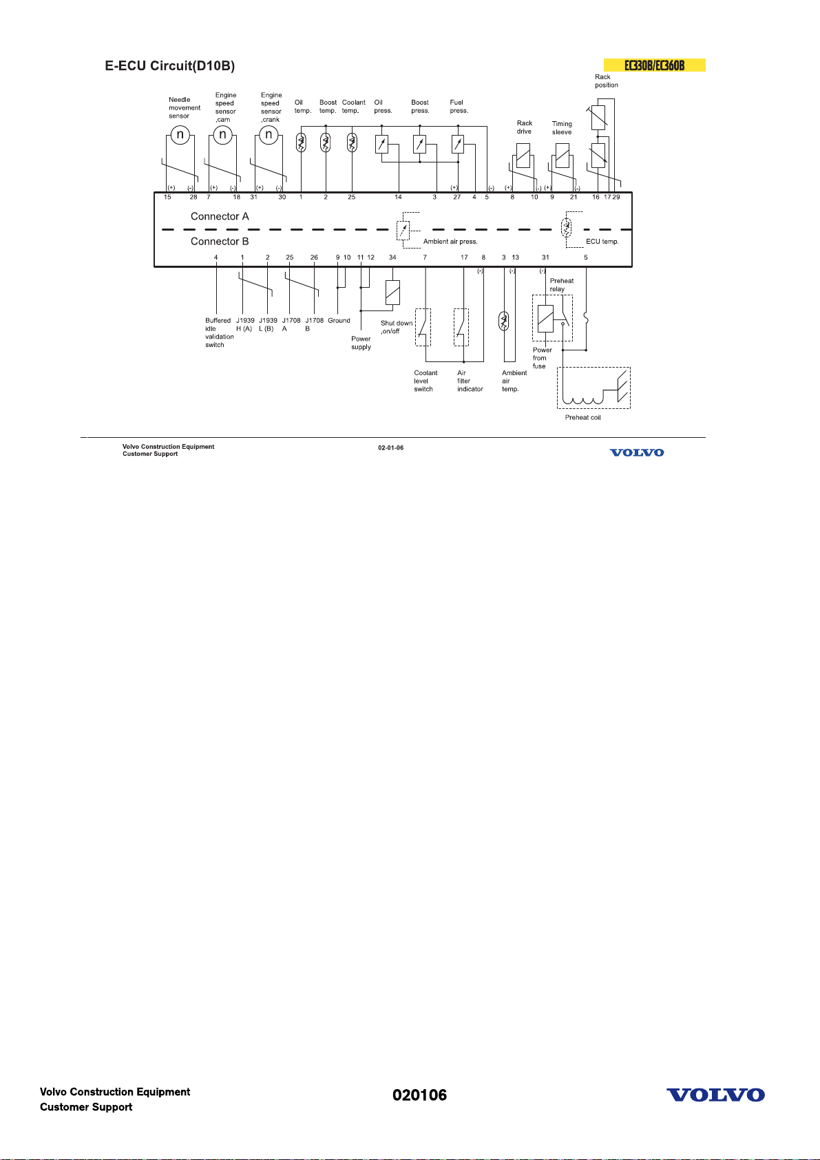
E-ECU circuit
Communication line is at the Red color connector!(Connector B)
Picture text:
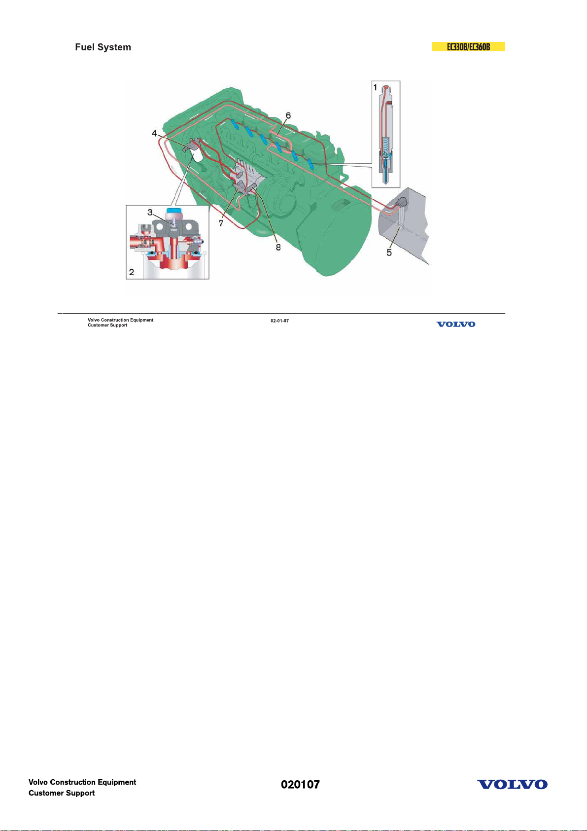
Fuel system
The injection pump is bolted onto a separate bracket on the left side of the engine.The injectors (1) used
are made by Bosch. Their opening pressure is adjusted by means of washers of varying thickness inserted
above the spring.
The fuel filter (2) is attached to a filter bracket. A bleeder nipple is also placed on the bracket (3).
From the feeder pump fuel is forced through the filter and into the injection pump feed side via the fuel
shut-off valve. Return fuel from the injection pump goes via the fuel shut-off valve and overflow valve (8)
to the tank. The leak-off line from the injectors is connected to the injection pump via the suction line
connection.
1. Injector
2. Fuel filter
3. Bleeder nipple
4. Sensor fuel temp/pressure
5. Tank strainer
6. Cooling loop, ECU
7. Feeder pump
8. Overflow valve
Picture text:
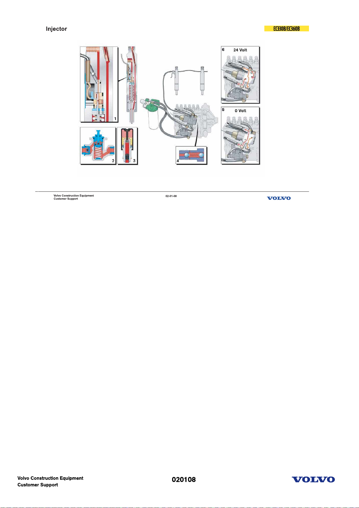
Fuel system-Injector
1 Needle movement sensor
2 Feed pump
3 Manual feed pump
4 Overflow valve
5 Fuel cut-off valve(Off condition)
6 Fuel cut-off valve(On condition)
Picture text:
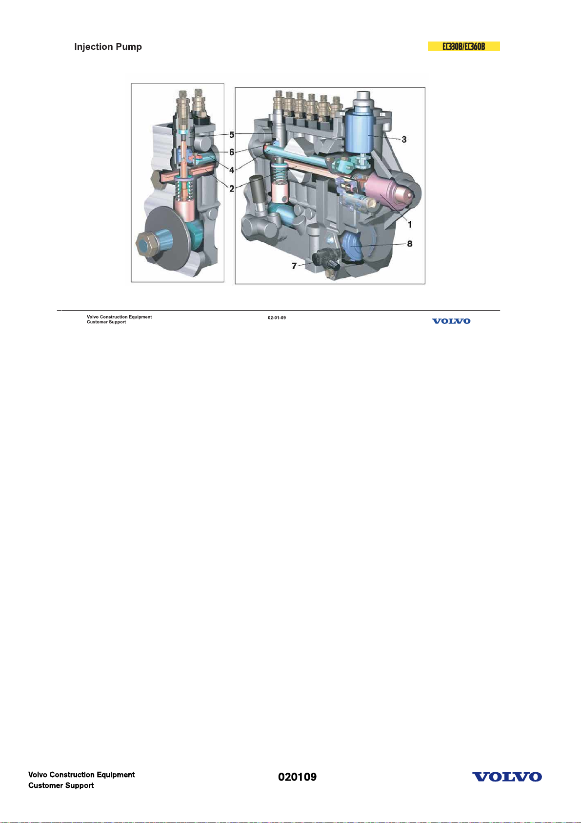
Fuel system-Injection pump
1 Fuel rack control solenoid
2 Fuel rack(injection quantity control)
3 Injection timing control solenoid
4 Lever
5 Delivery valve
6 Timing sleeve
7 Speed sensor
8 Toothed wheel
Picture text:

Fuel system-Injection control
Injection timing is adjusted by timing sleeve location.
Injection quantity is adjusted by fuel rack operation.
Picture text:
Engine(D12C)
Picture text:
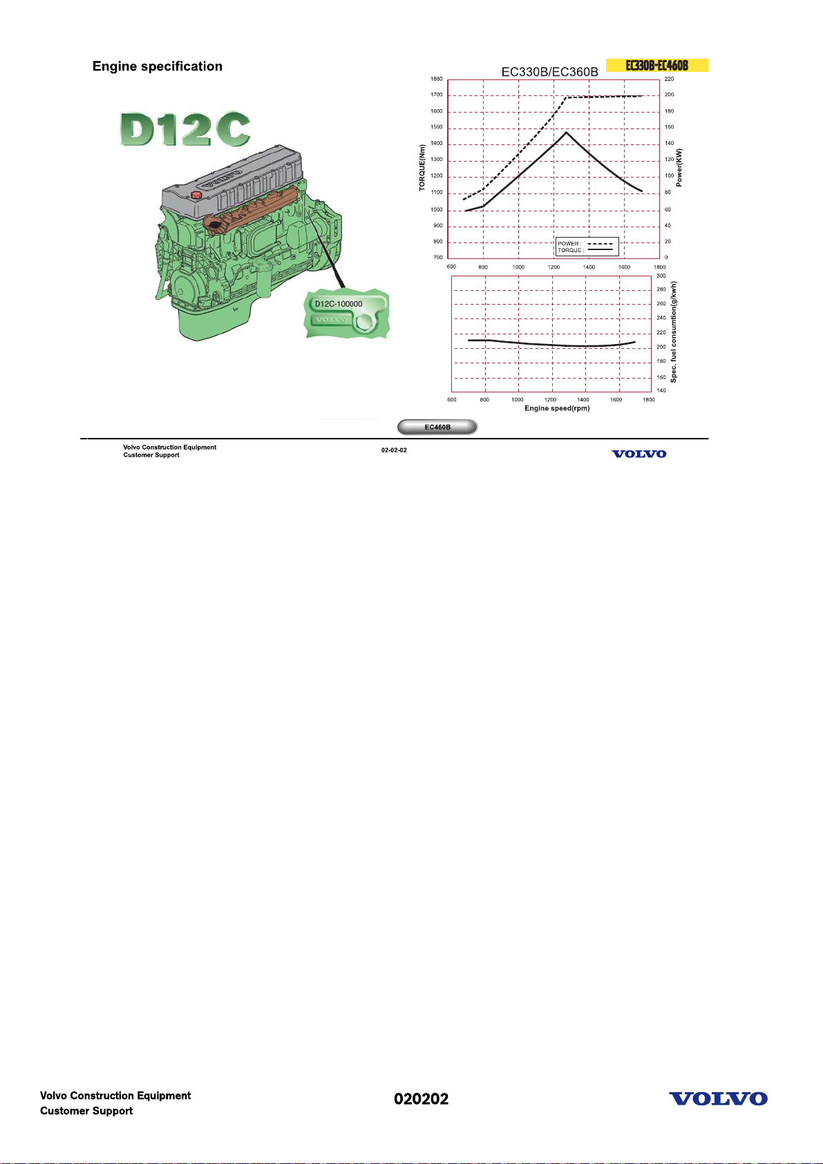
Engine specification
D=Diesel engine
12=Cylinder volume in litres
C=Generation
E=Excavator application
C=Version
E2= Valid to Tier-2 & Euro-2
1. EC330B-EC360B
D12CECE2(For NA), D12CEDE2(For EU), D12CEEE2(For other region)
Power: 198Kw at 1700rpm
MAX Torque: 1345Nm at 1400rpm
2. EC460B
D12CEAE2(For NA), D12CEBE2(For EU), D12CEFE2(For other region)
Power: 239Kw at 1900rpm
MAX Torque: 1600Nm at 1400rpm
D12 is the model number of the volvo 12 liter engine.
The engine is a 6-cylinder, 4-stroke, direct injection diesel with a 12 liter cylinder volume, turbocharger,
charged air cooler and electronic controlled fuel injection, EMS (Engine Management System).
The serial number of the engine is to be found stamped in the cylinder block on the rear left side.
The cylinder head is of cast iron and manufactured in one piece which is necessary in order to provide
stable bearings for the overhead camshaft.
The cylinder liner is sealed against the coolant casing with rubber rings.
The D12C has a four-valve system and overhead camshaft.
The engine timing gear transmission is located at the front of the engine on a 10 mm thick steel plate
bolted to the cylinder block.
The crankshaft is drop forged and has induction hardened bearing surfaces and fillets.
The engine is force fed lubricated by an oil pump which is gear driven from the engine crankshaft via an
intermediate gear
The fuel system for D12C has electronic control with unit injectors one for each cylinder and which operate
at a very high pressure.
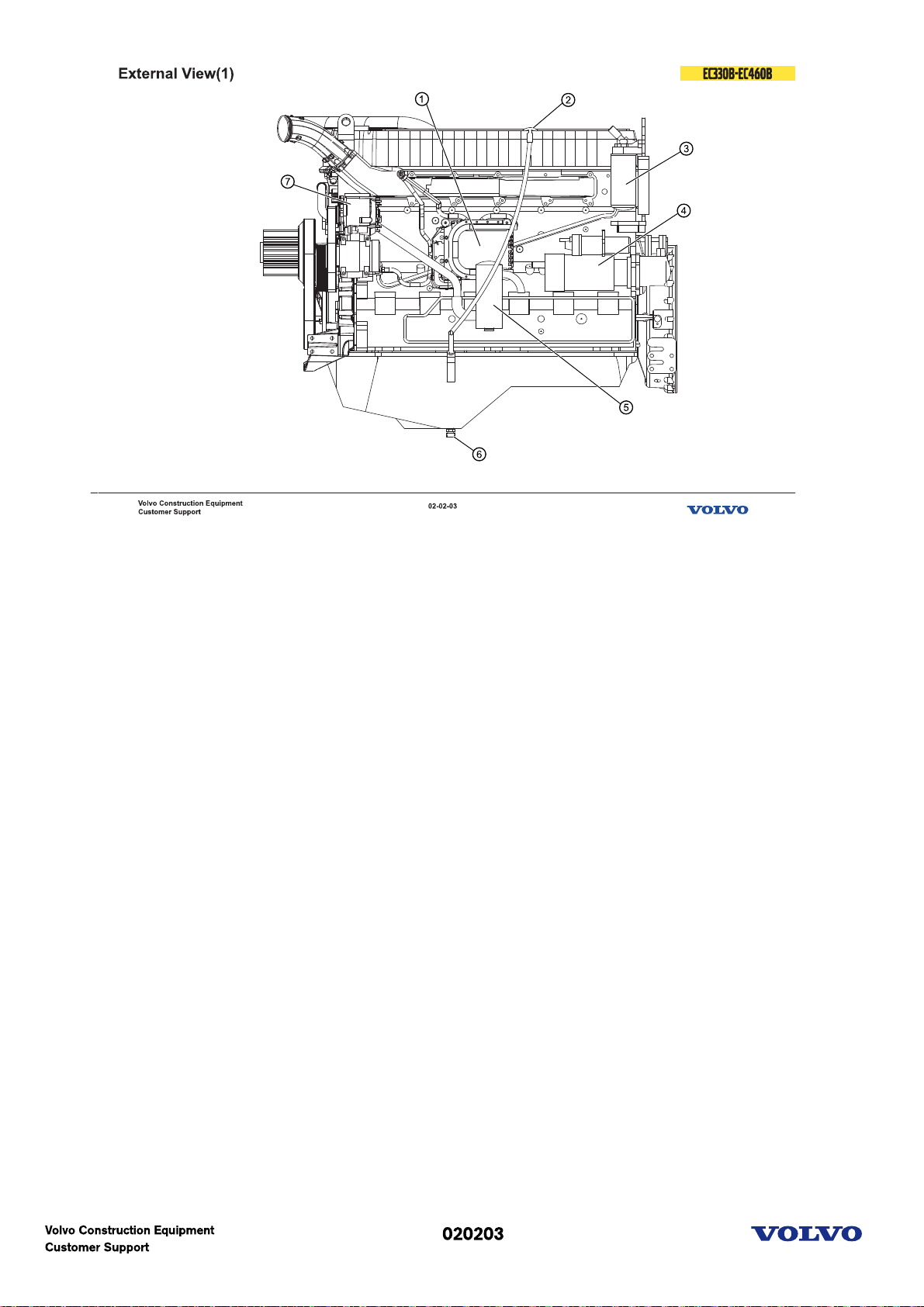
External view(1)
External view & component location
1. E-ECU
2. Dip stick
3. Fuel filter
4. Start motor
5. Breather
6. Oil drain valve
7. Alternator
Picture text:
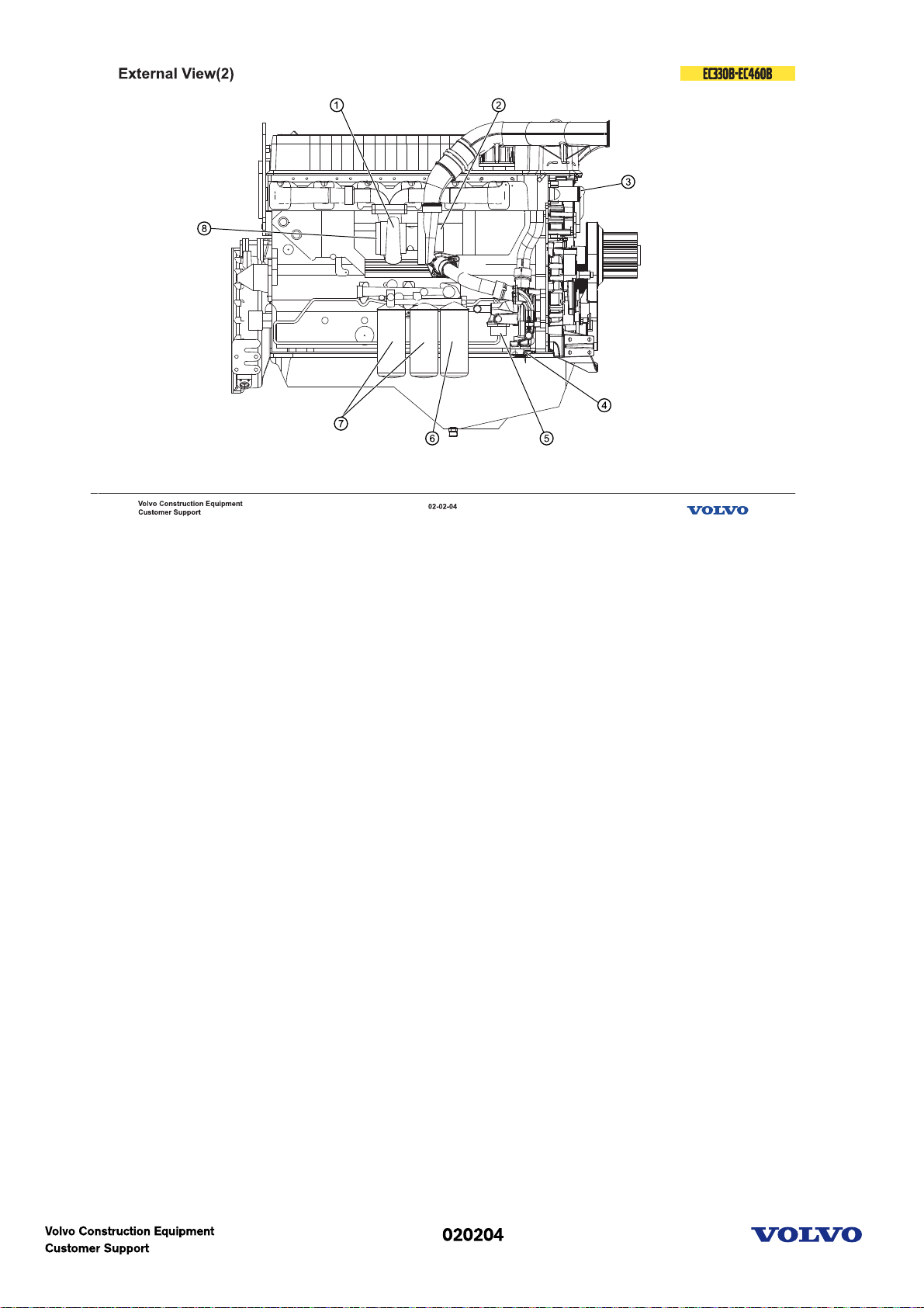
External view(2)
External view & component location
1. Turbocharger
2. Air inlet
3. Water outlet
4. Coolant filter connection
5. Water inlet
6. Oil filter(by-pass)
7. Oil filter(full flow)
8. Exhaust outlet
Picture text:
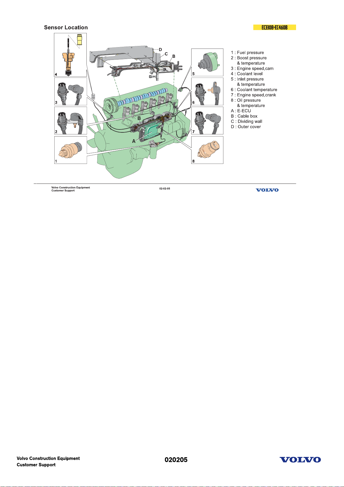
E-ECU Sensors
The D12C has a total of eight sensors. Three of these have dual functions. This gives a total of 11
functions.
The dual function sensors are:
2 Turbo boost pressure/air temperature in inlet manifold.
5 Air temperature before intercooler and pressure drop indicator. Located in the union pipe between the
air filter housing and the turbocharger inlet.
8 Oil pressure/temperature.
The other sensors are:
1 Fuel pressure sensor. Senses the pressure after the fuel filter.
3 Camshaft position sensor. Located in the upper timing mechanism cover.
4 Engine coolant level. Located in the expansion tank.
6 Engine coolant temperature. Located in the rear end of the cylinder head.
7 Engine speed sensor. Located in the fly wheel cover.
Apart from the sensors above, the system includes a sensor for Atmospheric Pressure, located inside the
EECU.
Picture text:
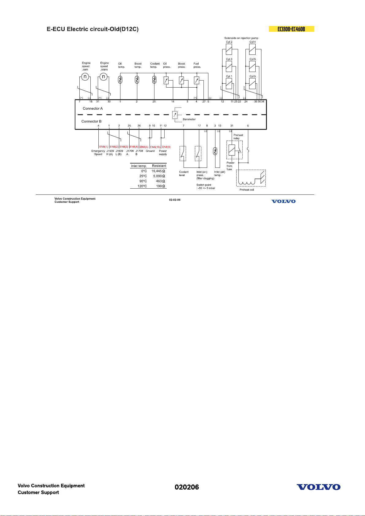
EECU electric circuit(Old)
Communication between the control units go via two data buses.
The two data buses have different functions. One is used for the control signals of system and is
designated SAE J1939.
The other databus, SAE J1708, is used for information and diagnostics. The link also functions as a back
up for the other databus if this for any reason does not function.
The Engine Management System (EMS) consists of a control unit (EECU) mounted to the engine, sensors
and a wiring harness. The EECU, Engine Electronic Control Unit, is connects to both the data bus SAE
J1939 and SAE J1708.
The unit receives signals from the Vehicle Control Unit, VECU.
It sends signals to control various functions on the engine and communicates with other control units via
the databuses.
Picture text:
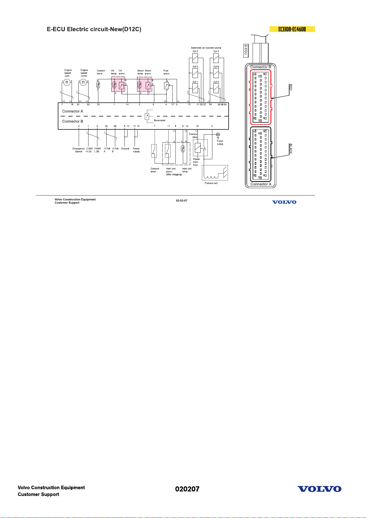
E-ECU Electric circuit(New)
New sensor
1. Oil temp. & oil pressure sensor
2. Boost temp. & boost pressure sensor
Picture text:
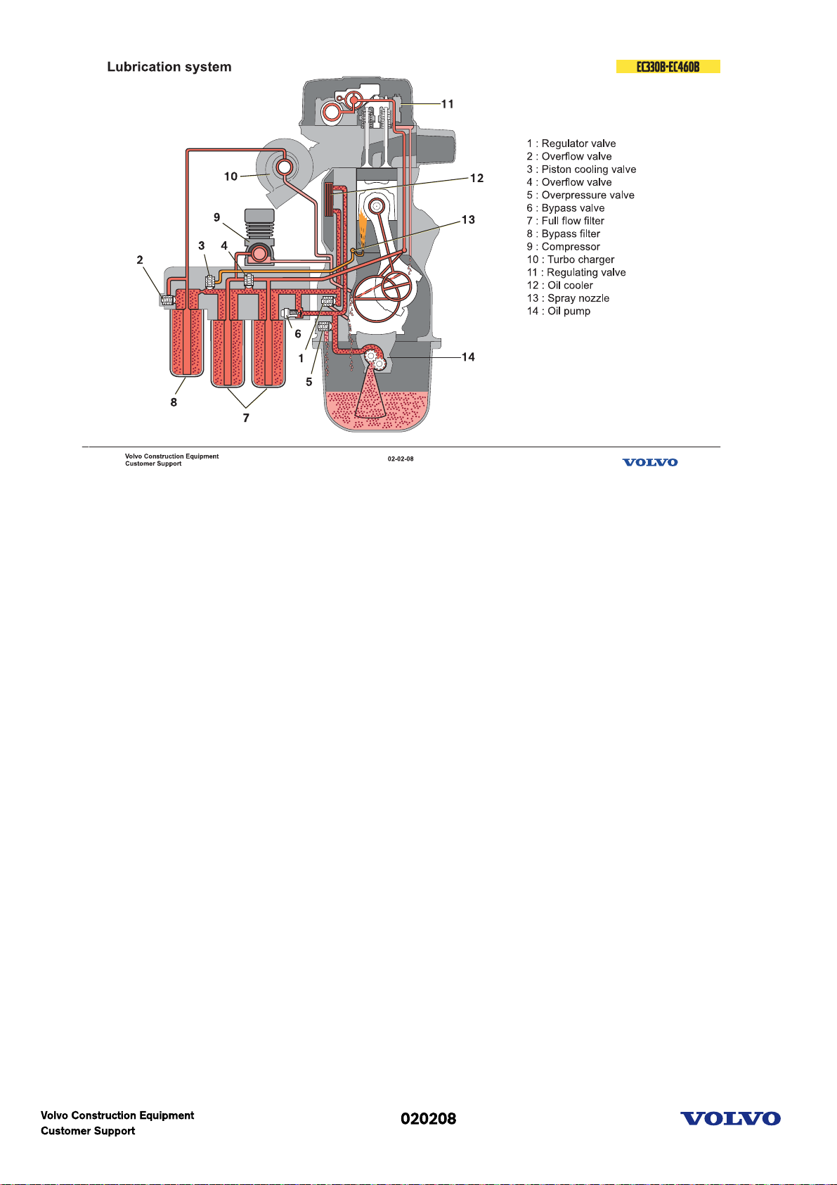
Lubrication system schematic
This is a schematic description of the lubricating system.
When the engine starts the gear driven pump forces the lubricating oil in to the filter housing. At low oil
temperature, for example when cold starting in the winter the bypass valve for the oil cooler will open so
the oil will reach the engine faster. From the full flow filters the oil is distributed to the bypass filter and
the engine block gallery then to all the engine lubricating points.
The turbo charger is lubricated with oil directly from the bypass filter.
The air compressor is lubricated via an external hose from the filter housing.
Oil return from the cylinder head
There are three oil return holes drilled through the cylinder head and block.
Oil pressure reducing
The regulator valve regulates the engine oil pressure and excess oil is led back to the sump.
Piston cooling
The valve for piston cooling is pressure sensitive and opens just above the normal idling pressure. The oil
is led in to the lengthways channel in the block and sprayed via nozzle, one for each piston, onto the
inside of the piston.
By-pass filter Overflow
The overflow valve for the bypass filter opens if the filter becomes blocked to ensure turbo lubrication.
Full flow filter Overflow
The overflow valve for the full flow filter opens if the filter becomes blocked to ensure engine
lubrication. Oil cooler bypass
When the engine starts and the oil temperature is low (low viscosity), the oil cooling bypass valve opens.
This is to lubricate the engine faster during cold start. When the oil temperature is stabilized (viscosity)
the valve closes and the oil passes through the oil cooler.
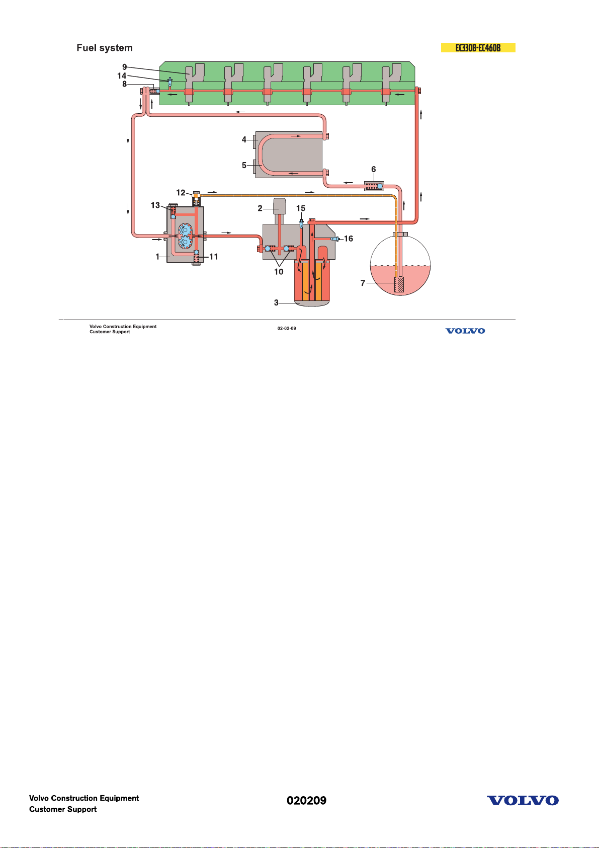
Fuel system principle
The fuel flow and valve function is schematically described. Light red means suction and dark red means
feed pressure.
The fuel is sucked up by the feeder pump (1) through the strainer (7) in the tank fitting, past the nonreturn valve (6).The non-return valve opens and the fuel flows to the control unit and goes through the
cooling loop (5) ( if the control unit (4) has cooling ) up to the overflow valve (8) and from there, together
with the return fuel which passes through the overflow valve to the feeder pump suction side.
The feeder pump (1) forces the fuel to the filter housing, past both of the non-return valves (10) for the
hand pump (2) and at the same time valve (12) opens for the return fuel to the tank. If there is some air
in the system it will automatically be bleeded.
After through the filter (3), to the cylinder head lengthways channel to feed the injectors (9).
The overflow valve (8) maintains a constant pressure for the fuel feed to the injectors (9) and opens at the
pressure of 3,5 to 4,5 bar.
The pressure regulating valve (11) in the pump opens to reduce the pressure in the pump for example
during engine braking when the fuel injection is cut off.
Picture text:
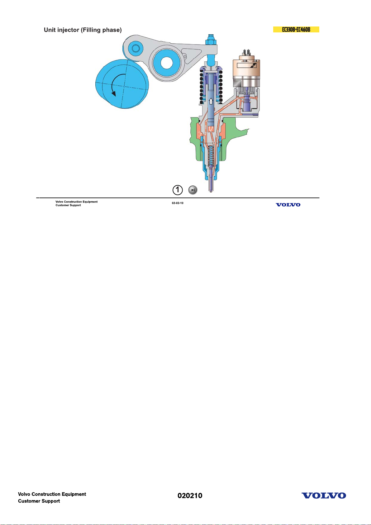
Unit injector
The unit injector
The unit injector is driven by the engine camshaft via a rocker arm. Simply put, a unit injector is a
combination of an injection pump and a conventional injector and it consists of three main sections:
the pump section(1)
the valve section with the solenoid(2)
the injection section(3)
The pump piston pumps a constant quantity of fuel back and forth through the injector and there is no
injection as long as the injector solenoid keeps the valve open.
1. Filling phase
This occurs the entire time that the pump piston is on the way up. The fuel valve is open since there is no
voltage applied to the solenoid valve. Fuel can therefore be sucked from the feeder channel, past the
open valve and into the pump cylinder.
2. Spilling phase
The pump piston is on the way down. As long as there is no voltage to the solenoid valve, the fuel valve is
open and the fuel flows back in return to the feeder channel.
3. Injection phase
The pump piston is still on the way down. Now the solenoid valve has received voltage from the control
unit. The valve cone is lifted and the valve closes. Since fuel cannot pass through the valve, a pressure is
quickly built up which lifts the nozzle needle and injection occurs.
Injection continues as long as the valve is closed and the pump piston is on the way down.
The injection timing and fuel quantity is determined by the length of the electrical pulse. It is the control
unit which determines the pulse size via the information it receives from the control system.
4. Pressure reducing phase
The pump piston is still on the way down. The control unit ends the electrical pulse when the engine has
received the amount of fuel needed at that instant. The fuel valve opens and the fuel can once again flow
past in return to the feed channel. The pressure then drops quickly and the nozzle needle closes.

Engine(D12D)
Picture text:
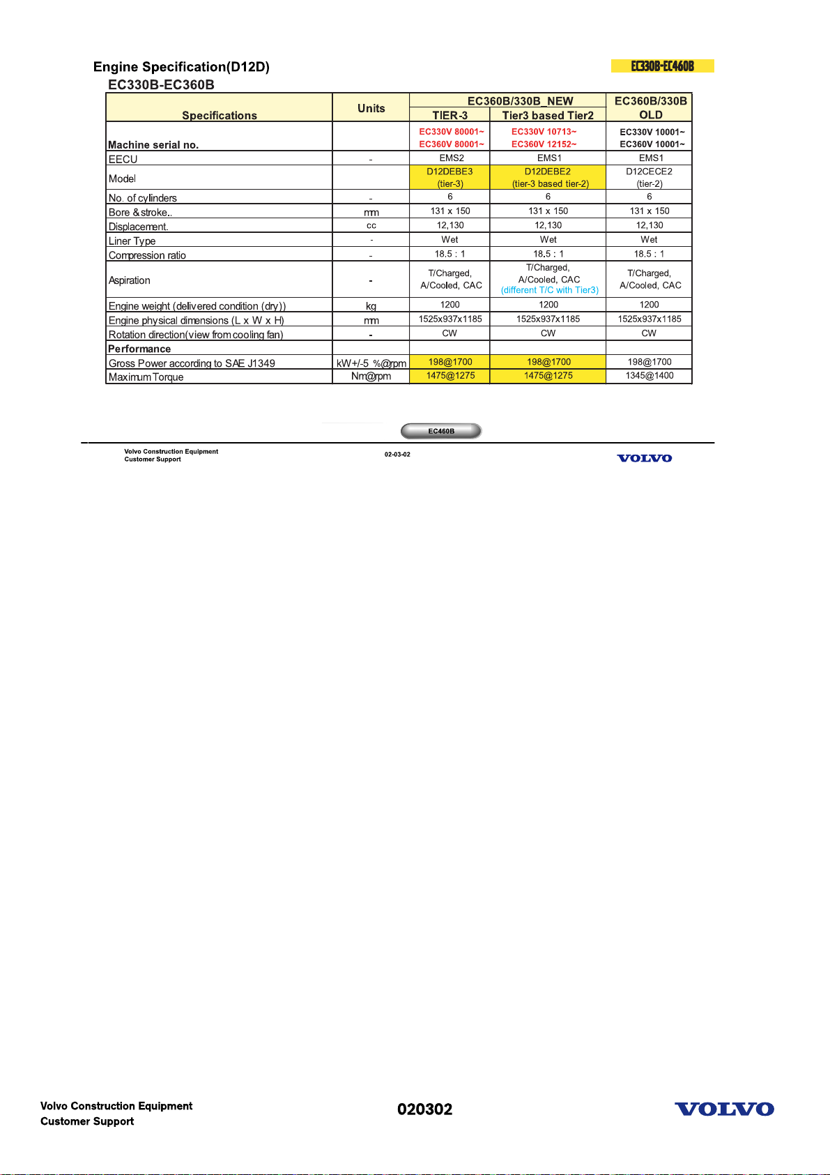
Engine specification (D12D)
EC330B-EC360B
Excavator uses the D12DEBE3 & D12DEBE2.
For those 2 engines, external layout (fuel line, cooling, inlet & exhaust, mounting) is almost same but
internal components (ECU, Unit injector, Piston etc.) are totally different.
Machine with D12DEBE3 has new serial number started with 80001 and will cover EU & NA region.
EC460B
Excavator uses the D12DEAE3 & D12DEAE2.
For those 2 engines, external layout (fuel line, cooling, inlet & exhaust, mounting) is almost same but
internal components (ECU, Unit injector, Piston etc.) are totally different.
Machine with D12DEAE3 has new serial number started with 80001 and will cover EU & NA region.
Picture text:
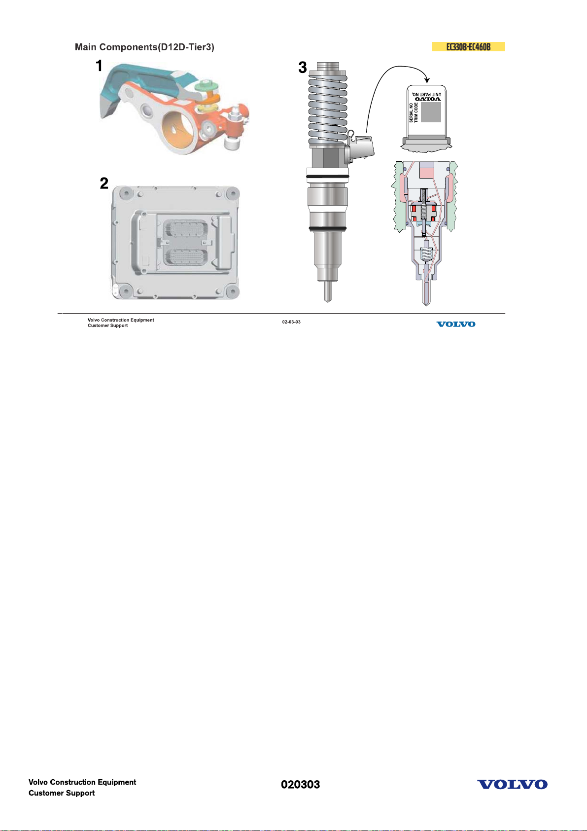
Main components
1.The IEGR double rocker has an extra arm, the follower arm, which creates a small second exhaust valve
lift. This extra lift feeds exhaust gases back into the cylinder during the inlet stroke.
2.The most advanced Volvo engine controller, EMS2, will be utilized to provide the highest level of
electronic features and to enhance reliability.
3.The proven new high-pressure dual solenoid diesel fuel injector, Delphi E3, introduced with the Volvo
U.S. EPA 2002 highway engine, is an integral part of the V-ACT (Volvo Advanced Combustion Technology)
system.
**When replacing the injector, we need parameter programing for trim code with VCADS Pro.
Picture text:
1. Switch Able Internal EGR Double Rocker
2. Engine Management System Controller EMS2
3. High-pressure dual solenoid fuel injector Delphi E3
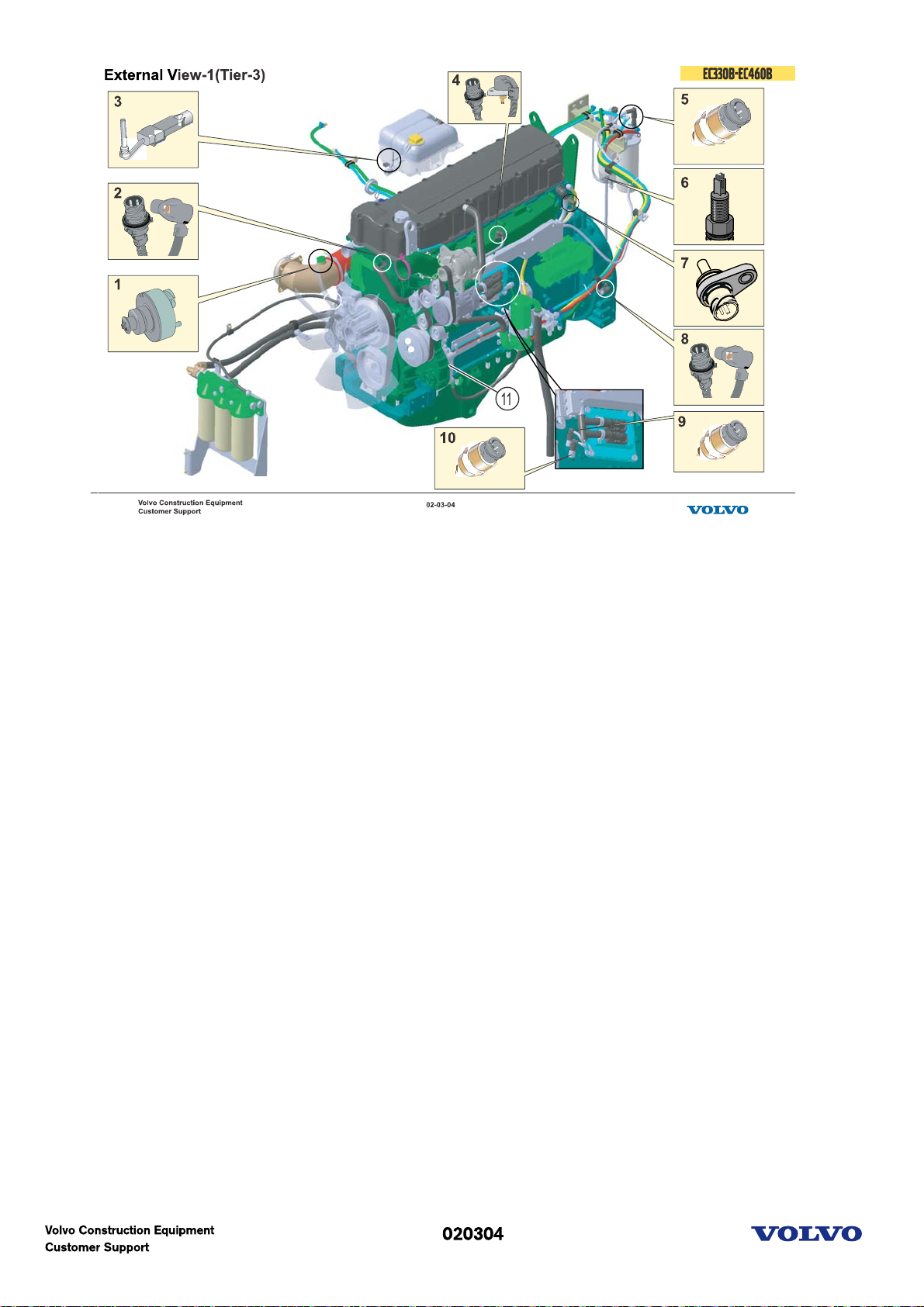
External view-1(Tier-3)
1. Inlet air temp. & pressure sensor
2. Cam speed sensor
3. Coolant level sensor
4. Boost press. & temp. sensor
5. Fuel feed pressure sensor
6. Water in fuel sensor
7. Coolant temp. sensor
8. Crank speed sensor
9. Engine oil press. sensor
10. Crankcase pressure sensor
11. PTO
Picture text:
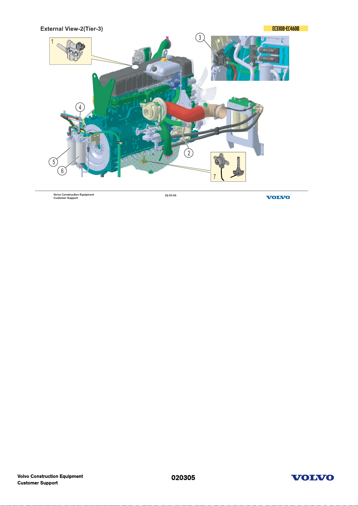
External view-2(Tier-3)
1. IEGR solenoid
2. Coolant pump
3. Fuel feed pump
4. Fuel lift pump
5. Fuel filter
6. Water seperator
7. Engine oil level & temp. sensor
Picture text:
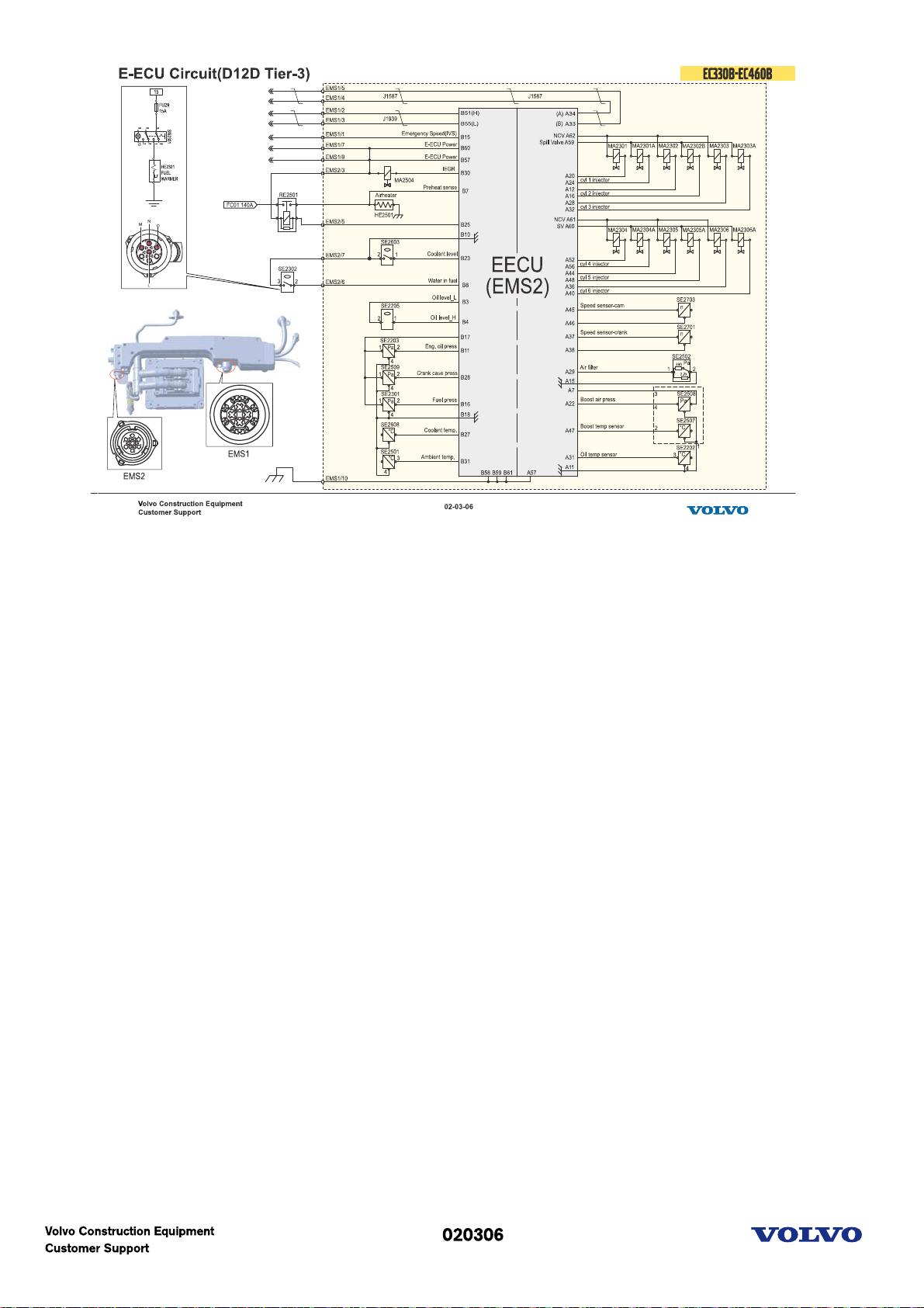
E-ECU circuit (D12D, Tier-3)
Picture text:
 Loading...