


Vx670
Installation Guide
VeriFone Part Number 24003, Revision A

Vx670 Installation Guide
© 2006 VeriFone, Inc.
All rights reserved. No part of the contents of this document may be reproduced or transmitted in any form without the written permission of VeriFone, Inc.
The information contained in this document is subject to change without notice. Although VeriFone has attempted to ensure the accuracy of the contents of this document, this document may include errors or omissions. The examples and sample programs are for illustration only and may not be suited for your purpose. You should verify the applicability of any example or sample program before placing the software into productive use. This document, including without limitation the examples and software programs, is supplied “As-Is.”
VeriFone, the VeriFone logo, Omni, VeriCentre, Verix, and ZonTalk are registered trademarks of VeriFone. Other brand names or trademarks associated with VeriFone’s products and services are trademarks of VeriFone, Inc.
All other brand names and trademarks appearing in this manual are the property of their respective holders. Comments? Please e-mail all comments on this document to your local VeriFone Support Team.
WARNING
Do not dispose of the Vx670 Li-ion smart battery in a fire. Li-ion batteries must be recycled or disposed of properly. Do not dispose of Li-ion batteries in municipal waste sites.
VeriFone, Inc.
2099 Gateway Place, Suite 600
San Jose, CA, 95110 USA
www.verifone.com
VeriFone Part Number 24003, Revision A

CONTENTS
PR EF AC E . . . . . . . . . . . . . . . . . . . . . . . . . . . . . . . . . . . . . . . 5
Audience. . . . . . . . . . . . . . . . . . . . . . . . . . . . . . . . . . . . . . . . . . . . . . . . . . . . . . . . 5
Organization . . . . . . . . . . . . . . . . . . . . . . . . . . . . . . . . . . . . . . . . . . . . . . . . . . . . . 5
Related Documentation . . . . . . . . . . . . . . . . . . . . . . . . . . . . . . . . . . . . . . . . . . . . 5
Conventions and Acronyms . . . . . . . . . . . . . . . . . . . . . . . . . . . . . . . . . . . . . . . . . 6
Document Conventions. . . . . . . . . . . . . . . . . . . . . . . . . . . . . . . . . . . . . . . . . . 6
Acronym Definitions . . . . . . . . . . . . . . . . . . . . . . . . . . . . . . . . . . . . . . . . . . . . 6
CHA P TE R 1 |
|
|
Terminal Overview |
Features and Benefits . . . . . . . . . . . . . . . . . . . . . . . . . . . . . . . . . . . . . . . . . . . . |
10 |
|
Exceptional Ease of Use. . . . . . . . . . . . . . . . . . . . . . . . . . . . . . . . . . . . . . . . |
10 |
|
Performance and Durability . . . . . . . . . . . . . . . . . . . . . . . . . . . . . . . . . . . . . |
10 |
|
True Multi-Application Capability . . . . . . . . . . . . . . . . . . . . . . . . . . . . . . . . . |
11 |
|
Expandable Communication Capabilities . . . . . . . . . . . . . . . . . . . . . . . . . . . |
11 |
|
Wireless Connectivity . . . . . . . . . . . . . . . . . . . . . . . . . . . . . . . . . . . . . . . . . . |
11 |
|
Security . . . . . . . . . . . . . . . . . . . . . . . . . . . . . . . . . . . . . . . . . . . . . . . . . . . . . |
11 |
CHA P TE R 2 |
|
|
Terminal Setup |
Selecting Terminal Location . . . . . . . . . . . . . . . . . . . . . . . . . . . . . . . . . . . . . . . . |
13 |
|
Environmental Factors . . . . . . . . . . . . . . . . . . . . . . . . . . . . . . . . . . . . . . . . . |
13 |
|
Electrical Considerations . . . . . . . . . . . . . . . . . . . . . . . . . . . . . . . . . . . . . . . |
14 |
|
Unpacking the Shipping Carton . . . . . . . . . . . . . . . . . . . . . . . . . . . . . . . . . . . . . |
14 |
|
Examining Terminal Features. . . . . . . . . . . . . . . . . . . . . . . . . . . . . . . . . . . . . . . |
15 |
|
Front Panel . . . . . . . . . . . . . . . . . . . . . . . . . . . . . . . . . . . . . . . . . . . . . . . . . . |
15 |
|
Examining Connection Ports . . . . . . . . . . . . . . . . . . . . . . . . . . . . . . . . . . . . . . . |
16 |
|
Power Adapter Cable . . . . . . . . . . . . . . . . . . . . . . . . . . . . . . . . . . . . . . . . . . |
17 |
|
USB Host Cable . . . . . . . . . . . . . . . . . . . . . . . . . . . . . . . . . . . . . . . . . . . . . . |
17 |
|
Multiport Adapter. . . . . . . . . . . . . . . . . . . . . . . . . . . . . . . . . . . . . . . . . . . . . . |
18 |
|
USB Modem Dongle . . . . . . . . . . . . . . . . . . . . . . . . . . . . . . . . . . . . . . . . . . . |
18 |
|
USB Serial Dongle (RS232 UART). . . . . . . . . . . . . . . . . . . . . . . . . . . . . . . . |
18 |
|
Establishing Telephone Line Connections . . . . . . . . . . . . . . . . . . . . . . . . . . . . . |
19 |
|
Installing the Paper Roll . . . . . . . . . . . . . . . . . . . . . . . . . . . . . . . . . . . . . . . . . . . |
20 |
|
Installing/Replacing MSAM Cards . . . . . . . . . . . . . . . . . . . . . . . . . . . . . . . . . . . |
23 |
|
Installing/Replacing SIM Card |
|
|
(GSM/GPRS Models Only). . . . . . . . . . . . . . . . . . . . . . . . . . . . . . . . . . . . . . . . . |
24 |
|
Using the Smart Battery . . . . . . . . . . . . . . . . . . . . . . . . . . . . . . . . . . . . . . . . . . . |
25 |
|
Smart Battery Features. . . . . . . . . . . . . . . . . . . . . . . . . . . . . . . . . . . . . . . . . |
25 |
|
Battery Behavior (No Power Cord) . . . . . . . . . . . . . . . . . . . . . . . . . . . . . . . . . . . |
26 |
|
Manual Startup . . . . . . . . . . . . . . . . . . . . . . . . . . . . . . . . . . . . . . . . . . . . . . . |
26 |
|
Manual Shutdown . . . . . . . . . . . . . . . . . . . . . . . . . . . . . . . . . . . . . . . . . . . . . |
27 |
|
Installing the Smart Battery . . . . . . . . . . . . . . . . . . . . . . . . . . . . . . . . . . . . . . . . |
27 |
|
Removal . . . . . . . . . . . . . . . . . . . . . . . . . . . . . . . . . . . . . . . . . . . . . . . . . . . . |
27 |
|
Connecting the Terminal Power Pack . . . . . . . . . . . . . . . . . . . . . . . . . . . . . . . . |
28 |
|
Charging the Smart Battery . . . . . . . . . . . . . . . . . . . . . . . . . . . . . . . . . . . . . . . . |
29 |
|
Battery Life . . . . . . . . . . . . . . . . . . . . . . . . . . . . . . . . . . . . . . . . . . . . . . . . . . |
29 |
VX670 INSTALLATION GUIDE |
3 |

CONTENTS
|
Using the Base Station . . . . . . . . . . . . . . . . . . . . . . . . . . . . . . . . . . . . . . . . . . . . |
30 |
|
Standard Base Station . . . . . . . . . . . . . . . . . . . . . . . . . . . . . . . . . . . . . . . . . |
30 |
|
Full-Feature Base Station . . . . . . . . . . . . . . . . . . . . . . . . . . . . . . . . . . . . . . . |
30 |
|
Powering Up the Base Station . . . . . . . . . . . . . . . . . . . . . . . . . . . . . . . . . . . |
31 |
|
Placing the Terminal Onto the Base Station. . . . . . . . . . . . . . . . . . . . . . . . . . . . |
32 |
|
Attaching the USB Dongles to the Base Station. . . . . . . . . . . . . . . . . . . . . . . . . |
32 |
|
Charging the Spare Battery on the Base Station . . . . . . . . . . . . . . . . . . . . . . . . |
33 |
|
Conducting Wireless Transactions . . . . . . . . . . . . . . . . . . . . . . . . . . . . . . . . . . . |
34 |
|
Conducting Smart Card Transactions . . . . . . . . . . . . . . . . . . . . . . . . . . . . . . . . |
34 |
|
Using the Magnetic Card Reader . . . . . . . . . . . . . . . . . . . . . . . . . . . . . . . . . . . . |
35 |
CH AP T ER 3 |
|
|
Specifications |
Power . . . . . . . . . . . . . . . . . . . . . . . . . . . . . . . . . . . . . . . . . . . . . . . . . . . . . . . . . |
37 |
|
DC Power Pack . . . . . . . . . . . . . . . . . . . . . . . . . . . . . . . . . . . . . . . . . . . . . . . . . |
37 |
|
Temperature . . . . . . . . . . . . . . . . . . . . . . . . . . . . . . . . . . . . . . . . . . . . . . . . . . . . |
37 |
|
External Dimensions. . . . . . . . . . . . . . . . . . . . . . . . . . . . . . . . . . . . . . . . . . . . . . |
37 |
CH AP T ER 4 |
|
|
Maintenance |
Cleaning the Terminal . . . . . . . . . . . . . . . . . . . . . . . . . . . . . . . . . . . . . . . . . . . . |
39 |
|
Terminal Contacts . . . . . . . . . . . . . . . . . . . . . . . . . . . . . . . . . . . . . . . . . . . . . . . |
39 |
|
Smart Card Reader . . . . . . . . . . . . . . . . . . . . . . . . . . . . . . . . . . . . . . . . . . . . . . |
39 |
CH AP T ER 5 |
|
|
VeriFone Service |
Returning a Terminal or Smart Battery for Service. . . . . . . . . . . . . . . . . . . . . . . |
41 |
and Support |
Accessories and Documentation . . . . . . . . . . . . . . . . . . . . . . . . . . . . . . . . . . . . |
42 |
|
Power Pack. . . . . . . . . . . . . . . . . . . . . . . . . . . . . . . . . . . . . . . . . . . . . . . . . . |
42 |
|
Thermal Printer Paper. . . . . . . . . . . . . . . . . . . . . . . . . . . . . . . . . . . . . . . . . . |
42 |
|
VeriFone Cleaning Kit . . . . . . . . . . . . . . . . . . . . . . . . . . . . . . . . . . . . . . . . . . |
42 |
|
Spare Battery . . . . . . . . . . . . . . . . . . . . . . . . . . . . . . . . . . . . . . . . . . . . . . . . |
43 |
|
AVX Host Cable . . . . . . . . . . . . . . . . . . . . . . . . . . . . . . . . . . . . . . . . . . . . . . |
43 |
|
Modem Dongle . . . . . . . . . . . . . . . . . . . . . . . . . . . . . . . . . . . . . . . . . . . . . . . |
43 |
|
Serial Dongle . . . . . . . . . . . . . . . . . . . . . . . . . . . . . . . . . . . . . . . . . . . . . . . . |
43 |
|
Telephone Line Cord . . . . . . . . . . . . . . . . . . . . . . . . . . . . . . . . . . . . . . . . . . |
43 |
|
Documentation . . . . . . . . . . . . . . . . . . . . . . . . . . . . . . . . . . . . . . . . . . . . . . . |
43 |
CH AP T ER 6 |
|
|
Troubleshooting |
Terminal Does Not Start . . . . . . . . . . . . . . . . . . . . . . . . . . . . . . . . . . . . . . . . . . . |
45 |
Guidelines |
Terminal Display Does not Show Correct/Readable Info . . . . . . . . . . . . . . . . . . |
45 |
|
Smart Battery Will Not Charge . . . . . . . . . . . . . . . . . . . . . . . . . . . . . . . . . . . . . . |
46 |
|
Spare Battery in Base Station Will Not Charge . . . . . . . . . . . . . . . . . . . . . . . . . |
46 |
|
Blank Display . . . . . . . . . . . . . . . . . . . . . . . . . . . . . . . . . . . . . . . . . . . . . . . . . . . |
46 |
|
Terminal Does Not Dial Out . . . . . . . . . . . . . . . . . . . . . . . . . . . . . . . . . . . . . . . . |
46 |
|
Printer Does Not Print. . . . . . . . . . . . . . . . . . . . . . . . . . . . . . . . . . . . . . . . . . . . . |
47 |
|
Printer Paper Jam. . . . . . . . . . . . . . . . . . . . . . . . . . . . . . . . . . . . . . . . . . . . . . . . |
47 |
|
Keypad Does Not Respond . . . . . . . . . . . . . . . . . . . . . . . . . . . . . . . . . . . . . . . . |
47 |
|
Transactions Fail To Process . . . . . . . . . . . . . . . . . . . . . . . . . . . . . . . . . . . . . . . |
47 |
|
IN DE X . . . . . . . . . . . . . . . . . . . . . . . . . . . . . . . . . . . . . . . . .49 |
|
4 VX670 INSTALLATION GUIDE

PREFACE
This guide is your primary source of information for setting up and installing the Vx670 terminal.
Audience This guide is useful for anyone installing and configuring a Vx670 terminal. Basic descriptions of the terminal features are also provided.
Organization
Related
Documentation
This guide is organized as follows:
Chapter 1, Terminal Overview. Provides an overview of the Vx670 terminal.
Chapter 2, Terminal Setup. Explains how to set up and install the Vx670 terminal. It tells you how to select a location, establish power and telephone line connections, and how to configure optional peripheral devices.
Chapter 3, Specifications. Discusses power requirements and dimensions of the Vx670 terminal.
Chapter 4, Maintenance. Explains how to maintain your Vx670 terminal.
Chapter 5, VeriFone Service and Support. Provides information on contacting your local VeriFone representative or service provider, and information on how to order accessories or documentation from VeriFone.
Chapter 6, Troubleshooting Guidelines. Provides troubleshooting guidelines, should you encounter a problem in terminal installation and configuration.
To learn more about the Vx670 terminal, refer to the following set of documents:
Vx670 Certifications and Regulations Sheet |
VPN 24000 |
|
Vx670 |
Quick Installation Guide |
VPN 24001 |
Vx670 |
Reference Manual |
VPN 24004 |
Vx670 |
Base and Dongle Quick Installation Guide |
VPN 24005 |
Vx670 |
Standard Base Quick Installation Guide |
VPN 24006 |
Verix V Operating System Programmer’s Manual |
VPN 23230 |
|
Verix V Tools Programmer’s Manual |
VPN 23231 |
|
VX670 INSTALLATION GUIDE |
5 |

PREFACE
Conventions and Acronyms
Conventions and
Acronyms
Document
Conventions
This section describes the conventions and acronyms used in this guide.
Various conventions are used to help you quickly identify special formatting. Table 1 describes these conventions and provides examples of their use.
Table 1 Document Conventions
Convention |
Meaning |
Example |
|
|
|
Blue |
Text in blue indicates terms |
See Conventions and Acronyms. |
|
that are cross referenced. |
|
Italics |
Italic typeface indicates |
You must install a roll of thermal- |
|
book titles or emphasis. |
sensitive paper in the printer. |
Courier |
The courier type face is |
http://www.verifone.com |
|
used while specifying |
|
|
onscreen text, such as text |
|
|
that you would enter at a |
|
|
command prompt, or to |
|
|
provide an URL. |
|
|
|
|
The pencil icon is used to NOTE highlight important
information.
The caution symbol CAUTION indicates possible hardware
or software failure, or loss of data.
RS-232-type devices do not work with the PINpad port.
The terminal is not waterproof or dustproof, and is intended for indoor use only.
WARNING |
The lightning symbol is |
Due to risk of shock do not use the |
||
used as a warning when |
terminal near water. |
|||
|
|
|
bodily injury might occur. |
|
|
|
|
|
|
|
|
|
|
|
Acronym Definitions Various acronyms are used in place of the full definition. Table 2 presents acronyms and their definitions.
Table 2 |
Acronym Definitions |
Acronym |
Definitions |
|
|
AC |
Alternating Current |
ATM |
Automated Teller Machine |
CDMA |
Code Division Multiple Access |
CR |
Check Reader |
EMV |
Europay MasterCard and VISA |
GPRS |
General Packet Radio Service |
GSM |
Global System for Mobile Communication |
ITP |
Internal Thermal Printer |
|
|
6 VX670 INSTALLATION GUIDE

PREFACE
Conventions and Acronyms
Table 2 |
Acronym Definitions (continued) |
Acronym |
Definitions |
|
|
LCD |
Liquid Crystal Display |
LED |
Light Emitting Diode |
MRA |
Merchandise Return Authorization |
MSAM |
Micromodule-Size Security Access Module |
PED |
PIN-Entry Devices |
PIN |
Personal Identification Number |
RJ45 |
Registered Jack 45 |
RS-232 |
Recommended Standard 232 |
SAM |
Security Access Module |
SIM |
Subscriber Identity Module |
UART |
Universal Asynchronous Transmitter/Receiver |
USB |
Universal Serial Bus |
VPN |
VeriFone Part Number |
Wi-Fi |
Wireless Fidelity |
|
|
VX670 INSTALLATION GUIDE |
7 |

PREFACE
Conventions and Acronyms
8 VX670 INSTALLATION GUIDE
CHAPTER 1
Terminal Overview
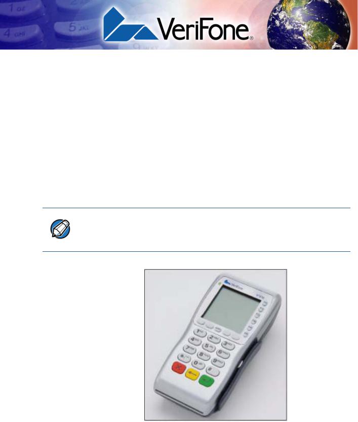
This chapter provides a brief description of the Vx670 terminal. The Vx670 terminal represents a revolution for e-payment. The Vx670 device uses a bold ergonomic design that is sleek and stylish, offering countertop power and 32-bit performance in an integrated terminal that can be handed to the consumer for input, making it ideal for pay-at-table usage.
The Vx670 terminal is a portable, battery-powered device that uses wireless technologies, including Wi-Fi with 802.11g technology and GSM/GPRS. It also features a 128-by-128 pixel display and a speedy thermal printer.
NOTE VeriFone ships variants of the Vx670 terminal for different markets. Your terminal may have a different configuration. The following devices may or may not be present: a smart card reader, zero or three MSAM cardholders, and/or a SIM cardholder.
Figure 1 The Vx670 terminal.
VX670 INSTALLATION GUIDE |
9 |

TERMINAL OVERVIEW
Features and Benefits
Features at a glance
•32-bit ARM9 processor delivers power and usability in a convenient
“hand-over” design.
•Multi-application operating environment.
•32-bit processing and multi-tasking capabilities.
•USB support for VeriFone peripheral devices.
•Backward compatibility with VeriFone solutions reduces development costs.
•Drop resistant design minimizes breakage.
•Securely supports and runs payment and value-added applications.
•Offers unsurpassed performance on
EMV smart card transactions.
•Security architecture meets specifications for PCI-PED and sophisticated file authentication.
•Max UI design provides large display on small footprint.
•Designed to meet the needs of
TablePAY, DeliveryPAY, and CarsidePAY markets.
•Spill resistant design forces liquid down and off the front of the terminal.
Features and
Benefits
Vx670 terminals provide the right combination of features and functions. This includes a triple-track magnetic-stripe card reader, smart card reader, integrated PINpad, and a quiet yet fast internal thermal printer (ITP).
Exceptional Ease of |
• Lightweight (less than 1 pound), tapered design is compact and stylish and the |
Use |
ergonomic balance allows for convenient terminal hand-off to the consumer |
|
for PIN entry or other input. |
|
• 128-by-128 pixel display with anti-glare, adjustable contrast, dimming |
|
capability, intuitive ATM-style interface, and oversized menu prompts simplify |
|
training and reduce calls to the helpdesk. |
|
• Large, well-placed, blue backlit keys provide improved tactile response to |
|
simplify usage and minimize finger slips. |
|
• Integrated high-speed thermal printer prints quickly and silently, and simplified |
|
paper loading virtually eliminates paper jams. |
|
• Triple-track, high-coercivity card reader handles most magnetic stripe cards. |
|
• Optional Base Station with battery charger supports connectivity to a UART |
|
module or a 14,400 bps modem via USB dongles. |
|
• Accepts all types of payments – including debit. |
Performance and |
• 32-bit processing and multi-tasking capabilities make short work of payment, |
Durability |
payment-related, and value-added applications. |
|
• Exceptional graphics-handling capabilities of display and printer quickly render |
|
logos, graphical fonts, and character-based languages. |
|
• VeriCentre Appliance Management Suite employs advanced file compression |
|
to streamline simultaneous downloads of application software to hundreds of |
|
terminals. |
|
• Rounded corners and drop-resistant design minimizes breakage. |
10 VX670 INSTALLATION GUIDE
TERMINAL OVERVIEW
Features and Benefits
•
•
•
•
•
True Multi- •
Application
Capability •
Sealed MSR blade locks out moisture for excellent spill resistance.
Innovative design resists spills by forcing liquid down and off the front of the terminal
Integrated PINpad offers added convenience to handle PIN-based applications.
Uncompromising reliability from VeriFone, the worldwide leader in e-payment.
Complies with RoHS (Restriction of Hazardous Substances) directive of the European Union.
6 MB of memory and the Verix V OS dynamic memory allocation support two or three typical-sized applications on a single terminal.
Primary smart card reader and MSAMs safeguard sensitive financial data and support multiple smart card schemes.
• Vx670 series of terminals and SoftPay EMV software have received EMV
|
|
Level 1 and Level 2 Type approval for smart card solutions. Verix EMV Library |
|
|
provides efficient development of other EMV-compliant applications. |
|
• VeriShield security architecture meets published specifications for PCI-PED |
|
|
|
and provides sophisticated file authentication to prevent execution of |
|
|
unauthorized software on Vx670 terminals. |
Expandable |
• |
USB Host Port |
Communication |
• |
USB Device Port for application debugging |
Capabilities |
• RS-232, Serial Port |
|
|
||
|
• |
14,400 bps Modem |
|
• Universal Asynchronous Receiver/Transmitter (UART) port |
|
Wireless |
• |
Customers are not tied to a fixed location with the Vx670 wireless terminals – |
Connectivity |
|
the point of payment can be almost anywhere. |
• “Always-on” wireless connection uses the latest wireless technologies, including GSM/GPRS and Wi-Fi with 802.11g technology for faster transmission and enhanced compatibility with access points and routers.
Security • WPA-PSK (pre-shared keys) protects Wi-Fi transactions.
•Other security features include tamper-resistant construction, adoption of SSL protocols, and VeriShield file authentication.
VX670 INSTALLATION GUIDE |
11 |

TERMINAL OVERVIEW
Features and Benefits
12 VX670 INSTALLATION GUIDE

CHAPTER 2
Terminal Setup
This chapter describes the terminal setup procedure. You will learn about:
•Selecting Terminal Location.
•Unpacking the Shipping Carton.
•Examining Terminal Features.
•Examining Connection Ports.
•Establishing Telephone Line Connections.
•Installing the Paper Roll.
•Installing/Replacing MSAM Cards.
•Installing/Replacing SIM Card (GSM/GPRS Models Only).
•Using the Smart Battery.
•Battery Behavior (No Power Cord).
•Installing the Smart Battery.
•Charging the Smart Battery.
•Connecting the Terminal Power Pack.
•Using the Base Station.
•Placing the Terminal Onto the Base Station.
•Attaching the USB Dongles to the Base Station.
•Charging the Spare Battery on the Base Station.
•Conducting Wireless Transactions.
•Conducting Smart Card Transactions.
•Using the Magnetic Card Reader.
Selecting Use the following guidelines when selecting a location for your Vx670 terminal.
Terminal
Location
Environmental |
• |
The Vx670 is a portable terminal. Select a flat support surface, such as a |
|
Factors |
|
countertop or table, to keep the terminal safe in between uses. |
|
|
• |
Do not use the terminal where there is high heat, dust, humidity, moisture, or |
|
|
|
caustic chemicals or oils. |
|
|
|
VX670 INSTALLATION GUIDE |
13 |

TERMINAL SETUP
Unpacking the Shipping Carton
•Keep the terminal away from direct sunlight and anything that radiates heat, such as a stove or motor.
•Do not use the terminal outdoors.
CAUTION The terminal is not waterproof or dustproof, and is intended for indoor use only. Any damage to the unit from exposure to rain or dust may void any warranty.
Electrical •
Considerations •
•
Avoid using this product during electrical storms.
Avoid locations near electrical appliances or other devices that cause excessive voltage fluctuations or emit electrical noise (for example, air conditioners, electric motors, neon signs, high-frequency or magnetic security devices, or computer equipment).
Do not use the terminal near water or in moist conditions.
Unpacking the
Shipping Carton
To unpack the Shipping Carton
Open the shipping carton and carefully inspect its contents for possible tampering or shipping damage. The Vx670 is a secure product and any tampering may cause the terminal to cease to function properly.
1Remove and inspect the following items:
•Terminal
•Power pack
•Telephone line cord
•Power cord
•Battery pack
•Paper roll
2Remove all plastic wrapping from the terminal and other components.
3Remove the clear protective film from the LCD screen.
CAUTION Do not use a terminal that has been damaged or tampered with. The Vx670 terminal comes equipped with tamper-evident labels. If a label or component appears damaged, please notify the shipping company and your VeriFone representative or service provider immediately.
4Save the shipping carton and packing material for future repacking or moving the terminal.
14 VX670 INSTALLATION GUIDE
TERMINAL SETUP
Examining Terminal Features
Examining
Terminal
Features
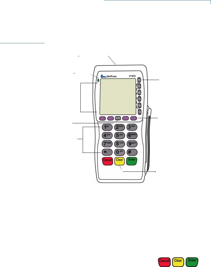
Before you continue the installation process, notice the features of the Vx670 terminal (see Figure 2).
INTERNAL THERMAL 
PRINTER (AT THE BACK)
INDICATOR LED 
ATM-STYLE FUNCTION
KEYS
TERMINAL DISPLAY |
|
|
|
MAGNETIC CARD |
|
|
|
READER |
|
|
||||
|
|
|
|
|
PROGRAMMABLE
FUNCTION KEYS
ALPHA KEY
TELEPHONE-STYLE
KEYPAD
CANCEL KEY |
|
|
|
|
|
ENTER KEY |
|
|
|
|
|
||
|
|
|
CLEAR KEY |
|||
|
||||||
|
|
|
|
|
SMART CARD READER |
|
|
|
|
|
|
||
|
|
|
|
|
||
Figure 2 Vx670 Terminal Features (Front Panel)
Front Panel The front panel includes the following features:
•A terminal display, backlit LCD screen.
•Five types of keys:
a A 12-key, telephone-style keypad (keypads may vary in style).
b Six ATM-style function keys, labeled F0 to F5, to the right of the LCD screen.
c Four programmable function keys above the keypad. d Three color-coded function keys below the
keypad (icons at right; from left to right: CANCEL,
CLEAR, ENTER).
e An ALPHA key centered at the top of the keypad.
VX670 INSTALLATION GUIDE |
15 |
TERMINAL SETUP
Examining Connection Ports
•A magnetic card reader, built into the right side. Swipe the card using the proper direction, with the magnetic stripe down and facing inward, toward the keypad.
•A green indicator LED indicates power is ON.
•An internal thermal printer at the back of the terminal.
•A smart card reader, built into the front of the terminal. For directions on how to use a smart card, see Conducting Smart Card Transactions.
•A SAM (security access module) compartment, built into the bottom of the terminal. The Vx670 terminal contains MSAM cardholders to support multiple stored-value card programs or other merchant card requirements.
NOTE VeriFone ships variants of the Vx670 terminal for different markets. Your terminal may have a different configuration. The following devices may or may not be present: a smart card reader, or zero or three MSAM cardholders. However, the basic processes described in this guide remain the same, regardless of terminal configuration.
Examining
Connection
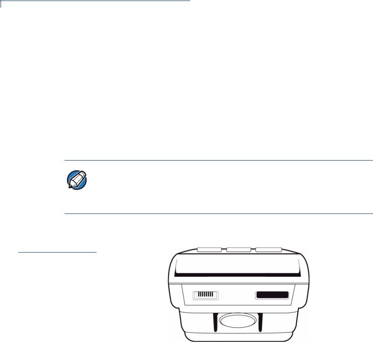
Ports
The Vx670 terminal has one primary port that supports different peripherals through the use of various cables.
Figure 3 The Vx670 Primary Port (Bottom View)
16 VX670 INSTALLATION GUIDE
 Loading...