


New York State Department of Health
(NYS DOH)
Office of Health Insurance Programs
(OHIP)
eMedNY POS Start Guide
VERIFONE Vx570 and Vx610
TERMINALS
Publish Date:01/01/2013
Version 1.1
May 01, 2011
Version 1.0

POS Start Guide
Table of Contents |
|
INTRODUCTION TO THE MEVS VERIFONE TERMINAL..................................................... |
2 |
VERIFONE Vx570 TERMINAL ................................................................................................... |
3 |
Vx570 Terminal Description– Front........................................................................................... |
3 |
Vx570 Terminal – Back.............................................................................................................. |
5 |
Terminal Power Pack and Cables ............................................................................................... |
5 |
Vx570 Installation Instructions................................................................................................... |
6 |
Quick Start.......................................................................................................................................... |
6 |
Connecting the Telephone Line.......................................................................................................... |
7 |
Connecting the Terminal Power Pack ................................................................................................ |
7 |
VERIFONE Vx570 FUNCTIONS ................................................................................................. |
8 |
Initial Screen ............................................................................................................................... |
8 |
Instructions to Reset Day/Date/Time.......................................................................................... |
8 |
Instructions for Setup Menu (P1 Key)...................................................................................... |
11 |
Instructions for Provider Menu (P2 key) .................................................................................. |
14 |
VERIFONE VX610 TERMINAL .................................................................................................... |
16 |
Vx610 Terminal Description – Front........................................................................................ |
16 |
Vx610 Installation Instructions................................................................................................. |
17 |
Quick Start........................................................................................................................................ |
18 |
Connecting/Removing the Battery ................................................................................................... |
18 |
Connecting the Antenna ................................................................................................................... |
19 |
Connecting the Telephone Line (If only being used indoors) .......................................................... |
20 |
Connecting the Terminal Car Charger and/or Power Pack .............................................................. |
20 |
VERIFONE Vx610 FUNCTIONS ............................................................................................... |
21 |
Initial Screen ............................................................................................................................. |
21 |
Instructions to Reset Day/Date/Time........................................................................................ |
22 |
Instructions for Setup Menu (P1 Key)...................................................................................... |
25 |
Instructions for Provider Menu (P2 key) .................................................................................. |
27 |
How to enter a National Provider Identifier (NPI) or MMIS Number ..................................... |
27 |
COMMON FUNCTIONS FOR ALL TERMINAL TYPES ........................................................ |
29 |
Review Function ....................................................................................................................... |
29 |
Inserting Thermal Paper into the Internal Thermal Printer....................................................... |
29 |
Ordering Thermal Paper for the Internal Thermal Printer........................................................ |
30 |
Card Swipe................................................................................................................................ |
30 |
Common MEVS Terminal Messages ....................................................................................... |
31 |
Jan 2013 |
1 |
Introduction |

POS Start Guide
INTRODUCTION TO THE MEVS VERIFONE TERMINAL
The VeriFone terminal is designed to provide an accurate and timely verification of a member’s eligibility for Medicaid services.
Specific features and conveniences, such as a large LCD screen, ATM style buttons and a built in printer, make the verification process easy to learn and use with a minimum of training time.
The eMedNY system currently supports 2 different terminal types. Each terminal model is identified just above the LCD screen of your terminal. They are:
•VeriFone Vx 570
•VeriFone Vx 610
It is important to know which terminal is operating on the eMedNY system. Any software updates to the terminal will be communicated via New York State Medicaid Updates, eMedNY LISTSERV® and www.emedny.org/POS.
Jan 2013 |
2 |
Introduction |

POS Start Guide
VERIFONE Vx570 TERMINAL
The VeriFone Vx570 terminal uses a basic analog telephone outlet to connect with Medicaid Eligibility Verification System (MEVS). Please review www.eMedny.org/pos for future alternate connectivity updates.
|
Vx570 Terminal Description– Front |
|
A. |
INTERNAL THERMAL PRINTER |
A dot matrix printer in which heat is applied to the pins |
|
|
of the matrix to form dots on heat-sensitive paper. |
B. |
INDICATOR LED |
Power and Paper Indicator. |
|
|
NOTE: A blinking light indicates to check paper supply |
|
|
or paper is not inserted properly. |
C.PAPER COVER RELEASE
D.F4 ATM-STYLE FUNCTION KEY
E.LCD SCREEN
F.MAGNETIC CARD READER
Opens the printer paper compartment.
Starts a verification transaction through entry of the access number or Medicaid Number.
The verification response and system messages will be displayed in this area.
Slot that reads the magnetic stripe on the back of the card. This allows for quicker entry of verification transactions.
G. ALPHA KEY |
Converts numeric digits to alphabetic letters. |
Jan 2013 |
3 |
VeriFone Vx570 |

|
|
POS Start Guide |
|
|
|
|
|
H. |
PAPER ADVANCE KEY |
Press the 3 Key from the initial screen to advance the |
|
|
|
paper one line at a time. |
|
I. |
TELEPHONE STYLE KEYPAD |
Area where user enters data needed for the Medicaid |
|
|
|
verification. |
|
J. |
GREEN ENTER KEY |
Inputs new data into the system. |
|
K. |
YELLOW BACKSPACE KEY |
Erases the last numeric digit or alphabetic letter entered. |
|
L. |
RED CANCEL KEY |
Erases all previously entered data and returns to the |
|
|
|
ready mode. |
|
M. |
REPRINT KEY |
Press the 0 (Zero) key from the initial screen, prints a |
|
|
|
duplicate copy of the verification message. |
|
N. |
P1 SETUP KEY |
Allows modification of the Terminal Settings. Refer to |
|
|
|
the section on Instructions for Setup Menu (P1 Key) of |
|
|
|
this manual. |
|
O. |
P2 PROVIDER KEY |
Allows for add, update, delete, and review of multiple |
|
|
|
provider Ids. Refer to the section on Instructions for |
|
|
|
Provider Menu (P2 key) of this manual. |
|
P. |
P3 SCROLL BACK KEY |
Facilitates scrolling to the previous line, if applicable. |
|
Q. |
P4 SCROLL FORWARD/REVIEW |
Facilitates scrolling to the next line, if applicable. Also is |
|
|
KEY |
used to review the previous transaction. |
|
Jan 2013 |
4 |
VeriFone Vx570 |
POS Start Guide
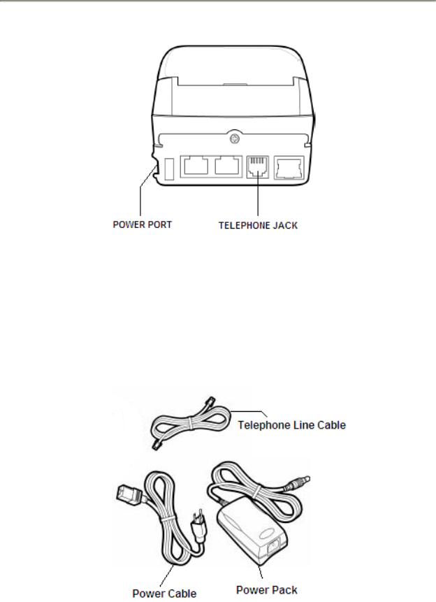
Vx570 Terminal – Back
Terminal Power Pack and Cables
Each Vx570 comes with a Telephone Line Cable, Power Cable and Power Pack. The Telephone line cable connects to your terminal and also connects to your RJ11-type modular telephone wall jack. The Power Cable is a standard computer power cable and plugs into a 120-volt AC outlet (indoor only).The Power Pack connects the terminal to the power cable.
Jan 2013 |
5 |
VeriFone Vx570 |

POS Start Guide
Vx570 Installation Instructions
These instructions will assist with the setup of the VeriFone Vx570 terminal. Select a location that has access to a power outlet and a telephone line for your terminal.
Note: Digital Telephone lines are not compatible with any Medicaid POS terminals. Please consult with your Telecommunications Department, Office Manager or Telephone Company if you have any questions regarding your telephone service.
Quick Start
The Quick Start is an easy way to setup up the VeriFone Vx570 terminal.
1.Select a location that has access to a power outlet and a telephone line for your terminal. Open the box and unpack the terminal.
2.Connect the telephone line cable into the telephone jack labeled with an image of a telephone in the back of the terminal. Connect the other end into the wall jack.
3.Connect the power connector into the power port on the side of the terminal, and the power cable into the power pack. Plug the three-prong power cable into the power outlet.
4.After the device has gone through its start-up routine, the day, date, and time is displayed on the top line of the terminal.
5.Enter your National Provider Identifier(s) (NPI) or MMIS Identification Number(s) (A typical providers only). Refer to the section on Instructions for Provider Menu (P2 key) of this manual.
6.If you are required to dial a number to get an outside line (e.g. ‘9’), Refer to the section on Instructions for Setup Menu (P1 key) of this manual.
7.Press the F4 key or swipe the Medicaid ID card in the Magnetic Card Reader to begin processing transactions to eMedNY.
Jan 2013 |
6 |
VeriFone Vx570 |
POS Start Guide
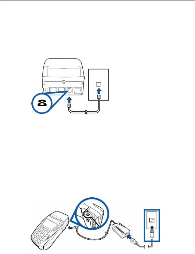
Connecting the Telephone Line
1.Connect one end of the telephone line cable to the telephone jack labeled with an image of a telephone in the back of the terminal.
2.Connect the other end of the telephone line cable to a RJ11-type modular telephone wall jack (See illustration below). If you do not have a telephone wall jack, obtain an adapter from your local telephone company.
Connecting the Terminal Power Pack
1.Connect the power connector into the power port located on the side of the terminal.
2.Connect the power cable into the power pack.
3.Plug the three-prong AC power cable into an indoor 120-volt AC outlet as shown in the illustration below.
WARNING: Do not plug the power pack into an outdoor outlet or operate the terminal outdoors.
Jan 2013 |
7 |
VeriFone Vx570 |

POS Start Guide
VERIFONE Vx570 FUNCTIONS
Initial Screen
When the VeriFone Vx570 terminal is not actively being used, the device normally shows its “initial screen” (see below). To get to this screen in most circumstances, press the RED CANCEL key.
Initial screen example:
FRI 9/5 9-13A
EMEDNY
SWIPE CARD OR
PRESS F4 TO BEGIN
Vxxxx
The “xxxx” in “Vxxxx” on the bottom line is the software version the terminal is using. This number may be needed when calling provider services for assistance. Please review www.emeny.org/pos for any software updates to the terminals.
Instructions to Reset Day/Date/Time
To set or reset the day, date, and time follow the Display/Action tables.
DISPLAY |
|
ACTION |
The Initial Screen is displayed. |
Press the F2 & F4 keys at the same time. |
|
|
|
|
SYSTEM MODE ENTRY PASSWORD |
Enter “Z66831” (1-alpha-alpha 66831) and |
|
|
|
press the GREEN ENTER key. |
|
|
|
IF THE SCREEN READS: |
||
SYS MODE MENU 1 |
|
SYS MODE MENU 1 |
CONTRAST F2 |
|
EDIT PARAMETERS F2 |
CLOCK F3 |
|
DOWNLOAD F3 |
RESTART F4 |
|
RESTART F4 |
|
|
|
The device is an Early Model Vx570. |
|
The device is a Late Model Vx570. |
Please continue with GRID #1: |
|
Please continue with GRID #2: |
|
|
|
Jan 2013 |
8 |
VeriFone Functions |
|
|
Vx570 |

POS Start Guide
GRID # 1:
DISPLAY |
|
ACTION |
|
|
|
||
SYS MODE MENU 1 |
Press the F3 key for CLOCK. |
||
|
|
|
|
SYS MODE CLOCK |
|
|
|
YEAR : |
YYYY |
Enter the current date as “YYYYMMDD“. |
|
MONTH : |
MM |
||
|
|||
DAY : |
DD |
|
|
|
|
|
|
|
|
Press the Provider (P2) key: |
|
SYS MODE CLOCK |
|
Enter the current time as “HH:MM” |
|
HOUR : |
HH |
Enter HH in 24-Hour clock format. |
|
MINUTE : MM |
(i.e.: 1:00pm - Hour: 13 Minute: 00) |
||
|
|||
|
|
Press the GREEN ENTER key to Save & Exit |
|
SYS MODE MENU 1 |
Press the F4 key to restart the device. |
||
|
|
|
|
Device will re-start and Initial Screen should display the correct Day, Date, and Time.
GRID # 2:
DISPLAY |
|
ACTION |
|
|
|
|
|
SYS MODE MENU 1 |
|
Press the Provider (P2) key |
|
|
|
|
|
SYS MODE MENU 2 |
|
|
|
MEMORY FUNCATIONS |
F2 |
Press the F4 key for CLOCK |
|
TERMINAL INFO |
F3 |
||
|
|||
CLOCK |
F4 |
|
|
|
|
|
Jan 2013 |
9 |
VeriFone Functions |
|
|
Vx570 |
 Loading...