

Page 1
10A / ACHTERGRONDVERLICHTING
ÉCLAIRAGE
10A / RETROILUMINACIÓN
10A / HINTERGRUNDBELEUCHTUNG
Z PODŚWIETLENIEM
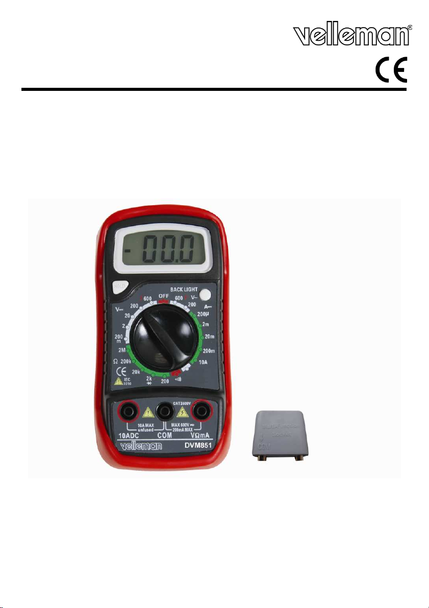
DVM851
3 1/2 DMM - 10A / BACKLIGHT
3 1/2-DIGIT DMM MULTIMÈTRE NUMÉRIQUE LCD 3 1/2 - 10A / RÉTROMULTÍMETRO 3 ½ DÍGITOS 3 ½-STELLIGES MULTIMETER CYFROWY MULTIMIERNIK 3 1/2 - 10A –
USER MANUAL 3
GEBRUIKERSHANDLEIDING 9
NOTICE D’EMPLOI 16
MANUAL DEL USUARIO 23
BEDIENUNGSANLEITUNG 29
INSTRUKCJA UŻYTKOWNIKA 36
Page 2
DVM851
01.08.2012 ©Velleman nv
2
Page 3
DVM851
is symbol on the device or the package indicates that disposal of the device after its
Do not dispose of the unit (or batteries) as unsorted municipal waste; it should be taken to a
his device should be returned to your distributor or to a local recycling service.
bringing this device into
service. If the device was damaged in transit, don't install or use it and contact your dealer.
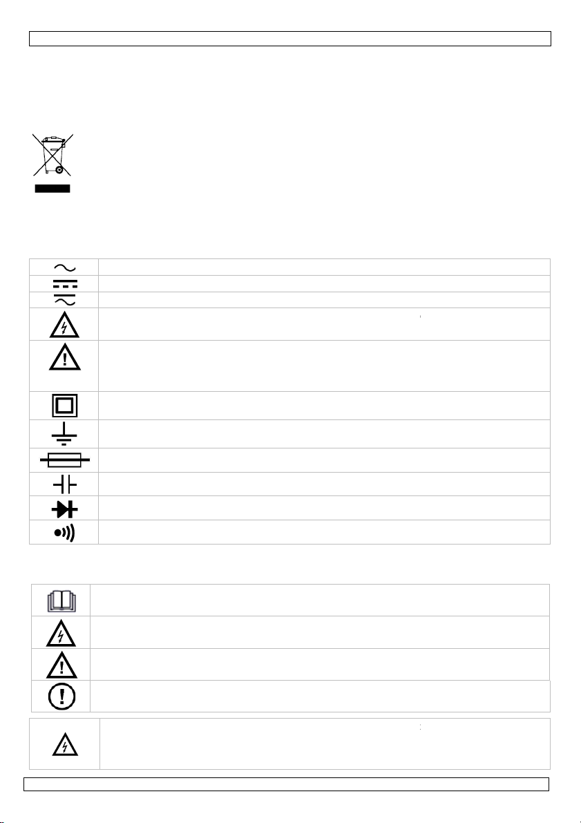
AC (Alternating Current)
DC (Direct Current)
Both AC and DC
Risk of Electric shock.
A potentially hazardous vo
ltage is possible.
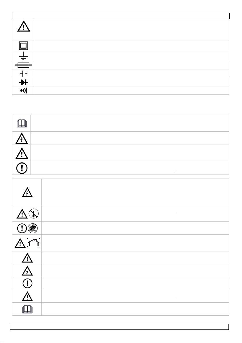
Caution: risk of danger,
refer to the user manual for safety information.
: a hazardous condition or action that may result in injury or death
: condition or action that may result in damage to the meter or equipment und
Double insulation (class II
-
protection)
Earth
Fuse
Capacitor
Diode
Continuity
on the last pages of this manual.
t reading the instructions and manual can lead to damage, injury or death.
action that may result in damage, injury or death
WARNING:
To avoid electrical shock
always
disconnect the test leads prior to openi
To prevent fire hazards, only use fuses with the same ratings as specified in
ng
User manual
1. Introduction
To all residents of the European Union
Important environmental information about this product
Th
lifecycle could harm the environment.
specialized company for recycling.
T
Respect the local environmental rules.
If in doubt, contact your local waste disposal authorities.
Thank you for choosing Velleman! Please read the manual thoroughly before
2. Used symbols
Warning
Caution
test
3. General Guidelines
Refer to the Velleman® Service and Quality Warranty
This symbol indicates: Read instructions
No
This symbol indicates: Danger
A hazardous condition or action that may result in injury or death
This symbol indicates: Risk of danger/damage
Risk of a hazardous condition or
the housing.
this manual.
Remark: refer to the warning on the battery compartment
01.08.2012
3
er
information
©Velleman nv
Page 4
DVM851
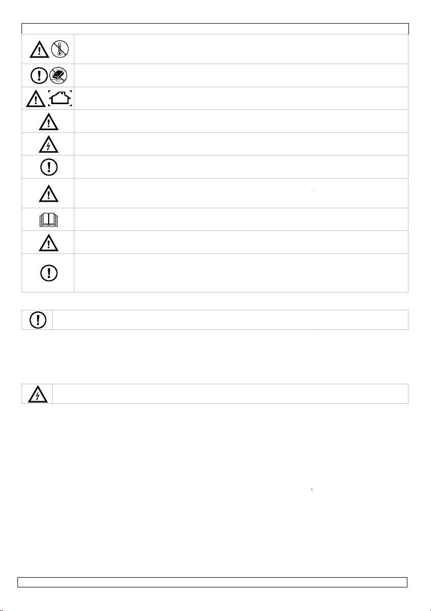
Avoid cold, heat and large temperature fluctuations. When the unit is moved from a cold t
a warm location, leave it switched off until it has reached room temperature. This to avoid
. Avoid brute force when operating.
only. Keep this device away from rain, moisture,
§8
l when measuring live circuits.
This is an installation category CAT II measuring instrument. Never
Overvoltage/installation
Read this addendum and the manual thoroughly. Familiarise yourself with the functions of
ty reasons. Damage caused by user
Only use the device for its intended purpose. Using the device in an unauthorized way will
void the warranty. Damage caused by disregard of certain guidelines
covered by the warranty and the dealer will not accept responsibility for any ensuing
the jacks
§11 battery and fuse replacement
mild detergent for cleaning
Be very careful when measuring live circuits.
Never exceed the limit value for protection. This limit value is listed separately in the specifications for
Do not touch unused terminals when the meter is linked to a circuit which is being tested.
Never use the meter with category II installations when measuring voltages that might exceed the
range selector at its highest position if the intensity of the charge to be measured is unknown
Disconnect the test leads from the tested circuit before rotating the range selector in order to change
n a TV set or switching power circuits, always remember that the
Always be careful when working with voltages above 60Vdc or 30Vac rms. Keep your fingers behind the
Make sure all capacitors in
o
use this
the jacks
condensation and measuring errors.
Protect this device from shocks and abuse
Pollution degree 2-device. For indoor use
splashing and dripping liquids. Not for industrial use. Refer to
Keep the device away from children and unauthorised users.
Risk of electric shock during operation. Be very carefu
There are no user-serviceable parts inside the device.
Refer to an authorized dealer for service and/or spare parts.
equipment in a CAT III or CAT IV environment. Refer to §7
category.
the device before actually using it.
All modifications of the device are forbidden for safe
modifications to the device is not covered by the warranty.
defects or problems.
4. Maintenance
There are no user-serviceable parts inside the device.
Refer to an authorized dealer for service and/or spare parts.
•
Before performing any maintenance activities, disconnect the test leads from
•
For instructions on replacing battery or fuse, refer to
• Do not apply abrasives or solvents to the meter. Use a damp cloth and
purposes.
5. During use
Pollution degree.
in this manual is not
.
.
Risk of electric shock during operation.
•
each range of measurement.
•
•
safety margin of 600V above earth ground.
•
Set the
beforehand.
•
functions.
•
When carrying out measurements o
meter may be damaged by any high amplitude voltage pulses at test points.
•
probe barriers at all times during measurement.
•
Never perform resistance, diode or continuity measurements on live circuits.
the circuit are depleted.
01.08.2012
4
©Velleman nv
Page 5
DVM851
easuring DC and AC
voltages, DC current and resistance. It also offers the possibility of executing continuity tests and of
When this button is pushed, the backlight will illuminate your display for approximately 5 seconds.
This switch is used to select functions and desired ranges as well as to turn the meter on/off.
Insert the red test lead in this connector in order to measure a max. current of 10A.
Insert the red (positive) test lead in this connector to measure voltage, resistance and current
nd severity of transient overvoltage that might occur at the
lived bursts of energy induced in a system, e.g. caused by lightning
A CAT I
-rated meter is suitable for measurements on protected electronic circuits that are not
directly connected to mains power, e.g. electronics circuits, control signals…
A CAT II
-
rated meter is suitable for measurements in CAT
I-
environments and mono
appliances that are connected to the mains by means of a plug and circuits in a normal
domestic environment, provided that the circuit is at least 10m apart from a CAT III
environment. E.g. household appliances, portable too
A CAT III
-
rated meter is suitable for measurements in CAT
I- and CAT II
phased appliances which are at least 10m apart
on distribution level equipment
A CAT IV
-
rated meter is suitable for measuring in CAT I
-
, CAT II
- and CAT III
quipment for which the supply cables run outdoors (either
1 installation category CAT II 600V. This implies
se apply that are related to voltages and voltage peaks which can occur
f pollution environments, for which different protective measures
are necessary to ensure safety. Harsher environments require more protection, and the protection
against the pollution which is to be found in a certain environment depends mainly on the ins
the enclosure properties. The pollution degree rating of the DVM indicates in which environment the
Pollution degree 1
No pollution or only dry, nonconductive pollution occurs. The pollution has no
nd in hermetically sealed enclosures)
Pollution degree 2
Only nonconductive pollution occurs. Occasionally, temporary conductivity caused by
-phase
-
environments, as well
-
environments as
6.
General description
The DVM851 is a battery-operated, hand-held 3 ½ digital multi-meter for m
testing diodes and transistors. The back light is optional.
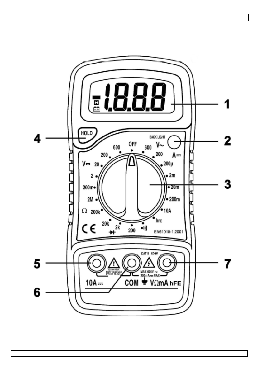
Refer to the illustration on page 2 of this manual:
Display
3 ½ digits, 7 segments, LCD : 15mm high
Back light
Rotary switch
Hold button
Upon pushing this button, the display will retain the last reading and the "
the LCD until the button is pushed again.
"10A" jack
"COM" jack
Insert the black (negative) test lead.
"VΩmA" jack
(except 10A).
7.
Overvoltage/installation category
DMMs are categorized depending on the risk a
point of test. Transients are shortstrike on a power line.
The existing categories according EN 61010-1 are:
"-symbol will remain on
CAT I
CAT II
apart from a CAT IV-
as for measurements on (fixed) mono- or poly-
CAT III
from of a CAT IV-environment, and for measurements in or
(fuse boxes, lighting circuits, electric ovens).
well as on the primary supply level.
CAT IV
Note that for all measurements on e
overhead or underground) a CAT IV meter must be used.
Warning:
This device was designed in accordance with EN 61010that certain restrictions in u
within the environment of use. Refer to the table above.
This device is only suitable for measurements up to 600V in CAT II
8.
Pollution degree
IEC 61010-1 specifies different types o
device may be used.
01.08.2012
influence. (only to be fou
5
- or 20m
ls…
ulation and
©Velleman nv
Page 6
DVM851
condensation is to be expected.(home and office environments fall under this
Pollution degree 3
Conduc
tive pollution occurs, or dry nonconductive pollution occurs that becomes
(industrial environments and environments exposed to outside air
Pollution degree 4
The pollution generates persistent conductivity caused by conductive dust or by rain
or snow. (exposed outdoor environments and environments where high humidity
. This implies that certain
restrictions in use apply that are related to pollution which can occur within the environment of use.
lution degree class 2 environments.
Use this meter only for measurements in CAT I and CAT II environments (see §7)
voltage
max. 600V
Fuse protection
F 500mA/250V,
F
10A/250V
Power
9V
alkaline
battery
6LR61
D
isplay
LCD, 1999 counts
sampling rate
2-
3/sec.
Measuring method
Dual-slope integration A/D converter
Overrange indication
Only figure "1" on the display
Polarity indication
"-
" displayed for negative polarity
Operating temperature
0 to 40°C
Storage
temperature
-10°C to 50°C
Low battery indication
appears on the display
Dimensions
138 x 69 x 31mm
Weight
Approx. 142g
Range
Resolution
Accuracy
200mV
100µV
±0.5% of rdg
2V 1mV
0.8% of rdg
20V 10mV
200V 100mV
600V 1V
±1.0% of rdg
Range
Resolution
Accuracy
200µA
0.1µA
1% of rdg
2mA 1µA
20mA
10µA
200mA
100µA
±1.5% of rdg
10A 10mA
±3% of rdg
250V.
2
digits
2 digits
2 digits
2 digits
category)
conductive due to condensation that is to be expected.
contact with precipitation)
levels or high concentrations of fine particles occur)
Warning:
This device was designed in accordance with EN 61010-1 pollution degree 2
Refer to the table above.
This device is only suitable for measurements in Pol
9. Specifications
This device is not calibrated when purchased!
Regulations concerning environment of use:
•
• Use this meter only in a pollution degree 2 environment (see §8)
Ideal working conditions include:
• Temperature: 18 to 28°C (64°F to 82°F)
• relative humidity: max. 80%
• altitude: max. 2000m (6560ft)
- but not in
9.1 DC VOLTAGE
Do not measure circuits that may contain voltages > 600V
±
±
± 2 digits
±
9.2 DC CURRENT
Do not measure current in circuits with voltages > 250V
±
Overload protection by fuse: 200mA range F 500mA/250V, 10A range F10A/
01.08.2012
6
± 2 digits
±
±
©Velleman nv
Page 7
DVM851
Range
Resolution
Accuracy
200V 100m
V
1.2% of rdg
600V 1V
or continuity measurements on live circuits.
Range
Description
If continuity exists (less than 60
), built
-
in buzzer will sound
Disp
lays the diode's approx. forward voltage drop
Range
Resolution
Accuracy
200Ω
0.1Ω
0.8% of rdg
2kΩ
1Ω
20kΩ
10Ω
200kΩ
100Ω
2MΩ
1kΩ ±1.0% of rdg
Do not conduct transistor measurements on live circuits. For transistor test use the
Range
Tested range
Tested current
NPN & PNP
0-
1000 Ib = 10µA
Use extreme caution when measuring voltages higher than 60Vdc or 30Vac rms.
the test probes while measuring!
mA" jack and the black lead to the "COM" jack.
Set the rotary switch in the desired DCV position. If the voltage to be measured is unknown
ch in the highest range position and then reduce gradually
Read the voltage value on the LCD display along with the polarity of the red lead connection.
Use extreme caution when measuring voltages higher than 60Vdc or 30Vac rms.
Always place your fingers behind the protective edges of the test probes while measuring!
mA" jack and the black test lead to the "COM" jack (switch the
current is to be measured and connect the test leads to the circuit
Read the current value and the polarity of the red lead connection on the LCD display
2 digits
Tested voltage
V
cd = 3V
9.3 AC VOLTAGE
Do not measure circuits that may contain voltages > 600V
Frequency range: 40Hz to 400Hz.
9.4 DIODE & CONTINUITY
Do not conduct diode-
9.5 RESISTANCE
Do not conduct resistance measurements on live circuits.
Maximum open circuit voltage : 3.2V
9.6 TRANSISTOR hFE TEST (0-1000)
included adaptor socket.
10. Operating instructions
10.1 DC VOLTAGE MEASUREMENT
Do not measure circuits that may contain voltages > 600V
Always place your fingers behind the protective edges of
1. Connect the red test lead to the "VΩ
2.
beforehand, you should set the range swit
until the ideal resolution is obtained.
3. Connect the test leads to the source being measured.
4.
10.2 DC CURRENT MEASUREMENT
Do not measure current in circuits with voltages > 250V
±
Ω
±
± 10 digits
± 2 digits
±
1. Connect the red test lead to the "VΩ
red lead to the "10A" jack for measurements between 200mA and 10A).
2. Set the rotary switch (DCA) in the desired position.
3. Open the circuit in which the
SERIES.
4.
01.08.2012
7
IN
©Velleman nv
Page 8
DVM851
Use extreme caution when measuring voltages higher than 60Vdc or 30Vac rms.
Always place your fingers behind the protective edges of the test probes while measuring!
mA" jack and the black test lead to the "COM"
Do not conduct resistance measurements on live circuits.
Make sure all
mA" jack and the black test lead to the "COM" jack (the red lead
est leads to the resistor to be measured and read the LCD display.
If the resistance being measured is connected to a circuit, turn off the power and discharge all
Do not conduct diode
- or co
ntinuity measurements on live circuits.
Make sure all capacitors in
mA" jack and the black one to the "COM" jack (the red lead has a
Connect the red test lead to the anode of the diode to be tested and the black test lead to the
cathode of the diode. The approx. forward voltage drop of the diode will be displayed. If the
Do not conduct transistor measurements on live circuits. For transistor test use the included
) to the "COM" jack and the red test lead (+) to the "mA" jack.
type and locate the emitter, the base and the
collector. Insert the leads into the proper holes in the included transistor socket.
terminal and the red test lead (+) to the other terminal
value at the moment of testing. Base current 10µA, Vce
Do not conduct diode
- or continuity measu
rements on live circuits.
Make sure all capacitors in
If continuity exists, the built
WARNING:
To avoid electrical shock
always
disconnect the test leads prior to opening the
To prevent fire hazards, only use fuses with the same ratings as spec
There are no user
-
serviceable parts inside the device.
Disconnect the test leads from the test points and rem
ove the test leads from the measuring
capacitors in the circuit
10.3 AC VOLTAGE MEASUREMENT
Do not measure circuits that may contain voltages > 600V
1. Connect the red test lead to the "VΩ
2. Set the rotary switch in the appropriate ACV position.
3. Connect the test leads to the source to be measured.
4. Read the voltage value on the LCD display.
10.4 RESISTANCE
are depleted.
1. Connect the red test lead to the "VΩ
has a positive polarity "+").
2. Set the rotary switch in the appropriate "Ω" range position.
3. Connect the t
4.
capacitors before applying the test probes.
10.5 DIODE TEST
the circuit are depleted.
1. Connect the red test lead to "VΩ
positive polarity "+".).
2. Set the rotary switch in the " " position.
3.
connection is reversed, the display will merely show a "1".
10.6 TRANSISTOR TEST
adaptor socket.
1. Connect the black test lead (-
2. Set the rotary switch in the "hFE" position.
3. Determine whether the transistor is of the NPN- or PNP-
4. Connect the black test lead (-) to the "COM"
of the transistor socket.
5. The display will show the approximate hFE3V.
10.7 AUDIBLE CONTINUITY TEST
jack.
the circuit are depleted.
1. Connect the red test lead to "VΩmA" and the black one to "COM".
2. Set the range switch in the " " position.
3. Connect the test leads to two points of the circuit to be tested.
will sound.
11. Battery & fuse Replacement
housing.
manual.
Remark: refer to the warning on the battery compartment
Refer to an authorized dealer for service and/or spare parts.
terminals before replacing the batteries or fuses.
• When" " is displayed, the battery should be replaced.
01.08.2012
8
-in buzzer
ified in this
©Velleman nv
Page 9
DVM851
Fuses rarely need replacement and blown fuses almost always result from human error.
Remove the protective edge, release the two screws located at the backside of the meter and gently
ke sure to respect the polarity
Make sure the meter is closed tight and put the protective edge back in place before using the meter.
is means that the 600V
Keep in mind that a low battery level could lead to incorrect measurements. Replace the 9V battery on a
dicates a low battery level)
Velleman nv cannot be held responsible in the
For more info
concerning this product and the latest version of this user manual, please visit our website
The information in this manual is subject to change without prior notice.
The copyright to this manual is owned by Velleman nv.
No part of this manual may be copied, reproduced, translated or reduced to any
tten consent of the copyright holder.
Dit symbool op het toestel of de verpakking geeft aan dat, als het na zijn levenscyclus
weggeworpen, dit toestel schade kan toebrengen aan het milieu. Gooi dit toestel (en
eventuele batterijen) niet bij het gewone huishoudelijke afval; het moet bij een
gespecialiseerd bedrijf terechtkomen voor recyclage. U moet dit toestel naar uw verde
naar een lokaal recyclagepunt brengen. Respecteer de plaatselijke milieuwetgeving.
Hebt u vragen, contacteer dan de plaatselijke autoriteiten inzake verwijdering.
Dank u voor uw aankoop! Lees deze handleiding grondig voor u het toestel in gebruik n
toestel beschadigd tijdens het transport, installeer het dan niet en raadpleeg uw dealer.
AC (wisselstroom)
DC (gelijkstroom)
Zowel wissel
- als gelijkstroom.
Elektrocutiegevaar.
Een potentieel gevaarlijke spann
ing kan aanwezig zijn.
•
To replace the battery or fuse:
• Switch of the meter
•
open the housing.
• Remove the old battery and insert a new one.
Battery: 9V 6LR61 alkaline, do not use rechargeable batteries and ma
Fuses: F500mA 250V and F10A 250V 5x20mm
12. Troubleshouting
If the device beeps continuously while measuring continuity, th
fuse is defective. Replace this fuse.
regular basis.
(tip: the reduced luminosity of the backlight/LCD display in
13. Accessories
• meter with protective holder (edge)
• User manual
• Set of test leads
• 9V battery
• Transistor socket
Use this device with original accessories only.
event of damage or injury resulted from (incorrect) use of this device.
www.velleman.eu.
© COPYRIGHT NOTICE
This manual is copyrighted.
rights reserved.
electronic medium or otherwise without the prior wri
-500mA internal
All worldwide
Gebruikershandleiding
1. Inleiding
Aan alle ingezetenen van de Europese Unie
Belangrijke milieu-informatie betreffende dit product
2. Gebruikte symbolen
01.08.2012
9
eemt. Werd het
©Velleman nv
wordt
ler of
Page 10
DVM851
Voorzichtig: risico op gevaar
, zie de gebruikershandleiding voor veiligheidsinformatie.
Een gevaarlijke toestand of actie die kan leiden tot letsel of de dood.
aan de meter of het toestel onder
Dubbele isolatie (class II
-
bescherming).
Aarding.
Zekering.
Capaciteit (condensator).
Diode.
Continuïteit.
handleiding.
Dit symbool staat voor instructies lezen:
Het niet lezen van deze instructies en de handleiding kan leiden tot beschadiging, letsel of de
Dit symbool betekent risico op gevaar/schade:
Risico op het ontstaan van een gevaarlijke toestand of actie die kan leiden tot schade, letsel of
ie kan leiden tot een gevaarlijke toestand
WAARSCHUWING: om elektrische schokken te vermijden, verwijder de testsnoeren
alvorens de behuizing te openen. Om brand te voorkomen gebruik enkel zekeringen met
dit is de vertaling van de waarschuwing die zich ook op de achterkant van
Vermijd koude, hitte en grote temperatuursschommelingen, Als het toestel van een koude
naar een warme omgeving verplaatst wordt, laat het toestel dan eerst
temperatuur komen. Dit om meetfouten en condensvorming te vermijden.
Bescherm tegen schokken en vermijd brute kracht tijdens de bediening.
Vervuilingsgraad 2
-
toestel, enkel geschikt voor gebruik binnenshuis! Stel dit toestel niet
aan stof, regen, vochtigheid en opspattende vloeistoffen. Niet geschikt voor
Elektrocutiegevaar tijdens het gebruik van deze multimeter. Wees voo
De gebruiker mag geen onderdelen vervangen. Bestel eventuele reserveonderdelen bij uw
Dit is een installatiecategorie CAT II meetinstrument. Gebruik dit toestel nooit in een CAT
/installatiecategorie
Lees deze bijlage en de handleiding grondig, leer eerst de functies van het toestel kennen
Waarschuwing:
Opgelet: Een toestand of actie die kan leiden tot schade
test.
3. Algemene richtlijnen
Raadpleeg de Velleman® service- en kwaliteitsgarantie achteraan deze
dood
Dit symbool betekent gevaar:
Gevaarlijke toestand of actie die kan leiden tot letsel of de dood
de dood
Dit symbool betekent aandacht, belangrijke informatie:
Het niet in acht nemen van deze informat
dezelfde specificaties als aangeduid
Opmerking:
het toestel bevindt.
voldoende op
bloot
industrieel gebruik. Zie §8 Vervuilingsgraad
Houd dit toestel uit de buurt van kinderen en onbevoegden.
rzichtig tijdens het
meten van een circuit onder stroom.
dealer.
III of CAT IV omgeving. Zie §7 overspanning-
.
voor u het gaat gebruiken.
01.08.2012
10
©Velleman nv
Page 11
DVM851
Om veiligheidsredenen mag u geen wijzigingen aanbrengen. Schade door wij
Gebruik het toestel enkel waarvoor het gemaakt is. Bij onoordeelkundig gebruik vervalt de
garantie. De garantie geldt niet voor schade door het negeren van bepaalde richtlijnen in
deze handleiding en uw dealer zal de verantwoordelijkheid afwijzen voor defecten of
De gebruiker mag geen onderdelen vervangen. Bestel eventuele reserveonderdelen bij uw
erhoudsactiviteiten te beginnen, verwijder de testsnoeren uit de aansluitbussen.
§11 vervangen batterijen & zekeringen
Reinig de meter enkel met een vochtige doek en een zacht detergent. Gebruik nooit a
Elektrocutiegevaar tijdens het gebruik van deze multimeter. Wees voorzichtig tijdens het meten
Overschrijd nooit de grenswaarden. Deze waarden worden telkens apart vermeld in de s
Raak geen ongebruikte ingangsbussen aan wanneer de meter gekoppeld is aan een schakeling die u
installaties wanneer u voltages aan het meten bent die de
idsmarge van 600V boven het massapotentiaal (kunnen) overschrijden.
Plaats de bereikschakelaar in de hoogste stand indien u de intensiteit van de belasting niet op
Koppel de testsnoeren los van de geteste schakeling voordat u een andere func
Wanneer u metingen uitvoert op een TV of een schakelende voeding, mag u niet vergeten dat een
sterke stroomstoot ter hoogte van de geteste punten de meter kan beschadigen.
ltages boven 60Vdc of 30Vac rms.
metingen uit op schakelingen die onder stroom staan.
e zich in het circuit bevinden ontladen zijn.
is een batterijgestuurde, handbediende 3 ½ digitale multimeter. Met dit apparaat kunt u
en wisselspanning en gelijkstroom meten. U kunt continuïteitstesten u
kunt er zelfs dioden en transistors mee testen. Het achtergrondlichtje is optioneel.
display gedurende ongeveer 5 seconden oplichten.
Wordt gebruikt om de gewenste functie en het bereik in te stellen. Doet ook dienst als
rde vasthouden. Het "
Wanneer u het rode testsnoer aansluit op deze connector, kunt u een max. stroom meten van 10A.
Sluit het rode (positieve) testsnoer aan op deze connector. U kunt nu spanning, weerstand en stroom
de gebruiker heeft aangebracht valt niet onder de garantie.
problemen die hier rechtstreeks verband mee houden.
4. Onderhoud
dealer.
• Alvorens ond
• Voor vervangen van de batterijen en zekeringen zie
•
of oplosmiddelen.
5. Gebruik
van een circuit onder stroom.
•
elk meetbereik.
•
aan het testen bent.
• Gebruik de meter nooit voor categorie II-
veilighe
•
voorhand kent.
•
keuzeschakelaar.
•
• Wees uiterst voorzichtig wanneer u werkt met vo
metingen moet u uw vingers te allen tijde achter de meetpennen houden.
• Voer nooit weerstands-, diode- of continuïteits
Vergewis uzelf ervan dat condensatoren di
6. Algemene omschrijving
De DVM851
weerstanden, gelijk-
Raadpleeg de figuur op pagina 2 van deze handleiding.
Display
3 ½ digits, 7 segmenten, LCD : 15mm hoog
Achtergrondlichtje
Een druk op deze knop doet uw
Draaiknop
zigingen die
.
gressieve schuur-
pecificaties van
tie kiest d.m.v. de
Tijdens uw
itvoeren en u
voedingsschakelaar (ON/OFF).
Hold-toets
Wanneer u deze knop indrukt, zal het uitleesvenster de laatste waa
symbool blijft op de LCD tot u de knop opnieuw indrukt.
"10A" jack
"COM" jack
Sluit het zwarte (negatieve) testsnoer aan.
"VΩmA" jack
meten (uitgez. 10A).
01.08.2012
11
©Velleman nv
"-
Page 12
DVM851
DMMs worden opgedeeld volgens het risico op en de ernst van spanningspieken die kunnen optreden
het meetpunt. Spanningspieken zijn kortstondige uitbarstingen van energie die geïnduceerd worden in
CAT I Een CAT I meter is geschikt voor me
tingen op beschermde elektronische circuits die niet
rechtstreeks verbonden zijn met het lichtnet, bvb. Elektronische schakelingen, stuursignalen…
CAT II
Een CAT II meter is geschikt voor metingen
in CAT I omgevingen en op enkelfasige apparaten
et lichtnet gekoppeld zijn door middel van een stekker en circuits in een normale
huiselijke omgeving, op voorwaarde dat het circuit minstens 10m verwijderd is van een CAT III
omgeving, en minstens 20m van een CAT IV omgeving. Bvb. Huishoudapparaten, draag
CAT III
Een CAT III
-
meter is geschikt voor metingen in CAT
I- en CAT
II-
omgevingen, alsook voor
m van een CAT
(zekeringkasten, verlichtingscircuits,
CAT IV
Een CAT IV meter is geschikt voor metingen in
CAT I, CAT II en CAT III omgevingen alsook
abels buitenshuis lopen (zowel
1 installatie category CAT II 600V. Dit houdt bepaalde
oltages en spanningspieken die kunnen voorkomen in
Dit toestel is enkel geschikt voor metingen tot max. 600V in een CAT II omgeving
welke bepaalde risico’s met zich
meebrengen. Iedere vervuilingsgraad vereist specifieke beschermingsmaatregelen. Omgevingen met een
hogere vervuilingsgraad hebben een betere bescherming nodig tegen mogelijke invloeden van de
die in deze omgeving kunnen voorkomen. Deze bescherming bestaat
hoofdzakelijk uit aangepaste isolatie en een aangepaste behuizing. De opgegeven waarde van
geeft aan in welke omgeving dit apparaat veilig gebruikt kan worden.
V
ervuilings
-
Omgeving zonder, of met enkel droge
- niet geleidende vervuiling. De voorkomende
vervuiling heft geen invloed (Komt enkel voor in uitzonderlijke omgevingen)
V
ervuilings
-
Omgeving met enkel niet geleidende vervuiling, Uitzonderlijk kan condens
V
ervuilings
-
Omgeving waar geleidende vervuiling voorkomt, of droge niet geleidende vervuiling die
geleidend kan worden door condensatie. (industriële omgevingen en omgevingen die
d worden aan buitenlucht zonder rechtstreeks contact met neerslag
V
ervuilings
-
Omgeving waar frequent geleidende vervuiling voorkomt, bv. veroorzaakt door
geleidend stof, regen of sneeuw (in openlucht en omgevingen met een hoge
2. Dit houdt bepaalde
gebruiksbeperkingen in die te maken hebben met de pollutie die kan voorkomen in de gebruiksomgeving,
Vervuilingsgraad
AT II omgevingen (zie §7)
atie
7. Overspannings-/installatiecategorie
een systeem door bvb. blikseminslag op een hoogspanningslijn.
De bestaande categoriën volgens EN 61010-1 zijn:
die aan h
op
gereedschappen ...
metingen aan enkel- en meerfasige (vaste) toestellen op meer dan 10
omgeving, en metingen in of aan distributiekasten
elektrisch fornuis).
metingen op het primaire toevoerniveau.
Merk op dat voor metingen op toestellen waarvan de toevoerk
boven- als ondergronds) een CAT IV meter moet gebruikt worden.
Waarschuwing:
Dit toestel is ontworpen conform EN 61010-
gebruiksbeperkingen in die te maken hebben met v
de gebruiksomgeving, zie tabel hierboven.
8. Vervuilingsgraad
IEC 61010-1 specificeert verschillende types vervuilinggraden
verschillende types vervuiling
vervuilingsgraad
graad 1
graad 2
graad 3
voorkomen. (bv. huishoudelijke- en kantooromgeving)
blootgestel
bare
IV-
graad 4
Waarschuwing:
Dit toestel is ontworpen conform EN 61010-1 vervuilingsgraad
zie tabel hierboven.
vochtigheidsgraad of hoge concentraties fijn stof)
Dit toestel is enkel geschikt voor gebruik in omgevingen met
classificatie
2
9. Specificaties
Dit toestel is niet geijkt bij aankoop !
Richtlijnen met betrekking tot de gebruiksomgeving:
• Gebruik deze meter enkel voor metingen in een CAT I en C
• Gebruik deze meter enkel in een pollution degree 2 omgeving
01.08.2012
12
©Velleman nv
Page 13
DVM851
Beveiliging van de zekering
F 500mA/250V,
F
10A/250V
spanning
max
. 600V
Voeding
9V
alkaline
batterij
Display
LCD, 1999 punten
bemonsteringsfrequentie
2-
3/sec.
Meetmethode
Dual-slope integration A/D convertor
Buiten
-
bereik indicatie
Enkel cijfer "1" op de display
Polariteitsindicatie
"-
" op de display (nega
Werktemperatuur
0 tot 40°C
Opslagtemperatuur
-10°C tot 50°C
Batterij
-
leeg indicatie
verschijnt op de display
Afmetingen
138 x 69 x 31mm
Gewicht
Ongeveer 142g
rkomen > 600V
Bereik
Resolutie
Nauwkeurigheid
200mV
100µV
±0.5% uitlezing
2V 1mV
±0.8% uitlezing
20V 10mV
±0.8% uitlezing
200V 100mV
±0.8% uitlezing
600V 1V
±1.0% uitlezing
Bereik
Resolutie
Nauwkeurigheid
200µA
0.1µA
±1% uitlezing
2mA 1µA
±1% uitlezing
20mA
10µA
±1% uitlezing
200mA
100µA
±1.5% uitlezing
10A 10mA
±3% uitlezing
10A
Meet niet aan circuits waarin spanningen kunnen voorkomen > 600V
Bereik
Resolutie
Nauwkeurigheid
200V 100mV
±1.2% uitlezing
600V 1V
±1.2% uitlezing
Voer geen diode
- of continuïteitsmetingen uit in circuits waarop spanning aanwezig is, of
Bereik
Omschrijving
Als er continu
ïteit is (<60
), gaat de ingebouwde buzzer af
Op de display verschijnt het voorwaartse spanningsverlies van de diode
Voer geen weerstandsmetingen uit in circuits waarop spanning aanwezig is, of zou
Bereik
Resolutie
Nau
wkeurigheid
200Ω
0.1Ω ±0.8% uitlezing
2kΩ
1Ω ±0.8% uitlezing
6LR61
tieve polariteit)
2 digits
2 digits
2 digits
2 digits
2 digits
2 digits
2 digits
2 digits
2 digits
2 digits
10
digits
10 digits
2 digits
2 digits
Ideale gebruikscondities:
• Temperatuur: 18 tot 28°C
• Relatieve vochtigheid: max. 80%
• Hoogte: maximum 2000m
9.1 GELIJKSPANNING
Meet niet aan circuits waarin spanningen kunnen voo
9.2 GELIJKSTROOM
Meet geen stroom in circuits met een spanning > 250V
Beveiliging tegen overbelasting dmv zekering: 200mA-bereik F500mA/250V,
9.3 WISSELSPANNING
Frequentiebereik: 40Hz tot 400Hz.
9.4 DIODE & CONTINUITEIT
±
±
±
±
±
±
±
±
±
±
-bereik 10A/250V.
±
±
zou kunnen voorkomen
Ω
9.5 WEERSTAND
kunnen voorkomen
01.08.2012
13
±
±
©Velleman nv
Page 14

DVM851
20kΩ
10Ω ±0.8% uitlezing
200kΩ
100Ω ±0.8% uitlezing
2MΩ
1kΩ ±1.0% uitlezing
Voer geen transistortest uit in circuits waarop spanning aanwezig is, of zou kunnen
voorkomen. Gebruik voor transistortests de bijgeleverde adapter
Bereik
Testbereik
Teststroom
NPN & PNP
0-
1000 Ib = 10µA
Wees uiterst voorzichtig wanneer u werkt met voltages boven 60Vdc of 30Vac rms. Houd tijdens
and van de meetpennen!
aansluiting en het zwarte testsnoer met de "COM"
Stel het gewenste meetbereik in d.m.v. de draaiknop. Stel de functieschakelaar in op het grootste
gelijkspanning niet vooraf gekend is en verminder dan geleidelijk om de
U kunt nu de intensiteit van de spanning en de polariteit van het rode testsnoer aflezen op de LCD
Wees uiterst voorzichtig wanneer u werkt met voltages boven 60Vdc of 30Vac rms. Houd tijdens
metingen uw vingers te allen tijde achter de beschermingsrand van de meetpennen
aansluiting en het zwarte testsnoer met de "COM"
aansluiting voor metingen tussen 200mA en 10A).
met de schakeling waarvan u de belasting wilt meten.
U kunt nu de stroomwaarde en de polariteit van het rode meetsnoer aflezen op de LCD
Wees uiterst voorzichtig wanneer u werkt met voltages boven 60Vdc of 30Vac rms. Houd tijdens
metingen uw vingers te allen tijde achter de beschermingsrand van de meetpennen!
zwarte testsnoer met de "COM"
Voer geen weerstandsmetinge
n uit in circuits waarop spanning aanwezig is, of zou kunnen
voorkomen. Vergewis U ervan dat alle condensatoren in het circuit ontladen zijn.
aansluiting en het zwarte testsnoer met de "COM"
Zorg ervoor dat bij weerstandsmetingen geen spanning meer op de schakeling staat en
2 digits
2 digits
2 digits
Testspanning
Vcd = 3V
Max. spanning open schakeling : 3.2V
9.6 TRANSISTOR hFE TEST (0-1000)
10. Bedieningsinstructies
10.1 GELIJKSPANNING METEN
Meet niet aan circuits waarin spanningen kunnen voorkomen > 600V
±
±
±
metingen uw vingers te allen tijde achter de beschermingsr
1. Verbind het rode testsnoer met de "VΩmA"-
aansluiting.
2.
bereik indien de te meten
ideale resolutie te bepalen.
3. Verbind de meetsnoeren met de schakeling.
4.
display.
10.2 GELIJKSTROOM METEN
Meet geen stroom in circuits met een spanning > 250V
1. Verbind het rode testsnoer met de "VΩmA"-
aansluiting (stop het rode snoer in de "10A"-
2. Stel het gewenste meetbereik in d.m.v. de draaiknop (DCA).
3. Verbind de meetsnoeren IN SERIE
4.
10.3 WISSELSPANNING METEN
Meet niet aan circuits waarin spanningen kunnen voorkomen > 600V
1. Verbind het rode testsnoer met de "VΩmA"-aansluiting en het
aansluiting.
2. Stel het gewenste meetbereik in d.m.v. de draaiknop (ACV).
3. Verbind de meetsnoeren met de schakeling.
4. Lees de intensiteit van de spanning af op de LCD-display.
10.4 WEERSTAND
-
-
!
-
-display.
-
1. Verbind het rode testsnoer met de "VΩmA"-
aansluiting (het rode snoer heeft een positieve polariteit"+").
2. Plaats de functieschakelaar in de gewenste stand ("Ω").
3. Verbind de meetsnoeren met de weerstand en lees de LCD-display.
4.
condensatoren volledig ontladen zijn.
01.08.2012
14
-
dat alle
©Velleman nv
Page 15

DVM851
Voer geen diode
- of continuïteitsmetingen uit in circuits waarop spanning aanwezig is, of zou
Vergewis U ervan dat alle condensatoren in het circuit ontladen zijn.
aansluiting en het zwarte testsnoer met de "COM"
de diode in kwestie en verbind het zwarte meetsnoer
met de kathode van de diode. Het voorwaartse spanningsverlies van de diode verschijnt nu op uw
display. Wordt de schakeling omgedraaid, dan verschijnt enkel het cijfer "1" op uw display.
Voer geen transistortest uit in circuits waarop spanning aanwezig is, of zou kunnen voorkomen.
) met de "COM" jack en het rode meetsnoer (+) met de "mA"
Controleer om welk type transistor het gaat (NPN of PNP) en lokaliseer de basis, de emitter en de
collector. Stop de aansluitingen van de transistor in de overeenkomstige aansluitingen van het
) met de "COM" klem en het rode meetsnoer (+) met de andere
De gemeten versterkingsfactor verschijnt op de LCD display. Basisstroom 10
Voer geen diode
- of continuïteitsmetingen uit in circuits waarop spanning aanwezig is, of zou
. Vergewis U ervan dat alle condensatoren in het circuit ontladen zijn.
Verbind de testsnoeren met twee punten van de schakeling die u wilt testen. De ingebouwde buzzer
WAARSCHUWI
NG
: om elektrische schokken te vermijden, verwijder de testsnoeren
alvorens de behuizing te openen.Om brand te voorkomen gebruik enkel zekeringen met
Opmerking: dit is de vertaling van de waarschuwing die zich ook op d
De gebruiker mag geen onderdelen vervangen. Bestel eventuele reserveonderdelen bij uw
Koppel de testsnoeren los van het meetcircuit en trek de stekkers uit de aansluitbussen
symbool op uw display vindt, is de batterij aan vervanging toe.
Zekeringen moeten slechts zelden worden vervangen en een gesprongen zekering is bijna altijd het
Verwijder de beschermhoes, maak de twee schroeven los die zich aan de achterkant van het apparaat
LR61 alkaline, gebruik geen oplaadbare batterijen en let op de polariteit
Zorg ervoor dat de meter stevig dichtgeschroefd en plaats de beschermhoes terug voor u het toestel
het toestel voortdurend piept bij het uitvoeren van een continuïteitsmeting, betekent dit
Hou er ook rekening mee dat een lage batterijspanning kan leiden tot incorrecte metingen. Vervang de
(tip: U kunt dit ook zien aan de verminderde lichtsterkte van de achtergrondverlichting/LCD display)
10.5 DIODETEST
kunnen voorkomen.
1. Verbind het rode testsnoer met de "VΩmA"-
aansluiting (het rode snoer heeft een positieve polariteit"+").
2. Plaats de functieschakelaar in de gewenste stand (" ").
3. Verbind het rode meetsnoer met de anode van
10.6 TRANSISTORTEST (hFE-TEST)
Gebruik voor transistortests de bijgeleverde adapter.
1. Verbind het zwarte meetsnoer (-
2. Plaats de functieschakelaar in de "hFE"-stand.
3.
meegeleverde transistorvoetje.
4. Verbind het zwarte meetsnoer (-
klem op het transistorvoetje.
5.
10.7 HOORBARE CONTINUITEITSTEST
kunnen voorkomen
1. Verbind het rode meetsnoer met "VΩmA"en het zwarte met "COM".
2. Plaats de functieschakelaar in de " "-stand.
3.
zal in werking treden als er daadwerkelijk continuïteit bestaat.
11. Batterijen & zekeringen vervangen
dezelfde specificaties als aangeduid
toestel bevindt.
-
jack.
µA, Vce 3V
e achterkant van het
dealer.
vooraleer de batterijen of de zekering te vervangen.
• Wanneer u het" "-
•
gevolg van een menselijke fout.
Om de batterij of zekeringen te vervangen:
• Schakel het toestel uit
•
bevinden, en open voorzichtig de behuizing
• Verwijder het oude exemplaar en breng het nieuwe in.
Batterij: 9V 6
Zekeringen: F500mA 250V en F10A 250V 5x20mm
gebruikt.
12. Problemen oplossen
Wanneer
dat de interne zekering van 600V-500mA defect is. Vervang deze.
9V-batterij regelmatig.
01.08.2012
15
©Velleman nv
Page 16

DVM851
bruik dit toestel enkel met originele accessoires. Velleman nv is niet aansprakelijk voor
Voor meer informatie o
product en de meest recente versie van deze handleiding, zie www.velleman.eu
in deze handleiding kan te allen tijde worden gewijzigd zonder voorafgaande kennisgeving.
iding of gedeelten ervan
over te nemen, te kopiëren, te vertalen, te bewerken en op te slaan op een elektronisch medium zonder
informations environnementales importantes concernant ce produit
Ce symbole sur l'appareil ou l'emballage indique que l’élimination d’un appareil en fin de vie
peut polluer l'environnement. Ne pas jeter un appareil électrique ou électronique (et des pile
; une déchèterie traitera
l’appareil en question. Renvoyer les équipements usagés à votre fournisseur ou à un service
le relative à la protection de
! Lire la présente notice attentivement avant la mise en service de
endommagé pendant le transport, ne pas l’installer et consulter votre
AC (« alternating current
» ou courant alternatif)
DC («
direct current
» ou courant continu)
AC et DC
Risque de choc électrique.
Possibilité d’u
ne tension potentiellement dangereuse
Attention
: risque de danger
, se reporter aux consignes de sécurité dans la notice du
Une situation ou action dangereuse pouvant causer des blessures ou
tion ou action pouvant endommager le multimètre ou l’appareil testé.
Double isolation (classe de protection II)
Terre
Fusible
Condensateur
Diode
.
13. Toebehoren
• Meter met houder (beschermhoes)
• Gebruikershandleiding
• Set meetsnoeren
• Geschenkverpakking
• Batterij 9V
• Transistorvoetje
Ge
schade of kwetsuren bij (verkeerd) gebruik van dit toestel.
© AUTEURSRECHT
Velleman nv heeft het auteursrecht voor deze handleiding.
Alle wereldwijde rechten voorbehouden. Het is niet toegestaan om deze handle
voorafgaande schriftelijke toestemming van de rechthebbende.
NOTICE D’EMPLOI
1. Introduction
Aux résidents de l'Union européenne
Des
éventuelles) parmi les déchets municipaux non sujets au tri sélectif
de recyclage local. Il convient de respecter la réglementation loca
En cas de questions, contacter les autorités locales pour élimination.
Nous vous remercions de votre achat
l’appareil. Si l’appareil a été
revendeur.
2. Symboles utilisés
l’environnement.
ver dit
. De informatie
s
DMM.
Avertissement :
Attention : Une situa
01.08.2012
entraîner la mort.
16
©Velleman nv
Page 17

DVM851
Continuité
en fin de notice.
Ce symbole indique
: Lire les instructions
Ne pas lire les instructions ou la notice peut causer des endommagements ou blessures, ou
s blessures ou entraîner la mort.
Ce symbole indique
: Risque de danger/d’endommagement
Risque d’une situation dangereuse ou action pouvant causer des endommagements ou
La négligence de cette information peut engendrer une situation dangereuse.
AVERTISSEMENT
:
Pour éviter les chocs électriques,
toujours
déconnecter les cordons
de mesure avant l’ouverture du boîtier. Pour éviter le risque d’incendie, n’utiliser
Se référer à l’avertissement sur le compartiment des piles.
Protéger du froid, de la chaleur et des larges variations de température. A
ait atteint la température ambiante lorsqu’il est déplacé d’un endroit froid
condensation et les erreurs de mesure.
Éviter de secouer l’appareil pendant l’opération.
Appareil
répondant au degré de pollution 2. Uniquement pour usage à l’intérieur. Protéger
l’appareil de la pluie, de l’humidité et des projections d’eau. Ne convient pas à un usage
».
eil hors de la portée de personnes non qualifiées et de jeunes enfants.
Être prudent lors d’un mesurage d’un
Il n’y a aucune pièce maintenable par l’utilisateur. Commander des pièce
Appareil répondant à la catégorie d’installation
CAT II.
Ne
jamais
Se reporter au chapitre 7 «
ire attentivement cet addenda et la notice. Se familiariser avec le fonctionnement de
Toute modification de l’appareil est interdite pour des raisons de sécurité. Les dommages
l par le client, ne tombent pas sous la
N’utiliser l’appareil qu’à sa fonction prévue. Un usage impropre annule d'office la garantie.
La garantie ne s’applique pas aux dommages survenus en négligeant certaines directives
re revendeur déclinera toute responsabilité pour les problèmes et les
Il n’y a aucune pièce maintenable par l’utilisateur. Commander des pièces de rechange
Remplacement de
ttendre jusqu’à
utiliser cet appareil
3. Directives générales
Se référer à la garantie de service et de qualité Velleman®
entraîner la mort.
Ce symbole indique : Danger
Une situation ou action dangereuse pouvant causer de
blessures, ou entraîner la mort.
Ce symbole indique : Attention ; information importante
fusibles ayant les spécifications mentionnées dans cette notice.
Remarque :
ce que l’appareil
à un endroit chaud, ceci afin d’éviter la
Protéger l’appareil des chocs.
industriel. Se reporter au chapitre 8 « Degré de pollution
Garder votre appar
Risque de choc électrique pendant l’opération.
circuit sous tension.
éventuelles chez votre revendeur.
dans un environnement CAT III ou CAT IV.
surtension/d’installation ».
L
l’appareil avant de l’utiliser.
occasionnés par des modifications à l’apparei
garantie.
de cette notice et vot
défauts qui en résultent.
4. Entretien
que des
s de rechange
Catégories de
éventuelles chez votre revendeur.
•
Déconnecter les cordons de mesure du multimètre avant tout entretien.
•
Pour le remplacement de la pile et du fusible, se reporter au chapitre §11
batterie et fusibles.
01.08.2012
17
©Velleman nv
Page 18

DVM851
Pour l'entretien employez uniquement un tissu humide et un détergent doux.. Evitez les produits
Être prudent lors d’un mesurage d’un circuit
Evitez de franchir les valeurs marginales. Ces valeurs sont toujours mentionnées dans les spécifications
Evitez de toucher les fiches d'entrée inutilisées quand le mètre est relié à une connexion que vous êtes
Evitez d'utiliser le mètre pour les installations de la catégorie II lorsque vous êtes en train de mesurer
dessus de la masse.
Mettez le commutateur de gamme dans sa plus haute position lorsque vous ne connaissez pas d'avance
ne autre fonction au moyen du commutateur rotatif.
Quand vous effectuez des mesurages sur une TV ou un circuit de commutation, n'oubliez pas que des
dessus de 60Vdc ou 30Vac rms.
pendant vos mesurages.
sur une connexion qui est sous
est un multimètre à commande manuelle avec un afficheur 3 ½ digit LCD. Cet appareil à
batteries vous permet de mesurer des résistances, des tensions AC et CC et des courants CC. Vous
ter des tests de continuité ou mesurer des diodes et des transistors. L'éclairage est
re afficheur sera illuminé pendant env. 5 secondes.
Utilisé afin de sélectionner les plages et fonctions désirées. Ce commutateur fait aussi de fonction
la dernière valeur mesurée sera affichée. Le symbole "
Si vous connectez le cordon rouge à cette fiche, il est possible de mesurer un courant de max. 10A.
Connectez le cordon rouge (+) à cette fiche. Ceci vous permet de mesurer des tensions, des
rité des surtensions transitoires pouvant apparaître sur les
points de mesure. Une surtension transitoire est une augmentation éphémère de la tension induite dans
Un DMM classé CAT I convient pour le mesurage de circuits électroniques protégés non
connectés directement au secteur électrique, p.ex. connexions électroniques circuits, signaux
Un DMM classé
CAT II convient pour
le
mesurage
dans un environnement CAT I, d’appareils
monophasés connectés au secteur électrique par moyen d’une fiche et de circuits dans un
environnement domestique normal, à condition que le circuit se trouve à une distance minimale
m d’un environnement CAT IV.
•
abrasifs ou agressifs.
5. Emploi
Risque de choc électrique pendant l’opération.
sous tension.
•
de chaque gamme de mesurage.
•
en train de tester.
•
des voltages qui pourraient surpasser la marge de sécurité de 600V au-
•
l'intensité de la charge à mesurer.
• Détachez les cordons avant de choisir u
•
tensions à hautes amplitudes peuvent détruire votre mètre.
• Soyez extrêmement prudent en travaillant avec des voltages au-
N'oubliez pas de positionner vos doigts derrière les sondeurs
• Evitez d'exécuter des mesurages de résistance, diode ou continuité
tension. Décharger tous les condensateurs au préalable.
6. Description générale
Votre DVM851
pouvez exécu
optionnel.
Se référer à l’illustration à la page 2 de cette notice.
Affichage
3 ½ digits, 7 segments, LCD : hauteur 15mm
Bouton d'éclairage
En poussant ce bouton, vot
Sélecteur rotatif
d'interrupteur d'alimentation (ON/OFF).
Bouton "Hold"
Si vous poussez ce bouton,
jusqu'à ce que le bouton est poussé de nouveau.
Fiche "10A"
Fiche "COM"
Connectez le cordon noir (-).
Fiche "VΩmA"
résistances et des courants.(sauf 10A).
" reste affiché
7. Catégories de surtensions/d’installation
Les DMM sont classés selon le risque et la sévé
un système, p.ex. causée par la foudre sur une ligne électrique.
Les catégories selon EN 61010-1 sont :
CAT I
de contrôle…
CAT II
de 10 m d’un environnement CAT III ou de 20
Exemple : alimentation d’appareils ménagers et d’outillage portable…
01.08.2012
18
©Velleman nv
Page 19

DVM851
Un DMM classé
CAT III convient pour
le mesurage
dans un environnement CAT I et CAT II,
ou polyphasé (fixe) à une distance minimale de
le mesurage dans ou d’un boîtier de distribution
Un DMM classé
CAT IV convient pour
le mesurage
dans un environnement CAT I, CAT II et CAT
une arrivée d’énergie au niveau primaire.
: Tout mesurage effectué sur un appareil dont les câbles d’alimentation sont en
cessite un DMM classé CAT IV.
1, catégorie d’installation CAT II
600V, ce qui implique des restrictions d’utilisation ayant rapport à la tension et les tensions de crête
dessus.
dans
1 spécifie les différents types de pollution environnementale, chaqu
nécessitant son propre niveau de protection afin de garantir la sécurité. Un environnement rude nécessite
un niveau de protection plus sévère. Le niveau de protection adapté à un environnement précis dépend
. Le degré de pollution du DMM indique l’environnement dans
Degré de
Absence de pollution ou pollution sèche et non conductrice uniquement. Pollution
influençable (uniquement dans un environnement hermétique
Degré de
Pollution non conductrice uniquement. Occasionnellement, une conductivité éphémère
causée par la condensation peut survenir (environnements domestique et de bureau).
Pollution conductrice ou pollutio
n sèche et non conductrice pouvant devenir
conductrice à cause de condensation (environnement industriel ou environnement
Pollution générant une conductivité persistante causée pa
r de la poussière conductrice,
ou par la pluie ou la neige (environnement exposé au plein air, et à des taux
, ce qui impliq
restrictions d’utilisation ayant rapport à la pollution pouvant se présenter dans un environnement
Cet appareil ne convient que pour des mesurages dans un environnement ayant un
II (voir §7).
degré de pollution 2 (voir §8).
Tension
max. 600V
Protection du fusible
F 500mA/250V, F10A/250V
Alimentation
Batterie 9V al
c
aline 6LR61
Affichag
e LCD, 1999 points
Taux d’échantillonnage
2-
3/sec.
Méthode de mesurage
Dual-slope intégration convertisseur A/D
Indication hors gamme
Seulement chiffre "1" est affiché
Indication de polarité
"-
" est affiché (polarité négative)
Température de travail
0
à 40°C
Température de stockage
-10°C à 50°C
Indication batterie usée
non
CAT III
ainsi que pour le mesurage d’un appareil mono10 m d’un environnement CAT IV, et pour
(coupe-circuit, circuits d’éclairage, four électrique).
CAT IV
III, ainsi que pour le mesurage sur
Remarque
extérieur (câblage de surface comme souterrain) né
Avertissement : Cet appareil a été conçu selon la directive EN 61010-
pouvant apparaître dans l’environnement d’utilisation. Se référer à la table ci-
Cet appareil ne convient que pour des mesurages jusqu’à 600 V
8. Degré de pollution
La norme IEC 61010-
de l’isolation et de la qualité du boîtier
lequel le DMM peut être utilisé.
pollution 1
pollution 2
Degré de
pollution 3
Degré de
pollution 4
AVERTISSEMENT :
Cet appareil à été conçu selon la norme EN 61010-1, degré de pollution 2
exposé au plein air mais à l’abri des précipitations).
d’humidité et de particules fines élevés).
CAT II.
e type
ment fermé).
ue des
d’utilisation. Se référer à la table ci-dessus.
degré de
pollution 2, classe 2.
9. Spécifications
Ce multimètre n’et pas étalonné par défaut!
Consignes concernant l’environnement d’utilisation:
• N’utiliser ce multimètre que dans un environnement CAT I ou CAT
• N’utiliser ce multimètre que dans un environnement avec
Conditions d’utilisation idéales:
• température: 18 à 28°C
• humidité relative: max. 80%
• altitude: max. 2000m
est affiché
01.08.2012
19
©Velleman nv
Page 20

DVM851
Dimensions
138 x 69 x 31mm
Poids Env.
142g
Gamme
Résolution
Précision
200mV
100µV
±0.5% affiché
2V 1mV
0.8% affiché
20V 10mV
200V 100mV
600V 1V
±1.0% affiché
Gamme
Résolution
Précision
200µA
0.1µA
1% affiché
2mA 1µA
20mA
10µA
200mA
100µA
±1.5% affiché
10A 10mA
±3% affiché
10A F1
Gamme
Résolution
Précision
200V 100mV
1.2% affiché
600V 1V
Ne pas effectuer des mesurages de diode ou de continuité sur un circuit sous tension.
Gamme
Description
Si continuité exis
te (<60
), le buzzer incorporé sera activé
La perte de tension de la diode est affichée
Ne pas effectuer des mesurages de résistance sur un circuit sous tension.
Gamme
Résolution
Précision
200Ω
0.1Ω
0.8% affiché
2kΩ
1Ω
20kΩ
10Ω
200kΩ
100Ω
2MΩ
1kΩ ±1.0% affiché
Ne pas effectuer des mesurages de transistor sur un circuit sous tension. Pour tout
Gamme
Gamme testée
Courant testé
NPN & PNP
0-
1000 Ib = 10µA
2 digits
2 digits
2 digits
2 digits
2 digits
Tension testée
Vcd = 3V
9.1 TENSION CC
Ne pas mesurer un circuit pouvant avoir une tension > 600 V.
±
±
9.2 COURANT CC
Ne pas mesurer le courant sur un circuit ayant > 250 V.
±
Protection contre surcharges: plage 200mA fusible F500mA/250V, plage
9.3 COURANT AC
Ne pas mesurer un circuit pouvant avoir une tension > 600 V.
±
Gamme de fréquence : 40Hz à 400Hz.
9.4 DIODE & CONTINUITE
Ω
9.5 RESISTANCE
± 2 digits
±
± 2 digits
±
±
0A/250V.
± 10 digits
±
Tension max. connexion ouverte : 3.2V
9.6 TEST hFE TRANSISTOR (0-1000)
mesurage de transistor, utiliser l’adaptateur inclus.
10. Instructions de commande
10.1 MESURAGE DE TENSION CONTINUE
01.08.2012
20
± 2 digits
±
©Velleman nv
Page 21

DVM851
Être extrêmement prudent lors
d’un mesurage d’une tension >
60
VCC ou 30
mA" et le cordon noir a la fiche "COM".
ppropriée (DCV) au moyen du commutateur rotatif. Mettez le
commutateur rotatif dans sa position maximum dans le cas où la tension CC à mesurer est inconnue.
Ensuite diminuez la tension graduellement afin de trouver la résolution idéale.
rdons de mesure à la charge dont la tension doit être mesurée.
L'intensité de la tension et la polarité du cordon rouge seront marqué sur l'afficheur LCD.
Être extrêmement prudent lors d’un mesurage d’une tension >
60
VCC ou 30
mA" et le cordon noir à la fiche "COM" (connectez le cordon
Sélectionnez la gamme de mesure appropriée au moyen du commutateur rotatif (DCA).
avec la connexion dont vous voulez mesurer la charge.
valeur de la charge mesurée et la polarité du cordon rouge sur l'afficheur LCD.
Être extrêmement prudent lors d’un mesurage d’une tension >
60
VCC ou 30
mA" et le cordon noir à la fiche "COM".
Sélectionnez la gamme de mesure appropriée (ACV) au moyen du commutateur rotatif.
nnectez les cordons de mesure à la charge dont la tension doit être mesurée.
Ne pas effectuer des mesurages de diode ou de continuité sur un circuit sous tension.
mA" et le cordon noir à la fiche "COM". (la polarité du cordon
") au moyen du commutateur rotatif.
Connectez les cordons de mesure à la résistance et consultez l'afficheur LCD.
Lors de mesurages de résistances vous devez prendre son à ce qu'il n'y ait plus de tension sur le
Ne pas effectuer des mesurages de diode ou de continuité sur un circuit sous tension.
mA" et le cordon noir à la fiche "COM". (la polarité du cordon
Connectez le cordon rouge à l'anode de la diode en question et connectez le cordon noir à la cathode
mètre affichera un "1" si la connexion est
Ne pas effectuer des mesurages de transistor sur un circuit sous tension. Pour tout mesurage de
) à la connexion "COM" et le cordon de mesure rouge (+) à la
Vérifiez de quel type de transistor (NPN ou PNP) il s'agit et localisez la base, l'émetteur et le
) à la connexion "COM" et le cordon de mesure rouge (+) à
VCA RMS.
VCA RMS.
VCA RMS.
Décharger
Décharger
Ne pas mesurer un circuit pouvant avoir une tension > 600 V.
Toujours placer vos doigts derrière la protection des sondes de mesure
1. Connectez le cordon de mesure rouge à la fiche "VΩ
2. Sélectionnez la gamme de mesure a
3. Connectez les co
4.
10.2 MESURAGE DE COURANT CONTINU
Ne pas mesurer le courant sur un circuit ayant > 250 V.
Toujours placer vos doigts derrière la protection des sondes de mesure
1. Connectez le cordon rouge à la fiche "VΩ
rouge à la fiche "10A"pour vos mesurages entre 200mA et 10A).
2.
3. Connectez les cordons de mesure EN SERIE
4. Lisez la
10.3 MESURAGE DE TENSION ALTERNATIVE
Ne pas mesurer un circuit pouvant avoir une tension > 600 V.
Toujours placer vos doigts derrière la protection des sondes de mesure
1. Connectez le cordon rouge à la fiche "VΩ
2.
3. Co
4. L'intensité de la tension sera marquée sur l'afficheur LCD.
10.4 RESISTANCE
tous les condensateurs au préalable.
1. Connectez le cordon rouge à la fiche "VΩ
rouge est positive "+").
2. Sélectionnez la gamme de mesure appropriée ("Ω
3.
4.
connecteur et que tous les condensateurs sont complètement déchargés.
10.5 TEST DE DIODE
!
!
!
tous les condensateurs au préalable.
1. Connectez le cordon rouge à la fiche "VΩ
rouge est positive "+").
2. Sélectionnez la position (" ") au moyen du commutateur rotatif.
3.
de la diode. La perte de tension de la diode est affichée. Le
inversée.
10.6 TEST DE TRANSISTOR (hFE)
transistor, utiliser l’adaptateur inclus.
1. Connectez le cordon de mesure noir (-
connexion "mA".
2. Mettez le commutateur de fonction dans la position "hFE".
3.
collecteur. Branchez les cordons à l’adaptateur du transistor.
4. Connectez le cordon de mesure noir (-
l’autre connexion de l’adaptateur.
01.08.2012
21
©Velleman nv
Page 22

DVM851
La mesure de gain (hFE) du transistor est affichée. Paramètres du test : courant
Ne pas effectuer des mesurages de diode ou de continuité sur un circuit sous tension.
"COM".
Connectez les cordons de mesure à deux points de la connexion concernée. Le buzzer incorporé sera
AVERTISSEMENT
:
Pour éviter tout
choc électrique,
toujours
déconnecter
mesure avant l’ouverture du boîtier. Pour éviter le risque d’incendie, n’utiliser que des fusibles
compartiment des piles.
Il n’y a aucune pièce maintenable par l’utilisateur. Commander des pièces de rechange
Déconnecter les cordons de mesure des points de mesure et du multimètre avant le
En principe il ne faut remplacer un fusible que rarement et s'il y en a un qui saute, il s'agit presque
Retirer la gaine protectrice et desserrer les 2 vis à l’arrière de l’appareil. Ouvrir le boîtier.
utiliser des piles rechargeables. Respecter la polarité.
sure de continuité, cela signifie que
Sachez toutefois qu'un niveau de pile faible pourrait conduire à des mesures incorrectes. Remplacez la
indique un niveau de pile faible)
soires d’origine. SA Velleman ne sera aucunement
responsable de dommages ou lésions survenus à un usage (incorrect) de cet appareil.
plus d’information concernant cet article et la version la plus récente de cette notice, visitez
Toutes les informations présentées dans cette notice
raduction, copie ou diffusion, intégrale ou partielle,
du contenu de cette notice par quelque procédé ou sur tout support électronique que se soit est interdite
Décharger
les cordons de
5.
3V.
10.7 TEST AUDIBLE DE CONTINUITE
tous les condensateurs au préalable.
1. Connectez le cordon rouge à la fiche "VΩmA" et le cordon noir à la fiche
2. Mettez le commutateur dans la position " ".
3.
activé en cas de continuité.
11. Remplacement de batteries et fusibles
ayant les spécifications mentionnées dans cette notice.
Remarque : Se référer à l’avertissement sur le
éventuelles chez votre revendeur.
remplacement des piles/fusibles et l’entretien du multimètre.
• Quand le symbole" " est affiché, votre batterie doit être remplacée.
•
toujours d'une erreur humaine.
Remplacement de la pile ou du fusible :
• Éteindre l’appareil.
•
• Retirer la pile/le fusible et remplacer par un nouvel exemplaire :
Pile : Pile alcaline 9 V type 6LR61. Ne pas
Fusibles : Fusibles F500 mA 250 V et F10 A 250 V 5 x 20 mm.
• Refermer le boîtier et placer la gaine protectrice.
12. Problèmes et solutions
Lorsque l'appareil émet un bip sonore en continu pendant la me
le fusible interne de 600V-500mA est défectueux. Remplacez-le.
de base 10µA, Vce
pile de 9V régulièrement.
(conseil: la luminosité réduite du rétro-éclairage/afficheur LCD
13. Accessoires
• Multimètre avec housse de protection latérale
• Manuel d'utilisation
• Jeu de cordons de mesure
• Batterie 9V
• Socle pour transistor
N’employer cet appareil qu’avec des acces
notre site web www.velleman.eu.
peuvent être modifiées sans notification préalable.
© DROITS D’AUTEUR
SA Velleman est l’ayant droit des droits d’auteur pour cette notice.
Tous droits mondiaux réservés. Toute reproduction, t
sans l’accord préalable écrit de l’ayant droit.
01.08.2012
22
Pour
©Velleman nv
Page 23

DVM851
Importantes informaciones sobre el medio ambiente concerniente a este producto
Este símbolo en este aparato o el embalaje indica que, si tira las muestras inservibles, podrían
as, si las hubiera) en la basura doméstica; debe ir a una
empresa especializada en reciclaje. Devuelva este aparato a su distribuidor o a la unidad de
reciclaje local. Respete las leyes locales en relación con el medio ambiente.
Lea atentamente las instrucciones del manual antes de usarlo
gase en contacto con su
AC (« alternating current
» o corriente alterna)
DC («
direct current
» o corriente continua)
AC y DC
Riesgo de descargas eléctricas.
Es posible una tensión potencialmente peligrosa
¡Ojo! riesgo de peligro
, consulte las instrucciones de seguridad en el manual del usuario
Una situación o acción peligrosa puede causar lesiones o incluso la muerte.
Una situación o acción peligrosa puede dañar multímetro o el a
Aislamiento doble (clase de protección II)
Conexión a tierra
Fusible
Condensador
Diodo
Continuidad
al final de este manual del usuario.
Este símbolo in
dica: Leer las instrucciones
Si no lee las instrucciones o el manual del usuario puede dañar el aparato o sufrir heridas,
Este símbolo indica: Peligro
Una situación o acción peligrosa puede causar lesiones o incluso la muerte.
Este sí
mbolo indica: Riesgo de peligro/daños
Una situación o acción peligrosa puede causar daños, lesiones o incluso la muerte.
Este símbolo indica: ¡Ojo!
; información importante
La negligencia de esta información puede causar una situación peligrosa.
ADV
ERTENCIA:
Para evitar descargas eléctricas,
siempre
desconecte las puntas de prueba
antes de abrir la caja. Para evitar el riesgo de incendia, utilice sólo fusibles con las
especificaciones idénticas mencionadas en este manual del usuario.
.
MANUAL DEL USUARIO
1. Introducción
A los ciudadanos de la Unión Europea
dañar el medio ambiente.
No tire este aparato (ni las pil
Si tiene dudas, contacte con las autoridades locales para residuos.
¡Gracias por haber comprado el DVM851!
Si el aparato ha sufrido algún daño en el transporte no lo instale y pón
distribuidor.
2. Símbolos utilizados
del DMM.
Advertencia:
¡Ojo!
3. Normas generales
Véase la Garantía de servicio y calidad Velleman ®
.
parato probado.
incluso morir.
Nota: Véase la advertencia en el compartimiento de pilas.
01.08.2012
23
©Velleman nv
Page 24

DVM851
No exponga el aparato al frío, el calor ni grandes variaciones de temperatura. Espere hasta
que el aparato haya alcanzado la temperatura ambiente antes de desplazarlo para evitar
No agite el aparato. Evite usar excesiva fuerza durante la operación.
El aparato pertenece al grado de contaminación 2. Sólo es apto para el uso en interiores. No
a ningún tipo de
Véase el capítulo 8 «
Mantenga el aparato lejos del alcance de personas no capacitadas y niños.
Sea cuidadoso al
.
El aparato pertenece a la categoría de sobretensión
CAT II.
Nunca
Categorías de
Lea atentamente el suplemento y el manual del usuario. Familiarícese con el funcionamiento
las modificaciones no autorizadas del aparato
Los daños causados por modificaciones no autorizadas, no están cubiertos por la garantía.
Utilice sólo el aparato para las aplicaciones descritas en este manual. Su uso incorrect
la garantía completamente. Los daños causados por descuido de las instrucciones de
seguridad de este manual invalidarán su garantía y su distribuidor no será responsable de
.
Desconecte las puntas de prueba del multímetro antes de cualquier mantenimiento.
s pilas y los fusibles
Limpie el multímetro con un paño húmedo y un detergente suave. Evite el uso de productos químicos
Sea cuidadoso al efectuar
Nunca exceda los valores límites de protección mencionados en las especificaciones para cada rango de
Nunca toque terminales no utilizados cuando el multímetro está conectado a un circuito a prueba.
nstalaciones de la categoría II al medir tensiones que podrían sobrepasar la
Coloque el selector de rango en la posición máxima si no conoce el valor de antemano.
nalizado antes de seleccionar otra función u otro rango.
Pueden producirse arcos de tensión en los extremos de las puntas de prueba durante la comprobación
de televisiones o alimentaciones a conmutación. Tales arcos pueden dañar el multímetro.
amente cuidadoso al medir tensiones más de 60Vdc o 30Vac rms. Coloque sus dedos
No mida resistencias, diodos o continuidad en circuitos bajo tensión. Asegúrese de que todos los
utilic
e este aparato en
o anula
condensación y errores de medición.
exponga este equipo a lluvia ni humedad. No exponga el aparato
salpicadura o goteo. No es apto para el uso industrial.
contaminación ».
Grado de
Riesgo de descarga eléctrica durante el funcionamiento.
mediciones en un circuito bajo tensión.
El usuario no habrá de efectuar el mantenimiento de ninguna pieza
distribuidor si necesita piezas de recambio.
un ambiente CAT III o CAT IV. Véase el capítulo 7«
sobretensión/instalación ».
del aparato antes de utilizarlo.
Por razones de seguridad,
ningún daño u otros problemas resultantes.
4. Mantenimiento
El usuario no habrá de efectuar el mantenimiento de ninguna pieza
distribuidor si necesita piezas de recambio.
•
•
Para reemplazar la pila y el fusible, véase §11 Reemplazar la
•
abrasivos o agresivos.
5. Uso
Riesgo de descarga eléctrica durante el funcionamiento.
mediciones en un circuito bajo tensión.
•
medición.
•
•
No use el multímetro para i
margen de seguridad de 600V encima de la masa.
•
•
Desconecte las puntas de prueba del circuito a
•
•
Sea extremad
detrás de la barrera protectora al operar el multímetro.
•
condensadores estén descargados.
efectuar
Contacte con su
están prohibidas.
Contacte con su
.
01.08.2012
24
©Velleman nv
Page 25

DVM851
es un multímetro portátil con pantalla LCD de 3 ½ dígitos. Este aparato con baterías le
permite medir resistencias, tensiones AC y CC y corrientes CC. Es posible hacer pruebas de continuidad,
Al pulsar este botón, la pantalla se ilumina durante aproximadamente 5 segundos.
No sólo se usa para seleccionar los rangos y las funciones deseados sino también para encender o
" queda visualizado hasta
Si conecte la punta de prueba roja a esta conexión, es posible medir una corriente de máx. 10A.
a esta conexión, es posible medir tensiones, resistencias y
Los DMM han sido clasificados según el riesgo y la gravedad de las sobretensiones transitorias que
rueba. Una sobretensión transitoria es un aumento corto de la tensión
Este fenómeno puede causar situaciones peligrosas en un circuito de alta tensión. En realidad, estos
nistran una corriente suficiente para alimentar un arco eléctrico que puede causar una
Un DMM de la
categoría
CAT I es apto para medir circuitos electrónicos protegidos no
ed eléctrica, p.ej. conexiones electrónicos circuitos, señales de
Un DMM de la
categoría
CAT II
es apto para la medición en
un ambiente CAT I, aparatos
monofásicos conectados a la red eléctrica con un conector y circuitos en un ambie
doméstico normal, a condición de que el circuito esté a una distancia mínima de 10m de un
Ejemplo: alimentación de aparatos electrodomésticos y herramientas portátiles, etc.
Un DMM de la
categoría
CAT III no sólo
es apto para la medición en
un ambiente CAT I y CAT
o polifásico (fijo) a una distancia
la medición en o de una caja de de distribución
Un DMM de la
categoría
CAT IV
es apto tanto para la medición en
un ambiente CAT I, CAT II y
una entrada de energía al nivel primario.
edición efectuada en un aparato, cuyos cables están en el exterior
(tanto subterráneo como supraterrenal), necesita un DMM de la categoría CAT IV.
1, categoría de instalación CAT II 600V,
implica restricciones de uso referentes a la tensión y las tensiones de cresta que pueden aparecer en un
1 especifica los diferentes tipos de contaminación ambiental. Cada tipo necesita su
propio nivel de protección para garantizar la seguridad. Un ambiente rugoso necesita un nivel de
preciso depende del aislamiento y
6. Descripción general
El DVM851
de diodos y de transistores. La iluminación es opcional.
Véase la figura en la página 2 de este manual del usuario.
Pantalla
3 ½ dígitos, 7 segmentos, LCD: altura 15mm
Botón de iluminación
Selector giratorio
apagar el multímetro (ON/OFF).
Botón "Hold"
Pulsando este botón, se visualiza el último valor medido. El símbolo "
vuelva a pulsar el botón.
Conexión "10A"
Conexión "COM"
Conecte la punta de prueba negra (-).
Conexión "VΩmA"
Si conecte la punta de prueba roja (+)
corrientes. (salvo 10A).
7. Categorías de sobretensión/instalación
pueden surgir en las puntas de p
inducido por un sistema, p.ej. caída de un rayo en un de alta tensión.
circuitos sumi
explosión.
Las categorías según EN 61010-1 son:
que
CAT I
conectados directamente a la r
control, etc.
nte
CAT II
ambiente CAT III o 20m de un ambiente CAT IV.
CAT III
II, sino también para la medición de un aparato monomínima de 10m de un ambiente CAT IV, y para
(cortocircuitos, circuitos de iluminación, horno eléctrico).
CAT IV
CAT III, como para la medición en
Observación: Cualquier m
Advertencia:
Este aparato ha sido diseñado según la norma EN 61010-
ambiente de uso. Véase la lista arriba.
Este aparato sólo es apto para mediciones hasta 600 V en CAT II.
8. Grado de contaminación
La norma IEC 61010-
protección más severo. El nivel de protección adaptado a un ambiente
01.08.2012
25
©Velleman nv
lo que
Page 26

DVM851
la calidad de la caja. El grado de contaminación del DMM indica el ambiente en el que se puede utilizar el
Grado de
Ausencia de contaminación o contaminación seca y sólo no conductora.
o influenciable (sólo en un ambiente herméticamente cerrado).
Grado de
Sólo contaminación no conductora. De vez en cuando, puede sobrevenir una
conducción corta causada por la condensación (ambiente doméstico y de oficina).
Contaminación conductora o contaminación seca y no conductora puede volverse
conductora a causa de la condensación (ambiente industrial o ambiente expuesto al
Conta
minación que genera una conducción persistente causada por polvo conductor,
o por la lluvia o la nieve (ambiente expuesto al aire libre, y a humedad y partículas
de contaminación
restricciones de uso con respecto a la contaminación que puede aparecer en un ambiente de uso. Véase
grado de contaminación
Utilice este aparato sólo en un ambiente con un grado de contaminación 2 (véase §8)
Tensión
600V máx.
Protección del fusible
F 500mA/250V, F10A/250V
Alimentación
Pila alcalina de 9V (6LR61)
Pantalla
LCD, lectura máx. de 1999
frecuencia
de muestreo
2-
3/seg.
Método de medición
Dual-slope de integración, convertidor A/D
Indicación de sobrerango
Sólo se visualiza "1"
Indicación de polaridad
Se visualiza "
-
" (polaridad negativa)
Temperatura de funcionamiento
De 0 a 40°C
Temperatura de a
lmacenamiento
De -10°C a 50°C
Indicación de batería baja
Dimensiones
138 x 69 x 31mm
Peso
±
142g
No efectúe mediciones en un circuito que pueda tener una tensión >
Rango
Resolución
Precisión
200mV
100µV
±0.5%
lectura ± 2 dígitos
2V 1mV
±0.8% lectura ± 2 dígitos
20V 10mV
200V 100mV
600V 1V ±1.0% lectura ± 2 dígitos
Rango
Resolución
Precisión
DMM.
contaminación 1
contaminación 2
Grado de
contaminación 3
Grado de
contaminación 4
ADVERTENCIA:
Este aparato ha sido diseñado según la norma EN 61010-1, grado
la lista arriba.
Este aparato sólo es apto para mediciones en un ambiente con un
2, clase 2.
Contaminación n
aire libre pero lejos del alcance de precipitaciones).
finas elevadas).
9. Especificaciones
¡Este aparato no está calibrado por defecto!
Instrucciones sobre el ambiente de uso:
• No utilice este aparato en un ambiente CAT I o CAT II (véase §7)
•
Condiciones ideales de uso:
• temperatura: de 18 a 28°C
• humedad relativa: 80% máx.
• altitud: 2000m máx.
2, lo que implica
Se visualiza " "
9.1 TENSIÓN CC
600 V.
9.2 CORRIENTE CC
No mida la corriente en un circuito con > 250 V.
01.08.2012
26
©Velleman nv
Page 27

DVM851
200µA
0.1µA
±1% lectura + 2 dígitos
2mA 1µA
20mA
10µA
200mA
100µA
±1.5% lectura + 2 dígitos
10A 10mA
±3% lectura + 2 dígitos
Protección de sobrecarga: rango 200mA fusible F500mA/250V, rango 10A F10A/250V.
No efectúe mediciones en un circuito que pueda tener una tensión >
Rango
Resolución
Precisión
200V 100mV
±1.2% lectura + 10 dígitos
600V 1V
Rango
Descripción
El zumbador
incorporado suena si hay continuidad (<60
Se visualiza la caída de tensión directa del diodo en la pantalla
Rango
Resolución
Precisión
200Ω
0.1Ω
±0.8% lectura + 2 dígitos
2kΩ
1Ω
20kΩ
10Ω
200kΩ
100Ω
2MΩ
1kΩ
±1.0% lectura + 2 dígitos
No mida el transistor en un circuito bajo tensión. Para medir el transistor, utilice el
Rango
Ran
go probado
Corriente probada
NPN & PNP
0-
1000 Ib = 10µA
600
Sea extremadamente cuidadoso al medir una te
nsión >
60
VCC o 30
VCA RMS.
mA" y la punta de prueba negra "COM".
rio. Coloque el
conmutador giratorio en la posición máx. si no conoce la tensión CC a medir de antemano. Luego,
isualizan la intensidad de la tensión y la polaridad de la punta roja en la pantalla LCD.
Sea extremadamente cuidadoso al medir una tensión >
60
VCC o 30
VCA RMS.
)
Tensión probada
Vcd = 3V
9.3 CORRIENTE CA
Rango de frecuencia: de 40Hz a 400Hz.
9.4 PRUEBA DE DIODOS & CONTINUIDAD
No mida el diodo ni la continuidad en un circuito bajo tensión.
9.5 RESISTENCIA
No mida la resistencia en un circuito bajo tensión
Tensión máx. en circuito abierto : 3.2V
9.6 PRUEBA TRANSISTOR hFE (0-1000)
600 V.
Ω
adaptador incluido.
10. Instrucciones del usuario
10.1 MEDIR TENSIONES CC
No efectúe mediciones en un circuito que pueda tener una tensión >
¡Ponga siempre sus dedos detrás de la barrera de protección!
1. Conecte la punta de prueba roja a la conexión "VΩ
2. Seleccione el rango de medición apropiado (DCV) con el conmutador girato
disminuye la tensión gradualmente a fin de encontrar la resolución ideal.
3. Conecte las puntas de prueba con la carga que desea probar.
4. Se v
10.2 MEDIR CORRIENTES CC
No mida la corriente en un circuito con > 250 V.
¡Ponga siempre sus dedos detrás de la barrera de protección!
01.08.2012
27
V.
©Velleman nv
Page 28

DVM851
mA" y la punta de prueba negra "COM" (conecte la
a la conexión "10A"para las mediciones entre 200mA y 10A).
edición apropiado (DCA) con el conmutador giratorio.
con la carga de la que quiere medir la corriente.
Se visualizan el valor de la carga medida y la polaridad de la punta roja en la pantalla LCD.
600
Sea extremadamente cuidadoso al medir una tensión >
60
VCC o 30
VCA RMS.
mA" y la punta de prueba negra "COM".
Seleccione el rango de medición apropiado (ACV) con el conmutador giratorio.
No mida la resistencia en un circuito bajo tensión Asegúrese de que todos los condensadores
mA" y la punta de prueba negra "COM". (la
") con el conmutador giratorio.
da la energía y cualquier condensador
No mida el diodo ni la continuidad en un circuito bajo tensión. Asegúrese de que todos los
mA" y la punta de prueba negra "COM". (la
al cátodo del diodo. Se
visualiza la caída de tensión del diodo. Se visualiza la indicación “1” de sobrerango si se ha invertido
No mida el transistor en un circuito bajo tensión. Para
medir el transistor, utilice el adaptador
) a la conexión "COM" y la punta de prueba roja (+) a la
P) y localice la base, el emisor y el colector. Conecte los
) a la conexión "COM" y la punta de prueba roja (+) a la otra
la medición de ganancia (hFE) del transistor. Parámetros de la prueba: corriente de base
No mida el diodo ni la continuidad en un circuito bajo tensión. Asegúrese de que todos los
mA" y la punta de prueba negra "COM".
Conecte las puntas de prueba a dos puntas del circuito que quiere probar. El zumbador incorporado
ADVERTENCIA:
Para evitar descargas eléctricas,
siempre
desconecte las puntas de prueba
antes de abrir la caja. Para evitar el riesgo de incendia, utilice sólo fusibles con las
1. Conecte la punta de prueba roja a la conexión "VΩ
punta de prueba roja
2. Seleccione el rango de m
3. Conecte las puntas de prueba EN SERIE
4.
10.3 MEDIR TENSIONES CA
No efectúe mediciones en un circuito que pueda tener una tensión >
¡Ponga siempre sus dedos detrás de la barrera de protección!
1. Conecte la punta de prueba roja a la conexión "VΩ
2.
3. Conecte las puntas de prueba a la carga que desea probar.
4. Se visualiza la intensidad de la tensión en la pantalla LCD.
10.4 MEDIR LA RESISTENCIA
estén descargados.
1. Conecte la punta de prueba roja a la conexión "VΩ
polaridad de la punta roja está positiva "+").
2. Seleccione el rango de medición apropiado ("Ω
3. Conecte las puntas de prueba a la resistencia y consulte la pantalla LCD.
4. Asegúrese de que al circuito a prueba se le haya interrumpido to
esté totalmente descargado, antes de ejecutar la medición de resistencias.
10.5 PRUEBA DE DIODOS
condensadores estén descargados.
1. Conecte la punta de prueba roja a la conexión "VΩ
polaridad de la punta roja está positiva "+").
2. Seleccione la posición (" ") con el conmutador giratorio.
3. Conecte la punta de prueba roja al ánodo y la punta de prueba negra
V.
la conexión.
10.6 PRUEBA DE TRANSISTOR (hFE)
incluido.
1. Conecte la punta de prueba negra (-
conexión "mA".
2. Coloque el conmutador de función en la posición "hFE".
3. Determine el tipo de transistor (NPN o PN
cables a las conexiones del soporte de transistor.
4. Conecte la punta de prueba negra (-
conexión del soporte de transistor.
5. Se visualiza
10µA, Vce 3V.
10.7 PRUEBA ACÚSTICA DE CONTINUIDAD
condensadores estén descargados.
1. Conecte la punta de prueba roja a la conexión "VΩ
2. Coloque el conmutador en la posición " ".
3.
suena si hay continuidad.
11. Reemplazar las pilas y los fusibles
01.08.2012
28
©Velleman nv
Page 29

DVM851
especificaciones idéntic
as mencionadas en este manual del usuario.
El usuario no
habrá de efectuar el mantenimiento de ninguna pieza
.
Contacte con su distribuidor
Desconecte las puntas
de prueba y el multímetro antes de reemplazar las pilas/los fusibles y
Normalmente, no es necesario reemplazar un fusible. Sólo se funden a causa de un error de uso.
Saque la funda de protección y desatornille los 2 tornillos de la parte trasera del aparato. Abra la caja.
Saque la pila/el fusible y reemplácela/reemplácelo por una/uno del mismo tipo:
po 6LR61. No utilice pilas recargables. Respete la polaridad.
ato emite una señal sonora de forma
Tenga en cuenta que una tensión de batería baja puede causar mediciones de continuidad incorrectas.
ntensidad luminosa reducida de la retroiluminación/pantalla LCD indica también un nivel
parato sólo con los accesorios originales. Velleman NV no será responsable de
Para más información sobre
este producto y la versión más reciente de este manual del usuario, visite nuestra
Se pueden modificar las especificaciones y el contenido de este manual sin
Velleman NV dispone de los derechos de autor para este manual del usuario.
Está estrictamente prohibido reproducir, traducir, copiar,
sin previo permiso escrito
Dieses Symbol auf dem Produkt oder der Verpackung zeigt an, dass die Entsorgung dieses
Produktes nach seinem Lebenszyklus der Umwelt Schaden zufügen kann. Entsorgen Sie die
ndeten Batterien) nicht als unsortiertes Hausmüll; die Einheit oder
verwendeten Batterien müssen von einer spezialisierten Firma zwecks Recycling entsorgt
werden. Diese Einheit muss an den Händler oder ein örtliches Recycling
. Respektieren Sie die örtlichen Umweltvorschriften.
Falls Zweifel bestehen, wenden Sie sich für Entsorgungsrichtlinien an Ihre örtliche Behörde
anleitung vor Inbetriebnahme
sorgfältig durch. Überprüfen Sie, ob Transportschäden vorliegen. Sollte dies der Fall sein, verwenden Sie
Nota: Véase la advertencia en el compartimiento de pilas.
si necesita piezas de recambio.
antes del mantenimiento.
• Reemplace la batería si aparece el símbolo " ".
•
Reemplazar la pila o el fusible:
• Desactive el aparato.
•
•
Pila: Pila alcalina de 9 V, ti
Fusibles: Fusibles F500 mA 250 V y F10 A 250 V 5 x 20 mm.
• Vuelva a cerrar la caja y ponga la funda de protección.
12. Solución de problemas
El fusible interno de 600V-500mA es defectuoso si el apar
continua al medir la continuidad. Reemplace el fusible.
Por tanto, reemplace la pila de 9V regularmente.
(Consejo: una i
de batería baja).
13. Accesorios
• Multímetro con funda de protección lateral
• Manual del usuario
• Juego de puntas de prueba
• Pila de 9V
• zócalo para transistor
Utilice este a
daños ni lesiones causados por un uso (indebido) de este aparato.
www.velleman.eu.
previo aviso.
© DERECHOS DE AUTOR
Todos los derechos mundiales reservados.
editar y guardar este manual del usuario o partes de ello
habiente.
página
del derecho
BEDIENUNGSANLEITUNG
1. Einführung
An alle Einwohner der Europäischen Union
Wichtige Umweltinformationen über dieses Produkt
Einheit (oder verwe
retourniert werden
Wir bedanken uns für den Kauf des DVM851! Lesen Sie diese Bedienungs
das Gerät nicht und wenden Sie sich an Ihren Händler.
01.08.2012
29
-Unternehmen
©Velleman nv
.
Page 30

DVM851
AC (Wechselstrom)
DC (Gleichstrom)
Sowoh
l Wechsel
- als auch
Gleichstrom
Stromschlaggefahr.
Dieses Symbol weist auf das Vorhandensein einer potentiell
Vorsicht: Gefahr,
siehe Bedienungsanleitung für wichtige Informationen.
vitäten, die Verletzungen oder Tod
: weist auf Bedingungen oder Aktivitäten, die das Multimeter oder das zu
Doppelte Isolierung (Schutzklasse II)
Erde, Masse
Sicherung
Kap
azität (Kondensator)
Diode
Durchgang
am Ende dieser Bedienungsanleitung.
Dieses Symbol bedeutet: Bitte lesen Sie die Hinweise:
eitung kann Schäden, Verletzungen
Gefährliche Bedingungen oder Aktivitäten, können Verletzungen oder den Tod verursachen
n oder Aktivitäten, können Verletzungen oder den Tod verursachen
Befolgen Sie diese Information nicht, so kann dies zu einer gefährlichen Situation führen
WARNUNG
: Um Stromschläge zu vermeiden
, trennen Sie die Messleitungen vom Netz, ehe
Sie das Gehäuse öffnen. Um Brand zu vermeiden, verwenden Sie nur Sicherungen mit
dies ist die Übersetzung der
Setzen Sie das Gerät keiner Kälte, Hitze und großen Temperaturschwankungen aus.
Sie das Gerät nicht sofort in Betrieb, nachdem es von einem kalten in einen warmen Raum
s es die Zimmertemperatur
Vermeiden Sie Erschütterungen. Vermeiden Sie rohe Gewalt während der B
Gerät mit Verschmutzungsgrad 2, eignet sich nur für die Anwendung im Innenbere
Schützen Sie das Gerät vor Regen und Feuchte. Setzen Sie das Gerät keiner Flüssigkeit wie
oder Spritzwasser, aus. Eignet sich nicht für industrielle Anwendung.
Stromschlaggefahr während der Anwendung des Multimeters. Seien Sie vorsichtig beim
Nehmen
2. Verwendete Symbole
gefährlichen Spannung hin.
Warnung: weist auf Bedingungen oder Akti
verursachen können, hin
Vorsicht
prüfende Gerät beschädigen können, hin
3. Allgemeine Richtlinien
Siehe Velleman® Service- und Qualitätsgarantie
Das nicht Lesen der Hinweise und der Bedienungsanl
oder den Tod verursachen.
Dieses Symbol bedeutet Gefahr:
Dieses Symbol bedeutet Risiko auf Gefahr/Schäden:
Gefährliche Bedingunge
Dieses Symbol bedeutet Vorsicht, wichtige Information:
denselben technischen Daten wie angezeigt Bemerkung:
Warnung, die sich auch auf der Rückseite des Gerätes befindet
gebracht wurde. Lassen Sie das Gerät solange ausgeschaltet, bi
erreicht hat. Dies um Messfehler und Kondensation zu vermeiden.
edienung.
z.B. TropfVerschmutzungsgrad
Halten Sie Kinder und Unbefugte vom Gerät fern.
Messen von einem unter Strom stehenden Kreis.
01.08.2012
30
ich!
Siehe §8
©Velleman nv
Page 31

DVM851
Bestellen Sie eventuelle Ersatzteile bei Ihrem Fachhändler
sskategorie CAT II. Verwenden Sie das Gerät nie ein einer CAT III
/Messkategorien.
Lesen Sie diese Hinweise und die Bedienungsanleitung sorgfältig durch.
mit seinen Funktionen vertraut gemacht haben
Eigenmächtige Veränderungen sind aus Sicherheitsgründen verboten
verursacht durch eigenmächtige Änderungen erlischt der Garantieanspruch
Verwenden Sie das Gerät nur für Anwendungen beschrie
ben in dieser Bedienungsanleitung
sonst kann dies zu Schäden am Produkt führen und erlischt der Garantieanspruch
Schäden, die durch Nichtbeachtung der Bedienungsanleitung verursacht werden, erlischt der
schäden übernimmt der Hersteller keine
Bestellen Sie eventuelle Ersatzteile bei Ihrem Fachhändler
Before performing any maintenance activities, disconnect the test leads from the jacks.
§11 battery and fuse replacement
Fensters ein feuchtes Reinigungstuch.
fahr während der Anwendung des Multimeters. Seien Sie vorsichtig beim Messen
Überschreiten Sie nie die Grenzwerte. Diese Werte werden jedes Mal separat in den technischen Daten
e keine freien Eingangsbuchsen, wenn die Schaltungen nicht spannungslos sind.
Verwenden Sie das Meter nie für Installationen der Kategorie II um Spannungen, die die
Sicherheitsmarge von 600V über das Massenpotential überschreiten (können), zu messen.
en Sie den Bereichsschalter in den höchsten Stand, wenn Sie die Belastungsintensität nicht im
Entfernen Sie die Messleitungen von der geprüften Schaltung, ehe Sie den Funktionsschalter verstellen.
Speisung messen, dürfen Sie nicht vergessen, dass ein
Seien Sie besonders vorsichtig wenn Sie mit Spannungen über 60Vdc of 30Vac rms arbeiten. Während
Führen Sie nie Widerstandsmessungen, Diodetests oder Durchgangsprüfungen an spannungsführenden
Schaltungen durch. Beachten Sie, dass alle Kondensatoren völlig entladen sind.
Handmultimeter. Mit diesem Gerät können
, Wechselspannung und Gleichstrom messen. Dieses Multimeter ermöglicht nicht
und Transistortests. Die Hintergrundb
Mit einem Druck auf dieser Taste wird das Display während etwa 5 Sekunden beleuchtet.
Mit dieser Taste stellen Sie die gewünschte Funktion und den gewünschten Bereich ein. Dient auch
Symbol bleibt auf dem LCD
Es gibt keine zu wartenden Teile.
Das Gerät gehört zur Me
oder CAT IV Umgebung. Siehe §7 Überspannungs-
Gerät erst in Betrieb, nachdem Sie sich
Garantieanspruch. Für daraus resultierende Folge
Haftung.
4. Wartung
.
Nehmen Sie das
.
. Bei Schäden
.
. Bei
Es gibt keine zu wartenden Teile.
•
•
For instructions on replacing battery or fuse, refer to
• Nehmen Sie zur Reinigung des Gerätes bzw. des Display-
Benutzen Sie nie aggressive Scheuer- oder Lösungsmittel.
5. Inbetriebnahme
Stromschlagge
von einem unter Strom stehenden Kreis.
•
jedes Messbereichs erwähnt.
• Berühren Si
•
• Stell
Voraus kennen.
•
• Wenn Sie einen Fernseher oder eine getaktete
starker Stromstoß in den geprüften Punkten das Meter beschädigen kann.
•
Ihrer Messungen müssen Sie die Finger immer hinten den Prüfspitzen halten.
•
6. Vorstellung
Das DVM851 ist ein batteriegesteuertes 3 ½-stelliges DigitalSie Widerstand, Gleichnur Durchgangsprüfungen, sondern auch Diodenoptional.
Siehe Abbildungen, Seite 2 dieser Bedienungsanleitung.
Display
3 ½ Digits, 7 Segmente, LCD : 15mm hoch
Hintergrundbeleuchtung
Drehschalter
.
.
eleuchtung ist
als Stromversorgungsschalter (ON/OFF).
Hold-Taste
Mit dieser Taste wird der letzte Wert festgehalten. Das " "stehen bis Sie diese Taste nochmals drücken.
01.08.2012
31
-Display
©Velleman nv
Page 32

DVM851
Verbinden Sie die rote Messleitung mit diese Buchse, so können Sie einen Höchststrom von 10A
ve) Messleitung mit dieser Buchse. Jetzt können Sie Spannung,
Die Multimeter werden gemäß Risiko und Ernst der Spannungsspitzen, die an dem Messpunkt auftreten
annungsspitzen sind kurze Ausbrüche von Energie, die in einem System durch z.B.
Bei hochenergetischen Kreisen kann dies zu sehr gefährlichen Situationen führen wenn diese Kreise
fern können, um einen Lichtbogen zu versorgen und einen Plasma
Ein CAT I
-
Multimeter eignet sich für Messungen an Stromkreisen, die nicht direkt m
Ein CAT II
-
Multimeter eignet sich für Messungen in
CAT I-Umgebungen und an einphasigen
Geräten, die über einen Stecker mit dem Netz verbunden sind, unter der Bedingung, dass der
Quelle und min. 20m einer CAT IV
Ein CAT III
-
Multimeter eignet sich nicht nur für Messungen
an CAT I und CAT II
an fest eingebauten Geräten wie z.B. Verteilertafeln,
Ein CAT IV
-
Multimeter eignet sich nicht nur für Messungen in
CAT I, CAT II und CAT III
Bemerken Sie, dass Sie für Messungen an Geräten, deren Zuleitungskabel sich außer Haus
Multimeter verwenden müssen.
fen. Dies beinhaltet bestimmte
und Spannungsspitzen, die in der
Das Gerät eignet sich nur für Messungen bis max. 600V in einer CAT II
1 spezifiziert verschiedene Umgebungstypen, die sich auf den anwesenden
Verschmutzungsgrad stützen. Für diesen Verschmutzungsgrad gelten verschiedene Schutzmaßnahmen,
sseren Schutz und den Schutz vor
Verschmutzung, der in einer bestimmten Umgebung gilt, hängt in hohem Maße von der Isolierung und
der Qualität des Gehäuses ab. Diese Klassifizierung zeigt an, in welcher Umgebung Sie das Gerät
Verschmutz
ungsgrad
1
Es gibt keine oder nur trockene, nichtleitende Verschmutzung. Die
Verschmutzung hat also keinen Einfluss (kommt nur in hermetisch
Verschmutzungsgrad
2
Es gibt nur nichtleitende Verschmutzung. Gelegentlich muss mit
orübergehender Leitfähigkeit durch Kondensation gerechnet werden (häusliche
Verschmutzungsgrad
3
Es tritt leitfähige Verschmutzung oder trockene, nichtleitende Verschmutzung,
(industrielle Umgebungen und Umgebungen, die der frischen Luft ausgesetzt
werden, aber nicht in direktem Kontakt mit Regen kommen).
Verschmutzungsgrad
4
Die Verschmutzung erzeugt eine bleibende Leitfähigkeit, die durch einen
en Staub, Regen oder Schnee (Außenumgebungen, die hohen
Feuchtigkeitsniveaus oder hohen Konzentrationen mit feinen Teilen ausgesetzt
it dem Netz
-
Quellen,
-
10A-Buchse
messen.
COM-Buchse
Verbinden Sie die schwarze (negative) Messleitung.
VΩmA-Buchse
Verbinden Sie die rote (positi
Widerstand und Strom messen (Ausnahme: 10A).
7. Überspannungs-/Messkategorie
können, aufgeteilt. Sp
Blitzschlag an einem Hochspannungskabel, induziert werden.
genügend Strom lie
sogar eine Explosion zu verursachen.
Die bestehenden Kategorien gemäß EN 61010-1 sind:
CAT I
verbunden sind, z.B. batteriebetriebene Geräte, usw.
CAT II
Kreis mindestens 10m von einer CAT IIIZum Beispiel, Haushaltsgeräte, tragbare Geräte, usw.
-Durchschlag oder
-Quelle entfernt ist.
CAT III
CAT IV
Warnung:
Das Gerät wurde gemäß EN 61010-1 Messkategorie CAT II 600V entwor
Anwendungsbeschränkungen in Bezug auf Spannungen
Gebrauchsumgebung, vorkommen können. Siehe Liste oben.
sondern auch für Messungen
Kontrolleinheiten, Sicherungskasten, usw.
Quellen, sondern auch für Messungen auf Primärversorgungsebene.
befinden (sowohl ober- als unterirdisch), ein CAT IV-
8. Verschmutzungsgrad
IEC 61010-
die Sicherheit gewährleisten. Rauere Umgebungen erfordern einen be
verwenden dürfen.
abgeschlossenen Räumen vor).
v
und Büro-Umgebungen gehören zu dieser Kategorie).
die leitfähig wird, da Kondensation entsteht, auf.
leitfähig
-Umgebung
werden) verursacht wird.
01.08.2012
32
©Velleman nv
Page 33

DVM851
2 entworfen. Dies beinhaltet besti
die in der Gebrauchsumgebung,
Das Gerät eignet sich nur für die Anwendung in Umgebungen mit
/Messkategorie CAT I, CAT II und
2 (Siehe §8)
Spannung
max. 600V
Überlastungsschutz
F500mA/250V, F10A/250V
Stromversorgung
9V-
Batterie
alkaline 6LR61
Display
LCD, 1999 Pixel
sampling
rate 2-3/Sek.
Messmethode
Dual-slope Integration A/D Convertor
Überlaufanzeige
Nur Ziffer "1" auf dem Display
Polaritätsanzeige
"-
" auf dem Display (negative Polarität)
Arbeitstemperatur
0 bis 40°C
Lagertemperatur
-10°C bis 50°C
Lo-Bat-Anzeige
rscheint auf dem Display
Abmessungen
138 x 69 x 31mm
Gewicht
ungefähr
142g
Bereich
Auflösung
Genauigkeit
200mV
100µV
±0.5%
2V 1mV
0.8%
20V 10mV
200V 100mV
600V 1V
±1.0%
Messen Sie keinen Strom in Kreisen mit einer Spannung > 250V
Bereich
Auflösung
Genauigkeit
200µA
0.1µA
±
2mA 1µA
20mA
10µA
200mA
100µA
±1.5%
10A 10mA
±3%
±
Bereich F10A/250V.
Bereich
Auflösung
Genauigkeit
200V 100mV
±
600V 1V
2 Digits
2 Digits
2 Digits
2 Digits
Warnung:
Das Gerät wurde gemäß EN 61010-1 Verschmutzungsgrad
Anwendungsbeschränkungen in Bezug auf die Verschmutzungsgrad,
vorkommen kann. Siehe Liste oben.
Verschmutzungsgrad 2
9. Technische Daten
Dieses Gerät ist bei Ankauf nicht kalibriert!
Richtlinien in Bezug auf die Benutzerumgebung:
• Verwenden Sie das Gerät nur für Messungen an Überspannungs-
CAT III Kreisen (Siehe §7)
• Verwenden Sie das Gerät nur einer Umgebung mit Verschmutzungsgrad
Ideale Wetterverhältnisse sind:
• Temperatur: 18 bis 28°C
• relative Feuchte: max. 80%
• Höhe: max. 2000m
mmte
" " e
9.1 GLEICHSPANNUNG
Messen Sie nie in Kreisen mit Spannungen > 600V
9.2 GLEICHSTROM
Überlastungsschutz Sicherung: 200mA-Bereich F200mA/250V, 10A-
9.3 WECHSELSPANNUNG
Messen Sie nie in Kreisen mit Spannungen > 600V
Frequenzbereich : 40Hz bis 400Hz.
9.4 DIODENTEST & DURCHGANGSPRÜFUNG
01.08.2012
33
±
±1%
±1.2%
±
± 2 Digits
±
2 Digits
±
10 Digits
©Velleman nv
Page 34

DVM851
Führen Sie nie Diodenmessungen oder Durchgangsprüfungen durch in Kreisen, die
Bereich
Umschreibung
Wenn es Durchgang gibt (<60
), ertönt ein akustisches Warnsignal
Auf dem Display ersche
int der fortlaufende Spannungsabfall der Diode
Führen Sie keine Widerstandsmessungen durch in Kreisen, die möglicherweise unter
Bereich
Auflösung
Genauigkeit
200Ω
0.1Ω
0.8%
2kΩ
1Ω
20kΩ
10Ω
200kΩ
100Ω
2MΩ
1kΩ ±1.0%
Führen Sie keinen Transistortest durch in Kreisen, die möglicherweise unter
Spannung stehen. Verwenden Sie für den Transistortest den mitgelieferten Adap
Bereich
Testbereich
Teststrom
NPN & PNP
0-
1000 Ib = 10µA
Seien Sie vorsichtig wenn Sie mit Spannungen über 60Vdc oder 30Vac r
Buchse und die schwarze Messleitung mit der COM
den Funktionsschalter auf
Höchstbereich wenn Sie die zu messende Gleichspannung nicht im Voraus kennen und vermindern
und Polaritätsintensität der roten Messleitung auf dem LCD
Seien Sie vorsichtig wenn Sie mit Spannungen über 60Vdc oder 30Vac rms a
Buchse und die schwarze Messleitung mit der COM
Buchse für Messungen zwisch
mit der Schaltung, von der Sie die Belastung messen
Messleitung auf dem LCD
Seien Sie vorsichtig wenn Sie mit Spannungen über 60Vdc oder 30Vac rms arbeiten. Halten Sie
Buchse und die schwarze Messleitung mit der COM
2 Digits
Testspannung
VCD = 3V
ms arbeiten. Halten Sie
rbeiten. Halten Sie
möglicherweise unter Spannung stehen.
9.5 WIDERSTAND
Spannung stehen.
Ω
±
± 2 Digits
Max. Spannung für offene Schaltung : 3.2V
9.6 TRANSISTOR-hFE-TEST (0-1000)
10. Bedienungsanleitung
10.1 GLEICHSPANNUNGSMESSUNG
Messen Sie nie in Kreisen mit Spannungen > 600V
die Finger während der Messungen hinten den Prüfspitzen!
1. Verbinden Sie die rote Messleitung mit der VΩmA-
Buchse.
2. Stellen Sie den Drehschalter auf den gewünschten Messbereich und
Sie dann allmählich um die ideale Auflösung bestimmen zu können.
3. Verbinden Sie die Messleitungen mit der Schaltung.
4. Jetzt können Sie die Spannungs-
ablesen.
10.2 GLEICHSTROMSMESSUNG
Messen Sie keinen Strom in Kreisen mit einer Spannung > 250V
die Finger während der Messungen hinten den Prüfspitzen!
1. Verbinden Sie die rote Messleitung mit der VΩmA-
Buchse (stecken Sie die rote Messleitung in die 10A10A).
2. Stellen Sie den Drehschalter auf den gewünschten Messbereich (DCA).
3. Verbinden Sie die Messleitungen IN SERIE
wollen.
4. Jetzt können Sie den Stromwert und die Polarität der roten
ablesen.
10.3 WECHSELSPANNUNGSMESSUNG
Messen Sie nie in Kreisen mit Spannungen > 600V
±
ter.
-
-Display
-
en 200mA und
-Display
die Finger während der Messungen hinten den Prüfspitzen!
1. Verbinden Sie die rote Messleitung mit der VΩmA-
Buchse.
01.08.2012
34
-
©Velleman nv
Page 35

DVM851
Führen Sie keine Widerstandsmessungen durch in Kreisen, die möglicherweise unter Spannung
Buchse und die schwarze Messleitung mit der COM
Sie das LCD
Sorgen Sie dafür, dass die Schaltung bei Widerstandsmessungen spannungslos ist und, dass alle
Führen Sie nie Diodenmessungen oder Durchgangsprüfungen durch in Kreisen, die
licherweise unter Spannung stehen. Beachten Sie, dass alle Kondensatoren völlig entladen
Buchse und die schwarze Messleitung mit der COM
Verbinden Sie die rote Messleitung mit der Anode der Diode und verbinden Sie die schwarze
Messleitung mit der Kathode der Diode. Der fortlaufende Spannungsabfall der Diode erscheint jetzt
nn Sie die Schaltung umdrehen, erscheint nur die Ziffer "1" auf dem Display.
Führen Sie keinen Transistortest durch in Kreisen, die möglicherweise unter Spannung stehen.
Buchse und die rote Messleitung mit der mA
Überprüfen Sie um welchen Typ Transistors es sich handelt (NPN oder PNP) und lokalisieren Sie di
Basis, den Emitter und den Kollektor. Stecken Sie die Leitungen in die entsprechenden Öffnungen der
Buchse und die rote Messleitung mit dem
Wert ablesen. (Testverhältnisse : Basisstrom:10
Führen Sie nie Diodenmessungen oder Durchgangsprüfungen durch in Kreisen, die
möglicherweise unter Spannung stehen. Beachten Sie, dass alle Kondensatoren völlig entladen
Buchse und die schwarze Messleitung mit der COM
Verbinden Sie die Messleitungen mit zwei Punkten der Schaltung, die Sie prüfen wollen. Ein
WARNUNG:
Um Stromschläge zu vermeiden, trennen Sie die Messleitungen vom Netz, ehe Sie
das Gehäuse öffnen. Um Brand zu vermeiden, verwenden Sie nur Sicherungen des gleichen Typs
dies ist die Übersetzung der Warnung, die sich auf der Rückseite des Gerätes
Bestellen Sie eventuelle Ersatzteile bei Ihrem Fachhändler
Trennen Sie die Messleitungen vom Messkreis und
ziehen Sie die Stecker aus den Buchsen, ehe
Symbol auf Ihrem Display erscheint, müssen Sie einen Batteriewechsel durchführen.
nd eine defekte Sicherung ist
2. Stellen Sie den Drehschalter auf den gewünschten Messbereich (ACV).
3. Verbinden Sie die Messleitungen mit der Schaltung.
4. Lesen Sie die Intensität der Spannung auf dem LCD-Display ab.
10.4 WIDERSTANDSMESSUNG
stehen. Beachten Sie, dass alle Kondensatoren völlig entladen sind.
1. Verbinden Sie die rote Messleitung mit der VΩmA-
Buchse (die rote Leitung hat eine positive Polarität "+").
2. Stellen Sie den Funktionsschalter auf "Ω".
3. Verbinden Sie die Messleitungen mit dem Widerstand und lesen
4.
Kondensatoren völlig entladen sind.
10.5 DIODENTEST
mög
sind.
1. Verbinden Sie die rote Messleitung mit der VΩmA-
Buchse (die rote Leitung hat eine positive Polarität "+").
2. Stellen Sie den Funktionsschalter auf " " .
3.
-
-Display ab.
-
auf dem Display. We
10.6 TRANSISTORTEST (hFE-TEST)
Verwenden Sie für den Transistortest den mitgelieferten Adapter.
1. Verbinden Sie die schwarze Messleitung mit der COM-
Buchse.
2. Stellen Sie den Funktionsschalter auf “hFE”.
3.
Transistorbuchse.
4. Verbinden Sie die schwarze Messleitung mit der COM-
anderen Anschluss der Transistorbuchse.
5. Jetzt können Sie den durchschnittlichen hFE-
: 3V).
10.7 HÖRBARE DURCHGANGSPRÜFUNG
sind.
1. Verbinden Sie die rote Messleitung mit der VΩmA-
Buchse.
2. Stellen Sie den Funktionsschalter auf " ".
3.
akustisches Warnsignal ertönt, wenn es da tatsächlich Durchgang gibt.
11. Batterie- & Sicherungswechsel
(siehe technische Daten)
Bemerkung:
befindet.
Es gibt keine zu wartenden Teile.
-
e
µA, Vce
-
.
Sie die Batterien oder die Sicherung zu ersetzen.
• Wenn das " "-
• Sicherungen müssen normalerweise nur sehr selten ersetzt werden u
fast immer die Folge eines menschlichen Fehlers.
01.08.2012
35
©Velleman nv
Page 36

DVM851
, lockern Sie die 2 Schrauben, die sich auf der Rückseite des Gerätes
: 9V 6LR61 Alkaline, verwenden Sie keine aufladbare Batterien und beachten Sie die Polarität
eachten Sie, dass das Gerät fest verschraubt ist und installieren Sie das Schutzholster wieder ehe Sie
500mA
Durchgangsprüfungen führen kann.
Displays bedeutet ebenf
Velleman NV übernimmt keine
tung für Schaden oder Verletzungen bei (falscher) Anwendung dieses Gerätes.
Für mehr Informationen zu diesem Produkt und die neueste Version dieser
Genehmigung des Urhebers
, zu kopieren, zu übersetzen,
Ten symbol umieszczony na urządzeniu bądź opakowaniu wskazuje, że wyrzucenie produktu
dzenia lub baterii do zbiorczego
śmietnika, tylko do specjalnie przeznaczonych do tego pojemników na urządzenia
elektroniczne lub skontaktuj się z firmą zajmującą się recyklingiem. Urządzenie możesz oddać
em. Postępuj zgodnie z zasadami
Jeśli masz wątpliwości skontaktuj się z firmą zajmującą się utylizacją odpadów.
Dziękujemy za wybór produktu firmy Velleman! Prosimy o dokładne zapoznanie się z instrukcją obsługi
ed użyciem. Jeśli urządzenie zostało uszkodzone podczas transportu prosimy o nie korzystanie z niego
także z normą zanieczyszczenia 2 i
Um Batterien oder Sicherungen zu ersetzen:
• Schalten Sie das Gerät aus
• Entfernen Sie das Schutzholster
befinden, und öffnen Sie das Gerät vorsichtig
• Entfernen Sie die Batterie/Sicherung und legen Sie eine neue ein.
Batterie
Sicherungen: F500mA 250V und F10A 250V 5x20mm
B
das Gerät verwenden.
12. Problemlösung
Ertönt ein akustisches Signal ununterbrochen, dann ist die interne 600VErsetzen Sie diese Sicherung.
Beachten Sie, dass ein niedriger Batteriepegel zu inkorrekten
Ersetzen Sie die 9V-Batterie deshalb regelmäßig.
(Hinweis: eine verringerte Lichtstärke der Hintergrundbeleuchtung/des LCDeinen niedrigen Batteriepegel).
13.Zubehör
• meter with protective holder (edge)
• Bedienungsanleitung
• Set Messleitungen
• 9V-Batterie
• Sockel für Transistortest
Verwenden Sie dieses Gerät nur mit originellen Zubehörteilen.
Haf
Bedienungsanleitung, siehe www.velleman.eu.
Alle Änderungen ohne vorherige Ankündigung vorbehalten.
© URHEBERRECHT
Velleman NV besitzt das Urheberrecht für diese Bedienungsanleitung.
Alle weltweiten Rechte vorbehalten. Ohne vorherige schriftliche
gestattet, diese Bedienungsanleitung ganz oder in Teilen zu reproduzieren
zu bearbeiten oder zu speichern.
-Sicherung defekt.
alls
ist es nicht
Instrukcja uŜytkownika
1. Wstęp
Przeznaczona dla mieszkańców Unii Europejskiej.
WaŜne informacje dotyczące środowiska.
może być szkodliwe dla środowiska. Nie wyrzucaj urzą
dystrybutorowi lub firmie zajmującej się recyklingi
bezpieczeństwa dotyczącymi środowiska.
prz
i skontaktowanie się ze sprzedawcą.
2. Bezpieczeństwo
2.1 Informacje dotyczące bezpieczeństwa
Miernik został zaprojektowany zgodnie z normą EN61010-1:2001, a
kategorią przekroczenia napięcia (CAT II).
01.08.2012
36
©Velleman nv
Page 37

DVM851
Postępuj zgodnie z instrukcją obsługi aby być zapewnić bezpieczne korzystanie z urządzenia i prawidłowe
zestawie. Zanim użyjesz
Ważne informacje dotyczące bezpieczeństwa, postępuj zgodnie z instrukcja obsługi.
Wymień bezpiecznik na nowy o tych samych parametrach opisanych w instrukcji obsługi.
Zachowaj
Urządzenie jest bezobsługowe. Wewnątrz nie ma części zapasowych, ani części nadających
się do wymiany przez użytkownika. W celu naprawy zgłoś się do swojego sprzedawcy
Wyłącznie do użytku wewnętrznego. Chronić przed deszczem, wilgocią, oblaniem oraz
Chronić przed kurzem oraz przegrzaniem (np. nie wystawiać na promieniowanie
, zwłaszcza w trakcie użytkowania.
Ze względów bezpieczeństwa zabronione są jakiekolwiek modyfikacje urządzenia. Gwarancja nie
odzeń spowodowanych nieuprawnioną ingerencją w urządzenie.
Używaj urządzenie zgodnie z jego przeznaczeniem. Użytkowanie niezgodne z przeznaczeniem
Wszelkie szkody spowodowane użytkowaniem niezgodnym z niniejszą instrukcją nie są
Before performing any maintenance activities, disconnect the test leads from the jacks.
nd fuse replacement
Używaj wilgotnej , delikatnej ściereczki. . Nie używaj alkoholu ani detergentów.
Nigdy nie przekraczaj górnych wartości pomiaru przedstawionych w specyfikacji i zakresach pomiarów.
kiedy miernik jest podłączony do obwodu, podczas pomiaru.
II kategorii instalacji kiedy mierzone napięcie może
cji jeśli wartość pomiaru jest nieznana.
Odłącz przewody testowe od testowanego obwodu zanim zmienisz zakres lub funkcję przełącznikiem
W naprawach TV dokonuj pomiarów na impulsowym zasilaczu nie zapomnij o możliwości wystąpienia
sokiej amplitudzie na punktach testowych, które mogą uszkodzić miernik.
Zawsze uważaj kiedy dokonujesz pomiaru 60Vdc lub 30Vac rms. Trzymaj palce za zabezpieczeniem na
ostrożność
odczyty.
Dla Twojego bezpieczeństwa używaj przewodów testowych zawartych w
przewodów testowych sprawdź czy nie są uszkodzone.
2.2 Symbole bezpieczeństwa
Możliwość wystąpienia niebezpiecznego napięcia.
Uziemienie.
Podwójna izolacja (klasa zabezpieczenia II)
2.3 Instrukcje bezpieczeństwa
Chronić przed dziećmi oraz użytkownikami nieautoryzowanymi.
Ryzyko porażenia prądem elektrycznym podczas działania.
przy mierzeniu obwodów.
3. Wskazówki ogólne
innym kontaktem z cieczami.
słoneczne, nie kłaść na grzejniku,…).
Chroń to urządzenie przed wstrząsami i uderzeniami
• Zapoznaj się z niniejszą instrukcją przed używaniem urządzenia.
•
obejmuje uszk
•
spowoduje utratę gwarancji.
•
gwarancją a sprzedawca nie ponosi odpowiedzialności za te szkody.
4. Utrzymanie I konserwacja
•
• For instructions on replacing battery or fuse, refer to §11 battery a
•
5. Podczas uŜytkowania
•
• Nie dotykaj nieużywanych złączy
• Nigdy nie używaj miernika do pomiarów
przekroczyć granicę bezpieczeństwa 600V powyżej uziemienia.
• Ustaw przełącznik obrotowy w najwyższej pozy
•
obrotowym.
•
napięcia o wy
•
przewodzie testowym w momencie dokonywania pomiaru.
01.08.2012
37
szczególną
.
objęte
.
©Velleman nv
Page 38

DVM851
ncji, diode or continuity w obwodzie pod napięciem.
Poręczny miernik na baterię do pomiaru prądu DC, napięcia AC i DC, rezystancji, testu ciągłości, testu
opcjonalnie.
Kiedy naciśniesz ten przycisk włączy się na wyświetlaczu podświetlenie ( cza
Przełącznik obrotowy służy do wybierania funkcji, zakresów, a także do włączenia/ wyłączenia
Kiedy naciśniesz ten przycisk na wyświetlaczu pojawi się wartość ostatniego
", jeśli chcesz wyłączyć funkcję naciśnij przycisk ponownie.
Podłącz czerwony przewód testowy (dodatni) do źródła napięcia, rezystancji, prądu który chcesz
r measurements in CAT I and CAT II environments (see §7)
Voltage
max. 600V
Zabezpieczenie bezpiecznikowe
F500mA/250V,
F
10A/250V
Zasilanie
Bateria 9V
alkaline 6LR61
Wyświetlacz
LCD, 1999
sampling rate
2-
3/sec.
Sposób pomiaru
Przetwornik analogowo
– cyfrowy z dwukrotnym całkowaniem
Wskaźnik przekroczenia zakres
u Na wyświetlaczu pojawi się symbol "1"
Wskaźnik polaryzacji
Symbol "
-
" wyświetli się jeśli jest odwrotna polaryzację
Temperatura pracy
0 do 40°C
Temperatura przechowywania
-10°C do 50°C
Wskaźnik rozładowania baterii
Wymiary
138 x 69 x 31mm
Waga ok. 142g
Zakres
Rozdzielczość
Dokładność
200mV
100µV
±0.5% of rdg
2V 1mV
0.8% of rdg
20V 10mV
200V 100mV
600V 1V
±1.0% of rdg
Zakres
Rozdzielczość
Dokładność
200µA
0.1µA
±1% of rdg
2 cyfry
2 cyfry
2 cyfry
• Nigdy nie dokonuj pomiaru rezysta
capacitors in the circuit are depleted.
6. Ogólny opis
Make sure all
diody i tranzystora. Wyświetlacz 3 ½ cyfry . Funkcja podświetlenia –
Oznaczenia zgodne z ilustracją na 2 stronie instrukcji.
Wyświetlacz
3 ½ cyfry, 7 segmentów, LCD wysokość : 15mm
Podświetlenie
Przełącznik obrotowy
urządzenia.
Przycisk zapamiętywania danych
wyświetlaczu pojawi się symbol "
Złącze "10A"
Podłącz czerwony przewód testowy aby dokonać pomiaru prądu do 10A.
Złącze "COM"
Podłącz czarny przewód testowy (ujemny).
Złącze "VΩmA"
zmierzyć. (bez 10A).
7. Specyfikacja
This device is not calibrated when purchased!
Regulations concerning environment of use:
• Use this meter only fo
• Use this meter only in a pollution degree 2 environment (see §8)
Ideal working conditions include:
• temperaturze : 18 to 28°C
• wilgotności: max. 80%
• altitude: max. 2000m (6560ft)
s około 5 sekund)
pomiaru. Na
(konwertera/D)
Symbol " " pojawi się na wyświetlaczu
9.1 NAPIĘCIEDC
±
±
± 2 cyfry
±
9.2 PRĄD DC
±
01.08.2012
38
©Velleman nv
Page 39

DVM851
2mA 1µA
20mA
10µA
200mA
100µA
±1.5% of rdg
10A 10mA
±3% of rdg
F 500mA / 250V, 10A / 250V
Zakres
Rozdzielczość
Dokła
200V 100mV
1.2% of rdg
600V 1V
Zakres
Opis
Jeśli istnieje ciągłość (mniejsza niż 60
), uaktywnia się brzęczyk
Wyświetlenie spadku napięcia diody.
Zakres
Rozdzielczość
Dokładność
200Ω
0.1Ω
0.8% of rdg
2kΩ
1Ω
20kΩ
10Ω
200kΩ
100Ω
2MΩ
1kΩ ±1.0% of rdg
Zakres
Testowany zakres
Testowan
y prąd
NPN & PNP
0-
1000 Ib = 10µA
mA" a czarny przewód testowy do złącza "COM".
nej wartości napięcia, ustaw
przełącznik obrotowy w najwyższym zakresie, a następnie zmniejszaj zakres powoli do momentu
LCD , a także wartość polaryzacji czerwonego przewodu
mA" a czarny przewód testowy do złącza "COM" (podłącz
czerwony przewód testowy do złącza "10A" aby dokonać pomiar pomiędzy 2
Otwórz obwód , w którym jest prąd , a następnie podłącz przewody testowe do obwodu
mA" a czarny przewód testowy do złącza "COM" .
mA" a czarny przewód testowy do złącza COM" (czerwony
2 cyfry
2 cyfry
dność
2 cyfry
Testowane napięcie
Vcd = 3V
Zabezpieczenie przeciw przeciążeniowe : bezpiecznik
9.3 NAPIĘCIE AC
±
±
.
Zakres częstotliwości : 40Hz do 400Hz.
9.4 TEST CIĄGŁOŚCI I DIODY
Ω
9.5 REZYSTANCJA, OPORNOŚĆ
Maksymalne napięcie otwartego obwodu : 3.2V
9.6 TEST TRANZYSTORA hFE (0-1000)
8. Instrukcja
10.1 POMIAR NAPIĘCIA DC
1. Podłącz czerwony przewód testowy "VΩ
2. Ustaw przełącznik obrotowy w pozycji DCV. Jeśli nie znasz mierzo
otrzymania idealnej rozdzielczości.
3. Podłącz przewody testowe do źródła zanim dokonasz pomiaru.
4. Odczytaj wartość na wyświetlaczu
testowego.
10.2 POMIAR PRĄDU DC
1. Podłącz czerwony przewód testowy "VΩ
2. Ustaw przełącznik obrotowy w pozycji (DCA).
3.
SZEREGOWO.
4. Odczytaj wartości prądu i polaryzacji czerwonego przewodu.
10.3 POMIAR NAPIĘCIA AC
1. Podłącz czerwony przewód testowy "VΩ
2. Ustaw przełącznik obrotowy w pozycji ACV .
3. Podłącz przewody testowe do źródła zanim dokonasz pomiaru..
4. Odczytaj wartość na wyświetlaczu LCD.
10.4 REZYSTANCJA
1. Podłącz czerwony przewód testowy "VΩ
przewód testowy ma dodatnią polaryzację "+").
2. Ustaw przełącznik obrotowy w pozycji "Ω".
±
±
± 10 cyfry
± 2 cyfry
±
00mA - 10A).
01.08.2012
39
©Velleman nv
Page 40

DVM851
Podłącz przewody testowe do rezystora, aby dokonać pomiaru , a następnie odczyta
Zanim dokonasz pomiaru rezystancji, wyłącz miernik, rozładuj kondensatory , zanim podłączysz
mA" a czarny przewód testowy do złącza "COM" (czerwony
Podłącz przewody testowe : czerwony do anody, a czarny do katody diody. Spadek napięcia
przewodzenia diody zostanie wyświetlony. Jeśli podłączysz przewody testowe
) do gniazda "COM" a czerwoną sondę (+) do gniazda "mA".
miter, bazę i kolektor. Podłącz sondy do
) do gniazda tranzystor "COM" a czerwoną sondę (+) do innego gniazda
Wyświetlacz pokaże oszacowaną wartość hFE w momencie testowania. Prąd bazy 10
mA" a czarny przewód testowy do złącza "COM".
Podłącz przewody testowe do dwóch punktów obwodu. Jeśli ciągłość została wykryta,
najczęstszą przyczyna spalenia bezpiecznika jest błąd w korzystaniu z
mituje piszczący dźwięk podczas pomiaru ciągłości oznacza to, że wewnętrzny
500mA jest uszkodzony. Należy wymienić bezpiecznik. Należy pamiętać, że niski
poziom baterii może skutkować błędnymi pomiarami. Należy wymieniać baterię 9V regular
(wskazówka: zmniejszona jasność wyświetlacza LCD oznacza niski poziom baterii)
nosi odpowiedzialności za
uszkodzenie urządzenia lub zranienie spowodowane złym korzystaniem z urządzenia.
Właścicielem niniejszej instrukcji jest firma Velleman N.V. Wszelkie prawa autorskie
cie oraz najnowszą wersję
Informacje zawarte w niniejszej
instrukcji obsługi mogą ulec zmianie bez wcześniejszego powiadomienia.
lleman NV i jest chroniona prawami autorskimi. Wszystkie prawa są
zastrzeżone na całym świecie. Żadna część tej instrukcji nie może być kopiowana, przedrukowywana,
tłumaczona lub konwertowana na wszelkie nośniki elektronicznych lub w inny sposób, bez uprze
3.
wyświetlaczu. .
4.
przewody testowe.
10.5 TEST DIODY
1. Podłącz czerwony przewód testowy "VΩ
przewód testowy ma dodatnią polaryzację "+".).
2. Ustaw przełącznik obrotowy w pozycji " " .
3.
wyświetlaczu pojawi się symbol "1".
10.6 TEST TRANZYSTORA
1. Podłącz czarną sondę (-
2. Ustaw przełącznik obrotowy w pozycji "hFE".
3. Określ czy tranzystor jest typu NPN- czy PNP-, zlokalizuj e
odpowiednich gniazd tranzystor.
4. Podłącz czarną sondę (-
tranzystor.
5.
10.7 Słyszalny test ciągłości
1. Podłącz czerwony przewód testowy "VΩ
2. Ustaw przełącznik obrotowy w pozycji " ".
3.
brzęczyk.
6. Wymiana bezpiecznika i baterii
Kiedy na wyświetlaczu pojawi się symbol " " należy wymienić baterię.
Bezpiecznik spala się rzadko,
miernika.
7. postępowanie awaryjne
Jeżeli urządzenie e
bezpiecznik 600V-
8. Akcesoria
• meter with protective holder (edge)
• Instrukcja obsługi
• Przewody testowe
• bateria 9V
• Transistor socket
UŜywaj tylko oryginalnych akcesoriów. Velleman N.V. nie po
j wartość na
odwrotnie na
µA, Vce 3V.
włączy się
nie.
zastrzeŜone. Jeśli chcesz uzyskać więcej informacji o tym produk
instrukcji obsługi, wejdź na stronę: www.velleman.eu.
© INFORMACJA O PRAWACH WŁASNOŚCI
Instrukcja ta jest własnością firmy Ve
pisemnej zgody właściciela praw autorskich.
01.08.2012
40
©Velleman nv
dniej
Page 41

Velleman® has over 35 years of experience in the electronics world and
distributes its products in more than 85 countries.
All our products fulfil strict quality requirements and legal stipulations in the
EU. In order to ensure the quality, our products regularly go through an extra
quality check, both by an internal quality department and by specialized
external organisations. If, all precautionary measures notwithstanding,
problems should occur, please make appeal to our warranty (see guarantee
conditions).
General Warranty Conditions Concerning Consumer Products (for EU):
• All consumer products are subject to a 24-month warranty on production
flaws and defective material as from the original date of purchase.
• Velleman® can decide to replace an article with an equivalent article, or to
refund the retail value totally or partially when the complaint is valid and a
free repair or replacement of the article is impossible, or if the expenses are
out of proportion.
You will be delivered a replacing article or a refund at the value of 100% of the
purchase price in case of a flaw occurred in the first year after the date of
purchase and delivery, or a replacing article at 50% of the purchase price or a
refund at the value of 50% of the retail value in case of a flaw occurred in the
second year after the date of purchase and delivery.
• Not covered by warranty:
- all direct or indirect damage caused after delivery to the article (e.g. by
oxidation, shocks, falls, dust, dirt, humidity...), and by the article, as well as
its contents (e.g. data loss), compensation for loss of profits;
- frequently replaced consumable goods, parts or accessories such as
batteries, lamps, rubber parts, drive belts... (unlimited list);
- flaws resulting from fire, water damage, lightning, accident, natural disaster,
etc. …;
- flaws caused deliberately, negligently or resulting from improper handling,
negligent maintenance, abusive use or use contrary to the manufacturer’s
instructions;
- damage caused by a commercial, professional or collective use of the article
(the warranty validity will be reduced to six (6) months when the article is
used professionally);
- damage resulting from an inappropriate packing and shipping of the article;
- all damage caused by modification, repair or alteration performed by a third
party without written permission by Velleman®.
• Articles to be repaired must be delivered to your Velleman® dealer, solidly
packed (preferably in the original packaging), and be completed with the
original receipt of purchase and a clear flaw description.
• Hint: In order to save on cost and time, please reread the manual and check
if the flaw is caused by obvious causes prior to presenting the article for
repair. Note that returning a non-defective article can also involve handling
costs.
• Repairs occurring after warranty expiration are subject to shipping costs.
• The above conditions are without prejudice to all commercial warranties.
The above enumeration is subject to modification according to the
article (see article’s manual).
Velleman® heeft ruim 35 jaar ervaring in de elektronicawereld en verdeelt in
meer dan 85 landen.
Al onze producten beantwoorden aan strikte kwaliteitseisen en aan de
wettelijke bepalingen geldig in de EU. Om de kwaliteit te waarborgen,
ondergaan onze producten op regelmatige tijdstippen een extra
kwaliteitscontrole, zowel door onze eigen kwaliteitsafdeling als door externe
gespecialiseerde organisaties. Mocht er ondanks deze voorzorgen toch een
probleem optreden, dan kunt u steeds een beroep doen op onze waarborg (zie
waarborgvoorwaarden).
Algemene waarborgvoorwaarden consumentengoederen (voor
Europese Unie):
• Op alle consumentengoederen geldt een garantieperiode van 24 maanden op
productie- en materiaalfouten en dit vanaf de oorspronkelijke aankoopdatum.
• Indien de klacht gegrond is en een gratis reparatie of vervanging van een
artikel onmogelijk is of indien de kosten hiervoor buiten verhouding zijn, kan
Velleman® beslissen het desbetreffende artikel te vervangen door een
gelijkwaardig artikel of de aankoopsom van het artikel gedeeltelijk of volledig
terug te betalen. In dat geval krijgt u een vervangend product of terugbetaling
ter waarde van 100% van de aankoopsom bij ontdekking van een gebrek tot
één jaar na aankoop en levering, of een vervangend product tegen 50% van
de kostprijs of terugbetaling van 50 % bij ontdekking na één jaar tot 2 jaar.
• Valt niet onder waarborg:
- alle rechtstreekse of onrechtstreekse schade na de levering veroorzaakt aan
het toestel (bv. door oxidatie, schokken, val, stof, vuil, vocht...), en door het
toestel, alsook zijn inhoud (bv. verlies van data), vergoeding voor eventuele
winstderving.
- verbruiksgoederen, onderdelen of hulpstukken die regelmatig dienen te
worden vervangen, zoals bv. batterijen, lampen, rubberen onderdelen,
aandrijfriemen... (onbeperkte lijst).
- defecten ten gevolge van brand, waterschade, bliksem, ongevallen,
natuurrampen, enz.
- defecten veroorzaakt door opzet, nalatigheid of door een onoordeelkundige
behandeling, slecht onderhoud of abnormaal gebruik of gebruik van het toestel
strijdig met de voorschriften van de fabrikant.
- schade ten gevolge van een commercieel, professioneel of collectief gebruik
van het apparaat (bij professioneel gebruik wordt de garantieperiode herleid
tot 6 maand).
- schade veroorzaakt door onvoldoende bescherming bij transport van het
apparaat.
- alle schade door wijzigingen, reparaties of modificaties uitgevoerd door
derden zonder toestemming van Velleman®.
• Toestellen dienen ter reparatie aangeboden te worden bij uw Velleman®verdeler. Het toestel dient vergezeld te zijn van het oorspronkelijke
Velleman® Service and Quality Warranty
Velleman® service- en kwaliteitsgarantie
aankoopbewijs. Zorg voor een degelijke verpakking (bij voorkeur de originele
verpakking) en voeg een duidelijke foutomschrijving bij.
• Tip: alvorens het toestel voor reparatie aan te bieden, kijk nog eens na of er
geen voor de hand liggende reden is waarom het toestel niet naar behoren
werkt (zie handleiding). Op deze wijze kunt u kosten en tijd besparen. Denk
eraan dat er ook voor niet-defecte toestellen een kost voor controle
aangerekend kan worden.
• Bij reparaties buiten de waarborgperiode zullen transportkosten aangerekend
worden.
• Elke commerciële garantie laat deze rechten onverminderd.
Bovenstaande opsomming kan eventueel aangepast worden
naargelang de aard van het product (zie handleiding van het
betreffende product).
Velleman® jouit d’une expérience de plus de 35 ans dans le monde de
l’électronique avec une distribution dans plus de 85 pays.
Tous nos produits répondent à des exigences de qualité rigoureuses et à des
dispositions légales en vigueur dans l’UE. Afin de garantir la qualité, nous
soumettons régulièrement nos produits à des contrôles de qualité
supplémentaires, tant par notre propre service qualité que par un service
qualité externe. Dans le cas improbable d’un défaut malgré toutes les
précautions, il est possible d’invoquer notre garantie (voir les conditions de
garantie).
Conditions générales concernant la garantie sur les produits grand
public (pour l’UE) :
• tout produit grand public est garanti 24 mois contre tout vice de production
ou de matériaux à dater du jour d’acquisition effective ;
• si la plainte est justifiée et que la réparation ou le remplacement d’un article
est jugé impossible, ou lorsque les coûts s’avèrent disproportionnés,
Velleman® s’autorise à remplacer ledit article par un article équivalent ou à
rembourser la totalité ou une partie du prix d’achat. Le cas échéant, il vous
sera consenti un article de remplacement ou le remboursement complet du
prix d’achat lors d’un défaut dans un délai de 1 an après l’achat et la livraison,
ou un article de remplacement moyennant 50% du prix d’achat ou le
remboursement de 50% du prix d’achat lors d’un défaut après 1 à 2 ans.
• sont par conséquent exclus :
- tout dommage direct ou indirect survenu à l’article après livraison (p.ex.
dommage lié à l’oxydation, choc, chute, poussière, sable, impureté…) et
provoqué par l’appareil, ainsi que son contenu (p.ex. perte de données) et une
indemnisation éventuelle pour perte de revenus ;
- tout bien de consommation ou accessoire, ou pièce qui nécessite un
remplacement régulier comme p.ex. piles, ampoules, pièces en caoutchouc,
courroies… (liste illimitée) ;
- tout dommage qui résulte d’un incendie, de la foudre, d’un accident, d’une
catastrophe naturelle, etc. ;
- out dommage provoqué par une négligence, volontaire ou non, une
utilisation ou un entretien incorrects, ou une utilisation de l’appareil contraire
aux prescriptions du fabricant ;
- tout dommage à cause d’une utilisation commerciale, professionnelle ou
collective de l’appareil (la période de garantie sera réduite à 6 mois lors d’une
utilisation professionnelle) ;
- tout dommage à l’appareil qui résulte d’une utilisation incorrecte ou
différente que celle pour laquelle il a été initialement prévu comme décrit dans
la notice ;
- tout dommage engendré par un retour de l’appareil emballé dans un
conditionnement non ou insuffisamment protégé.
- toute réparation ou modification effectuée par une tierce personne sans
l’autorisation explicite de SA Velleman® ; - frais de transport de et vers
Velleman® si l’appareil n’est plus couvert sous la garantie.
• toute réparation sera fournie par l’endroit de l’achat. L’appareil doit
nécessairement être accompagné du bon d’achat d’origine et être dûment
conditionné (de préférence dans l’emballage d’origine avec mention du défaut)
;
• tuyau : il est conseillé de consulter la notice et de contrôler câbles, piles, etc.
avant de retourner l’appareil. Un appareil retourné jugé défectueux qui s’avère
en bon état de marche pourra faire l’objet d’une note de frais à charge du
consommateur ;
• une réparation effectuée en-dehors de la période de garantie fera l’objet de
frais de transport ;
• toute garantie commerciale ne porte pas atteinte aux conditions
susmentionnées.
La liste susmentionnée peut être sujette à une complémentation selon
le type de l’article et être mentionnée dans la notice d’emploi.
Velleman® hat gut 35 Jahre Erfahrung in der Elektronikwelt und vertreibt
seine Produkte in über 85 Ländern.
Alle Produkte entsprechen den strengen Qualitätsforderungen und gesetzlichen
Anforderungen in der EU. Um die Qualität zu gewährleisten werden unsere
Produkte regelmäßig einer zusätzlichen Qualitätskontrolle unterworfen, sowohl
von unserer eigenen Qualitätsabteilung als auch von externen spezialisierten
Organisationen. Sollten, trotz aller Vorsichtsmaßnahmen, Probleme auftreten,
nehmen Sie bitte die Garantie in Anspruch (siehe Garantiebedingungen).
Allgemeine Garantiebedingungen in Bezug auf Konsumgüter (für die
Europäische Union):
• Alle Produkte haben für Material- oder Herstellungsfehler eine
Garantieperiode von 24 Monaten ab Verkaufsdatum.
• Wenn die Klage berechtigt ist und falls eine kostenlose Reparatur oder ein
Austausch des Gerätes unmöglicht ist, oder wenn die Kosten dafür
unverhältnismäßig sind, kann Velleman® sich darüber entscheiden, dieses
Produkt durch ein gleiches Produkt zu ersetzen oder die Kaufsumme ganz oder
teilweise zurückzuzahlen. In diesem Fall erhalten Sie ein Ersatzprodukt oder
eine Rückzahlung im Werte von 100% der Kaufsumme im Falle eines Defektes
bis zu 1 Jahr nach Kauf oder Lieferung, oder Sie bekommen ein Ersatzprodukt
Garantie de service et de qualité Velleman®
Velleman® Service- und Qualitätsgarantie
Page 42

im Werte von 50% der Kaufsumme oder eine Rückzahlung im Werte von 50 %
im Falle eines Defektes im zweiten Jahr.
• Von der Garantie ausgeschlossen sind:
- alle direkten oder indirekten Schäden, die nach Lieferung am Gerät und
durch das Gerät verursacht werden (z.B. Oxidation, Stöße, Fall, Staub,
Schmutz, Feuchtigkeit, ...), sowie auch der Inhalt (z.B. Datenverlust),
Entschädigung für eventuellen Gewinnausfall.
- Verbrauchsgüter, Teile oder Zubehörteile, die regelmäßig ausgewechselt
werden, wie z.B. Batterien, Lampen, Gummiteile, Treibriemen, usw.
(unbeschränkte Liste).
- Schäden verursacht durch Brandschaden, Wasserschaden, Blitz, Unfälle,
Naturkatastrophen, usw.
- Schäden verursacht durch absichtliche, nachlässige oder unsachgemäße
Anwendung, schlechte Wartung, zweckentfremdete Anwendung oder
Nichtbeachtung von Benutzerhinweisen in der Bedienungsanleitung.
- Schäden infolge einer kommerziellen, professionellen oder kollektiven
Anwendung des Gerätes (bei gewerblicher Anwendung wird die
Garantieperiode auf 6 Monate zurückgeführt).
- Schäden verursacht durch eine unsachgemäße Verpackung und
unsachgemäßen Transport des Gerätes.
- alle Schäden verursacht durch unautorisierte Änderungen, Reparaturen oder
Modifikationen, die von einem Dritten ohne Erlaubnis von Velleman®
vorgenommen werden.
• Im Fall einer Reparatur, wenden Sie sich an Ihren Velleman®-Verteiler.
Legen Sie das Produkt ordnungsgemäß verpackt (vorzugsweise die
Originalverpackung) und mit dem Original-Kaufbeleg vor. Fügen Sie eine
deutliche Fehlerumschreibung hinzu.
• Hinweis: Um Kosten und Zeit zu sparen, lesen Sie die Bedienungsanleitung
nochmals und überprüfen Sie, ob es keinen auf de Hand liegenden Grund gibt,
ehe Sie das Gerät zur Reparatur zurückschicken. Stellt sich bei der
Überprüfung des Geräts heraus, dass kein Geräteschaden vorliegt, könnte dem
Kunden eine Untersuchungspauschale berechnet.
• Für Reparaturen nach Ablauf der Garantiefrist werden Transportkosten
berechnet.
• Jede kommerzielle Garantie lässt diese Rechte unberührt.
Die oben stehende Aufzählung kann eventuell angepasst werden
gemäß der Art des Produktes (siehe Bedienungsanleitung des
Gerätes).
Velleman® disfruta de una experiencia de más de 35 años en el mundo de la
electrónica con una distribución en más de 85 países.
Todos nuestros productos responden a normas de calidad rigurosas y
disposiciones legales vigentes en la UE. Para garantizar la calidad, sometimos
nuestros productos regularmente a controles de calidad adicionales, tanto por
nuestro propio servicio de calidad como por un servicio de calidad externo. En
el caso improbable de que surgieran problemas a pesar de todas las
precauciones, es posible apelar a nuestra garantía (véase las condiciones de
garantía).
Condiciones generales referentes a la garantía sobre productos de
venta al público (para la Unión Europea):
• Todos los productos de venta al público tienen un período de garantía de 24
meses contra errores de producción o errores en materiales desde la
adquisición original;
• Si la queja está fundada y si la reparación o la sustitución de un artículo es
imposible, o si los gastos son desproporcionados, Velleman® autoriza
reemplazar el artículo por un artículo equivalente o reembolsar la totalidad o
una parte del precio de compra. En este caso, recibirá un artículo de recambio
o el reembolso completo del precio de compra al descubrir un defecto hasta un
año después de la compra y la entrega, o un artículo de recambio al 50% del
precio de compra o la sustitución de un 50% del precio de compra al descubrir
un defecto después de 1 a 2 años.
• Por consiguiente, están excluidos entre otras cosas:
- todos los daños causados directamente o indirectamente al aparato y su
contenido después de la entrega (p.ej. por oxidación, choques, caída,...) y
causados por el aparato, al igual que el contenido (p.ej. pérdida de datos) y
una indemnización eventual para falta de ganancias;
- partes o accesorios que deban ser reemplazados regularmente, como por
ejemplo baterías, lámparas, partes de goma, ... (lista ilimitada)
- defectos causados por un incendio, daños causados por el agua, rayos,
accidentes, catástrofes naturales, etc. ;
- defectos causados a conciencia , descuido o por malos tratos, un
mantenimiento inapropiado o un uso anormal del aparato contrario a las
instrucciones del fabricante;
- daños causados por un uso comercial, profesional o colectivo del aparato (el
período de garantía se reducirá a 6 meses con uso profesional) ;
- daños causados por un uso incorrecto o un uso ajeno al que est está previsto
el producto inicialmente como está descrito en el manual del usuario ;
- daños causados por una protección insuficiente al transportar el aparato.
- daños causados por reparaciones o modificaciones efectuadas por una
tercera persona sin la autorización explicita de SA Velleman® ;
- se calcula gastos de transporte de y a Velleman® si el aparato ya no está
cubierto por la garantía.
• Cualquier reparación se efectuará por el lugar de compra. Devuelva el
aparato con la factura de compra original y transpórtelo en un embalaje sólido
(preferentemente el embalaje original). Incluya también una buena
descripción del defecto ;
• Consejo: Lea el manual del usuario y controle los cables, las pilas, etc. antes
de devolver el aparato. Si no se encuentra un defecto en el artículo los gastos
podrían correr a cargo del cliente;
• Los gastos de transporte correrán a carga del cliente para una reparación
efectuada fuera del periode de garantía.
• Cualquier gesto comercial no disminuye estos derechos.
La lista previamente mencionada puede ser adaptada según el tipo de
artículo (véase el manual del usuario del artículo en cuestión)
Garantía de servicio y calidad Velleman®
Velleman ® ma ponad 35-letnie doświadczenie w świecie elektroniki.
Dystrybuujemy swoje produkty do ponad 85 krajów.
Wszystkie nasze produkty spełniają surowe wymagania jakościowe oraz
wypełniają normy i dyrektywy obowiązujące w krajach UE. W celu zapewnienia
najwyższej jakości naszych produktów, przechodzą one regularne oraz
dodatkowo wyrywkowe badania kontroli jakości, zarówno naszego
wewnętrznego działu jakości jak również wyspecjalizowanych firm
zewnętrznych. Pomimo dołożenia wszelkich starań czasem mogą pojawić się
problemy techniczne, prosimy odwołać się do gwarancji (patrz warunki
gwarancji).
Ogólne Warunki dotyczące gwarancji:
Wszystkie produkty konsumenckie podlegają 24-miesięcznej gwarancji na
wady produkcyjne i materiałowe od daty zakupu.
W przypadku, gdy usterka jest niemożliwa do usunięcia lub koszt usunięcia
jest nadmiernie wysoki Velleman ® może zdecydować o wymianie artykułu na
nowy, wolny od wad lub zwrócić zapłaconą kwotę. Zwrot gotówki może jednak
nastąpić z uwzględnieniem poniższych warunków:
zwrot 100% ceny zakupu w przypadku, gdy wada wystąpiła w ciągu
pierwszego roku od daty zakupu i dostawy
wymiana wadliwego artykułu na nowy, wolny od wad z odpłatnością 50% ceny
detalicznej lub zwrot 50% kwoty ceny nabycia w przypadku gdy wada
wystąpiła w drugim roku od daty zakupu i dostawy.
Produkt nie podlega naprawie gwarancyjnej:
- gdy wszystkie bezpośrednie lub pośrednie szkody spowodowane są
działaniem czynników środowiskowych lub losowych (np. przez utlenianie,
wstrząsy, upadki, kurz, brud, ...), wilgotności;
- gwarant nie ponosi odpowiedzialności za szkody wynikających z utraty
danych;
- utrata zysków z tytułu niesprawności produktu; z gwarancji wyłaczone są
matriały eksploatacyjne: baterie, żarówki, paski napędowe, gumowe elementy
napędowe... (nieograniczona lista);
- usterka wynika z działania pożaru, zalania wszelkimi cieczami, uderzenia
pioruna, upadku lub klęski żywiołowej, itp.;
- usterka wynika z zaniedbań eksploatacyjnych tj. umyślne bądź nieumyślne
zaniechanie czyszczenia, konserwacji, wymiany materiałów ekspolatacyjnych,
niedbalstwa lub z niewłaściwego obchodzenia się lub niezgodnego użytkowania
z instrukcją producenta;
- szkody wynikające z nadmiernego użytkowania gdy nie jest do tego celu
przeznaczony tj. działalność komerycjna, zawodowa lub wspólne użytkowanie
przez wiele osób - okres obowiązywania gwarancji zostanie obniżony do 6
(sześć) miesięcy;
- Szkody wynikające ze źle zabezpieczonej wysyłki produktu;
- Wszelkie szkody spowodowane przez nieautoryzowaną naprawę,
modyfikację, przeróbkę produktu przez osoby trzecie jak również bez pisemnej
zgody firmy Velleman ®.
• Uszkodzony produkt musi zostać dostarczony do sprzedawcy ® Velleman,
solidnie zapakowany (najlepiej w oryginalnym opakowaniu), wraz z
wyposażeniem z jakim produkt został sprzedany. W przypadku wysyłki towaru
w opakowaniu innym niż oryginalnym ryzyko usterki produktu oraz tego skutki
przechodzą na właściciela produktu. Wraz z niesprawnym produktem należy
dołączyć jasny i szczegółowy opis jego usterki, wady;
• Wskazówka: Aby zaoszczędzić na kosztach i czasie, proszę szczegółowo
zapoznać się z instrukcja obsługi; czy przyczyną wady są okoliczności
techniczne czy też wynikaja wyłącznie z nieznajomości obsługi produktu. W
przypadku wysyłki sprawnego produktu do serwisu nabywca może zostać
obciążony kosztmi obsługi oraz transportu.
• W przypadku napraw pogwarancyjnych lub odpłatnych klient ponosi
dodatkowo koszt wysyłki produktu do i z serwisu.
wymienione wyżej warunki są bez uszczerbku dla wszystkich komercyjnych
gwarancji.
PowyŜsze postanowienia mogą podlegać modyfikacji w zaleŜności od
wyrobu (patrz art obsługi).
Velleman ® usługi i gwarancja jakości
 Loading...