

Page 1
6 IN 1 DIGITAL MULTIMETER
6-IN-1 DIGITALE MULTIMETER
MULTIMÈTRE NUMÉRIQUE 6-EN-1
MULTÍMETRO DIGITAL 6 EN 1
6-IN-1 DIGITALMULTIMETER
USER MANU AL 3
DVM601
GEBRUIKERSHANDLEIDING 11
NOTICE D’EMPLOI 19
MANUAL DEL USUARIO 27
BEDIENUNGSANLEITUNG 36
Page 2
DVM601
re 1
22/08/2013 ©2008 Velleman® Components nv
2
Page 3
DVM601
User manual
1. Introduction
To all residents of the European Union
Important environmental information about this product
If in doubt, contact your local waste disposal authorities.
Thank you for choosi ng the Velleman! Please read the m anual thoroughly
bef ore bringing thi s d evice into serv ice. If the d evice was damag ed i n trans it,
don't install or use it and contact your dealer. Damage caused by disregard of
certain guidelines in this manual is not covered by the warranty and the
dealer will not accept responsibility for any ensuing defect s or problems.
2. Safety Instructions
• Dam age caused by disr egard of certain guidelines in this manu al is not
• Not e t hat dama ge cause d b y user mod ifications to the device is not covered
3. General Guidelines
• Protect this device from shocks and abuse. Avoid br ute force w hen
• Protect the device against extreme heat (e.g. direct sunlight) and dust.
• Do not store or use the devices in places with high humidity or
• Fam iliari se yourself with the functions of the device befor e actual l y using it.
• All modific ations of the devi ce are forbidden for safety reasons.
• Only use the device for its inte nded purpose. Us ing the device in an
22/08/2013 ©2008 Velleman® Components nv
This symbol on the device or the package indicates that disposal
of the device after its lifecycle could harm the environment. Do
not dispose of the unit (or batteries) as unsorted municipal waste;
it should be taken to a specialized company for recycling.
This device should be returned to your distributor or to a local
recycling service. Respect t he local environmental rules.
For indoor use only. Keep this device away from rain, moisture,
splashing a nd dripping liquids.
Keep the device away from children and unauthorised users.
Risk of electric shock during operation. Be very careful when
measuring live circuit s .
There are no user-serviceable parts inside the d evice.
Refer to an authorized dealer for service and/or spare parts.
covered by the warranty and the dealer will not accept responsi bil ity for any
ensuing defects or problems.
by the warrant y.
operating.
temperature, pl ac es where combustible or e x plosiv e gasses reside or near
strong magnetic fields.
3
Page 4
DVM601
3 4/5 digits LCD display
3
function rotary switch
common inp ut jack (black lead)
6
µA/mA input
condenser microphone for noise measurement
unauthorised way will void the warranty.
• Caution: risk of electroshock wh en m easuri ng volta ges > 36VD C, 25VAC,
curr ents > 10 mA, AC power l ines wit h i nductance load a nd AC power lines
with fluctuating power.
• Only use the incl uded test leads. When damaged, replace them with tes t
leads of the same type and with the same spe cifications.
• Always verify that all connections are reliable and safe.
• Bef ore meas uring, always ch eck the selected ra ng e.
• Avoid bod y contac t wi t h ground potential (e.g. m etallic termi nals, out put
sockets, lead clamp…) while measuring. Make sure to be electrically
insulated from ground during mea surement.
• Always use the device within its specified range.
• Calibration and r epair mu st be performed by a qua lified t echnician. Refer to
your local de a ler.
• Never attempt to measure volta ges when connected to the current
terminal.
4. Features
• CAT. III - 1000V, CAT. IV - 600V
• measure: sound-level, light, humidity, tempera ture, DC & AC
voltage, DC & AC current, frequency, capacitance, resistance, diode
& continuity test, live wire test ...
• low-battery indication
• auto ranging (except ranges Vac 400mV, Iac 10A and Idc 10A)
• built-in non-contact AC voltage detector (50-1000VAC)
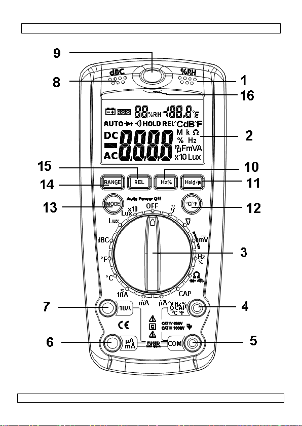
5. Overview and use
Refer to the illustrations on page 2 of this manual.
1 humidity & temperature sensor
measure room temper at ur e and r elative humidity
2 LCD
select function
4 V/Hz%/Ω/Cap/ °C input
input jack for V, Hz%, Ω, Cap or °C measurement (red lead)
5 COM input
input jack for µA or mA range measurement (red lead)
7 10A input
input jack for 10A range measurement (red lead)
8 microphone
22/08/2013 ©2008 Velleman® Components nv
4
Page 5

DVM601
9
light sensor
long life silicon light s en s or diode
10
Hz/% button
Switch room temperature reading between ° C and °F
13
mode button
diode and continuity test.
14
range button
this value. Press again to exit relative measurement mode.
voltages
switch to Hz/% measurement – available when measuring AC/DC
voltage, AC/DC current and Hz/%
11 hold/backlight button
Freeze/unfreeze all values on the display. Press and hold for ±3s to
switch backlight on/off.
12 °C/°F mode button
Switch between AC and DC current measurement; switch between Ω,
Select displayed measurement range manually.
15 REL button
Press to store the current measuring result and start measuring against
16 Non-Contact Voltage (NCV) indicator
turns on when the built-in non-contact AC voltage detector detects AC
6. Use
General
• When the range of the measured signal is unknown, start measurement
in auto-range mode, and then select range according to indicated value.
• The display shows “OL” when the present range limit is exceeded. Select
a higher range to continue measurement.
• Do not measure voltages > 600 V or current higher than 500mA (mA/µA
jack [6]) or 10 A (10A jack [7]). Note that t he meter can only handle
10A for less than 30 seconds (with 15 minutes cool-down time).
• The device will go in sleep mode when no activity is detected for ±30
minutes. Press any button to re-activate.
Sound level measurement
• Set the rotary switch [3] to the dBC-position.
• Point the microphone [8] t oward s t he sound source for more accurat e
measurement. The sound level will be displayed.
Note: st r ong wind (over 10m/s) will have a negative impact on the
measurement.
Humidity measurement
• Set the rotary switch [3] to any position (except OFF).
• The relative humidity at the current location is measured ([1]) and t he
value is shown on the top line of the LCD [2]. For more accurate results,
let the multimeter acclimatize for ±2h bef ore measur ing.
22/08/2013 ©2008 Velleman® Components nv
5
Page 6
DVM601
Light measurement
• Set the rotary switch [3] to the Lux- or Lux 10x-position.
• Point the light sensor [9] towards the light source f or more accurate
measurement. The light level wi ll b e d isplayed [7].
Note: sensor calibrated to standard incandescent lamp @ 2856K
Room temperature
• Set the rotary switch [3] to any position (except OFF).
• The room temperature at the current location is measured ([1]) and the
value is shown on the top line of the LCD [2].
Thermocouple temperature
• Set the rotary switch [3] in the °C or °F position. Do not apply input
voltage at this setting!
• Insert the thermocou p le a d ap tor into the temp input [4] and COM input
[5].
• Plug the thermocouple itself into the adaptor (if not done yet). There is
only one way possible, do not f orce.
• Use the other end of the thermocouple to measure temperatures.
Temperature is shown on the LCD [5].
Notes:
• do not expose the multi-meter itself to t emper at ur es lower than 0°C
(32°F) or higher th an 40° C (104°F).
• Do not change the probe, as this will influence measuring accuracy.
AC/DC voltage measurement
• Connect the red test lead to the V input jack [4] and the black lead to
the COM input jack [5].
• Set the rotary switch [3] in the desired position (V , V , mV ). If
the voltage to be measured is unknown beforehand, set the range switch
in the highest range position and then reduce gradually until the ideal
resolution is obtained.
• Use the mode button [13] to choose between AC and DC voltage.
• Connect the test leads to the source being measured.
• Read the voltage value on the LCD display [2] along with the polarity of
22/08/2013 ©2008 Velleman® Components nv
6
Page 7
DVM601
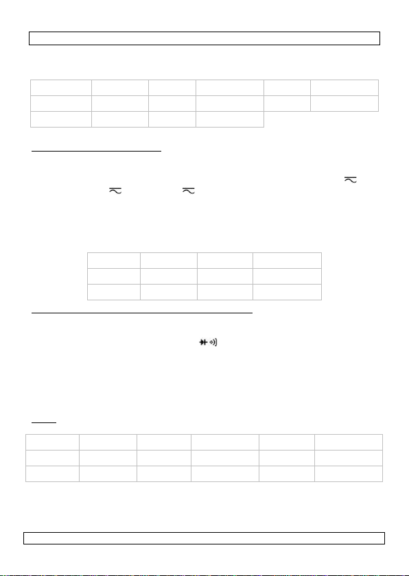
Range
Resolution
Range
Resolution
Range
Resolution
400.0mV*
0.1mV
40.00V
10mV
600V
1V
4.000V
1.0mV
400.0V
100mV
Range
Resolution
Range
Resolution
400.0µA
0.1µA
400.0mA
100µA
4000µA
1µA
10A
10mA
Range
Resolution
Range
Resolution
Range
Resolution
4.000kΩ
1Ω
400.0kΩ
100Ω
40.00MΩ
1MΩ
the red lead connection.
• Press the Hz/% button to switch to frequency; press again to see the
duty cycle (%).
*: no auto-ranging for AC
AC/DC current measurement
• Connect the red test lead to the µA/mA [6] input jack (max. 400mA) or
10A [7] input jack and the black test lead to the COM jack [5].
• Set the rotary switch [3] in the desired current range (<4mA: µA ,
<400mA: mA , <10A: 10A ) and use the mode button [3] to
choose between AC and DC current.
• Open the circuit in which the current is to be measured and connect the
test leads to the circuit IN SERIES.
• Read the current value and the polarity of the red lead connection on the
LCD display.
Resistance, diode test and aud ible continu ity t est
• Connect the red test lead to the Ω-jack [4] and the black test lead to the
COM jack [5] (the red lead has a positive polarity "+").
• Set the rotary switch [3] in the Ω range position. Do not apply input
voltage at this setting!
• Use the mode button [13] to choose between Ω, diode or continuity test.
• If the resistance being measured is connected to a circuit, turn off the
power and discharge all capacitors before applying the test probes.
• Connect the test leads to the resistor to be measured and read the LCD
display.
Note: wait a few seconds for a stable reading when measuring resist ors >
1MΩ.
400.0Ω 0.1Ω 40.00KΩ 10Ω 4.000MΩ 10kΩ
• For diod e t e s t s , connect the r ed test lead to the anode of the diode to be
tested and the black test lead to the cathode of the diode. The approx.
forward voltage d rop of the diode will b e d is p lay e d (typically 0.400 –
0.700V). If the connection is reversed, t he display will show “OL”.
22/08/2013 ©2008 Velleman® Components nv
7
Page 8

DVM601
• For continuity tests, connect the test leads to two points of the circuit to
be tested. If continuity exists (resistance < 50Ω), the built-in buzzer will
sound. If the circuit is open, “OL” will be ind ic ated.
Non-contact AC voltage test
• Set the rotary switch [3] to any position (except OFF).
• The AC-sensor is located at the top of the meter, near the light sensor
[9]. Point the AC-sensor towards the suspect ed AC-source. When AC
voltage is present, the indicator [16] will light up. The stronger the ACsource, the more the indicator [16] will be lit.
7. Battery
• When the low bat tery indicat ion ( ) appears, replace the internal
batteries. Turn the rotary switch [3] to the OFF-position.
• Always disconnect tes t lea ds when replacing the battery. Do not us the
device without batteries i nstal led.
• The battery cover is lo cated on the back of t he device and is clos ed with two
screws. Remove t he screws and o pen the bat tery compart ment.
• Rem ove the battery and insert a new 9V (E -block) battery following the
polarity as i ndicat ed i n t he batt er y holder .
• Reinstall the co ver and secure it with the tw o screws.
•
Remove the battery when the device is not in use for a longer period of time to
avoid leakage.
• Do not attempt to recharge non-rechargeable batteries, do not puncture and do
not throw in fire as they may explode.
WARNING : h andle batte ries with care, observe warnin gs on
battery casing. Dispose of batteries in accordance with local
regulations.
Keep batteries away fr o m child r en.
8. Fuses
• To replace an internal fuse, turn the rotary switch [3] to the OFF-position.
• Always disconnect tes t lea ds when replacing fuses. Do not use the devic e
without the p rop er f uses installed.
• The acce ss the fuses, the whol e back cover must be r emo ved. Loosen the 6
outer screws (2 are located under the foldable stand). Do not remove the
battery cover screws (see §7) . Lift the whole back cover. Do not touch the
electronic circuitry inside.
• Replace fuses only by new ones with following specifications:
• Close the back cover and secure the 6 screws.
• Fuse 1 (large): F 10A/60 0V fa st blow
• Fuse 2 (small): F 500mA/660V fast blow
Using wrong fuses or short-circuiting fuse holders can lead to
potentially life-threatening situations.
22/08/2013 ©2008 Velleman® Components nv
8
Page 9
DVM601
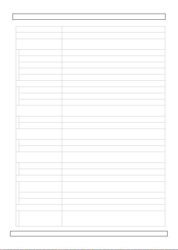
9. Technical specifications
capacitance overload p r otection - 600 V AC or DC
frequency sensitivity < 1MHz: >0.5V RMS / > 1MHz: >3V RMS
sound level
measurements
resolution 0.1dB
typ. instrument freq. 30Hz to 10kHz
frequency we ighti ng C
accuracy ± 5dB at 94dB sound level (1kHz sine wave)
microphone electric condenser
light measurem ents up to 40 000lux
accuracy ± 5% of rdg + 10 digits
temp. characteristics ±0.1%/°C
photodiode 1 silicon p hotodiode with filter
humidity
measurements
resolution 1% RH
accuracy ±3% RH
internal temperature
measurements
resolution 0.1°C
accuracy 3% of rdg ± 5 digits
K-type th ermoc ouple
measuring range
resolution 1°C
accuracy 3% of rdg ± 5 digits
DC voltage 400mV/4V/40V/400V/600V
basic accuracy ± 1.0% of rdg ± 4 digits for 0.4V~40V range / ±
input impedance 10Mohm
maximum input 600V
AC voltage 400mV/4V/400V/600V
basic accuracy ± 1.5% of rdg ± 15 digits for 400mV range / ±
22/08/2013 ©2008 Velleman® Components nv
35-100dB
33%~99% RH
0°C to +50°C
-20°C ~ +1300°C
1.5% of rdg ± 4 digits for 400V~600V range
1.0% of rdg ± 4 digits for 4V~40V range / ± 1.5%
of rdg ± 4 digits for 400V~600V range
9
Page 10
DVM601
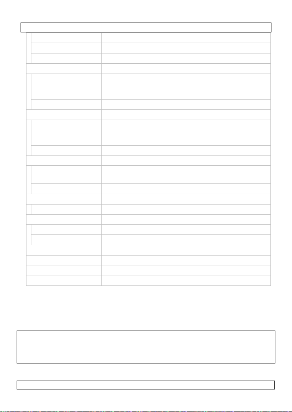
input impedance 10Mohm
frequency range 50 to 400Hz
maximum input 600Vac
DC current 400µ/4m/400m/10A
basic accuracy ± 1.0% of rdg ± 2 digits for 400µA~4mA range/ ±
1.2% of rdg ± 2 digits for 400mA range / ± 2.0%
of rdg ± 5 digits for 10A range
overload protection 500mA/600V fuse & 10A/600V fuse
AC current 400µ/4m/400m/10A
basic accuracy ± 1.2% of rdg ± 2 digits for 400µA~4mA range/ ±
1.5% of rdg ± 2 digits for 400mA range / ± 2.0%
of rdg ± 5 digits for 10A range
overload protection 500mA/600V fuse & 10A/600V fuse
resistance 400/4k/40k/400k/4M/40M
basic accuracy ± 1.5% of rdg ± 4 digits for 400 ohms range / ±
1.5~2.0% of rdg ± 2 digits f or 4k~40M r ang e
overload protection 15 seconds max. 250V on all ranges
capacitance 50.00nF/500.0nF/5.000uF/50.00uF/100.0uF
accuracy ±3.0~5.0% of rdg ± 5~7 d igit s
frequency 5Hz/50Hz/500Hz/5KHz/50KHz/500KHz/10MHz
basic accuracy ±1.2% of rdg ± 3digits
overload protection 250V AC or DC
maximum display 3999
pow er supply 9V battery (E-block)
dimensions 170 x 78 x 48mm
weight (with battery) app r ox. 330g
Use this device with orig in al accessories only. Velleman nv cannot be held
respons ible in the e v en t of damage or in jury resulted from (incorrect) use
of this device. For more info concerning this product, please visit our
website www.velleman.eu.
The information in this manual is subjec t to change with ou t prior notice.
© COPYRIGHT NOTICE
This manual is copyrighted. The copyright to this m a nual is owned by Velleman Components
nv. All worldwide rights reserved. No part of this manual may be copied, reproduced, translated or
reduced to any electronic medium or otherwise without the prior written consent of the copyright
holder.
22/08/2013 ©2008 Velleman® Components nv
10
Page 11
DVM601
serveonderdelen
GEBRUIKERSHANDLEIDING
1. Inleiding
Aan alle ingezetenen van de Europese Unie
Belangrijke milieu-informatie betreffende dit product
Respecteer de plaatselijke milieuwetgeving.
Hebt u vragen, contacteer dan de plaatselijke autoriteiten betreffende de
verwijdering.
Dank u voor uw aankoop! Lees deze handleiding grondig voor u het toestel in
gebruik neemt. Werd het toestel beschadigd tijdens het transport, installeer het
dan niet en raadpleeg uw dealer.
2. Veiligheidsinstructies
• De garantie geldt niet voor schade door het negeren van bepaalde richtlijnen in
• Schade door wijzigingen die de gebruiker heeft aangebracht valt niet onder de
3. Algemene richtlijnen
• Bescherm dit toestel tegen schokken. Vermijd brute kracht tijdens de
• Bescherm tegen extreme hitte (bv. direct zonlicht) en stof.
• Bewaar of gebruik dit toestel niet in een vochtige omgeving of bij een hoge
• Leer eerst de functies van het toestel kennen voor u het gaat gebruiken.
• Gebruik de oorspronkelijke verpakking wanneer u het toestel vervoert.
• Om veiligheidsredenen mag u geen wijzigingen aanbrengen.
22/08/2013 ©2008 Velleman® Components nv
Dit symbool op het toestel of de verpakking geeft aan dat, als het na
zijn levenscyclus wordt weggeworpen, dit toestel schade kan
toebrengen aan het milieu. Gooi dit toestel (en eventuele batterijen)
niet bij het gewone huishoudelijke afval; het moet bij een
gespecialiseerd bedrijf terechtkomen voor recyclage. U moet dit toestel
naar uw verdeler of naar een lokaal recyclagepunt brengen.
Enkel voor gebruik binnenshuis. Bescherm tegen regen, vochtigheid en
opspattende vloeistoffen.
Houd buiten het bereik van kinderen en onbevoegden.
Elektrocutiegevaar tijdens de bediening. Wees voorzichtig bij het
meten van een circuit onder spanning.
U mag geen onderdelen vervangen. Bestel eventuele re
bij uw dealer.
deze handleiding en uw dealer zal de verantwoordelijkheid afwijzen voor
defecten of problemen die hier rechtstreeks verband mee houden.
garantie.
bediening.
omgevingstemperatuur, of in de buurt van brandbare stoffen en sterke
magnetische velden.
11
Page 12

DVM601
1
vochtigheid- en temperatuursensor
meet de omgevingstemperatuur en de relatieve vochtigheidsgraad
2
lcd-scherm
lcd-scherm van 3
digits
3
draaischakelaar
silicium lichtsensor met lange levensduur
• Gebruik het toestel enkel waarvoor het gemaakt is. Bij onoordeelkundig gebruik
vervalt de garantie.
• L et op: elektrocutiegevaar tijdens het meten van een spanning > 36 VDC,
25 VAC, een stro om > 10 mA, AC elektrische leidingen me t een inductielast en AC
elektrische leidingen met een fluctuerende stroom.
• Gebruik enkel de meegeleverde testsnoeren en vervang ze d oor identieke
exemplaren indien nodig.
• Ga voor elke meting na o f d e aansluitingen correct e n vei lig zij n.
• Stel het toestel op het correcte bereik in voor elke meting.
• Raak tijdens het m e te n gee n ci r cuit ( bv. te rmi n al s, stopcontac t en, enz .) onder
spanning aan. Zorg ervoor dat u tijdens het me ten geïsoleerd bent.
• Overschrij d noo i t d e wa a r de n ver meld achter a a n d e ha n dl ei ding.
• Laat het toeste l ij ken en repareren door een ge schoold technicus. Neem contact
op met uw dealer.
• Meet nooit een sp anning indien het toestel is aangesloten aan een terminal.
4. Eigenschappen
• CAT. III – 1000 V, CAT. IV – 600 V
• meting van geluidsniveau, licht, vochtigheid, temperatuur, DC- en AC-spanning,
DC- en AC-stroom, frequentie, capaciteit, weerstand, diodes, doorlaatspanning,
kabels onder spanning...
• aanduiding bij zwakke batterij
• automatische bereikinstelling (uitgenomen bereiken VAC 400 mV, IAC 10 A en
IDC 10 A)
• ingebouwde contactloze AC spanningsdetector (50 ~ 1.000 VAC)
5. Omschrijving
Raadpleeg de figur en op pagi n a 2 van deze handleiding.
4/5
selecteert de functie
4 V/Hz%/Ω/Cap/°C
ingangsbus voor V-, Hz%-, Ω-, cap- of °C-metingen (rood meetsnoer)
5 COM
gemeenschappelijke ingangsbus (zwart meetsnoer)
6 µA/mA
ingangsbus voor µA- of mA-metingen (rood meetsnoer)
7 10A
ingangsbus voor 10A-metingen (rood meetsnoer)
8 microfoon
condensatormicrofoon voor geluidsmet ing en
9 lichtsensor
22/08/2013 ©2008 Velleman® Components nv
12
Page 13
DVM601
10
Hz/%
13
MODE
diode en doorverbinding
14
RANGE
meetmodus te verlaten
16
aanduiding contactloze meting (Non-Contact Volta ge of NCV)
verschi jnt op de di s pl a y bij contactloze meting van een AC-spanning
schakelaarvoor switch Hz-/%-metingen – beschikbaar bij meting van AC- en
DC-spanning, AC- en DC-stroom en Hz/%
11 HOLD/achtergrondverlichting
bevriest de uitlezing op de display – houd gedurende ± 3 seconden ingedrukt
om de achtergrondverlichting in of uit te schakelen
12 °C/°F
selectietoets tussen temperatuurweergave in °C en °F
selectietoets tussen meting van AC- en DC-stroom – selecteer tussen Ω,
handmatige instelling van het bereik
15 REL
druk in om de huidige uitlezing in het geheugen op te slaan en als referentie
voor verdere metingen te gebruiken – druk opnieuw in om de relatieve
6. Gebruik
Algemeen
• Indien u het bereik niet kent, start de meting met de automatische
bereikinstelling en kies het gepaste bereik aan de hand van de eerste
meetresultaten.
• De display geeft ‘OL’ weer indien het bereik overschreden wordt. Selecteer een
hoger bereik.
• Meet geen spanning > 600 V of stroom > 500 mA (mA/µA-bus [6]) of 10 A
(10A-bus [7]). De multimeter aanvaardt een stroom van 10 A gedurende
minder dan 30 seconden (met koeling van 15 minuten).
• Het toestel schakelt naar stand-by na ± 30 minuten seconden inactiviteit. Druk
op een toets om verder te gaan.
Meten van geluidsniveau
• Plaats de draaischakelaar [3] op dBC.
• Richt de microfoon [8] naar de geluidsbron voor een precieze meting. Het
geluidsniveau wordt weergegeven.
Opmerking: Een meting bij sterke wind (> 10 m/s) zal de resultaten negatief
beïnvloeden.
Meten van de vochtigheidsgraad
• Plaats de draaischakelaar [3] op een van de functies (uitgenomen op OFF).
• De sensor [1] meet onmiddellijk de relatieve vochtigheidsgraad en geeft die
weer op de display [2]. Voor een precieze meting laat u de multimeter
gedurende ± 2 uur aan de omgeving acclimatiseren alvorens u begint te meten.
Meten dan de lichtsterkte
• Plaats de draaischakelaar [3] op Lux of op Lux 10x.
22/08/2013 ©2008 Velleman® Components nv
13
Page 14

DVM601
• Richt de sensor [9] naar de lichtbron voor een precieze meting. De lichtsterkte
wordt op de display [7] weergegeven.
Opmerking: De sensor werd geijkt met een gloeilam p @ 2856K.
Meten van de omgevingstemperatuur
• Plaats de draaischakelaar [3] op een van de functies (uitgenomen op OFF).
• De sensor [1] meet onmiddellijk de omgevingstemperatuur en geeft die weer
op de displ ay [2].
Meten van de temperatuur via het thermokoppel
• Plaats de draaischakelaar [3] op °C of op °F. Breng op deze functie geen
spanning aan!
• Koppel de adapter aan de °C-bus [4] en de COM-bus [5].
• Steek het thermokoppel zonder te forceren in de adapter.
• Meet de temperatuur met het thermokoppel. De temperatuur verschijnt op de
display [5].
Opmerkingen:
• Bescherm de multimeter tegen temperaturen < 0°C (32°F) of > 40°C
(104°F).
• Om de nauwkeurigheid niet te beïnvloeden, is het aan te raden de sonde niet
te wijzige n.
Meten van AC- en DC-spanning
• Koppel het rode meetsnoer aan de V-bus [4] en het zwarte meetsnoer aan de
COM-bus [5].
• Plaats de draaischakelaar [3] op de gewenste functie (V , V , mV ).
Indien u het bereik niet kent, start de meting op het hoogste bereik en
kies het gepaste bereik aan de hand van de eerste meetresultaten.
• Kies voor AC- of DC-meting met MODE [13].
• Koppel de meetsnoeren aan het te meten circuit.
• Lees het meetresultaat en de polariteit van het rode meetsnoer af van de
display
• Druk de Hz/%-toets in om de frequentie om te schakelen, druk opnieuw in de
22/08/2013 ©2008 Velleman® Components nv
[2].
duty cycle (%) weer te geven.
14
Page 15
DVM601
Bereik
Resolutie
Bereik
Resolutie
Bereik
Resolutie
400,0 mV*
0,1 mV
40,00 V
10 mV
600 V
1 V
4,000 V
1,0 mV
400,0 V
100 mV
Bereik
Resolutie
Bereik
Resolutie
400,0 µA
0,1 µA
400,0 mA
100 µA
4.000 µA
1 µA
10 A
10 mA
400,0 Ω
0,1 Ω
40,00 kΩ
10 Ω
4,000 MΩ
10 kΩ
4,000 kΩ
1 Ω
400,0 kΩ
100 Ω
40,00 MΩ
1 MΩ
Meten van AC- en DC-stroom
• Koppel het rode meetsnoer aan de µA/mA-bus [6] (max. 400 mA) o f de 10 A-
bus [7] en het zwarte meetsnoer aan de COM-bus [5].
• Plaats de draaischakelaar [3] op het gewenste bereik (< 4 mA: µA ,
< 400 mA: mA , < 10 A: 10A ) en kies voor AC- of DC-meting met MODE
[13].
• Open het circuit en koppel de meetsnoeren in serie.
• Lees het meetresultaat en de polariteit van het rode meetsnoer af van de
*: geen automatische bereikinstelling voor AC-meting
display [2].
Meten van weerstand, di o des en doorverbinding
• Koppel het rode meetsnoer aan de Ω-bus [4] en het zwarte meetsnoer aande
COM-bus [5] (het rode meetsnoer is positief +).
• Plaats de draaischakelaar [3] op het Ω -bereik. Breng op deze functie
geen spanning aan!
• Kies tussen voor Ω-, diode- of doorverbindingmeting met MODE [13].
• Onderbreek de stroom van het circuit en ontlaad alle condensatoren
alvorens de meetsnoeren aan de weerstand te koppelen.
• Koppel de meetsnoeren aan de te meten weerstand en lees het meetresultaat
af van de display
Opmerking: Bij het meten van weerstand > 1 MΩ st a b ilise e r t de uitlezing
zich pas na enkele seconden.
Bereik Resolutie Bereik Resolutie Bereik Resolutie
• Voor de diodetest, koppel het r ode meetsnoer aan de anode en het
zwarte meetsnoer aan de kathode van de diode. Het voorwaartse
spanningsverlies van de diode wordt op de display afg ebeeld
0,400 ~ 0,700 V). Bij een omgekeerde aansluiting verschijnt ‘OL ’.
• Voor de doorverbindingtest, koppel de meetsnoeren aan twee p unt en van
het te meten circuit. Bij goede doorverbinding (weerstand
[2].
(typisch
< 50 Ω) piept
de multimeter. Bij een open circuit verschijnt ‘OL’.
22/08/2013 ©2008 Velleman® Components nv
15
Page 16

DVM601
Contactloze meting van AC-spanning
• Plaats de draaischakelaar [3] op een van de functies (uitgenomen op OFF).
• Richt de AC-sensor [9] naar de AC-bron. Bij een AC-spanning zal de aanduiding
[16] oplichten. Hoe sterker de AC-bron, des te licht de aanduiding op.
7. De batterij
• Vervang de batterijen van zodra ( ) op de display verschijnt. Draai de
schakelaar [3] in de OFF-stand.
• Ontkoppel het toestel van het circuit alvorens de batterijen te vervangen. Koppel
nooit een toestel zond er batterijen aan het circuit.
• Verwijder de schroeven achteraan het toestel en open het batterijvak.
• Verwijder de batterij en plaats een nieuwe volgens de polariteitaanduidingen.
• Sluit het batterijvak.
• Verwijder de batterijen uit het toestel na gebruik.
• Herlaad geen alkalinebatterijen en gooi ze nooit in het vuur.
LET OP: Vo lg de rich tlijnen op de v erpakking v a n de batterij .
Houd de ba t terij buiten bereik v an kinderen
8. De zekeringen
• Draai de schakelaar [3] in de OFF-stand alvorens de zekering te vervangen.
• Ontkoppel het toestel van het circuit alvorens de batterijen te vervangen. Koppel
nooit een toestel zond er zekeringen aan het circuit.
• Open de volledige behuizing. Verwijder hiervoor de zes schroeven achteraan het
toestel zonder die van het batterijvak te verwijderen (zie §7). Raak het interne
circui t v an de multimeter nie t aan.
• Vervang de zekeringen door identieke exemplaren:
• zekering 1 (grote): F 10 A/600 V, sn el
• zekering 2 (kleine): F 500 mA/660 V, snel
Het gebruik van zekeringen van een ander type of het kor ts luiten va n de
houders is levens gevaarlijk en kan het toestel ern stig beschadigen .
• Sluit de behuizing en maak vast met de zes schroeven.
9. Technische specificaties
capaciteit bescherming overbelasting – 600 V AC of DC
frequentiegevoeligheid < 1 MHz: > 0,5 V RMS/> 1 MHz: > 3 V RMS
geluidsniveaumetingen 35 ~ 100 dB
resolutie 0,1 dB
typische frequentie 30 Hz ~ 10 kHz
frequentieweging C
nauwkeurigheid ± 5 dB @ 94 dB (1 kHz s inusgolf)
microfoon condensator
22/08/2013 ©2008 Velleman® Components nv
16
Page 17

DVM601
lichtmetingen tot 40.000 lux
nauwkeurigheid ± 5 % v.d. afl. + 10 digits
eigenschappen temp. ± 0,1 %/°C
fotodiode 1 silicium fotodiode met filter
vochtigheidsmetingen 33 % ~ 99 % RH
resolutie 1 % RH
nauwkeurigheid ± 3 % RH
interne
temperatuurmetingen
resolutie 0,1°C
nauwkeurigheid 3 % v.d. afl. ± 5 digits
meetbereik
thermokoppel type K
resolutie 1°C
nauwkeurigheid 3 % v.d. afl. ± 5 digits
DC-spanning 400 mV/4 V/40 V/400 V/600 V
basisnauwkeurigheid ± 1,0 % v.d . af l. ± 4 digits voor 0,4 V ~ 40 V/
ingangsimpedantie 10 MΩ
max. ingang 600 V
AC-spanning 400 mV/4 V/400 V/600 V
basisnauwkeurigheid ± 1,5 % v.d . af l. ± 15 digits voor 400 mV/
ingangsimpedantie 110 MΩ
frequentiebereik 50 ~ 400 Hz
max. ingang 600 VAC
DC-stroom 400 µ/4 m/400 m/10 A
basisnauwkeurigheid ± 1,0 % v.d. afl. ± 2 digits voor 400 µA ~ 4 mA/
bes cherming tegen
overbelasting
0°C ~ +50°C
-20°C ~ +1.300°C
± 1,5 % v.d. afl. ± 4 digits voor 400 V ~ 600 V
± 1,0 % v.d. afl. ± 4 digits voor 4 V ~ 40 V/
± 1,5 % v.d. afl. ± 4 digits voor 400 V ~ 600 V
± 1,2 % v.d. afl. ± 2 digits voor 400 mA/
± 2,0 % v.d. afl. ± 5 digits voor 10 A
500 mA/600 V-zekering & 10 A/600 V-zekering
22/08/2013 ©2008 Velleman® Components nv
17
Page 18

DVM601
AC-stroom 400 µ/4 m/400 m/10 A
basisnauwkeurigheid ± 1,2 % v.d . af l. ± 2 digits voor 400 µA ~ 4 mA/
bescherming tegen
overbelasting
weerstand 400/4 k/40 k/400 k/4 M/40 M
basisnauwkeurigheid ± 1,5 % v.d . af l. ± 4 digits voor 400 Ω/
bescherming tegen
overbelasting
capaciteit 50,00 nF/500,0 nF/5,000 uF/50,00 uF/100,0 uF
nauwkeurigheid ± 3,0 ~ 5,0 % v.d. afl. ± 5 ~ 7 digits
frequentie 5 Hz/50 Hz/500 Hz/5 kHz/50 kHz/500 kHz/10 MHz
basisnauwkeurigheid ± 1,2 % v.d . af l. ± 3 digits
bescherming tegen
overbelasting
max. display 3999
voeding 9 V-batterij (type E)
afmetingen 170 x 78 x 48 mm
gewicht met batterij ± 330 g
Gebruik dit toestel enkel met originele accessoires. Velleman nv is niet
aansprakelijk voor schade of kwetsuren bij (verkeerd) gebruik van di t
toestel. Voor meer informatie over dit pr oduct, zie www. velleman.eu. De
info rma t ie in deze ha n dleiding k an t e a llen tijde wo rden gewijz igd zonder
voorafgaande k e nnisgevi ng.
© AUTEURSRE CH T
Velleman Components nv heeft het auteursrecht voor deze handleiding.
Alle wereldwijde rechten voorbehouden. Het is niet toegestaan om deze
handleiding of gedeelten ervan over te nemen, te kopiëren, te vertalen, te
bewerken en op te slaan op een elektronisch medium zonder voorafgaande
schriftelijke toestemming van de rechthebbende.
± 1,5 % v.d. afl. ± 2 digits voor 400 mA/
± 2,0 % v.d. afl. ± 5 digits voor 10 A
500 mA/600 V-zekering & 10 A/600 V-zekering
± 1,5 ~ 2,0 % v.d. afl. ± 2 digits voor 4 k ~ 40 MΩ
15 seconden max. 250 V voor alle bereiken
250 V AC of DC
22/08/2013 ©2008 Velleman® Components nv
18
Page 19

DVM601
NOTICE D’EMPLOI
1. Introduction
Aux résidents de l'Union européenne
Des informations environnementales importantes concernant ce produit
la ré gleme ntat ion locale relative à la protection de l’environnement.
En cas de questions, contacter les autorités locales pour élimination.
Nous vous remercions de votre achat ! Lire la présente notice attentivement avant
la mise en service de l’appareil. Si l’appareil a été endommagé pendant le
transport, ne pas l’installer et consulter votre revendeur.
2. Consignes de sécurité
• La garantie ne s’applique pas aux dommages survenus en négligeant certaines
• Les dommages occasionnés par des modifications à l’appareil par le client ne
3. Directives générales
• Protéger le multimètre contre les chocs et le traiter avec circonspect ion
• Tenir le multimètre à l’écart de la poussière, de l’humidité et des
• Stocke r le multimètre dans un endroit sec et propre, et à l’écart de hautes
• Se familiariser avec le fonctionnement de l’appareil avant de l’utiliser.
• Toute modification de l’appareil est interdite pour d es raisons de sécurité.
• N’utiliser le multimètre q u’à sa fonction prévue. Un usage impropre
22/08/2013 ©2008 Velleman® Components nv
Ce symbole sur l'appareil ou l'e mballage indique q ue l’élimina tion d’un
appareil en fin de vie peut polluer l'environnement. Ne pas jeter un
appareil électrique ou électronique (et des piles éventuelles) parmi les
déchets municipaux non sujets au tri sélectif ; une déchèterie traitera
l’appareil en question. Renvoyer les équipements usagés à votre
fournisseur ou à un service de recyclage local. Il convient de respecter
Pour usage à l’intérieur uniquement. Tenir le multimètre à l’écart de la
pluie, de l’humidité et de projections d’eau.
Garder le multimètre hors de la portée de personnes non qualifiées et
de jeunes enfants.
Risque d’électrochoc pendant l’utilisation de ce multimètre.
Procéder avec précaution lors de la mesure d’un circuit sous tension.
Il n’y a aucune pièce maintenable par l’utilisateur. Commander d es
pièces de rechange éventuelles chez votre revendeur.
directives de cette notice et votre revendeur déclinera toute responsabilité pour
les problèmes et les défauts qui en résultent.
tombent pas sous la garantie.
pendant l’opération.
températures extrêmes.
températures, de gaz explosifs ou de champs magnétiques.
annule d'office la garantie.
19
Page 20

DVM601
3
sélecteur rotatif
sélecteur de fonction
prise d’entrée pour mesure V, Hz%, Ω, cap ou °C (cordon rouge)
prise d’entrée commune (cordon noir)
6
µA/mA
prise d’entrée pour mesure µA ou mA (cordon rouge)
7
10A
prise d’entrée pour mesure 10 A (cordon rouge)
8
microphone
microphone à condensateur pour mesure de niveau sonore
diode en silice long ue durée
• Attention : Risque d’électrochoc lors de mesures de tensions > 36 VCC,
25 VCA, c ourants > 10 mA, lignes électriques CA avec cha rg e inductive et
lignes électriques CA avec fluctuations.
• N’utiliser ce multimètre qu’avec les sondes incluses. Remplacer les sondes
par des sondes i den tiques.
• S’assurer que les connexions soient dûment établies.
• Sélectionner la ga mme avant c haque me sure.
• Évi ter de touc her des cosses mét alliq ues, les sondes, etc. pend a nt l a
mes ure. Veiller à vous i soler é le ctriq uement.
• Ne jamais appliquer une tension ou un courant ex cédant l es spécifications
men tionnées à la fin de cet te noti ce.
• Confier l’étalonnage et l ’entret ien à un technicien qualifié.
• Ne pas mesurer de tensions lors que la fonction de mesure de courant est
sélectionnée.
4. Caractéristiques
• CAT. III – 1.000 V, CAT. IV – 600 V
• mesures : niveau sonore, luminosité, humidité, température, tensions CA et
CC, courants CA et CC, fréquence, capacité, résistance, diodes, continuité,
câblage sous tension...
• indication de pile faible
• sélection automatique de la gamme (exceptées gammes VCA 400 mV, ICA 10 A
et ICC 10 A)
• fonction incorporée pour la détection sans contact de tensions CA (50 ~
1.000VCA)
5. Description
Se référer à l’illustration à la page 2 de cette notice.
1 capteur de température et d’humidité
mesure de la température ambiante et de l’humidité relative
2 LCD
afficheur LCD 3
4 V/Hz%/Ω/Cap/°C
5 COM
4/5
digits
9 capteu r photosensible
22/08/2013 ©2008 Velleman® Components nv
20
Page 21

DVM601
10
Hz/%
13
MODE
continuité
14
RANGE
mesure Hz/% – disponible lors de mesure de tensions et courants CA/CC, et
Hz/%
11 HOLD/rétro-éclairage
gel de la valeur mesurée sur l’afficheur – maintenir enfoncé pendant ± 3
secondes pour activer/désactiver le rétro-éclairage
12 °C/°F
affichage de la température en °C/°F
sélection de mesure de courants CA/CC – sélection de mesure Ω, diode et
sélection manuelle d e la gamme
15 REL
enfoncer pour mettre la valeur affichée en mémoire et pour l’utiliser comme
référence – renfoncer pour quitter le mode de mesure relative
16 indicateur de mesure sans contact (Non-Contac t V oltage ou NCV)
s’affiche lors d’une mesure sans contact de tension CA
6. Emploi
En général
• Démarrer la mesure avec la fonction de sélection de gamme automatiq ue
lorsque l’étendue de la gamme est inconnue.
• Une mesure hors plage est indiquée par « OL ». Sélectionner une gamme
supérieure.
• Ne pas mesurer des tensions > 600 V ou des courants > 500 mA (p rise VΩmA
[6]) ou 10 A (prise 10 A [7]). Le multimètre peut subir un courant de 10 A
pendant 30 secondes (avec un délai de refroidissement de 15 minutes).
• Le multimètre se met en mode veille après un délai de ± 30 minutes. Enfoncer
une touche pour continuer.
Mesure du niveau sonore
• Placer le sélecteur rotatif [3] sur dBC.
• Pointer le microphone [8] vers la source sonore. Le niveau sonore s’affiche.
Remarque : Effectuer une mesure par vent fort (>10 m/s) aura une influence
négative sur le résultat.
Mesure de l’hu midité relative
• Placer le sélecteur rotatif [3] sur une fonction quelconque (excepté sur OFF).
• Le multimètre mesure automatiquement l’humidité relative [1] et affiche la
vale ur sur le LC D [2]. Pour une mesure plus précise, laisser le multimètre
s’acclimater pendant ± 2 heures.
Mesure d’intensité lumineuse
• Placer le sélecteur rotatif [3] sur Lux ou sur Lux 10x.
• Pointer le capteur photosensible [9] vers la source lumineuse. L’intensité
lumineuse s’affiche sur le LCD [2].
22/08/2013 ©2008 Velleman® Components nv
21
Page 22

DVM601
Plage
Résolution
Plage
Résolution
Plage
Résolution
4,000 V
1,0 mV
400,0 V
100 mV
Remarque : Le capteur photosensible est étalonné avec une lampe à
incandescence @ 2856K.
Mesure de la température ambiante
• Placer le sélecteur rotatif [3] sur une fonction quelconque (excepté sur OFF).
• Le multimètre mesure automatiquement la température ambiante [1] et affiche
la valeur sur le LCD [2].
Mesure de la température à l’aide du thermocouple
• Placer le sélecteur rotatif [3] sur °C ou sur °F. Ne pas appliquer de tension
d’entrée sur cette fonctio n !
• Insérer l’adaptat eur dans les prises °C/°F [4] et COM [5].
• Insérer délicatement le thermocouple dans l’adaptateur.
• Mesurer la température à l’aide du thermocouple. La température s’affiche sur
le LCD [5].
Remarque :
• Ne jamais exposer le multimètre à une température < 0°C (32°F) ou > 40°C
(104°F).
• Ne jamais modifier le thermocouple afin de ne pas influencer négativement
les mesures de température.
Mesure de tensions CA/CC
• Insérer le cordon r ouge d ans la prise V [4] et le cordon noir dan s la prise
COM [5].
• Placer le sélecteur rotatif [3] sur la fonction appropr iée
). Démarrer la mesure avec la fonction de sélection de gamme
automatique lorsque l’étendue de la gamme est inconnue.
•
Sélectionner la tension CA/CC avec la touche MODE [13].
• Connecter les pointes de touche au circuit à mesurer.
• Lire la valeur affichée et la polarité de la pointe rouge sur le LCD [2].
• Enfoncer la touche Hz/% pour sélectionner la fréquence ; renfoncer la touche
pou r afficher le rappor t cyclique (%).
(V , V , mV
400,0 mV* 0,1 mV 40,00 V 10 mV 600 V 1 V
* : pas de sélection de gamme automatique lors de mesure de tension CA
22/08/2013 ©2008 Velleman® Components nv
22
Page 23

DVM601
Plage
Résolution
Plage
Résolution
4.000 µA
1 µA
10 A
10 mA
Plage
Résolution
Plage
Résolution
Plage
Résolution
400,0 Ω
0,1 Ω
40,00 kΩ
10 Ω
4,000 MΩ
10 kΩ
4,000 kΩ
1 Ω
400,0 kΩ
100 Ω
40,00 MΩ
1 MΩ
Mesure de courants CA/CC
• Insérer le cordon rouge dans la prise µA/mA [6] (max. 400 mA) ou dans la
prise 10 A [8] et le cordon noir dans la prise COM [5].
• Placer le sélecteur rotatif [3] su r la fonction appropriée (< 4 mA : µA ,
< 400 mA : mA , < 10 A : 10A ) et choisir entre le courant CA et CC
avec la touche MODE [3].
• Ouvrir le circuit et connecter les sondes EN SÉRI E au circuit.
• Lire la valeur affich ée et la polarité de la pointe rouge sur le L CD [2].
400,0 µA 0,1 µA 400,0 mA 100 µA
Mesure de la résistance, d’une diode et de continuité
• Insérer le cordon rouge dans la prise Ω [4] et le cordon noir dans la prise COM
[5] (le c ordo n rouge a une polar ité po sitiv e « + »).
• Placer le sélecteur rotatif [3] sur Ω . Ne pas appliquer de tension d’entrée
sur cette fonction !
• Sélectionner la fonction de résistance, de diode ou de continuité avec la touche
MODE [13].
• Si la résistance est connectée à un circuit, couper d’abord l’alimentation du
circuit et décharger tous les condensateurs avant de connecter les pointes de
touche.
• Connecter les pointes de touche à la résistance à mesurer et lire la valeur sur le
LCD [2].
Remarque : La valeur affichée se stabilise après quelques secondes lors des
mesures de résistances > 1 MΩ.
• Pour tester une diode, connecter la pointe de touche rouge à l’anode et la
pointe de touche noire à la cathode de la diode. La chute de tension directe
approximative d e la diode s’affiche (typiquement 0,400 V ~ 0,700 V). Une
connexion inversée est indiquée par « OL ».
• Pour tester la continuité, connecter les pointes au circuit. Une continuité
(résistance < 50 Ω) sera indiquée par une tonalité. Un circuit ouvert est
indiquée par « OL ».
Mesure sans contact d’une tension CA
• Placer le sélecteur rotatif [3] sur une fonction quelconque (excepté sur OFF).
• Pointer le capteur CA [9] vers la source de tension CA. L’indicateur [16]
s’allume lors d’une présence de tension CA. Plus cette tension est importante,
plus l’indicateur s’allume.
22/08/2013 ©2008 Velleman® Components nv
23
Page 24

DVM601
esure de niveau sonore
7. La pile
• Remplacer les piles dès que l’indication ( ) s’affiche. Placer le sélecteur rotatif
[3] sur OFF.
• Déconnecter le multimètre avant le remplacement. Ne pas utiliser un multimètre
sans piles .
• Desserrer les deux vis à l’arrière du multim ètre pour ouvrir le compartiment de la
pile.
• Retir er la pile et insérer une nouvelle pile 9 V type E en respectant la polarité.
N’utiliser que des piles identiq ues.
• Referme r l e c ompartiment des piles.
• Retirer la pile après usage.
• Ne pas recharger une pile alcalin e et ne pas la jeter au feu.
ATTENTION : Observer les directives sur l’emballage des piles.
Tenir les piles à l’écart des enfants.
8. Les fusibles
• Placer le sélecteur rotatif [3] sur OFF.
• Déconnecter le multimètre avant le remplacement. Ne pas utiliser un multimètre
sans fusibles.
• Desserrer les six vis à l’arrière du multimètr e p our ouvrir le c ompartiment des
piles. Ne pas desserrer les deux vis du compartiment de la pile (voir §7). Ne pas
toucher le circuit du multimètre.
• Remplacer les fusibles par des exemplaires identiques :
• fusible 1 (grand) : fusible rapide F 10 A/600 V
• fusible 2 (petit) : fusible ra pide F 500 mA/660 V
L’utilisation de fusibles d’un autre type ou le cou r t-circuita ge des porte sfusibles est dangereux et peut endommager le multimètre.
• Refermer le boîtier et fixer avec le s six vis.
9. Spécifications techniques
capacité protection surcharge – 600 V CA ou CC
sensibilité de la
fréquence
m
résolution 0,1 dB
fréquence typique 30 H z ~ 10 kHz
pondé ration de
fréquence
précision ± 5 d B @ 9 4 dB (o nde sinusoïdale 1 kHz)
microphone condensateur
< 1 MHz: > 0,5 V RMS/> 1 MHz: > 3 V RM S
35 ~ 100 dB
C
22/08/2013 ©2008 Velleman® Components nv
24
Page 25

DVM601
mesure de l'intensité
lumineuse
précision ± 5 % d e l’aff. + 10 digits
mesure typiques ± 0,1 %/°C
diode photosensible 1 diode en silice avec filtre
mesure d'humidité 33 % ~ 99 % RH
résolution 1 % RH
précision ± 3 % RH
mesure de température
interne
résolution 0,1°C
précision 3 % de l’aff. ± 5 digits
plage de mesure
thermocouple type K
résolution 1°C
précision 3 % de l’aff. ± 5 digits
tension CC 400 mV/4 V/40 V/400 V/600 V
précision de base ± 1,0 % de l’aff. ± 4 digits pour 0,4 V ~ 40 V/
impédance d’entrée 10 MΩ
entrée max. 600 V
tension CA 400 mV/4 V/400 V/600 V
précision de base ± 1,5 % de l’aff. ± 15 digits pour 400 mV/
impédance d’entrée 110 MΩ
plage de fr é quence 50 ~ 400 Hz
entrée max. 600 VAC
courant CC 400 µ/4 m/400 m/10 A
précision de base ± 1,0 % de l’aff. ± 2 digits pour 400 µA ~ 4 mA/
protection surchar ge fusible 500 mA/600 V & fusible 10 A/600 V
courant CA 400 µ/4 m/400 m/10 A
précision de base ± 1,2 % de l’aff. ± 2 digits pour 400 µA ~ 4 mA/
prot ection surcharge fusible 500 mA/600 V & fusible 10 A/600 V
22/08/2013 ©2008 Velleman® Components nv
jusqu’à 40.000 lux
0°C ~ +50°C
-20°C ~ +1.300°C
± 1,5 % de l’aff. ± 4 digits pour 400 V ~ 600 V
± 1,0 % de l’aff. ± 4 digits pour 4 V ~ 40 V/
± 1,5 % de l’aff. ± 4 digits pour 400 V ~ 600 V
± 1,2 % de l’aff. ± 2 digits pour 400 mA/
± 2,0 % de l’aff. ± 5 digits pour 10 A
± 1,5 % de l’aff. ± 2 digits pour 400 mA/
± 2,0 % de l’aff. ± 5 digits pour 10 A
25
Page 26

DVM601
résistance 400/4 k/40 k/400 k/4 M/40 M
précision de base ± 1,5 % de l’aff. ± 4 digits pour 400 Ω/
prot ection surcharge 15 secondes max. 250 V pour toutes les gammes
capacité 50,00 nF/500,0 nF/5,000 uF/50,00 uF/100,0 uF
précision ± 3,0 ~ 5,0 % de l’ aff. ± 5 ~ 7 digits
fréquence 5 Hz/50 Hz/500 Hz/5 kHz/50 kHz/500 kHz/10 MHz
précision de base ± 1,2 % de l’aff. ± 3 digits
prot ection surcharge 250 V CA ou CC
affichage max. 3999
alimentation pile 9 V (type E)
dimensions 170 x 78 x 48 mm
poids avec pile ± 330 g
N’employ e r c et appareil qu’avec des accessoires d’origine. SA Velleman ne
sera aucunement responsable de dommages ou lésions survenus à un
usage (incorrect) de cet appareil. Pour plus d’information concernant cet
article, visitez notre site web www.velleman.eu. Toutes les informations
présentées dans cette notice peuvent être modifiées sans notification
préalable.
© DROITS D’AUTE UR
SA Velleman Compone n ts es t l’ayant droit de s droits d’auteu r po u r cette
notice.
Tous droits mondiaux réservés. Toute reproduction, traduction, copie ou diffusion,
intégrale ou partielle, du contenu de cette notice par quelque procédé ou sur tout
support électronique que se soit est interdite sans l’accord préalable écrit de
l’ayant droit .
± 1,5 ~ 2,0 % de l’aff. ± 2 digits pour 4 k ~ 40 MΩ
22/08/2013 ©2008 Velleman® Components nv
26
Page 27

DVM601
MANUAL DEL USUARIO
1. Introducción
A los ciudadanos de la Unión Europea
Importantes informaciones sobre el medio ambiente concerniente a este
producto
Este símbolo en este aparato o el embalaje indica que, si tira las muestras
inse rvibles, podrían dañar e l medio ambiente. No tire este aparato (ni las
pilas , si las hu biera) en la basura doméstica; debe ir a una empresa
especializada en reciclaje. Devuelva este aparato a su distribuidor o a la
unidad de reciclaje local. Respete las leyes locales en relación con el
medio ambiente.
Si tiene dudas, contacte con las autoridades locales para residuos.
¡Gracias por haber comprado el DVM601! Lea atentamente las instrucciones del
manual antes de usarlo. Si el aparato ha sufrido algún daño en el transporte no lo
instale y póngase en contacto con su distribuidor.
2. Instrucciones de seguridad
• Los daños causados por descuido de las instrucciones de seguridad de este
• Los daños causados por modificaciones no autorizadas, no están cubiertos por
3. Normas generales
• No agite el aparato. Evite usar excesiva fuerza durante el manejo y la
• No exponga este aparato a polvo, humedad y temperaturas extremas.
• Guarde el multímetro en un lugar seco y limpio, y no lo exponga a
• Familiarícese con el funcionamiento del aparato antes de utilizarlo.
• Por razones de seguridad, las modificaciones no autorizadas del aparato están
Sólo para el uso en int eriores. No expong a este equipo a lluvia,
humedad, temperaturas extremas, polvo ni a ningún tipo de
salpicadura o goteo.
Mantenga el aparato lejos del alcance de personas no capacitadas y
niños.
Riesgo de descargas eléctricas durante el uso de este
multímetro
conectado a la red
El usuario no habrá de efectuar el mantenimiento de ninguna pieza.
Contacte con su distribuidor si necesita piezas de recambio.
manual invalidarán su garantía y su distribuidor no será responsable de ningún
daño u otros problemas resultantes.
la garantía.
instalación.
. Sea cuidadoso al efectuar mediciones en un circuito
.
temperaturas elevadas, gas explosivo ni campos magnéticos.
prohibidas.
22/08/2013 ©2008 Velleman® Components nv
27
Page 28

DVM601
pantalla LCD de 3
dígitos
selector de función
4
V/Hz%/Ω/Cap/°C
Entrada para medir V, Hz%, Ω, cap o °C (cable rojo)
5
COM
entrada común (cable negro)
6
µA/mA
entrada para medir µA o mA (cable rojo)
7
10A
entrada para medir 10 A (cable rojo)
• Utilice sólo el aparato para las aplicaciones descritas en este manual. Su uso
incorrecto anula la garantía completamente.
• ¡Ojo!: Riesgo de descarga s eléctricas durante m edicion es de tensiones >
36 VCC, 25 VCA, corrientes > 1 0 mA, cables CA con carga inductiva y
cables CA con fluctuaciones .
• Use sólo e l mis mo tipo de p untas de pr ueba que f ueron su ministr adas con
su multímetro. Si es necesario, reemplácelas por puntas de prueba
idénticas.
• Asegúres e de que haya efectua do las con exiones de manera correcta.
• Seleccione el rango antes de cada medición.
• No toque bornes metálicos, enchufes, etc. durante la medición. Asegúrese
de que U d. se aísle eléctricame nte.
• Nunca aplique una tensión o una corriente que sea mayor que la tensión o
la corriente indicada en las especificaciones de este manual del usua rio.
• El mantenimiento y la calibración deben ser realizados por personal
especializado.
• No mida tensiones si la función de medición de corriente está seleccionada.
4. Características
• CAT. III – 1.000 V, CAT. IV – 600 V
• mediciones: nivel sonoro, intensidad luminosa, humedad, temperatura,
tensiones CA y CC, corrientes CA et CC, frecuencia, capacidad, resistencia,
diodos, continuidad, cables bajo tensión...
• indicación de pila baja
• selección automática del rango (salvo los rangos VCA 400 mV, ICA 10 A y ICC
10 A)
• función incorporada para la detección sin contacto de tensiones CA (50 ~
1.000VCA)
5. Descripción
Véase la figura en la página Error! Bookmark not defined. de este
manual del usuario
1 sensor de temperatura y humedad
medición de la temperatura ambiente y la humedad relativa
2 LCD
3 selec tor giratorio
.
4/5
22/08/2013 ©2008 Velleman® Components nv
28
Page 29

DVM601
8
micrófono
micrófono con condens a dor para la medición del nivel sonoro
22/08/2013 ©2008 Velleman® Components nv
29
Page 30

DVM601
9
sensor de luz
diodo en silicio de larga duración
10
Hz/%
12
°C/°F
visualización de la temperatura en °C/°F
13
MODE
continuidad
medición de Hz/% – dispo nible al medir ten siones y corrie ntes CA/CC, y
Hz/%
11 HOLD/retroiluminación
retención de lectura (data hold) en la pantalla del valor medido –
mantenga pulsado durante ± 3 segundos para activar/desactivar la
retroiluminación
selección de medición de corrientes CA/CC – selección de medición Ω, diodo y
14 RANGE
selección manual del rango
15 REL
pulse para guardar el valor visualizado en la memoria y para utilizarlo como
referencia – vuelva a pulsar para salir del modo de medición relativa
16 indicador de medición sin contac to ( Non -Contac t Voltage ou NCV)
se visualiza durante una medición sin contacto de una tensión CA
6. Uso
En general
• Active la medición con la función de selección automática del rango si no
conoce el valor de antemano
• Una medición sobre rango se indica por « OL ». Seleccione un rango
superior
• No mida tensiones > 600 V ni corrientes > 500 mA (bor ne VΩmA [6]) o 10 A
• El multímetro se pone en el modo de espera (stand-by) después de ± 30
Medición del nivel sonoro
• Ponga el select or giratorio [3] en dBC.
• Apunte el micrófono [8] a la fuente sonora. El nivel sonoro se visualiza.
Nota: Una medición durante viento fuerte (>10 m/s) influirá el resultado de
Medir la humedad relativa
• Ponga el select or giratorio [3] en cualquier función (salvo en la posición OFF).
• El multímetro mide automáticamente la humedad relativa [1] y visualiza el
Medir la intensidad luminosa
.
(borne 10 A [7]). El multímetro puede subir una corriente de 10 A durante
30 segundos (con un tiempo de enfriamiento de 15 minutos).
minutos de inactividad. Pulse una tecla para continuar
manera negativa.
valor en la pantalla LCD [2]. Para una medición más precisa, deje que e l
multímetro se aclimate durante ± 2 horas.
• Ponga el select or giratorio [3] en Lux o sur Lux 10x.
.
.
22/08/2013 ©2008 Velleman® Components nv
30
Page 31

DVM601
• Apunte el sensor de luz [9] a la fuente luminosa. La intensidad luminosa se
visualiza en la pantalla LCD [2].
Nota: El sensor de luz está calibrado con una lámpara incandescente @ 2856K.
Medir la temperatura ambiente
• Ponga el select or giratorio [3] en cualquier función (salvo en la posic ión OFF).
• El multímetro mide automáticamente la temperatura ambiente [1] y visualiza
el valor en la pantalla LCD [2].
Medir la temperatura con un termopar
• Ponga el select or giratorio [3] en °C o °F. ¡No aplique una tensión de entrada a
esta función!
• Introduzca el adaptador en los bornes °C/°F [4] y COM [5].
• Introduzca cuidadosamente el termopar en el adaptador.
• Mida la temperatura con el termopar. La temperatura se visualiza en la pantalla
LCD [5].
Nota:
• Nunca exponga el multímetro a una temperatura < 0°C (32°F) o > 40°C
(104°F).
• Nunca modifique el termop ar para no influir las mediciones de temperatur a
de manera negativa.
Medir tensiones CA/CC
• Introduzca el cable rojo en el borne V[4] y el cable negro en el borne
COM [5].
• Ponga el selector giratorio [3] en la función adecuada
). Active la medición con la función de selección automática de rang o si
no conoce el valor de antemano.
•
Seleccione la tensión CA/CC con la tecla MODE [13].
• Conecte las puntas de prueba al circuito que quiere medir.
• Se visualizan el valor y la p olaridad de la p u nta roja en la pan t a lla L C D
[2].
• Pulse la tecla Hz/% para seleccionar la frecuencia; vuelva a pulsar la tecla para
visu alizar el ciclo de trabajo (%).
22/08/2013 ©2008 Velleman® Components nv
31
(V , V , mV
Page 32

DVM601
400,0 mV*
0,1 mV
40,00 V
10 mV
600 V
1 V
4,000 V
1,0 mV
400,0 V
100 mV
Rango
Resolución
Rango
Resolución
400,0 µA
0,1 µA
400,0 mA
100 µA
4.000 µA
1 µA
10 A
10 mA
Rango
Resolución
Rango
Resolución
Rango
Resolución
400,0 Ω
0,1 Ω
40,00 kΩ
10 Ω
4,000 MΩ
10 kΩ
4,000 kΩ
1 Ω
400,0 kΩ
100 Ω
40,00 MΩ
1 MΩ
Rango Resolución Rango Resolución Rango Resolución
* : no hay una selección automática de rango durante una medición de tensión CA
Medir corrientes CA/CC
• Introduzca el cable rojo en el borne µA/mA [6] (máx. 400 mA) o en el borne
10 A [8] y el cable negro en el borne COM [5].
• Ponga el select or giratorio [3] en la función adecuada (< 4 mA: µA ,
< 400 mA: mA , < 10 A: 10A ) y elij ga entre la corriente CA y CC con la
tecla MODE [3].
• Abra el circuito y conecte las puntas de prueba EN SERIE al circuito.
• Se visualizan el valor y la polaridad de la punta roja en la pantalla LCD [2].
Medir la resistencia, prueba de diodos y continuidad
• Introduzca el cable rojo en el borne Ω [4] y el cable negro en el borne COM [5]
(el cable rojo tiene una polaridad positiva « + »).
• Ponga el select or giratorio [3] sur Ω . ¡No aplique una tensión de entrada a
esta función!
• Seleccione la función de resistencia, la prueba de diodos o continuidad con la
tecla MODE [13].
• Antes de ejecutar la medición de resistencias, asegúrese de q ue al
circuito a prueba se le haya interrumpido toda la energía y cualquier
condensador esté totalmente descargado
• Conecte las puntas de prueba a la resistencia que quiere medir. El valor se
visualiza en la pantalla LCD [2].
Nota: El valor visualizado se estabil iza después de alguno s segund os al
medir resistencias > 1 MΩ.
.
• Para probar un diodo, conecte la punta de prueba roja al ánodo y la punta
de prueba negra al cátodo del diodo
direct a ap roximativa de l d iodo
« OL » si se ha invertido la conexión
• Para probar la continuidad, conecte las puntas de prueba a dos puntas del
circuito que quiere probar. El zumbador incorporado suena si hay
continuidad
22/08/2013 ©2008 Velleman® Components nv
(resistencia < 50 Ω). Un circ uito abierto se indica por « OL ».
. Se visualiza la caída de tensión
(típicamente 0,400 V ~ 0,700 V). e visualiza
.
32
Page 33

DVM601
Medición sin contacto de una tensión CA
• Ponga el select or giratorio [3] en cualquier función (salvo en la posición OFF).
• Apunte el sensor CA [9] a la fuente de tensión CA. El indic ador [16] se ilumina
si hay una tensión CA. Cuanto más la tensión sea importante, más se iluminará
el indicador.
7. La pila
• Reemplace las pila s en cuanto la indicación ( ) se visualice. Ponga el selector
giratorio [3] en OFF.
• Desconecte el multímetro de la red antes de reemplazar las pilas. No
conecte nunca un multímetro sin pil a s a l a r ed.
• Desatornille el tornillo de la parte trasera del multímetro para abrir el
compartimiento de pilas.
• Saque las pilas e introduzca dos nuevas. Respete la polaridad. Utilice sólo
pilas idénticas.
• Cierre el compartimiento de pilas.
•
Saque las pilas después del uso.
• Nunca recargue pilas alcalinas. No eche la pila al fuego.
¡OJO!: Respete las advertencias del embalaje. Mantenga las
pilas lejos del alcance de niños.
8. Los fusibles
• Ponga el selector girat orio [3] en OFF.
• Desconecte el multímetro de la re d an tes de re em plazar un fusible. No
conecte nunca un multímetro sin los fusibles a la red
• Desatornille los seis tornillos de la parte t rasera del multím et ro para abrir el
compartimiento de
pilas (véase §7). No toque el circuito del multímetro.
• Reemplace los fusibles por nuevo s d el mismo tipo:
• fusible 1 (grande): fusible rápido F 10 A/600 V
• fusible 2 (pequeño): fusib le r ápido F 500 mA/660 V
Es peligroso utilizar fusibles de otro tipo o cortocircuitar los portafusibles
y esto puede dañar el multímetro.
pilas. No desatornille los dos tornillos del compartimiento de
.
• Vuelv a a cerrar la caja y ato r nille los seis tornillos .
9. Especificaciones
capacidad protección de sobrecarga – 600 V CA o CC
sensibilidad de la
frecuencia
medición del nivel
sonoro
resolución 0,1 dB
frecuencia típica 30 Hz ~ 1 0 kHz
22/08/2013 ©2008 Velleman® Components nv
< 1 MHz: > 0,5 V RMS/> 1 MHz: > 3 V RMS
35 ~ 100 dB
33
Page 34

DVM601
ponderación de
frecuencias
precisión ± 5 d B @ 9 4 dB (onda sinusoidal 1 kHz)
micrófono condensador
medición de la
intensidad luminosa
precisión ± 5 % de la lectura + 10 dígitos
características de
temperatura
fotodetector 1 fotodiodo de silicio con filtro
medición de humedad 33 % ~ 99 % RH
resolución 1 % RH
precisión ± 3 % RH
medición de temperatura
interne
resolución 0,1°C
precisión 3 % de la lectura ± 5 dígitos
rango de medición
termopar tipo "K "
resolución 1°C
precisión 3 % de la lectura ± 5 dígitos
tensión CC 400 mV/4 V/40 V/400 V/600 V
precisión bási ca ± 1,0 % de la lectura ± 4 dígitos para 0,4 V ~ 40 V/
impe dancia de en tr ada 10 MΩ
entr ada máx. 600 V
tensión CA 400 mV/4 V/400 V/600 V
precisión bási ca ± 1,5 % de la lectura ± 15 dígitos para 400 mV/
impe dancia de en tr ada 110 MΩ
rango de frecuencia 50 ~ 400 Hz
entr ada máx. 600 VAC
corriente CC 400 µ/4 m/400 m/10 A
precisión bási ca ± 1,0 % de la lectura ± 2 dígitos para 400 µA ~ 4 mA/
protección de
sobrecarga
22/08/2013 ©2008 Velleman® Components nv
C
hasta 40.000 lux
± 0,1 %/°C
0°C ~ +50°C
-20°C ~ +1.300°C
± 1,5 % de la lectura ± 4 dígitos para 400 V ~ 600 V
± 1,0 % de la lectura ± 4 dígitos para 4 V ~ 40 V/
± 1,5 % de la lectura ± 4 dígitos para 400 V ~ 600 V
± 1,2 % de la lectura ± 2 dígitos para 400 mA/
± 2,0 % de la lectura ± 5 dígitos para 10 A
fusible 500 mA/600 V & fusible 10 A/600 V
34
Page 35

DVM601
corriente CA 400 µ/4 m/400 m/10 A
precisión bási ca ± 1,2 % de la lectura ± 2 dígitos para 400 µA ~ 4 mA/
protección de
sobrecarga
resistencia 400/4 k/40 k/400 k/4 M/40 M
precisión bási ca ± 1,5 % de la lectura ± 4 dígitos para 400 Ω/
protección de
sobrecarga
capacidad 50,00 nF/500,0 nF/5,000 uF/50,00 uF/100,0 uF
precisión ± 3,0 ~ 5,0 % de la lectura ± 5 ~ 7 dígitos
frecuencia 5 Hz/50 Hz/500 Hz/5 kHz/50 kHz/500 kHz/10 MHz
precisión bási ca ± 1,2 % de la lectu ra ± 3 dígitos
protección de
sobrecarga
visualización máx. 3999
alimentación pila de 9 V (t ipo E)
dimensiones 170 x 78 x 48 mm
peso con pi la ± 330 g
Utilice este aparato sólo con los accesorios originales. Velleman NV no
será responsable de daños n i le siones causados por un u so (indebido) de
este aparato. Para más información sobre este producto, visite nuestra
página web www.velleman.eu. Se pueden modificar las especificaciones y
el contenido de este manual sin previo aviso.
© DERECHOS DE AUTOR
Velleman NV dispone de los derechos de autor para este manual del
usuario.
Todos los derechos mundiales reservados. Está estrictam ente prohibido reproducir,
traducir, copiar, editar y guardar este manual del usuario o partes de ello sin
previo p ermiso escrito del derecho habiente.
± 1,5 % de la lectura ± 2 dígitos para 400 mA/
± 2,0 % de la lectura ± 5 dígitos para 10 A
fusible 500 mA/600 V & fusible 10 A/600 V
± 1,5 ~ 2,0 % de la lectura ± 2 dígitos para
4 k ~ 40 MΩ
15 segundos máx. 250 V para todos los rangos
250 V CA o CC
22/08/2013 ©2008 Velleman® Components nv
35
Page 36

DVM601
spannungsführenden Schaltungen.
BEDIENUNGSANLEITUNG
1. Einführung
An alle Einwohner der Europäischen Union
Wichtige Umweltinformationen über dieses Produkt
Einheit muss an den Händler oder ein örtliches Recycling-Unternehmen
retourniert werden. Resp ekt ieren Sie die örtlichen Umweltvorschr ift en.
Falls Zweifel bestehen, wenden Sie sich für Entsorgungsrichtlinien
an Ihre örtliche Behörde.
Wir bedanken uns für den Kauf des DVM601! Lesen Sie diese
Bedienungsanleitung vor Inbet r iebnahme sorgf ältig dur ch. Üb er prüf en Sie,
ob Transportschäden vorliegen. Sollte dies der F all sein, verwenden Sie das
Gerät nicht und wenden Sie sich an Ihren Händler
2. Sicherheitshinweise
• Bei Schäden, die durch Nichtbeachtung der Bedienungsanleitung verursacht
• Bei Schäden verursacht durch eigenmächtige Änderungen erlischt der
3. Allgemeine Richtlinien
• Vermeiden Sie E rschü t terungen. Vermeiden Sie rohe Gewalt während der
• Schützen Sie das Gerät vor extreme Temperaturen, Staub und Feuchte.
Dieses Symbol auf dem Produkt oder der Verpackung zeigt an,
dass die Entsorgung dieses Produktes nach seinem Lebenszyk lus
der Umwelt Schaden zufügen kann. Entsorgen Sie die Einheit
(oder verwendeten Batt erien) nicht als unsortiertes Hausmüll; die
Einheit oder verwendeten Batt er ien müssen von einer
spezialisierten Firma zwecks Recycling entsorg t wer den. Diese
.
Nur für die Anwendung im Innenbereich.
Schützen Sie das Gerät vor Regen und Feuchte, Staub und
extremen Temperatur en. Setzen Sie das Gerät keiner Flüssigkeit
wie z.B. Tropf- oder Spritzwasser, aus
Halten Sie Kinder und Unbefugte vom Gerät fern.
Achtung: Stromschlaggefahr während der Anwendung.
Seien Sie besonders vorsichtig beim Messen von
Es gibt keine zu wartenden Teile. Bestellen Sie eventuelle
Ersatzteile bei Ihrem Fachhändler.
werden, erlischt der Garantieanspruch. Für daraus resultierende Folgeschäden
übernimmt der Hersteller keine Haftung.
Garantieanspruch.
Installation und Be dienung des Gerätes.
22/08/2013 ©2008 Velleman® Components nv
36
Page 37

DVM601
3
Drehschalter
Wählt die Funktion aus
• Lag ern Sie da s Gerät in ei nem trockenen un d sauberen Raum. Schütz en S i e
es vor hohen Temperaturen, brennbarem oder explosivem Gas und
magnetische n F el de r n.
• Nehmen Sie das Gerät erst in Betrieb, nachdem Sie sich mit seinen
Funktionen vertraut gemacht hab en.
• Eigenmächtige Veränderungen sind aus Sicherheit sgr ünd en ver bot en.
• Verwenden Sie das Gerät nur für Anwendungen beschrieben in dieser
Bedienungsanleitung sonst kann dies zu Schäden am Produkt f ühr en und
erlischt der Garantieanspruch.
• Achtung: Stromschlaggefahr während der Messung von einer Spannung >
36 VDC, 25 VAC, einem Strom > 10 mA, AC elektrische Leitungen mit einer
induktiver Last und AC elektrische Leitungen mit einem veränderlichem
Strom.
• Verwenden Sie nur die Messleitungen verwenden, welche dem Messgerät
beiliegen. Wenn nötig, ersetzen Sie sie durch identische Messleitungen.
• Über p rüfe n S ie vor j eder Mes sung, ob die Anschlüsse korrekt und sicher
sind.
• Wäh len Sie den genauen B ereich für jede Messung.
• Berühren Sie während der Messung keinen spannungsführenden Kreis
(z.B. Anschlüsse, Steckdosen, usw.). Beachten Sie, dass Sie während der
Messung isoliert s ind.
• Über schreiten Sie n ie die Wert e beschrieben in dieser
Bedienungsanleitung.
• Lassen Sie dieses Gerät von einem Fachmann kalibrieren und repar ier en.
• Messen Sie nie eine S pannung wenn das Ge rät mit einer Buchse verbunden
ist
.
4. Eigenschaften
• CAT. III – 1000 V, CAT. IV – 600 V
• Messungen von Schallpegel, Licht, Feuchtigkeit, Temperatur, DC- und AC-
Spannung, DC- en AC-Strom, Frequenz, Kapazität, Widerstand, Dioden,
Durchgangsspannung, Kabel unter Spannung, usw.
• Lo-Bat-Anzeige
• automatische Bereichseinstellung (außer den Bereichen Vac 400mV, Iac 10A
und Idc 10A)
• berührungslose Spannungsmessung (50 ~ 1.000 VAC)
5. Umschreibung
Siehe Abbildung, Seite Error! Bookmark not defined. dieser
Bedienungsanleitung
1 Feuchtigkeits- und Temperatursensor
Messen Sie die Umgebungstemperatur und die relative Feuchtigke itsgrad
2 LCD-Display
4/5
3
-stelliges LCD-Display
.
22/08/2013 ©2008 Velleman® Components nv
37
Page 38

DVM601
4
V/Hz%/Ω/Cap/°C
Eingangsbuchse für V-, Hz%-, Ω-, cap- of °C-Messungen (rote Messleitung)
5
COM
gemeinsame
6
µA/mA
Eingangsbuchse für µA- of mA-Messungen (rote Messleitung)
7
10A
Eingangsbuchse für 10A-Messungen (rote Messleitung)
8
Mikrofon
Kondensatormikrofon für Schallpegelmessungen
9
Lichtsensor
Silizium-Lichtsensor mit langer Lebensdauer
10
Hz/%
zwischen Ω, Dioden und Durchgangsprüfung
14
RANGE
Manuelle Bereichseinstellung
15
REL
Eingangsbuchse (schwarze Messleitung)
Schalter für Hz-/%-Messungen – verfügbar bei Messung von AC- und DCSpannung, AC- und DC-Strom und Hz/%
11 HOLD/Hintergrundbeleuchtung
verriegelt den aktuellen Wert im Display (data hold) – halten Sie ± 3
Sekunden gedrückt um die Hintergrundbeleuchtung ein- oder auszuschalten
12 °C/°F
Wählschalter zwischen Temperaturanzeige in °C und °F
13 MODE
Wählschalter zwischen Messung von AC- und DC-Strom – wählen Sie
Drücken Sie, um die aktuelle Anzeige zu speichern und als Referenz für
weitere Messungen zu verwenden – drücken Sie wieder, um den relativen
Messmodus zu verlassen
16 Anzeige berührungslose Messung (Non-Contact Voltage of NCV)
erscheint im Display bei berührungsloser Messung einer AC-Spannung
6. Anwendung
Allgemein
• Wenn Sie den Bereich nicht kennen, starten Sie die Messung mit der
automatischen Bereichseinstellung und wähle n Sie den geeigneten
Bereich anhand der ersten Messergeb nisse.
• Das Display zeigt ‘OL’ an wenn der Bereich überschritt en wird. Wählen
Sie einen höheren Bereich.
• Messen Sie keine Spannung
[6]) oder 10 A (10A-Buchse [7]). Das Multimeter akzeptiert einen Strom
von 10 A während
• Das Gerät schaltet nach 30 Minuten Inaktivität auf den Standby-Modus
um. Drücken Sie eine Taste um weiter zu gehen
Schallpegelmessungen
• Stellen Sie den Drehschalter [3] auf dBC.
22/08/2013 ©2008 Velleman® Components nv
weniger als 30 Sekunden (mit Kühlung von 15 Minuten).
> 600 V oder Strom > 500 mA (mA/µA-Buchse
.
38
Page 39

DVM601
• Richten Sie das Mikro fon [8] auf die Schallquelle für eine präzise Messung. Das
Schallpegel wird angezeigt.
Bemerkung: Eine Messung bei starkem Wind (> 10 m/s) beeinflusst die
Ergebnisse auf negative Art und Weise.
Feuchtigkeitsmessungen
• Stellen Sie den Drehschalter [3] auf eine der Funktionen (außer auf O FF).
• Der Sensor [1] mis st sofort den relativ en Feuchtigkeitsgrad und zeigt diesen im
Display [2] an. Für eine präzise Messung lassen Sie das Multimeter ± 2
Stunden sich akklimatisieren ehe Sie Messungen durchführen.
Lichtstärkemessungen
• Stellen Sie den Drehschalter [3] auf Lux oder auf Lux 10x .
• Richten Sie den Sensor [9] auf die Lichtquelle für eine präzise Messung. Die
Lichtstä rke wird im Displa y [7] angezeigt.
Bemerkung: Der Sensor wird mit einer Glühbirne @ 2856K kalibriert.
Umgebungstemperaturmessungen
• Stellen Sie den Drehschalter [3] auf eine der Funktionen (außer auf O FF).
• Der Sensor [1] misst sofort die Umgebungstemperatur und zeigt diese im
Display [2] an.
Temperaturmessungen über Fühler
• Stellen Sie de Drehschalter [3] auf °C oder auf °F. Wenden Sie bei dieser
Funktion keine Spannung an
• Verbinden Sie den Adapter mit der °C-Buchse [4] und der COM-Buchse [5].
• Stecken Sie den Fühler vorsichtig in den Adapter.
• Messen Sie die Temperatur mit dem Fühler. Die Temperatur erscheint im
Display [5].
Bemerkungen:
• Schützen Sie das Multimeter vor Temperaturen < 0°C (32°F) oder > 40°C
(104°F).
• Um die G enau igkeit nicht zu beeinflussen, ändern Sie den Fühler nicht.
AC- und DC-Spannungsmessungen
• Verbinden Sie die rote Messleitung mit der V-Buchse [4] und die schwarze
Messleitung mit der COM-Buchse [5].
22/08/2013 ©2008 Velleman® Components nv
!
39
Page 40

DVM601
4,000 V
1,0 mV
400,0 V
100 mV
Bereich
Auflösung
Bereich
Auflösung
• Stellen Sie den Drehschalter [3] auf die gewünschte Funktion (V , V ,
mV ). Wenn Sie den Bereich nicht kennen, starten Sie die Messung auf
Höchstbereich und wählen Sie den geeigneten Bereich anhand der er sten
Messergebnisse.
• Entscheiden Sie sich für AC- oder DC-Messun g mit MODE [13].
• Verbinden Sie die Messleitungen mit der Schaltung.
• Jetzt können Sie die Spannungs- und Polaritätsintensität der r oten
Messleitung auf dem LCD-Display [2] ablesen
• Drücken Sie die Hz/%-Taste, um die Frequenz umzuschalten. Drücken Sie
wieder, um den Arbeitszyklus (%) anzuzeigen.
Bereich Auflösung Bereich Auflösung Bereich Auflösung
400,0 mV* 0,1 mV 40,00 V 10 mV 600 V 1 V
.
AC- und DC-Strommessungen
• Verbinden Sie die rote Messleitung mit der µA/mA-Buchse [6] (max. 400 mA)
oder der 10 A-Buchse [7] und die schwarze Messleitung mit der COM-Buchse
[5].
• Stellen Sie den Drehschalter [3] auf den gewünschten Bereich (< 4 mA: µA
, < 400 mA: mA , < 10 A: 10A ) und wählen Sie die AC- of DC-Messung
mit MODE [13].
• Öffnen Sie den Kreis und verbinden Sie die Messleitungen in Serie.
• Jetzt können Sie die Spannungs- und Polaritätsintensität der r ot en
*: keine automatische Bereichseinstellung für AC-Messung
Messleitung auf dem LCD-Display [2] ablesen.
400,0 µA 0,1 µA 400,0 mA 100 µA
4.000 µA 1 µA 10 A 10 mA
Widerstandsmessung, Diodentest und Durchgangsprüfung
• Verbinden Sie die rote Messleitung mit der Ω-Buchse [4] und die schwarze
Messleitung mit der COM-Buchse [5] (die rote Messleitung ist positiv +).
• Stellen Sie den Drehschalter [3] auf den Ω -Bereich. Wenden Sie bei
dieser Funktion keine Spannung an!
• Wählen Sie zwischen für Ω-, Diodentest oder Durchgangsprüfung mit MODE
[13].
• Sorgen Sie dafür, dass die Schaltung bei Widerstandsmessungen
spannungslos ist und, dass alle Kondensatoren völlig entladen sind .
• Verbinden Sie die Messleitungen mit dem Widerstand und lesen Sie die
Ergebnisse im [2] ab.
Bemerkung: Wenn Sie einen Widerstand von > 1 MΩ messen, stabilisiert die
Anzeige sich erst nach einigen Sekunden.
22/08/2013 ©2008 Velleman® Components nv
40
Page 41

DVM601
Bereich
Auflösung
Bereich
Auflösung
Bereich
Auflösung
400,0 Ω
0,1 Ω
40,00 kΩ
10 Ω
4,000 MΩ
10 kΩ
4,000 kΩ
1 Ω
400,0 kΩ
100 Ω
40,00 MΩ
1 MΩ
• Für den Diodetest, verbinden Sie die rote Messleitung mit der Anode der
Diode und verbinden Sie die schwarze Messleitung mit der K athode d er
Diode. Der fortlaufende Spannungsabfall der Diode erscheint jet zt auf
dem Display. Bei einem umgekehrten Anschluss erscheint ‘OL’.
• Für die Durchgangsprüfung , verbinden Sie die Messleitungen mit zwei
Punkten der Schaltung, die Sie prüfen möchten. Ein akustisches
Warnsignal ertönt, wenn es da tatsächlich Durchgang (W ider st and
< 50 Ω) gibt. Bei einem offenen Kreis erscheint ‘OL’.
Berührungslose Messung von AC-Spannung
• Stellen Sie den Drehschalter [3] auf eine der Funktionen (außer auf O FF).
• Richten Sie den AC-Sensor [9] auf die AC-Quelle. Bei einer AC-Spannung wird
die Anzeige [16] leuchten. Je stärker die AC-Quelle, um so mehr leuchtet die
Anzeige.
7. Die Batterie
• Ersetzen Sie die Batterien sobald ( ) im Display erscheint.
• Tre nnen Sie da s G erät vom N etz ehe S i e die Batt erien er s etzen. Verbinden
Sie nie ein Gerät ohne Batterien mit dem Kreis.
•
Entfernen Sie die Schraube auf der Rückseite des Gerätes und öffnen Sie das
Batteriefach.
•
Entfernen Sie die Batterien und legen Sie zwei neue Batterien ein. Beachten
Sie die Pola ri tät . Ve rw enden Sie nur neue Ba t te rien des gleichen Ty ps .
• Schließen S ie das Batt erief a ch.
•
Entfernen Sie die Batterien nach Gebrauch aus dem Gerät.
• Laden Sie nie Alkalinebatterien und werfen Sie diese nicht ins Feuer.
ACHTUNG: Beachten Sie die Warnungen der Verpackung. Halten
Sie die Batterien von Kindern fern
1. Die Sicherungen
• Drehen Sie den Schalter [3] in der OFF-Position ehe Sie die Sicherung
wechseln.
• Tre nnen Sie da s G erät vom N etz ehe S i e die Sich erunge n ersetzen.
Verbinden Sie nie ein Gerät ohne Sicherungen mit dem Kreis
• Öffnen Sie das Gehäuse völlig. Entfernen Sie hierfür die sechs Schrauben auf der
Rückseite des Gerätes ohne die vom Batteriefach zu entfernen (siehe §7).
Berühren Sie den internen Kreis des Multimeters nicht.
• Ersetzen Sie die Sicherungen durch neue des gleichen Typs:
• Sicherung 1 (groß): F 10 A/600 V, schnell
• Sich er ung 2 (klein): F 500 mA/660 V , schne l l
.
22/08/2013 ©2008 Velleman® Components nv
41
Page 42

DVM601
Die Anwendung von Sicherungen eines anderen Typs oder das
Kurzschließen von den Sicherungsha ltern ist lebensg ef ährlich und kann
das Gerät ernsthaft beschädigen.
• Schließen Sie das Gehäuse mit den sechs Schrauben.
2. Technische Daten
Kapazität Überlastungsschutz – 600 V AC of DC
Frequenzempfindlichkeit < 1 MHz: > 0,5 V RMS/> 1 MH z : > 3 V RMS
Schallpegelmessungen 35 ~ 100 dB
Auflösung 0,1 dB
typische Frequ enz 30 Hz ~ 10 kHz
Frequenzbewertung C
Genauigkeit ± 5 dB @ 94 dB (1 kHz Sinuswelle)
Mikrofon Kondensator
Lichtmessungen bis zu 40.000 lux
Genauigkeit ± 5 % der Anzeige + 10 Digits
Eigenschaften
Temperatur
fotodiode 1 Silizium Fotodiode mit Filter
Feuchtigkeitsmessungen 33 % ~ 99 % RH
Auflösung 1 % RH
Genauigkeit ± 3 % RH
interne
Temperaturmessungen
Auflösung 0,1°C
Genauigkeit 3 % der Anzeige ± 5 Digits
Messbereich K-Typ-
Fühler
Auflösung 1°C
Genauigkeit 3 % der Anzeige ± 5 Digits
DC-Spannung 400 mV/4 V/40 V/400 V/600 V
Grundgenauigkeit ± 1,0 % der Anzeige ± 4 Digits für 0,4 V ~ 40 V/
Eingangsimpedanz 10 MΩ
max. Eingang 600 V
AC-Spannung 400 mV/4 V/400 V/600 V
Grundgenauigkeit ± 1,5 % der Anzeige ± 15 Digits für 400 mV/
22/08/2013 ©2008 Velleman® Components nv
± 0,1 %/°C
0°C ~ +50°C
-20°C ~ +1.300°C
± 1,5 % der Anzeige ± 4 Digits für 400 V ~ 600 V
± 1,0 % der Anzeige ± 4 Digits für 4 V ~ 40 V/
± 1,5 % der Anzeige ± 4 Digits für 400 V ~ 600 V
42
Page 43

DVM601
Eingangsimpedanz 110 MΩ
Frequenzbereich 50 ~ 400 Hz
max. Eingang 600 VAC
DC-Strom 400 µ/4 m/400 m/10 A
Grundgenauigkeit ± 1,0 % der Anzeige ± 2 Digits für 400 µA ~ 4 mA/
± 1,2 % der Anzeige ± 2 Digits für 400 mA/
± 2,0 % der Anzeige ± 5 Digits für 10 A
Überlastungsschutz 500 mA/600 V-Sicherung & 10 A/600 V-Sicherung
AC-Strom 400 µ/4 m/400 m/10 A
Grundgenauigkeit ± 1,2 % der Anzeige ± 2 Digits für 400 µA ~ 4 mA/
± 1,5 % der Anzeige ± 2 Digits für 400 mA/
± 2,0 % der Anzeige ± 5 Digits für 10 A
Überlastungsschutz 500 mA/600 V-Sicherung & 10 A/600 V-Sicherung
Widerstand 400/4 k/40 k/400 k/4 M/40 M
Grundgenauigkeit ± 1,5 % der Anzeige ± 4 Digits für 400 Ω/
± 1,5 ~ 2,0 % der Anzeige ± 2 Digits für 4 k ~ 40 MΩ
Überlastungsschutz 15 Sekunden max. 250 V für alle Bereichen
Kapazität 50,00 nF/500,0 nF/5,000 uF/50,00 uF/100,0 uF
Genauigkeit ± 3,0 ~ 5,0 % der Anzeige ± 5 ~ 7 Digits
Frequenz 5 Hz/50 Hz/500 Hz/5 kHz/50 kHz/500 kHz/10 MHz
Grundgenauigkeit ± 1,2 % der Anzeige ± 3 Digits
Überlastungsschutz 250 V AC oder DC
max. Display 3999
Stromversorgung
9 V-Batterie (Typ E)
Abmessungen 170 x 78 x 48 mm
Gewicht mit Batterie
Verwenden Sie dieses Gerät nur mit originellen Zubehörteilen. Velleman
NV übernimmt keine Haftung für Schaden oder Verletzungen bei
(falscher) Anwendung dieses Gerätes. F ür mehr Infor m at ionen zu diesem
Produkt, siehe www.velleman.eu. Alle Änderungen ohne vorherige
Ankündigung vorbehalten.
© URHEBERRECHT
Velleman Components NV besitzt das Urheberrecht für diese Bedienungsanleitung.
Alle weltweiten Rechte vorbehalten. Ohne vorherige schrift liche Genehmigung des Urhebers ist es
nicht gestattet, diese Bedienungsanleitung ganz oder in Teilen zu reproduz ieren, zu kopieren, zu
überset zen, zu bearbeiten oder zu speich er n.
± 330 g
22/08/2013 ©2008 Velleman® Components nv
43
Page 44

Velleman® Service and Quality Warranty
Velleman® has over 35 yea r s o f experience in
the electronics world and distribut es its
products in more than 85 countries.
All our produc t s fulfil strict qu alit y
requirements and legal stipulations in the EU.
In order to ensure the quality, our products
regularly go through an extra quality check,
both by an internal quality department and by
specialized ex t ernal organisations. If, all
precautionary measures notwithstanding,
problems should occur, please make appeal to
our warranty (see guarantee conditions).
General Warranty Conditions Concerning
Consumer Products (for EU):
• All consumer products are subject to a 24 month warranty on production flaws and
defecti ve mater ial as from the origi nal date of
purchase.
• Velleman® can decide t o r ep lace an article
with an equivalent article, or to refund the
retail value tot ally or partially w hen the
complaint is v alid and a free repai r or
replacemen t of the article is impossible, or if
the expenses ar e ou t of proportion.
You will be deliv ered a replacing art icl e or a
refund at the value of 100% of the purchase
price in case of a flaw occurred in the first y ear
after t he date of p urchase and delivery, or a
replaci ng article at 50% of the pur chase pri c e
or a refund at the value of 50% of the retail
value in case of a flaw occurred in the second
year after the date of purchase and delivery.
• Not covered by warranty:
- all direct or indirect damage cau sed after
delivery t o t h e art ic le (e.g. by oxidation,
shocks, falls, dust , d i rt, humidit y...), and by
the article, as well as its contents (e.g. data
loss), compensation for los s of profits;
- frequently replaced consumable goods, parts
or accessories such as batteries, l amp s, rubb er
parts, drive belts... (unlim it ed list);
- flaws resulting from fire, water damage ,
lightning, accident, natural disaster, etc. …;
- flaws caused deliberately, negligently or
resulting from improper handling, negligent
maintenance, abusive use or use contrary to
the manufacturer’s instructions;
- damage caused by a commercia l, profe ssional
or coll ec tive us e o f the artic l e (the warranty
validity will be reduced to six (6) m on ths when
the article is used professionally) ;
- damag e res ulting fr om an inappro priate
packing and shipping of the article;
- all damag e caused by modification, repai r or
alteration performed by a third party without
written perm ission by Velleman®.
• Art i c les to be repair ed must b e delivered to
your Velleman® dealer, solidly packed
(preferably in the original packaging), and be
completed w it h the original receip t of purchase
and a clear flaw d escription.
• Hint: In order to save on cost and time,
please reread the manual and check if the flaw
is caused by obvious causes prior to presenting
the article for repair. Note that returning a
non-defective article can also involve handling
costs.
• Repairs occurring after warranty expirati on
are subject to shipping costs.
• The above conditions are without prejudice to
all commercial warranties .
The above enumeration is subject to
modification according to the article (see
article’s manual).
Velleman® service- en kwaliteitsgarantie
Velleman® heeft ruim 3 5 jaar ervar ing in de
elektronicaw er eld en ver deelt in meer dan 85
landen.
Al onze producten beantwoorden aan strikte
kwalit eitseis en en aan d e wettelijke bepal ingen
geldig in de EU. Om de kwaliteit te
waarborgen,
ondergaan onze p r o d ucten o p r egelmatige
tijdstippen een extra kwaliteitscontrole, zowel
door onze eig en kwaliteitsafdeling als door
extern e g especialiseerde organisaties . Mocht er
ondanks deze v oor zorgen toch een probleem
optreden, dan kunt u s teeds een beroep doen
op onze waarborg (zie waarborgvoorwa arden).
Algemene waarborgvoorwaarden
consumentengoederen (voor Europese
Unie):
• Op alle co nsumentengo ed eren geldt een
garantieperiode van 24 maanden op productieen materiaalfouten en dit vanaf de
oorspronkelijke aankoopdatum.
• Indien de klacht gegrond is en een gratis
reparat ie of vervanging van een artikel
onmogelijk is of indien de kosten h iervoor
buiten verhouding zijn, kan Velleman®
beslis s en het desbetreff ende artikel te
vervangen door een gelijkwaardig artikel of de
aankoopsom van het artikel gedeeltelijk of
volledig terug te betalen. In dat geval krijgt u
een verv a ngend p r o d uct of t er ugbetal ing ter
waarde van 100% van de aankoopsom bij
ontdekking v an een gebrek tot één j aar na
aankoop en levering, of een vervangend
product tegen 50% van de kostprijs of
terugbetaling van 50 % bij ontdekking na één
jaar tot 2 jaar.
• Valt niet onder waarborg:
Page 45

- alle rechtstr eekse of onrechtst r eekse schade
na de leve r ing veroor z aakt aan h et toestel (bv.
door oxidatie, schokken, val, stof, vuil,
vocht...), en d oor het toeste l, alsook zijn
inhoud (bv. verlies van data), vergoeding voor
eventuele wins tderving .
- verbru i ksgoederen, onderdelen o f
hulpstukken die regelmatig dienen te worden
vervangen, zoals bv. batterijen, lampen,
rubberen onderdelen, aandrijfriemen...
(onbeperkte lijst).
- defecten ten gevolge v an brand,
watersc hade, b li ksem, ongevallen,
natuurrampen, enz.
- defecten veroor zaakt d oo r o p zet, nalatigh ei d
of door een ono ordeelkundig e behandeling,
slecht onderhoud of abnormaal gebruik of
gebruik van het toestel st r i jdig met de
voorschriften van de fabrikant.
- schade t en gevolge van een commercieel,
profess ioneel of collect ief gebruik van het
apparaat (bij professioneel gebruik wordt de
garantieperiode herl ei d tot 6 maand).
- schade veroorzaakt door onv oldoende
bescherming bij transport van het apparaat.
- alle sch a de door wijzigin gen, reparaties of
modif ic a ties uit g evoerd d oo r derden zo nder
toestemming van Velleman®.
• Toestellen di enen ter reparatie aangeboden
te worden bij uw Velleman ®-verdeler. Het
toestel dient v er gezeld te z i jn van h et
oorspronkelijke aankoopbewijs. Zorg v oor een
degelijke verpakking (b ij voorkeur de originele
verpak king) en v o eg een dui d elijke
foutomschrijving bij.
• Tip: alvorens het toestel voor reparati e aan
te bied en, kijk nog eens na of er geen voor de
hand liggende r ed en is waar om het toestel ni et
naar beh oren werkt (zie h andleiding). Op deze
wijze kunt u kosten en tijd besparen. Denk
eraan dat er ook v oor niet-defecte toestellen
een kost voor cont r o le aangerekend kan
worden.
• Bij r ep araties buiten de wa ar borgperiode
zullen transportkosten aangerekend worden.
• Elk e c ommerciële garantie laat deze rechten
onverminderd.
Bovenstaande opsom ming kan eventueel
aangepast worden naargelang de aard van
het product (zie handleiding v a n het
betreffen de pr oduc t) .
Garantie de service et de qualité
Velleman®
Velleman® joui t d’une expérience de plus d e
35 ans dans le mon de de l’élec tronique avec
une distribution dans plus de 85 pays.
Tous nos produits répondent à des exigences
de qualité rigoureuses et à des dispositions
légales en vigueur dans l’UE. Afin de garantir la
qualité, nous soumettons régulièrement nos
produits à des contrôles de qualité
supplémentaires, tant par notre propre service
qualité que par un service q ualité ex terne.
Dans le cas improbable d’un défaut malgré
toutes les précautions, il est possibl e
d’invoquer notre garantie (voir les conditions
de garantie).
Conditions générales c oncernant la
garantie sur les pr oduits grand public
(pour l’UE) :
• tout produit grand public est garanti 24 mois
contre tout vice de production ou de matériaux
à dater du jour d’acquisition effective ;
• si la plainte est justifiée et que la réparation
ou le remplacem ent d’un ar ticle est jugé
impossible, ou lorsque les coûts s’ av èrent
disproportionnés, Velleman® s’autorise à
remplacer l edit article par un article équivalen t
ou à rembourser la totalité ou une partie du
prix d’achat. Le cas échéant, il vous sera
consenti un a r ticle de remplac ement ou le
remboursement complet du prix d’achat lors
d’un défaut dans un délai de 1 an après l’achat
et la livraison, ou u n article de remp lacement
moyennant 50% du prix d’achat ou le
remboursement de 50% du prix d’achat lors
d’un défaut après 1 à 2 ans.
• sont par conséquent exclus :
- tout dommage direct ou indirect survenu à
l’article après livraison (p.ex. dommage lié à
l’oxydat ion, choc, ch ute, pouss ière, sable,
impureté…) et provoqué par l’appareil, ainsi
que son contenu (p.ex. perte de données) et
une ind emnisation éventuelle pour pert e d e
revenus ;
- tout bien de con s ommation ou ac cessoire, ou
pièce q ui nécess ite un remplacem ent régulier
comme p . ex. piles, ampoules, pièces en
caoutchouc, courroies… (liste il limit é e) ;
- tout dommage qui résulte d’un incendie, de la
foudre, d’un accident, d’une catastrophe
natur elle, etc. ;
- out dommage provoqué par une négligence,
volontaire ou non, une utilisation ou un
entretien incorrects, ou une utilisation de
l’appareil con t raire aux prescripti ons d u
fabrican t ;
- tout dommage à cause d’une utilisation
commer c iale, pro fessionnelle ou collect ive de
l’appareil (la pér io de de garantie sera réduite à
6 mois lors d’un e u t ilisation profes sionnelle) ;
- tout dommage à l’appareil qui résulte d’une
utilisation in c o r r ecte ou d ifférente que cel l e
Page 46

pour laq uelle il a été init ialement prévu comme
décrit dans la notice ;
- tout dommage engendré par un retour de
l’appareil emballé dans un conditionnement
non ou insuffisamment protégé.
- toute réparation ou modificatio n effectuée par
une tier c e personne sans l’autorisation ex plicite
de SA Velleman® ; - frais de transport de et
vers Vel leman® si l ’appareil n’est p l us couver t
sous la garantie.
• toute réparation sera fournie par l’endroit de
l’achat . L’appareil doit n écessairement être
accompagné du bon d’achat d’origine et être
dûment conditionné (de préférence dans
l’emb al lage d’or i g i ne avec m ention du défaut) ;
• tuyau : il est c on seillé de consulter la notice
et de con trôler câbles, pi les, etc. avant de
retourner l’appareil. Un appareil retourné jugé
défectueux qui s ’ avère en bon état d e marche
pourra faire l’objet d’u ne note d e frais à char ge
du consommateur ;
• une réparat ion eff ect uée en -d ehors de la
périod e de garantie fera l’objet de frais de
transport ;
• toute garantie commerciale ne po r te pas
atteinte aux conditions susmentionnées.
La liste susmentionnée peut être sujette à
une complémentation selon le type de
l’article et être mentionnée dans la notice
d’emploi.
Velleman® Service- und Qualitätsgarantie
Velleman® hat gut 35 Jahre Erfahrung in der
Elektronikwelt und vertreibt seine Produkte in
über 85 Ländern.
Alle Pr odukte en tsprech en den str engen
Qualitätsforderungen und gesetzlichen
Anforderungen in der EU. Um die Qualität zu
gewährleisten werden unsere Produkte
regelmäßig e in er z u sät zlichen
Qualitätskontrolle unterworfen, sowohl von
unserer eigenen Qualitätsabteilung als auch
von externen spezialisierten Organisationen.
Sollten, trotz aller Vorsichtsmaßnahmen,
Probleme auftr eten, neh men Sie bitte die
Garantie in Anspruch (siehe
Garantiebedingungen).
Allgemeine Garantiebedingungen in Bezug
auf Konsumgüter (für die Eur opäische
Union):
• Alle Produkte haben für Material- oder
Herst ell ungsfeh ler eine Garant ieperiod e von 24
Monaten ab Verkaufsdatum.
• Wenn die Klage berecht ig t ist und falls eine
kostenlose Reparatur oder ein Austausch des
Gerätes unmöglicht ist, oder wenn die Kosten
dafür unverhältnismäßig sind, kann Velleman®
sich darüber entscheiden, dieses Produkt durch
ein gleiches Produkt zu ersetzen oder d ie
Kaufsu mme ganz o der teilweise
zurückzuzahlen. In diesem Fall erhalten Sie ein
Ersatzprodukt oder eine Rückzahlung im Werte
von 100% der Kaufsumme im Falle eines
Defektes bis zu 1 Jahr nach Kauf oder
Lieferung, oder Sie bekommen ein
Ersatzprodukt im Werte von 50% der
Kaufsumme oder eine Rückzahlung im Werte
von 5 0 % im Falle ein es Defektes im zweiten
Jahr.
• Von der Garantie ausgeschlossen sind:
- alle direkten oder indirekten S c häden, d ie
nach Lieferung am Gerät und durch das Gerät
verursacht werden (z.B. Oxidation, Stöße, F al l,
Staub, Schmutz, Feuchtigkeit, ...), sowie auch
der Inhalt (z.B. Datenverlust), Entschädigung
für eventuellen Gewinnausfall.
- Verbrau chsgüter, Teile oder Zubehörtei le, die
regelmäßig ausgewech s elt werden, wie z.B .
Batterien, Lampen, Gummiteile, Treibriemen,
usw. (unbeschränkte Liste).
- Schäden verursacht durch Brandschaden,
Wasserscha d en, Blitz, Unf älle ,
Naturkatastrophen, usw.
- Schäden verursacht durch absichtliche,
nachlässige oder unsachgemäße Anwendung,
schlechte Wartung , z weckentfremdete
Anwendung oder Nichtbeachtung von
Benutzerhinweisen in der Bedienungsanleitung.
- Schäden infolge einer kommerzi ellen,
professionellen oder kollektiven Anwendung
des Gerätes (bei gewerblicher An wendung wird
die Gar a ntieperio de auf 6 M onate
zurückgeführt).
- Schäden verursacht durch eine
unsachgemäße Verpackung und
unsachgemäßen Transport des Gerätes.
- alle Schäden verursacht durch unautorisierte
Änderungen, Reparaturen oder Modifikationen,
die von einem Dritten ohne Erlaubnis von
Velleman® vorgenommen werden.
• Im Fall einer Reparatur, wenden Sie sich an
Ihren Velleman®-Verteiler. Legen Sie d as
Produkt ordnungsgemäß verpackt
(vorzugsweise die Originalverpackung) und mit
dem Original-Kaufbeleg vor. Fügen Sie eine
deutliche Fehlerumschreibung hinzu.
• Hinweis: Um Kosten und Zeit zu sparen,
lesen Sie die Bedienungsanleitung nochmals
und überprüfen Sie, ob es keinen auf de Hand
liegen d en Grund gibt, ehe S ie das Gerät zur
Reparatur zurückschicken. Stellt sich bei der
Überprüfung des Geräts heraus, dass kein
Geräteschaden vorliegt, könnte dem Kunden
eine Untersuchungspauschale berechnet.
• Für Reparaturen nach Ablauf der Garantiefrist
werden T ranspor tkosten b erechnet.
Page 47

• Jede kommerzi el le Garantie lässt diese
Rechte unberührt.
Die oben stehende Aufzählung kann
eventuell angepasst werden gemäß der
Art des Produktes ( siehe
Bedienungsanleitung des G erätes).
Garantía de servicio y calidad Velleman®
Velleman® disf r uta de una experiencia de más
de 35 años en el mundo de la electrónica con
una distribución en más de 85 países.
Todos nuestros productos respon den a norm as
de calidad rigurosas y disposiciones legales
vigentes en la UE. Para garantizar la calidad,
sometimos nuestros productos regularmente a
controles de calidad adicionales, tanto por
nuestro propio servicio d e calidad como por un
servicio de cali d ad externo. En el caso
improbable de que surgieran problemas a
pesar de todas las precauciones, es posib le
apelar a nuestra gar antía (vé as e las
condiciones de garantía).
Condiciones genera l es referentes a la
garantía sobre productos de venta al
público (para la Unión Europea):
• Todos los produ c t os de venta al público
tienen un período de gara ntía de 24 meses
contra errores de producción o errores en
materiales d esde la adquisici ón original;
• Si la quej a está fundad a y si la reparación o
la sustitución d e un artículo es impos ible, o si
los gastos son d esp r oporcionados, Velleman®
autoriza reemplazar el artículo por un artículo
equivalente o reem b o lsar la totalidad o una
parte del precio de compra. En este caso,
recibirá un art íc u lo de recambio o el r eembolso
completo del precio de compra al descubrir un
defecto hasta un año después de la compra y
la entrega, o un artículo de rec ambio al 50%
del precio de compra o la sustitución de un
50% del precio de compra al descubrir un
defecto después de 1 a 2 años.
• Por consiguiente, está n excluidos entre
otras cosas:
- todos los daños causados directamente o
indirectamente al aparato y su contenido
después de la entrega (p.ej. por oxidación ,
choques, caída,...) y causados p or el aparato,
al igual q ue el cont enido (p.ej. pérd i da de
datos) y una indemnización eventual para falta
de ganancias;
- partes o accesorios que deban ser
reemplazados r eg ularmente, com o p o r ejemplo
baterías , lámpar as , p artes de goma, ... (li sta
ilimitada)
- defectos causados por un incendio, daños
causados por el agua, rayos, accidentes,
catástrofes naturales, etc. ;
- defectos causados a concienci a , descuido o
por malos tratos, un mantenimiento
inapropiado o u n uso anormal d el aparato
contrario a las instrucciones del fabricante;
- daños causados por un u so comercial,
profesional o c olectivo del aparato (el perí od o
de garantía se reducirá a 6 meses con uso
profesional) ;
- daños causados por un uso incorrecto o un
uso ajen o al que est está previs t o el producto
inicialment e com o está descrito en el manual
del usuario ;
- daños causados por una protección
insuficiente al transport ar el aparato.
- daños causados por reparacion es o
modificaciones efectuad as por un a tercera
person a s in la autori z ac ión explicita d e S A
Velleman® ;
- se calcula gastos de transporte de y a
Velleman® si el aparato ya no está cubierto
por la gar antía.
• Cualquier reparación se efectuará por el l ugar
de compra. Devuelv a el aparato c on la factura
de compra original y transpórtelo en un
embal aje sólido (prefer entemente el emb alaje
original). Incluya también una buena
descripción del defecto ;
• Consejo: Lea el manual del usuario y controle
los cables, las pilas, etc. antes de devolv er el
aparato. Si no se encuentra un defecto en el
artículo los g ast os p odrían correr a cargo del
cliente;
• Los gastos de transporte correrán a carga del
client e p ar a una reparación ef ectuada fuera del
periode de garantía.
• Cualquier gesto comercial no dism inu y e estos
derechos.
La lista previamente mencionada puede
ser adaptada según el tipo de artí culo
(véase el manual del usuario del artículo
en cuestión)
Page 48

Velleman® Service and Quality Warranty
Since its foundation in 1972, Velleman® acquired
extensive experience in the electronics world and currently
distributes its products in over 85 countries.
All our products fulfil strict quality requirements and legal
stipulations in the EU. In order to ensure the quality, our
products regularly go through an extra quality check, both
by an internal quality department and by specialized
external organisations. If, all precautionary measures
notwithstanding, problems should occur, please make
appeal to our warranty (see guarantee conditions).
General Warranty Conditions Concerning Consumer
Products (for EU):
• All consumer products are subject to a 24-month
warranty on production flaws and defective material as
from the original date of purchase.
• Velleman® can decide to replace an article with an
equivalent article, or to refund the retail value totally or
partially when the complaint is valid and a free repair or
replacement of the article is impossible, or if the expenses
are out of proportion.
You will be delivered a replacing article or a refund at the
value of 100% of the purchase price in case of a flaw
occurred in the first year after the date of purchase and
delivery, or a replacing article at 50% of the purchase
price or a refund at the value of 50% of the retail value in
case of a flaw occurred in the second year after the date
of purchase and delivery.
• Not covered by warranty:
- all direct or indirect damage caused after delivery to the
article (e.g. by oxidation, shocks, falls, dust, dirt,
humidity...), and by the article, as well as its contents (e.g.
data loss), compensation for loss of profits;
- consumable goods, parts or accessories that are subject
to an aging process during normal use, such as batteries
(rechargeable, non-rechargeable, built-in or replaceable),
lamps, rubber parts, drive belts... (unlimited list);
- flaws resulting from fire, water damage, lightning,
accident, natural disaster, etc.…;
- flaws caused deliberately, negligently or resulting from
improper handling, negligent maintenance, abusive use or
use contrary to the manufacturer’s instructions;
- damage caused by a commercial, professional or
collective use of the article (the warranty validity will be
reduced to six (6) months when the article is used
professionally);
- damage resulting from an inappropriate packing and
shipping of the article;
- all damage caused by modification, repair or alteration
performed by a third party without written permission by
Velleman®.
• Articles to be repaired must be delivered to your
Velleman® dealer, solidly packed (preferably in the
original packaging), and be completed with the original
receipt of purchase and a clear flaw description.
• Hint: In order to save on cost and time, please reread the
manual and check if the flaw is caused by obvious causes
prior to presenting the article for repair. Note that returning
a non-defective article can also involve handling costs.
• Repairs occurring after warranty expiration are subject to
shipping costs.
• The above conditions are without prejudice to all
commercial warranties.
The above enumeration is subject to modification
according to the article (see article’s manual).
Velleman® service- en kwaliteitsgarantie
Velleman® heeft sinds zijn oprichting in 1972 een ruime
ervaring opgebouwd in de elektronicawereld en verdeelt
op dit moment producten in meer dan 85 landen. Al onze
producten beantwoorden aan strikte kwaliteitseisen en
aan de wettelijke bepalingen geldig in de EU. Om de
kwaliteit te waarborgen, ondergaan onze producten op
regelmatige tijdstippen een extra kwaliteitscontrole, zowel
door onze eigen kwaliteitsafdeling als door externe
gespecialiseerde organisaties. Mocht er ondanks deze
voorzorgen toch een probleem optreden, dan kunt u
steeds een beroep doen op onze waarborg (zie
waarborgvoorwaarden).
Algemene waarborgvoorwaarden
consumentengoederen (voor Europese Unie):
• Op alle consumentengoederen geldt een garantieperiode
van 24 maanden op productie- en materiaalfouten en dit
vanaf de oorspronkelijke aankoopdatum.
• Indien de klacht gegrond is en een gratis reparatie of
vervanging van een artikel onmogelijk is of indien de
kosten hiervoor buiten verhouding zijn, kan Velleman®
beslissen het desbetreffende artikel te vervangen door
een gelijkwaardig artikel of de aankoopsom van het artikel
gedeeltelijk of volledig terug te betalen. In dat geval krijgt
u een vervangend product of terugbetaling ter waarde van
100% van de aankoopsom bij ontdekking van een gebrek
tot één jaar na aankoop en levering, of een vervangend
product tegen 50% van de kostprijs of terugbetaling van
50 % bij ontdekking na één jaar tot 2 jaar.
• Valt niet onder waarborg:
- alle rechtstreekse of onrechtstreekse schade na de
levering veroorzaakt aan het toestel (bv. door oxidatie,
schokken, val, stof, vuil, vocht...), en door het toestel,
alsook zijn inhoud (bv. verlies van data), vergoeding voor
eventuele winstderving.
- verbruiksgoederen, onderdelen of hulpstukken die
onderhevig zijn aan veroudering door normaal gebruik
zoals bv. batterijen (zowel oplaadbare als niet-oplaadbare,
ingebouwd of vervangbaar), lampen, rubberen
onderdelen, aandrijfriemen... (onbeperkte lijst).
- defecten ten gevolge van brand, waterschade, bliksem,
ongevallen, natuurrampen, enz.
- defecten veroorzaakt door opzet, nalatigheid of door een
onoordeelkundige behandeling, slecht onderhoud of
abnormaal gebruik of gebruik van het toestel strijdig met
de voorschriften van de fabrikant.
- schade ten gevolge van een commercieel, professioneel
of collectief gebruik van het apparaat (bij professioneel
gebruik wordt de garantieperiode herleid tot 6 maand).
- schade veroorzaakt door onvoldoende bescherming bij
transport van het apparaat.
- alle schade door wijzigingen, reparaties of modificaties
uitgevoerd door derden zonder toestemming van
Velleman®.
• Toestellen dienen ter reparatie aangeboden te worden
bij uw Velleman®-verdeler. Het toestel dient vergezeld te
zijn van het oorspronkelijke aankoopbewijs. Zorg voor een
Page 49

degelijke verpakking (bij voorkeur de originele verpakking)
en voeg een duidelijke foutomschrijving bij.
• Tip: alvorens het toestel voor reparatie aan te bieden,
kijk nog eens na of er geen voor de hand liggende reden
is waarom het toestel niet naar behoren werkt (zie
handleiding). Op deze wijze kunt u kosten en tijd
besparen. Denk eraan dat er ook voor niet-defecte
toestellen een kost voor controle aangerekend kan
worden.
• Bij reparaties buiten de waarborgperiode zullen
transportkosten aangerekend worden.
• Elke commerciële garantie laat deze rechten
onverminderd.
Bovenstaande opsomming kan eventueel aangepast
worden naargelang de aard van het product (zie
handleiding van het betreffende product).
Garantie de service et de qualité Velleman®
Depuis 1972, Velleman® a gagné une vaste expérience
dans le secteur de l’électronique et est actuellement
distributeur dans plus de 85 pays.
Tous nos produits répondent à des exigences de qualité
rigoureuses et à des dispositions légales en vigueur dans
l’UE. Afin de garantir la qualité, nous soumettons
régulièrement nos produits à des contrôles de qualité
supplémentaires, tant par notre propre service qualité que
par un service qualité externe. Dans le cas improbable
d’un défaut malgré toutes les précautions, il est possible
d’invoquer notre garantie (voir les conditions de garantie).
Conditions générales concernant la garantie sur les
produits grand public (pour l’UE) :
• tout produit grand public est garanti 24 mois contre tout
vice de production ou de matériaux à dater du jour
d’acquisition effective ;
• si la plainte est justifiée et que la réparation ou le
remplacement d’un article est jugé impossible, ou lorsque
les coûts s’avèrent disproportionnés, Velleman®
s’autorise à remplacer ledit article par un article équivalent
ou à rembourser la totalité ou une partie du prix d’achat.
Le cas échéant, il vous sera consenti un article de
remplacement ou le remboursement complet du prix
d’achat lors d’un défaut dans un délai de 1 an après
l’achat et la livraison, ou un article de remplacement
moyennant 50% du prix d’achat ou le remboursement de
50% du prix d’achat lors d’un défaut après 1 à 2 ans.
• sont par conséquent exclus :
- tout dommage direct ou indirect survenu à l’article après
livraison (p.ex. dommage lié à l’oxydation, choc, chute,
poussière, sable, impureté…) et provoqué par l’appareil,
ainsi que son contenu (p.ex. perte de données) et une
indemnisation éventuelle pour perte de revenus ;
- toute pièce ou accessoire nécessitant un remplacement
causé par un usage normal comme p.ex. piles
(rechargeables comme non rechargeables, intégrées ou
remplaçables), ampoules, pièces en caoutchouc,
courroies… (liste illimitée) ;
- tout dommage qui résulte d’un incendie, de la foudre,
d’un accident, d’une catastrophe naturelle, etc. ;
- out dommage provoqué par une négligence, volontaire
ou non, une utilisation ou un entretien incorrect, ou une
utilisation de l’appareil contraire aux prescriptions du
fabricant ;
- tout dommage à cause d’une utilisation commerciale,
professionnelle ou collective de l’appareil (la période de
garantie sera réduite à 6 mois lors d’une utilisation
professionnelle) ;
- tout dommage à l’appareil qui résulte d’une utilisation
incorrecte ou différente que celle pour laquelle il a été
initialement prévu comme décrit dans la notice ;
- tout dommage engendré par un retour de l’appareil
emballé dans un conditionnement non ou insuffisamment
protégé.
- toute réparation ou modification effectuée par une tierce
personne sans l’autorisation explicite de SA Velleman® ; frais de transport de et vers Velleman® si l’appareil n’est
plus couvert sous la garantie.
• toute réparation sera fournie par l’endroit de l’achat.
L’appareil doit nécessairement être accompagné du bon
d’achat d’origine et être dûment conditionné (de
préférence dans l’emballage d’origine avec mention du
défaut) ;
• tuyau : il est conseillé de consulter la notice et de
contrôler câbles, piles, etc. avant de retourner l’appareil.
Un appareil retourné jugé défectueux qui s’avère en bon
état de marche pourra faire l’objet d’une note de frais à
charge du consommateur ;
• une réparation effectuée en-dehors de la période de
garantie fera l’objet de frais de transport ;
• toute garantie commerciale ne porte pas atteinte aux
conditions susmentionnées.
La liste susmentionnée peut être sujette à une
complémentation selon le type de l’article et être
mentionnée dans la notice d’emploi.
Garantía de servicio y calidad Velleman®
Desde su fundación en 1972 Velleman® ha adquirido una
amplia experiencia como distribuidor en el sector de la
electrónica en más de 85 países. Todos nuestros
productos responden a normas de calidad rigurosas y
disposiciones legales vigentes en la UE. Para garantizar
la calidad, sometemos nuestros productos regularmente a
controles de calidad adicionales, tanto a través de nuestro
propio servicio de calidad como de un servicio de calidad
externo. En el caso improbable de que surgieran
problemas a pesar de todas las precauciones, es posible
recurrir a nuestra garantía (véase las condiciones de
garantía).
Condiciones generales referentes a la garantía sobre
productos de venta al público (para la Unión
Europea):
• Todos los productos de venta al público tienen un
período de garantía de 24 meses contra errores de
producción o errores en materiales desde la adquisición
original;
• Si la queja está fundada y si la reparación o sustitución
de un artículo no es posible, o si los gastos son
desproporcionados, Velleman® autoriza reemplazar el
artículo por un artículo equivalente o reembolsar la
totalidad o una parte del precio de compra. En este caso,
usted recibirá un artículo de recambio o el reembolso
completo del precio de compra si encuentra algún fallo
hasta un año después de la compra y entrega, o un
artículo de recambio al 50% del precio de compra o el
reembolso del 50% del precio de compra si encuentra un
Page 50

fallo después de 1 año y hasta los 2 años después de la
compra y entrega.
Por consiguiente, están excluidos entre otras cosas:
- todos los daños causados directa o indirectamente al
aparato (p.ej. por oxidación, choques, caída,...) y a su
contenido (p.ej. pérdida de datos) después de la entrega y
causados por el aparato, y cualquier indemnización por
posible pérdida de ganancias;
- partes o accesorios, que estén expuestos al desgaste
causado por un uso normal, como por ejemplo baterías
(tanto recargables como no recargables, incorporadas o
reemplazables), bombillas, partes de goma, etc. (lista
ilimitada);
- defectos causados por un incendio, daños causados por
el agua, rayos, accidentes, catástrofes naturales, etc.;
- defectos causados a conciencia, descuido o por malos
tratos, un mantenimiento inapropiado o un uso anormal
del aparato contrario a las instrucciones del fabricante;
- daños causados por un uso comercial, profesional o
colectivo del aparato (el período de garantía se reducirá a
6 meses con uso profesional);
- daños causados por un uso incorrecto o un uso ajeno al
que está previsto el producto inicialmente como está
descrito en el manual del usuario;
- daños causados por una protección insuficiente al
transportar el aparato.
- daños causados por reparaciones o modificaciones
efectuadas por una tercera persona sin la autorización
explícita de Velleman®;
- se calcula gastos de transporte de y a Velleman® si el
aparato ya no está cubierto por la garantía.
• Cualquier artìculo que tenga que ser reparado tendrá
que ser devuelto a su distribuidor Velleman®. Devuelva el
aparato con la factura de compra original y transpórtelo en
un embalaje sólido (preferentemente el embalaje original).
Incluya también una buena descripción del fallo;
• Consejo: Lea el manual del usuario y controle los cables,
las pilas, etc. antes de devolver el aparato. Si no se
encuentra un defecto en el artículo los gastos podrían
correr a cargo del cliente;
• Los gastos de transporte correrán a carga del cliente
para una reparación efectuada fuera del período de
garantía.
• Cualquier gesto comercial no disminuye estos derechos.
La lista previamente mencionada puede ser adaptada
según el tipo de artículo (véase el manual del usuario
del artículo en cuestión).
Velleman® Service- und Qualitätsgarantie
Seit der Gründung in 1972 hat Velleman® sehr viel
Erfahrung als Verteiler in der Elektronikwelt in über 85
Ländern aufgebaut.
Alle Produkte entsprechen den strengen
Qualitätsforderungen und gesetzlichen Anforderungen in
der EU. Um die Qualität zu gewährleisten werden unsere
Produkte regelmäßig einer zusätzlichen Qualitätskontrolle
unterworfen, sowohl von unserer eigenen
Qualitätsabteilung als auch von externen spezialisierten
Organisationen. Sollten, trotz aller Vorsichtsmaßnahmen,
Probleme auftreten, nehmen Sie bitte die Garantie in
Anspruch (siehe Garantiebedingungen).
Allgemeine Garantiebedingungen in Bezug auf
Konsumgüter (für die Europäische Union):
• Alle Produkte haben für Material- oder Herstellungsfehler
eine Garantieperiode von 24 Monaten ab Verkaufsdatum.
• Wenn die Klage berechtigt ist und falls eine kostenlose
Reparatur oder ein Austausch des Gerätes unmöglich ist,
oder wenn die Kosten dafür unverhältnismäßig sind, kann
Velleman® sich darüber entscheiden, dieses Produkt
durch ein gleiches Produkt zu ersetzen oder die
Kaufsumme ganz oder teilweise zurückzuzahlen. In
diesem Fall erhalten Sie ein Ersatzprodukt oder eine
Rückzahlung im Werte von 100% der Kaufsumme im Falle
eines Defektes bis zu 1 Jahr nach Kauf oder Lieferung,
oder Sie bekommen ein Ersatzprodukt im Werte von 50%
der Kaufsumme oder eine Rückzahlung im Werte von 50
% im Falle eines Defektes im zweiten Jahr.
• Von der Garantie ausgeschlossen sind:
- alle direkten oder indirekten Schäden, die nach Lieferung
am Gerät und durch das Gerät verursacht werden (z.B.
Oxidation, Stöße, Fall, Staub, Schmutz, Feuchtigkeit, ...),
sowie auch der Inhalt (z.B. Datenverlust), Entschädigung
für eventuellen Gewinnausfall.
- Verbrauchsgüter, Teile oder Zubehörteile, die durch
normalen Gebrauch dem Verschleiß ausgesetzt sind, wie
z.B. Batterien (nicht nur aufladbare, sondern auch nicht
aufladbare, eingebaute oder ersetzbare), Lampen,
Gummiteile, Treibriemen, usw. (unbeschränkte Liste).
- Schäden verursacht durch Brandschaden,
Wasserschaden, Blitz, Unfälle, Naturkatastrophen, usw.
- Schäden verursacht durch absichtliche, nachlässige oder
unsachgemäße Anwendung, schlechte Wartung,
zweckentfremdete Anwendung oder Nichtbeachtung von
Benutzerhinweisen in der Bedienungsanleitung.
- Schäden infolge einer kommerziellen, professionellen
oder kollektiven Anwendung des Gerätes (bei
gewerblicher Anwendung wird die Garantieperiode auf 6
Monate zurückgeführt).
- Schäden verursacht durch eine unsachgemäße
Verpackung und unsachgemäßen Transport des Gerätes.
- alle Schäden verursacht durch unautorisierte
Änderungen, Reparaturen oder Modifikationen, die von
einem Dritten ohne Erlaubnis von Velleman®
vorgenommen werden.
• Im Fall einer Reparatur, wenden Sie sich an Ihren
Velleman®-Verteiler. Legen Sie das Produkt
ordnungsgemäß verpackt (vorzugsweise die
Originalverpackung) und mit dem Original-Kaufbeleg vor.
Fügen Sie eine deutliche Fehlerbeschreibung hinzu.
• Hinweis: Um Kosten und Zeit zu sparen, lesen Sie die
Bedienungsanleitung nochmals und überprüfen Sie, ob es
keinen auf de Hand liegenden Grund gibt, ehe Sie das
Gerät zur Reparatur zurückschicken. Stellt sich bei der
Überprüfung des Gerätes heraus, dass kein
Geräteschaden vorliegt, könnte dem Kunden eine
Untersuchungspauschale berechnet.
• Für Reparaturen nach Ablauf der Garantiefrist werden
Transportkosten berechnet.
• Jede kommerzielle Garantie lässt diese Rechte
unberührt.
Die oben stehende Aufzählung kann eventuell
angepasst werden gemäß der Art des Produktes
(siehe Bedienungsanleitung des Gerätes).
Legen Heirweg 33, 9890 Gavere, Belgium
Made in PRC
Imported by Velleman nv
www.velleman.eu
 Loading...