

Page 1
1
DVM52IT – DIGITAL INSULATION TESTER
1. Introduction & Safety Prescriptions
To all residents of the European Union
Important environmental information about this product
This symbol on the device or the package indicates that disposal of the device after its lifecycle could harm
the environment.
Do not dispose of the unit (or batteries) as unsorted municipal waste; it should be taken to a specialized
company for recycling.
This device should be returned to your distributor or to a local recycling service.
Respect the local environmental rules.
If in doubt, contact your local waste disposal authorities.
Thank you for buying the DVM52IT! Please read the manual carefully before bringing this device into service.
The meter was designed according to IEC 348 and according to IEC-1010 concerning the safety requirements for
electronic measuring instruments with an overvoltage category (CAT II) and pollution 2. This manual contains a
number of safety prescriptions that must be followed to the letter. Read these instructions before using the device!!
Injury or death can occur even with low voltages and low current. Consequently it is extremely important that you
read these safety instructions before using your device. Follow all safety and operating procedures as described in
this manual.
• Protect yourself against electroshocks.
• Do not use this device for any other application than those described in this manual.
• Make sure the device was not damaged in transit.
• Make sure the insulation of the test leads is not damaged and/or the wire itself is not exposed.
• Full compliance with safety standards can only be guaranteed if the device is used with the supplied test leads. If
necessary, they should be replaced with identical leads or leads with identical electric ratings. All test leads
should be in good working order.
• Never exceed the specified limit values for the various measurement ranges.
• Do not touch unused terminals when the meter is connected to a circuit.
• Do not measure voltages > 1000V above earth ground.
• Exercise extreme caution when working with voltages in excess of 60VDC or 30Vrms AC. Keep your fingers
behind the probe barriers while using the device.
• Do not connect the leads to a voltage source while the function switch is in one of the following modes: insulation
resistance, resistance or continuity.
• Never perform measurements on live circuits.
• Disconnect all test leads from the circuit to be tested prior to selecting a different function or range.
• Have the device checked by a qualified technician in case of malfunction.
• Never use the meter if the back panel is not in place and firmly fixed.
• Do not use or store the device in areas exposed to direct sunlight, high temperatures or high humidity.
2. Symbols
Important information with reference to safety, consult the manual!
Double insulation (Protection class II)
DVM52IT VELLEMAN
Page 2
2
Earth ground
Low battery
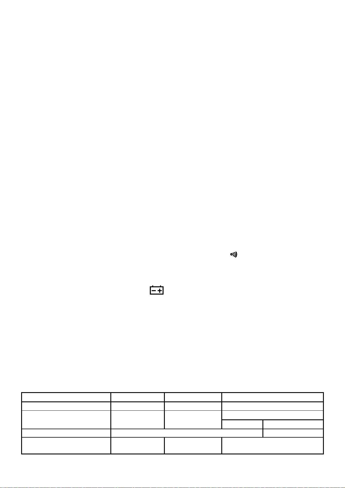
AC (alternating current)
DC (direct current)
Continuity buzzer
3. Maintenance
• Do not remove the back cover while a voltage is being applied. Only a qualified technician should handle repairs.
• Always disconnect the test leads from all current sources before opening the meter.
• Always place the function and range switches in the OFF position when the device is not in use.
• Remove the batteries to keep them from leaking if the device is to be stored for a prolonged period of time.
• Use a damp cloth and a mild detergent to clean the device. Never apply abrasives or solvents to the meter
4. Description
General
• This digital insulation tester is equipped with two alarm functions. A humming sound is produced every two
seconds to prevent damage from improper operation when the function or range switch is in the wrong position.
• Press the test button and the alarm system will produce a humming sound every two seconds. The high voltage
output indicator will flash red, warning the operator of the risk of electroshocks because of the high output voltage.
• The device is protected against overload and a low-battery indication is provided.
• The device also has a data-hold function.
• Two rotary switches are used to select the functions and ranges.
• The DVM52IT has a test button that can be locked. Releasing the test button automatically discharges the
capacitance of the device.
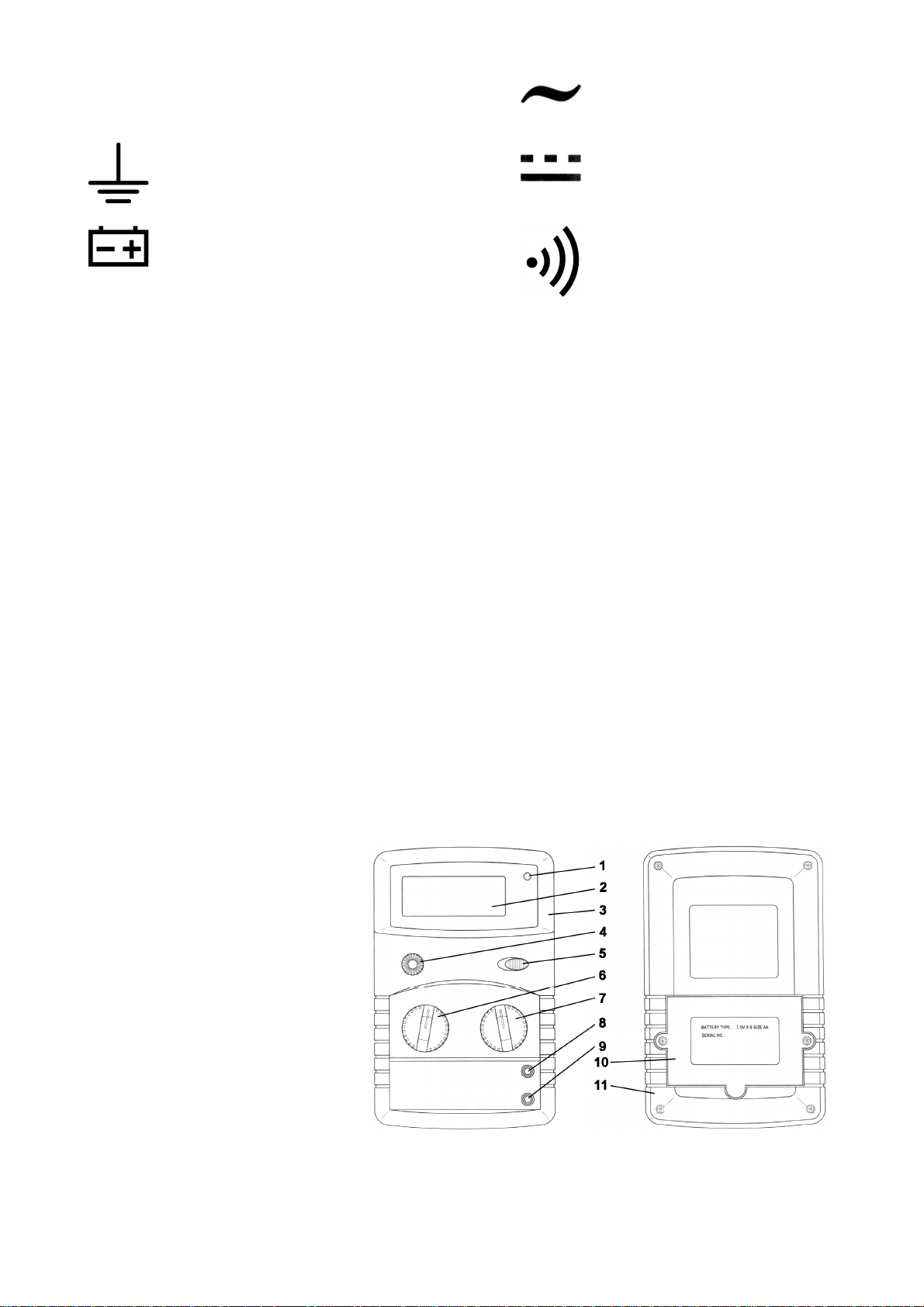
Front & Back Panel
1. High voltage output indicator
2. LCD display
3. Front panel
4. Test button
5. Data-hold switch
6. Function switch
7. Range switch
8. HIGH jack
9. LOW jack
10. Battery cover
11. Case
5. Specifications
Max. accuracy is achieved during a one-year period after calibration. Ideal circumstances require a temperature of 18
to 28°C (64 to 82°F) and a max. relative humidity of 75%.
DVM52IT VELLEMAN
Page 3
3
5.1 General Specifications
Max. voltage between terminals and earth 1000V dc or ac
Measuring Method Dual-slope integration A/D converter
Sampling Time ±0.4sec.
LCD Height 22mm
Max. Display 1999 points (3 ½ digits)
Polarity Indication ‘-‘ indicates negative polarity
Overrange Indication ‘1’ or ‘-1’ is displayed
Displayed Measuring Unit Unit of electrical capacity
Power Supply 6 AA-batteries of 1.5V (alkaline batteries are recommended)
Power Consumption ±5mA (100Vdc, 750Vac, 200Ω, )
±30mA (200MΩ, 250V)
±50mA (200MΩ/500V)
±100mA (2000MΩ/1000V)
Battery-Low Indication “ ”-symbol is displayed
Operating Temperature 0 to 40°C (32 to 104°F)
Operating Humidity < 85%RH
Storage Temperature -10 to +50°C (10 to 122°F)
Dimensions 192 x 122 x 55mm
Weight ± 545g (with batteries)
5.2 Electrical Specifications
5.2.1. Insulation Resistance
Range
200MΩΩΩΩ / 250V 200MΩΩΩΩ / 500V 2000MΩΩΩΩ / 1000V
Test Voltage 250Vdc ± 10% 500Vdc ± 10% 1000Vdc ± 10%
Measuring Ranges
0 ~200MΩ 0 ~200MΩ
0 ~2000MΩ
0 ~1000MΩ 1000 ~2000MΩ
Accuracy ± 3% rdg ± 5 digits ± 5% rdg ± 5 digits
Output Voltage on Open Circuit 250V ± 10% 500V ± 10% 1000V ± 10%
Min. Output Voltage
Test Current (approx.)
Output Short-Circuit Current
225V at 0.25MΩ 450V at 0.5MΩ 900V at 1MΩ
1mA at 0.25MΩ 1mA at 0.5MΩ 1mA at 1MΩ
≤ 2.5mA
5.2.2. AC Voltage
Range Resolution Accuracy
700V 1V ±1.2% of rdg + 5 digits
Input Impedance 10MΩ
Max. Input Voltage 700V rms AC or 1000V DC
Frequency Range 40 to 400Hz
Response average, calibrated in rms of a sine wave
DVM52IT VELLEMAN
Page 4
4
5.2.3. DC Voltage
Range Resolution Accuracy
1000V 1V ±0.8% of rdg + 3 digits
Input Impedance 10MΩ
Max. Input Voltage 1000V DC or 700V rms AC
5.2.4. Resistance
Range Resolution Accuracy
200Ω 0.1Ω
±1.0% of rdg + 3 digits
5.2.5. Continuity
Range Function
Built-in buzzer sounds if continuity exists (resistance < 50Ω)
Open Circuit Voltage ±2.5V
Overload Protection 250V DC or rms AC
6. Operating Instructions
6.1. Selecting the Appropriate Function and Range
When measuring AC voltage, DC voltage or resistance or when performing a continuity test, you should place the
function switch in the 200Ω , 700V~, 1000V position. Place the range switch in the 200Ω , 700V~ or
1000V position.
When measuring insulation resistance, you should place the function switch in the MANU., LOCK 1min., LOCK 2min.
or LOCK 4min. position. The device will produce a humming sound every 2 seconds and the display will show a
random reading if either the range or the function switch is in the wrong position.
6.2. Sonorous and Visual Alarm Signals
The device will emit a humming sound every two seconds and the red high voltage output indicator in the top righthand corner of the LCD will flash if the test button is pressed while the insulation range is selected.
6.3. Data-Hold Function
Simply toggle the hold switch to the right if you want to hold a particular value while measuring. The data-hold symbol
appears on the LCD. Slide the switch to the left again to leave the data-hold mode.
DVM52IT VELLEMAN
Page 5
5
6.4. Manual Operation and Using the Test Button
When measuring insulation, you can rotate the function switch to the “MANU.” position. The meter is now operated
manually. The measurement begins when you press the test button. For prolonged measurements it can be very
practical to lock the test button : just press the button and turn it anticlockwise. You can place the function switch in
the LOCK 1min., LOCK 2min. or LOCK 4min. position to perform measurements of the indicated duration. Simply
place the function switch in the MANU. position again if you want to interrupt your measurements before the 1, 2 or 4
minutes are up.
6.5. Preparing for Measurements
When the symbol is printed beside on of the jacks, this means that the indicated limit values must be respected in
order to protect the inner circuits from damage.
The low-battery sign indicates that the batteries should be replaced. This symbol is displayed when the battery
voltage drops below 7V.
6.6. Measuring Insulation Resistance
Insulation tests should only be conducted on deactivated circuits. Connect the DVM52IT and the
circuit in question with test leads and press the test button to execute the test.
1. Select the required test mode (MANU., LOCK 1min., LOCK 2min., LOCK 4min.) with the function switch.
2. Select the required range (200MΩ/250V, 200MΩ/500V, 2000MΩ/1000V) with the range selector.
3. Connect the black test lead with the LOW jack and the red test lead with the HIGH jack.
4. Connect the test leads with the circuit to be tested.
5. Press the test button. In the manual mode, you can press and then rotate the test button anticlockwise to lock it.
6. Read the measured value from the LCD.
Never touch the circuit under test during your measurements. Do not rotate the range switch while
the test button is in the depressed position.
When your measurements are completed you must release the test button before the test leads are
disconnected. This is because the system is charged up and must be allowed to discharge through
the tester’s internal discharge resistor.
6.7. Measuring AC Voltage
1. Connect the black test lead with the LOW jack and the red test lead with the HIGH jack.
2. Put the function switch in the 200Ω , 700V~ or 1000V position.
3. Put the range switch in the 700V~position.
4. Connect the test leads with the source or load to be tested.
5. Read the measured value form the LCD.
The symbol indicates that the limit values of 700V rms AC and 1000V DC have to be respected. It may be
possible to measure higher voltages, but this may destroy the inner circuit. Be careful to avoid electroshocks when
performing measurements.
DVM52IT VELLEMAN
Page 6
6
6.8. Measuring DC Voltage
1. Connect the black test lead with the LOW jack and the red test lead with the HIGH jack.
2. Put the function switch in the 200Ω , 1000V . or 700V~ position.
3. Put the range switch in the 1000V position.
4. Connect the test leads with the source or load to be tested.
5. Read the measured voltage and the polarity of the red lead connection from the LCD.
The symbol indicates that the limit values of 700V rms AC and 1000V DC have to be respected. It may be
possible to measure higher voltages, but this may destroy the inner circuit. Be careful to avoid electroshocks when
performing measurements.
6.9. Measuring Resistance
Disconnect the circuit to be tested and make sure that all capacitors are fully discharged before measuring the incircuit resistance.
1. Connect the black test lead with the LOW jack and the red test lead with the HIGH jack.
2. Put the function switch in the 200Ω , 1000V . or 700V~ position.
3. Place the range switch in the 200Ω position.
3. Connect the test leads with the resistance under measurement.
4. Read the value from the LCD.
REMARKS
• The LCD displays the overrange indication “1” if the measured value is too high for the range you are using.
Select a higher range.
• The overrange indication “1” is displayed when the input is not connected e.g. in case of an open circuit.
6.10. Continuity Test
1. Connect the black test lead with the LOW jack and the red test lead with the HIGH jack.
2. Put the function switch in the 200Ω , 1000V . or 700V~ position.
3. Place the range switch in the position.
4. Connect the test leads with two points of the circuit to be tested.
5. The built-in buzzer will sound if continuity exists (resistance < 50Ω).
7. Maintenance
7.1. Replacing the Batteries
Disconnect the test leads from the circuit to be tested before removing the battery cover. This is
necessary to avoid the risk of electroshocks.
1. The batteries need to be replaced when the sign appears on the LCD.
2. Open the battery cover with the included screwdriver.
3. Replace the old batteries with new ones.
4. Replace the battery cover.
DVM52IT VELLEMAN
Page 7
7
7.2. Replacing the Test leads
Only when you use the supplied test leads can we guarantee that you are complying fully with the safety standards. If
necessary, they should be replaced with test leads of the same model or with the same ratings. Electric ratings of the
test leads : 1000V 5A. Replace the test leads if the lead is exposed.
8. Accessories
• plastic case
• test leads (electric ratings 1000V / 5A)
• carrying bag for DVM52IT (without accessories)
• 6 x AA-battery of 1.5V
• manual
• screwdriver
For more info concerning this product, please visit our website www.velleman.eu.
The information in this manual is subject to change without prior notice.
DVM52IT – DIGITALE ISOLATIETESTER
1. Inleiding & veiligheidsvoorschriften
Aan alle ingezetenen van de Europese Unie
Belangrijke milieu-informatie betreffende dit product
Dit symbool op het toestel of de verpakking geeft aan dat, als het na zijn levenscyclus wordt weggeworpen,
dit toestel schade kan toebrengen aan het milieu.
Gooi dit toestel (en eventuele batterijen) niet bij het gewone huishoudelijke afval; het moet bij een
gespecialiseerd bedrijf terechtkomen voor recyclage.
U moet dit toestel naar uw verdeler of naar een lokaal recyclagepunt brengen.
Respecteer de plaatselijke milieuwetgeving.
Hebt u vragen, contacteer dan de plaatselijke autoriteiten inzake verwijdering.
Dank u voor uw aankoop! Lees de handleiding aandachtig voor u het toestel in gebruik neemt.
Dit toestel is ontworpen conform IEC 348 en IEC-1010 met betrekking tot de veiligheidsvoorschriften voor
elektronische meetinstrumenten met een overspanningscategorie (CAT II) en pollutie 2. De handleiding bevat een
aantal veiligheidsinstructies die naar de letter moeten worden uitgevoerd. Lees deze instructies voor u het toestel in
gebruik neemt!!
Zelfs bij een lage spanning of stroom kunnen zich dodelijke ongevallen voordoen. Het is zeer belangrijk om deze
veiligheidsvoorschriften te lezen voor u het toestel in gebruik neemt. Respecteer alle veiligheidsvoorschriften en alle
richtlijnen voor de bediening van dit toestel.
• De gebruiker moet zich beschermen tegen elektroshocks.
• Gebruik het toestel enkel op de manier en voor de toepassingen die worden beschreven in deze handleiding.
• Ga na of het toestel niet werd beschadigd tijdens het transport.
• De isolatie van de testsnoeren mag niet beschadigd zijn en/of de draad zelf mag niet blootliggen.
• U voldoet enkel aan de veiligheidsvereisten indien u het toestel gebruikt met de meegeleverde testsnoeren. Zo
nodig moet u ze vervangen door identieke snoeren of door testsnoeren met identieke elektrische specificaties. Alle
testsnoeren moeten in goede staat zijn.
• Overschrijd nooit de vermelde grenswaarden voor de verschillende meetbereiken.
• Raak nooit ongebruikte ingangsaansluitingen aan wanneer het toestel aangesloten is op een schakeling.
• Meet nooit spanningen tussen de ingangsbus en de aarde die 1000V overschrijden.
DVM52IT VELLEMAN
Page 8
8
• Wees uiterst voorzichtig wanneer u werkt met spanningen hoger dan 60VDC of 30Vrms AC. Houd uw vingers
achter de beschermende rand wanneer u het apparaat gebruikt.
• Sluit de snoeren niet aan op een spanningsbron terwijl de functieschakelaar is ingesteld op één van de volgende
modes : isolatieweerstand, weerstand of continuïteit.
• Voer nooit metingen uit op schakelingen die onder stroom staan.
• U moet alle testsnoeren loskoppelen van de schakeling die u wil testen vóór u een andere functie of bereik instelt.
• Bij defect moet u een geschoold technicus raadplegen.
• U mag de meter enkel gebruiken wanneer het achterpaneel goed dichtgeschroefd is.
• U mag het toestel niet gebruiken of opbergen in een omgeving die is blootgesteld aan rechtstreeks zonlicht, hoge
temperaturen of een hoge vochtigheidsgraad.
2. Symbolen
Belangrijke informatie m.b.t. de veiligheid, raadpleeg de handleiding!
Dubbele isolatie (Bescherming Klasse II)
Massa
Batterij bijna leeg
AC (wisselstroom)
DC (gelijkstroom)
Continuïteitsbuzzer
3. Onderhoud
• Verwijder het achterpaneel niet terwijl een spanning is aangesloten. Enkel een geschoolde technicus mag dit
toestel repareren.
• Ontkoppel de testsnoeren van alle stroombronnen voor u de behuizing opent.
• Plaats de functie- en bereikschakelaar in de OFF stand wanneer u het toestel niet gebruikt.
• Verwijder de batterij indien u het toestel gedurende lange tijd niet gebruikt. Zo beschermt u het toestel tegen
lekken.
• Veeg het toestel schoon met een klamme doek en milde detergent. Gebruik geen schurende middelen of
solventen.
4. Beschrijving
Algemeen
• Deze digitale isolatietester is uitgerust met twee alarmfuncties. Het toestel produceert een zoemgeluid om de
twee seconden om te voorkomen dat het toestel zou worden beschadigd door verkeerd gebruik wanneer de
functieschakelaar of de bereikschakelaar verkeerd staat ingesteld.
• Druk op de testknop en het alarmsysteem zal om de twee seconden een zoemgeluid produceren. De rode
indicator voor hoge uitgangsspanning knippert om de gebruiker te waarschuwen voor het gevaar voor
elektroshocks.
• Het toestel is beschermd tegen overbelasting en een batterij-laag aanduiding verschijnt op het scherm wanneer
de batterij moet worden vervangen.
• Het toestel is ook uitgerust met een data-hold functie.
• De functie en het bereik worden ingesteld met twee draaischakelaars.
• De DVM52IT heeft een testknop die kan worden vergrendeld. Bij het ontgrendelen van de testknop wordt de
capaciteit van de DVM52IT automatisch ontladen.
DVM52IT VELLEMAN
Page 9
9
Front- en achterpaneel (zie fig. blz. 2)
1. Indicator voor hoge uitgangsspanning 7. Bereikschakelaar
2. LCD display 8. HIGH jack
3. Frontpaneel 9. LOW jack
4. Testknop 10. Batterijdeksel
5. Data-hold schakelaar 11. Behuizing
6. Functieschakelaar
5. Specificaties
U kunt max. nauwkeurigheid verwachten tot 1 jaar na de ijking. De ideale werkomstandigheden vereisen een
temperatuur van 18 tot 28°C (64 tot 82°F) en een max. relatieve vochtigheidsgraad van 75%.
5.1 Algemene specificaties
Max. spanning tussen
ingangsaansluitingen en aarding 1000V dc of ac
Meetmethode Dual-slope integratie A/D converter
Bemonsteringsfrequentie ±0.4sec.
LCD hoogte 22mm
Max. uitlezing 1999 punten (3 ½ digits)
Polariteitsaanduiding ‘-‘ geeft negatieve polariteit aan
Buiten-bereik aanduiding ‘1’ of ‘-1’ wordt weergegeven
Weergegeven meeteenheid Eenheid van elektrische capaciteit
Voeding 6 x AA-batterij van 1.5V (alkalinebatterijen worden aanbevolen)
Verbruik ±5mA (100Vdc, 750Vac, 200Ω, )
±30mA (200MΩ, 250V)
±50mA (200MΩ/500V)
±100mA (2000MΩ/1000V)
Batterij-laag aanduiding “ ”-symbool verschijnt op de LCD
Werktemperatuur 0 tot 40°C (32 tot 104°F)
Relatieve vochtigheid < 85%RH
Opslagtemperatuur -10 tot +50°C (10 tot 122°F)
Afmetingen 192 x 122 x 55mm
Gewicht ± 545g (met batterij)
5.2 Elektrische specificaties
5.2.1. Isolatieweerstand
Bereik
200MΩΩΩΩ / 250V 200MΩΩΩΩ / 500V 2000MΩΩΩΩ / 1000V
Testspanning 250Vdc ± 10% 500Vdc ± 10% 1000Vdc ± 10%
Meetbereiken
0 ~200MΩ 0 ~200MΩ
0 ~1000MΩ 1000 ~2000MΩ
Nauwkeurigheid ± 3% uitlezing ± 5 digits ± 5% uitlzg ± 5 digits
Uitgangsspanning bij
250V ± 10% 500V ± 10% 1000V ± 10%
open schakeling
0 ~2000MΩ
DVM52IT VELLEMAN
Page 10
10
Min. uitgangsspanning
Teststroom (bij benadering)
Kortsluitstroom van de uitgang
225V bij 0.25MΩ 450V bij 0.5MΩ 900V bij 1MΩ
1mA bij 0.25MΩ 1mA bij 0.5MΩ 1mA bij 1MΩ
≤ 2.5mA
5.2.2. AC spanning
Bereik Resolutie Nauwkeurigheid
700V 1V ±1.2% of rdg + 5 digits
Ingangsimpedantie 10MΩ
Max. ingangsspanning 700V rms AC or 1000V DC
Frequentiebereik 40 to 400Hz
Respons gemiddeld, gekalibreerd in rms van een sinusgolf
5.2.3. DC spanning
Bereik Resolutie Nauwkeurigheid
1000V 1V ±0.8% van uitlzg + 3 digits
Ingangsimpedantie 10MΩ
Max. ingangsspanning 1000V DC of 700V rms AC
5.2.4. Weerstand
Bereik Resolutie Nauwkeurigheid
200Ω 0.1Ω
±1.0% of rdg + 3 digits
5.2.5. Continuïteit
Bereik Functie
Ingebouwde buzzer weerklinkt als er continuïteit is (weerstand < 50Ω)
Open-klemspanning ±2.5V
Bescherming tegen overbelasting 250V DC of rms AC
6. Bedieningsinstructies
6.1. Selecteer het juiste bereik en de juiste functie
Plaats de functieschakelaar in de 200Ω , 700V~, 1000V stand wanneer u AC spanning, DC spanning of
weerstand meet of wanneer u continuïteit test. Plaats de bereikschakelaar in de 200Ω , 700V~ of de 1000V
stand.
DVM52IT VELLEMAN
Page 11

11
Plaats de functieschakelaar in de MANU., LOCK 1min., LOCK 2min. of LOCK 4min. stand om isolatieweerstand te
meten. Het toestel produceert om de 2 seconden een zoemgeluid en op de display verschijnt een willekeurige
uitlezing indien de functie- of bereikschakelaar in de verkeerde stand staat.
6.2. Visuele en auditieve alarmsignalen
Het toestel produceert een zoemend geluid om de 2 seconden en de rode indicator voor hoge uitgangsspanning in
de rechterbovenhoek van de LCD begint te knipperen indien u de testknop indrukt terwijl het isolatiebereik is
geselecteerd.
6.3. Data-hold functie
Schuif de hold-schakelaar naar rechts indien u een bepaalde gemeten waarde wilt vasthouden. Het data-hold
symbool verschijnt nu op het scherm. Schuif de schakelaar weer naar links om de data-hold mode te verlaten.
6.4. Manuele bediening en gebruik van de testknop
Voor isolatiemetingen kunt u de functieschakelaar in de “MANU.” stand plaatsen zodat het toestel nu manueel kan
worden bediend. De meting begint wanneer u de testknop indrukt. Voor langdurige metingen is het heel handig om
de testknop te vergrendelen : druk de testknop in en draai hem in tegenwijzerzin. U kunt de functieschakelaar in de
LOCK 1min., LOCK 2min. of LOCK 4min. stand plaatsen om metingen uit te voeren gedurende 1, 2 of 4 minuten.
Plaats de functieschakelaar gewoon weer in de MANU. stand om de automatische metingen te onderbreken voor de
1, 2 of 4 minuten verstreken zijn.
6.5. Metingen voorbereiden
Wanneer het symbool naast één van de jacks staat, dan wil dit zeggen dat u de aangegeven grenswaarde moet
respecteren zodat de interne schakelingen niet worden beschadigd.
Het batterij-laag symbool geeft aan dat de batterij moet worden vervangen. Dit symbool verschijnt op de LCD
wanneer de batterijspanning onder de 7V daalt.
6.6. Isolatieweerstand meten
U mag enkel isolatietests uitvoeren op schakelingen die niet geactiveerd zijn. Verbind de DVM52IT
en de schakeling in kwestie met behulp van de meetsnoeren en druk op de testknop om de test uit
te voeren.
1. Selecteer de gewenste testmode (MANU., LOCK 1min., LOCK 2min., LOCK 4min.) met de functieschakelaar.
2. Selecteer het juiste bereik (200MΩ/250V, 200MΩ/500V, 2000MΩ/1000V) met de bereikschakelaar.
3. Verbind het zwarte meetsnoer met de LOW jack en het rode meetsnoer met de HIGH jack.
4. Verbind de meetsnoeren met de schakeling die u wilt testen.
5. Druk de testknop in. In de manuele mode kunt u deze knop vergrendelen : druk de knop in en draai hem in
tegenwijzerzin.
6. Lees de gemeten waarde af van de LCD.
DVM52IT VELLEMAN
Page 12

12
Tijdens de meting mag u nooit de schakeling aanraken die u aan het testen bent. Verdraai de
bereikschakelaar niet terwijl de testknop in de ingedrukte stand staat.
Na uw metingen moet u eerst de testknop ontgrendelen voor u de meetsnoeren losmaakt. Dit komt
omdat het systeem is opgeladen en moet kunnen ontladen via de interne ontladingsweerstand.
6.7. AC spanning meten
1. Verbind het zwarte meetsnoer met de LOW jack en het rode meetsnoer met de HIGH jack.
2. Plaats de functieschakelaar in de 200Ω , 700V~ of 1000V stand.
3. Plaats de bereikschakelaar in de 700V~stand.
4. Verbind de meetsnoeren met de bron of de belasting die u wilt testen.
5. Lees de gemeten waarde af van de LCD.
Het symbool geeft aan dat u de grenswaarden van 700V rms AC en 1000V DC moet respecteren. Het is
misschien wel mogelijk om hogere spanningen te meten, maar dit kan dan wel de interne schakeling vernielen. Wees
voorzichtig tijdens uw metingen zodat u elektroshocks kunt vermijden.
6.8. DC spanning meten
1. Verbind het zwarte meetsnoer met de LOW jack en het rode meetsnoer met de HIGH jack.
2. Plaats de functieschakelaar in de 200Ω , 1000V . of 700V~ stand.
3. Plaats de bereikschakelaar in de 1000V stand.
4. Verbind de meetsnoeren met de bron of de belasting die u wilt testen.
5. Lees de gemeten waarde en de polariteit van het rode meetsnoer af van de LCD.
Het symbool geeft aan dat u de grenswaarden van 700V rms AC en 1000V DC moet respecteren. Het is
misschien wel mogelijk om hogere spanningen te meten, maar dit kan dan wel de interne schakeling vernielen. Wees
voorzichtig tijdens uw metingen zodat u elektroshocks kunt vermijden.
6.9. Weerstandsmetingen
Zorg ervoor dat bij weerstandsmetingen geen spanning meer op de schakeling staat en dat alle condensatoren
volledig ontladen zijn.
1. Verbind het zwarte meetsnoer met de LOW jack en het rode meetsnoer met de HIGH jack.
2. Plaats de functieschakelaar in de 200Ω , 1000V . of 700V~ stand.
3. Plaats de bereikschakelaar in de 200Ω stand.
3. Verbind de meetsnoeren met de weerstand die u wilt testen.
4. Lees de gemeten waarde af van de LCD.
OPMERKINGEN
• De LCD geeft de buiten-bereik aanduiding “1” weer indien de gemeten waarde te hoog is voor het geselecteerde
bereik. Selecteer een hoger bereik.
• De buiten-bereik aanduiding “1” wordt weergegeven wanneer de ingang niet is aangesloten bv. in geval van een
open schakeling.
DVM52IT VELLEMAN
Page 13

13
6.10. Continuïteit testen
1. Verbind het zwarte meetsnoer met de LOW jack en het rode meetsnoer met de HIGH jack.
2. Plaats de functieschakelaar in de 200Ω , 1000V . of 700V~ stand.
3. Plaats de bereikschakelaar in de stand.
4. Verbind de meetsnoeren met twee punten van de schakeling die u wilt testen.
5. De ingebouwde buzzer gaat af indien er continuïteit is (weerstand < 50Ω).
7. Onderhoud
7.1. Batterijen vervangen
Ontkoppel de meetsnoeren van de schakeling die u wilt testen voor u het batterijdeksel verwijdert.
Dit is nodig om elektroshocks te vermijden.
1. U moet de batterijen vervangen wanneer het symbool op het scherm verschijnt.
2. Schroef het batterijdeksel los met de meegeleverde schroevendraaier.
3. Vervang de oude batterijen door nieuwe.
4. Breng het batterijdeksel weer aan en schroef het batterijvak dicht.
7.2. Meetsnoeren vervangen
U kunt enkel volledig voldoen aan de veiligheidsvereisten indien u de meegeleverde meetsnoeren gebruikt. Indien
nodig moet u ze vervangen door meetsnoeren van hetzelfde type of met dezelfde specificaties. Elektrische
specificaties van de meetsnoeren : 1000V 5A.
Vervang de meetsnoeren indien de kabel blootligt.
8. Accessoires
• plastieken draagkoffertje
• meetsnoeren (elektrische specificaties 1000V / 5A)
• draagtasje voor DVM52IT (zonder accessoires)
• 6 x AA-batterij van 1.5V
• handleiding
• schroevendraaier
Voor meer informatie omtrent dit product, zie www.velleman.eu.
De informatie in deze handleiding kan te allen tijde worden gewijzigd zonder voorafgaande kennisgeving.
DVM52IT – TESTEUR D’ISOLATION NUMÉRIQUE
1. Introduction & prescriptions de sécurité
Aux résidents de l'Union européenne
Des informations environnementales importantes concernant ce produit
Ce symbole sur l'appareil ou l'emballage indique que l’élimination d’un appareil en fin de vie peut polluer
l'environnement.
Ne pas éliminer un appareil électrique ou électronique (et des piles éventuelles) parmi les déchets
municipaux non sujets au tri sélectif ; une déchèterie traitera l’appareil en question.
Renvoyer les équipements usagés à votre fournisseur ou à un service de recyclage local.
Il convient de respecter la réglementation locale relative à la protection de l’environnement.
En cas de questions, contacter les autorités locales pour élimination.
DVM52IT VELLEMAN
Page 14

14
Nous vous remercions de votre achat ! Lisez la notice attentivement avant la mise en service de l’appareil.
Presc
ription de sécurité importante,
consultez le manuel
!
Cet appareil a été conçu en fonction de la norme IEC 348 et la norme IEC-1010 concernant les prescriptions de sécurité
pour les instruments de mesure électroniques avec une catégorie de surtension (CAT II) et pollution 2.. La notice contient
des instructions de sécurité qu’il faut respecter à la lettre. Lisez ces instructions avant d’utiliser l’appareil!!
Même une tension ou un courant d’intensité limitée peut avoir des conséquences fatales. Il est très important de lire
les instructions de sécurité avant la mise en service. Respectez toutes ces prescriptions de sécurité et les consignes
de la notice.
• L’utilisateur doit se protéger contre les électrochocs.
• Utilisez l’appareil de façon sûre et limitez-vous aux applications mentionnées dans la notice.
• Vérifiez si l’appareil n’a pas été endommagé pendant le transport.
• L’isolation des cordons de mesure ne peut pas être endommagée et/ou le câble proprement dit ne peut pas être
dénudé.
• Une conformité complète aux standards de sécurité ne peut être garantie qu'en cas d'utilisation des cordons de
mesure inclus. Si nécessaire, vous devez les remplacer par des cordons identiques ou par des cordons avec les
mêmes spécifications électroniques. Tous les cordons de mesure doivent être en bon état.
• Vous ne pouvez jamais excéder les valeurs limites des différentes plages de mesure.
• Evitez de toucher des bornes d’entrée non utilisées quand l'appareil est branché à un circuit.
• Ne mesurez aucune tension entre les bornes de connexion et la terre qui dépasse les 1000V.
• Soyez très prudent lorsque vous mesurez des tensions qui dépassent les 60VCC ou 30Vrms CA. Gardez vos
doigts derrière le protège-mains pendant vos mesures.
• Ne connectez aucune source de tension à l’appareil lorsque le sélecteur de fonction est réglé sur un des modes
suivants: résistance d’isolation, résistance ou continuité.
• N’effectuez aucune mesure sur des circuits mis sous tension.
• Déconnectez les cordons de mesure du circuit à tester avant de régler le sélecteur sur une autre fonction ou plage.
• Consultez un technicien qualifié en cas de panne.
• Vous pouvez uniquement utiliser l’appareil lorsque le panneau arrière est bien vissé.
• Il est interdit d’utiliser et de stocker l'appareil dans un environnement exposé aux rayons solaires, aux
températures élevées ou une humidité extrême.
2. Symboles
Double isolation (Protection Classe II)
Masse
Pile faible
AC (courant alternatif)
DC (courant continu)
Buzzer de continuité
3. Entretien
• Il est interdit d’enlever le panneau arrière pendant qu’une tension est connectée. Seulement un technicien qualifié
peut réparer cet appareil.
• Découplez les cordons de mesure de toute source de courant avant d’ouvrir le boîtier.
• Mettez le sélecteur de fonction et le sélecteur de plage dans la position OFF quand l'appareil n’est pas en service.
• Enlevez les piles en cas d’une longue période d’inactivité pour protéger l’appareil contre les fuites.
• Essuyez l’appareil avec un chiffon humide. Employez un détergent doux et évitez les solvants et les abrasifs.
DVM52IT VELLEMAN
Page 15

15
4. Description
Description générale
• Ce testeur d’isolation numérique est pourvu de deux fonctions d’alarme. L'appareil émet un signal sonore toutes
les deux secondes pour éviter l’endommagement de l’appareil lorsque le sélecteur de plage et que l’appareil
serait endommagé lorsque le sélecteur de fonction ou le sélecteur de plage n‘est pas dans la position correcte..
• Le système d’alarme émettra un signal sonore toutes les deux secondes quand vous pressez le bouton test.
L’indicateur rouge pour les hautes tensions de sortie commence à clignoter pour avertir l’utilisateur du danger
d’électrochocs.
• L’appareil est protégé contre les surcharges et une indication de pile faible est affichée quand il faut remplacer les
piles.
• L’appareil est également pourvu d’une fonction data hold.
• Sélectionnez la plage et la fonction désirées à l’aide des deux réglages rotatifs du panneau frontal.
• Le bouton test du DVM52IT peut être verrouillé. Le déverrouillage du bouton test donne lieu à la décharge
automatique de la capacité du mètre.
Panneau frontal et arrière (voir fig à la p. 2)
1. Indicateur de haute tension de sortie 7. Sélecteur de plage
2. Afficheur LCD 8. Jack HIGH
3. Panneau frontal 9. Jack LOW
4. Bouton test 10. Couvercle du compartiment des piles
5. Commutateur data hold 11. Boîtier
6. Sélecteur de fonction
5. Spécifications
L'appareil fonctionnera de façon optimale pendant les 12 mois après l'étalonnage. Les conditions d'utilisation idéales
exigent une température de 18 à 28°C (64 à 82°F) et une humidité relative max. de 75%.
5.1 Spécifications générales
Tension max. entre les
connexions de terre et l’entrée 1000V cc ou ca
Méthode de mesure Intégration dual-slope convertisseur A/D
Fréquence ‘échantillonnage ±0.4sec.
Hauteur de l’écran LCD 22mm
Affichage max. 1999 points (3 ½ digits)
Indication de polarité ‘-‘ indique une polarité négative
Indication hors-plage ‘1’ ou ‘-1’ est affiché
Unité de mesure affichée Unité de capacité électrique
Alimentation 6 x pile LR6 (AA) de 1.5V (les piles alcalines sont recommandées)
Consommation ±5mA (100Vcc, 750Vca, 200Ω, )
±30mA (200MΩ, 250V)
±50mA (200MΩ/500V)
±100mA (2000MΩ/1000V)
Indication pile faible Le symbole “
Température de travail 0 à 40°C (32 à 104°F)
DVM52IT VELLEMAN
” est affiché
Page 16

16
Humidité relative < 85%RH
Température de stockage -10 à +50°C (10 à 122°F)
Dimensions 192 x 122 x 55mm
Poids ± 545g (avec piles)
5.2 Spécifications électriques
5.2.1. Résistance d’isolation
Plage
200MΩΩΩΩ / 250V 200MΩΩΩΩ / 500V 2000MΩΩΩΩ / 1000V
Tension de test 250Vcc ± 10% 500Vcc ± 10% 1000Vcc ± 10%
Plages de mesure
0 ~200MΩ 0 ~200MΩ
0 ~1000MΩ 1000 ~2000MΩ
Précision ± 3% de l’aff. ± 5 digits ± 5% de l’aff. ± 5 digits
Tension de sortie
250V ± 10% 500V ± 10% 1000V ± 10%
lors de circuit ouvert
Tension de sortie min.
Courant de test (approx.)
Courant de court-circuit de la sortie
225V à 0.25MΩ 450V à 0.5MΩ 900V à 1MΩ
1mA à 0.25MΩ 1mA à 0.5MΩ 1mA à 1MΩ
≤ 2.5mA
5.2.2. Tension CA
Plage Résolution Précision
700V 1V ±1.2% de l’aff. + 5 digits
Impédance d’entrée 10MΩ
Tension d’entrée max. 700V rms CA ou 1000V CC
Plage de fréquence 40 à 400Hz
Réponse moyenne, calibrée en rms d’une sinusoïde
5.2.3. Tension CC
Plage Résolution Précision
1000V 1V ±0.8% de l’aff. + 3 digits
Impédance d’entrée 10MΩ
Tension d’entrée max. 1000V CC ou 700V rms CA
5.2.4. Résistance
Plage Résolution Précision
200Ω 0.1Ω
±1.0% de l’aff. + 3 digits
0 ~2000MΩ
DVM52IT VELLEMAN
Page 17

17
5.2.5. Continuité
Plage Fonction
Le buzzer incorporé retentit si continuité existe (résistance < 50Ω)
Tension à circuit ouvert ±2.5V
Protection contre les surcharges 250V CC ou rms CA
6. Instructions d’opération
6.1. Sélectionner la bonne plage et la bonne fonction
Mettez le sélecteur de fonction dans la position 200Ω , 700V~, 1000V pour vos tests de continuité et pour
mesurer des tensions CA et CC et des résistances. Placez le sélecteur de plage dans la position 200Ω , 700V~ ou
1000V .
Placez le sélecteur de fonction dans une des positions des suivantes pour mesurer la résistance d’isolation : MANU.,
LOCK 1min., LOCK 2min. ou LOCK 4min. L’appareil émettra un signal sonore toutes les deux secondes et une
valeur arbitraire sera affichée si le sélecteur de fonction ou le sélecteur de plage n’est pas dans la position correcte.
6.2. Signal d’alarme sonore et signal d’alarme visuel
L’appareil émet un signal sonore toutes les 2 secondes et l’indicateur rouge tension de sortie élevée dans le coin
supérieur droit de l’afficheur LCD commence à clignoter quand vous pressez le bouton test pendant un test
d’isolation.
6.3. Fonction data hold
Glissez le commutateur à droite pour tenir une valeur mesurée. Le symbole data-hold est apparaît sur l’écran.
Glissez le commutateur à gauche pour quitter le mode data hold.
6.4. Opération manuelle et emploi du bouton test
Placez le sélecteur de fonction dans la position “MANU.” pendant vos mesures d’isolation. Vous pouvez alors opérer
l’appareil manuellement. La mesure commence lorsque vous pressez le bouton test. Pour des mesures de longue
durée vous pouvez utiliser la fonction de verrouillage du bouton test : pressez-le en le tournant contre le sens des
aiguilles d’une montre. Placez le sélecteur de fonction dans la position LOCK 1min., LOCK 2min. ou LOCK 4min.
pour des mesures de 1, 2 ou 4 minutes. Retournez le sélecteur de fonction à la position MANU. s ivous voulez
arrêter les mesures avant la fin des 1, 2 ou 4 minutes.
6.5. Préparer des mesures
Le symbole à côté d’un des jacks sert à vous avertir qu’il faut respecter les valeurs limites afin de protéger les
circuits internes.
Le symbole pile faible
apparaît sur l’écran LCD lorsqu’il faut remplacer les piles, c.-à-d. quand la tension des
piles et inférieure à 7V.
DVM52IT VELLEMAN
Page 18

18
6.6. Mesurer la résistance d’isolation
Des tests d’isolation sont permis qu’avec des circuits non activés. Connectez le DVM52IT au circuit
en question à l’aide des cordons de mesure et pressez le bouton test pour effectuer le test.
1. Sélectionnez le mode de test désiré (MANU., LOCK 1min., LOCK 2min., LOCK 4min.) avec le sélecteur de
fonction.
2. Sélectionnez la plage correcte (200MΩ/250V, 200MΩ/500V, 2000MΩ/1000V) avec le sélecteur de plage.
3. Connectez le cordon de mesure noir avec le jack LOW et le cordon de mesure rouge avec le jack HIGH.
4. Connectez les cordons de mesure au circuit à tester.
5. Pressez le bouton test. Dans le mode manuel il est possible de verrouiller ce bouton : pressez le bouton et
tournez-le contre le sens des aiguilles d’une montre.
6. Lisez la valeur mesurée sur l’écran LCD.
Ne touchez jamais le circuit testé pendant le test. Ne changez pas de plage pendant que le bouton
test se trouve dans la position enfoncée.
Après vos mesures, il faut d’abord déverrouiller le bouton test avant de déconnecter les cordons de
mesure. Ceci est dû au fait que le système est chargé et doit avoir la possibilité de décharger via la
résistance de décharge interne de l’appareil.
6.7. Mesurer des tensions CA
1. Connectez le cordon de mesure noir au jack LOW et le cordon de mesure rouge avec le jack HIGH.
2. Placez le sélecteur de fonction dans la position 200Ω , 700V~ ou 1000V .
3. Mettez le sélecteur de plage dans la position 700V~.
4. Connectez les cordons de mesure à la source ou la charge à mesurer.
5. La valeur mesurée est affichée sur l’écran LCD.
Le symbole indique qu’il faut respecter les valeurs limites de 700V rms CA et 1000V CC. Il se peut qu’il soit
possible de mesurer des tensions plus élevées, mais vous risquez de détruire le circuit interne. Une bonne dose de
circonspection pendant vos mesures vous permettra d’éviter des électrochocs.
6.8. Mesurer des tensions CC
1. Connectez le cordon de mesure noir au jack LOW et le cordon de mesure rouge avec le jack HIGH.
2. Placez le sélecteur de fonction dans la position 200Ω , 1000V ou 700V~.
3. Mettez le sélecteur de plage dans la position 1000V .
4. Connectez les cordons de mesure à la source ou la charge à mesurer.
5. La valeur mesurée et la polarité du cordon de mesure rouge sont affichées sur l’écran LCD.
Le symbole indique qu’il faut respecter les valeurs limites de 700V rms CA et 1000V CC. Il se peut qu’il soit
possible de mesurer des tensions plus élevées, mais vous risquez de détruire le circuit interne. Une bonne dose de
circonspection pendant vos mesures vous permettra d’éviter des électrochocs.
6.9. Mesures de résistance
Déconnectez le circuit à tester et déchargez tous les condensateurs avant de tester la résistance dans le circuit.
1. Connectez le cordon de mesure noir au jack LOW et le cordon de mesure rouge avec le jack HIGH.
2. Placez le sélecteur de fonction dans la position 200Ω
DVM52IT VELLEMAN
, 1000V ou 700V~.
Page 19

19
3. Mettez le sélecteur de plage dans la position 200Ω.
3. Connectez les cordons de mesure à la résistance à tester.
4. La valeur mesurée est affichée sur l’écran LCD
REMARQUES
• L’indication hors-plage "1" est affichée si la valeur mesurée dépasse la valeur limite de la plage sélectionnée.
Sélectionnez une plage plus élevée.
• L’indication hors-plage "1" est affichée lorsque l’entrée n’est pas connectée p. ex. en cas de circuit couvert.
6.10. Test de continuité
1. Connectez le cordon de mesure noir au jack LOW et le cordon de mesure rouge avec le jack HIGH.
2. Placez le sélecteur de fonction dans la position 200Ω , 1000V ou 700V~.
3. Mettez le sélecteur de plage dans la position .
4. Connectez les cordons de mesure avec deux points du circuit à tester.
5. Le buzzer incorporé retentit s’il y a continuité (résistance < 50Ω).
7. Entretien
7.1. Remplacer les piles
Déconnectez les cordons de mesure du circuit à tester avant d’enlever le couvercle du compartiment
des piles. Ceci est nécessaire afin d‘éviter des électrochocs.
1. Remplacez les piles quand le symbole apparaît sur l’écran.
2. Dévissez le couvercle du compartiment des piles avec le tournevis inclus.
3. Insérez les nouvelles piles.
4. Replacez le couvercle et serrez les vis.
7.2. Remplacer les cordons de mesure
Vous devez utiliser les cordons de mesure inclus pour satisfaire aux prescriptions de sécurité. Si nécessaire, vous
devez les remplacer par des cordons du même type ou des cordons ayant les mêmes spécifications. Spécification
électrique des cordons de mesure : 1000V 5A.
Remplacez un cordon de mesure quand la gaine est endommagée, révélant le câble même.
8. Accessoires
• coffret en plastique
• cordons de mesure (spécifications électriques 1000V / 5A)
• sacoche pour le DVM52IT (sans accessoires)
• 6 x pile sLR6 (AA) de 1.5V
• notice
• tournevis
Pour plus d’information concernant cet article, visitez notre site web www.velleman.com.
Toutes les informations présentées dans cette notice peuvent être modifiées sans notification préalable.
DVM52IT VELLEMAN
Page 20

20
DVM52IT – COMPARADOR DE AISLAMIENTO
¡
Instrucciones importantes de
seguridad, consulte el manual!
Aislamiento doble (Protección CAT II)
DC (corriente continua / CC)
1. Introducción & disposiciones de seguridad
A los ciudadanos de la Unión Europea
Importantes informaciones sobre el medio ambiente concerniente a este producto
Este símbolo en este aparato o el embalaje indica que, si tira las muestras inservibles, podrían dañar el
medio ambiente.
No tire este aparato (ni las pilas, si las hubiera) en la basura doméstica; debe ir a una empresa
especializada en reciclaje. Devuelva este aparato a su distribuidor o a la unidad de reciclaje local.
Respete las leyes locales en relación con el medio ambiente.
Si tiene dudas, contacte con las autoridades locales para residuos.
¡Gracias por haber comprado el DVM52IT! Lea atentamente las instrucciones del manual antes de la puesta en
marcha.
El aparato cumple con las normas IEC 348 y IEC-1010 de acuerdo con las disposiciones de seguridad para equipos
electrónicos de medición con una categoría de sobretensión (CAT II) y una clasificación de contaminación de grado
2. Incluso tensiones o corrientes de intensidad limitada pueden causar lesiones graves. ¡Sea cuidadoso al operar el
multímetro y manténgalo en buen estado, respetando las disposiciones de seguridad! ¡Lea este manual en su
totalidad, antes de usar este comprobador!
• Protéjase contra las descargas eléctricas.
• Use el multímetro únicamente en las aplicaciones para las que ha sido diseñado siguiendo los procedimientos de
medición descritos en el manual.
• Verifique si el aparato ha sufrido algún daño en el transporte antes de la puesta en marcha.
• Asegúrese de que el aislamiento de las puntas de prueba no esté dañado y/o el cable mismo no esté expuesto.
• Use sólo el mismo tipo de puntas de prueba que fueron suministradas con su multímetro. Si es necesario,
reemplácelas por puntas de prueba idénticas o por puntas de prueba con especificaciones eléctricas idénticas.
Asegúrese del buen estado de las mismas.
• No exceda nunca los valores máximos de las diferentes gamas de medición mencionadas en este manual.
• Nunca toque terminales no utilizados cuando el multímetro está conectado a un circuito a prueba.
• Nunca mida tensiones entre los bornes de conexión y la masa de más de 1000V.
• Sea extremadamente cuidadoso al medir tensiones de más de 60VDC o 30Vrms AC. Guarde sus dedos detrás
de los topes protectores durante las mediciones.
• No conecte ninguna fuente de tensión al aparato si el selector de función se encuentra en uno de los siguientes
modos: resistencia de aislamiento, resistencia o continuidad.
• No efectúe mediciones en circuitos bajo tensión.
• Desconecte las puntas de prueba del circuito analizado antes de seleccionar otra función u otra gama.
• Contacte con un técnico cualificado en caso de duda.
• Nunca realice mediciones cuando el panel posterior del multímetro no esté cerrado.
• No exponga el instrumento a la luz solar directa, temperaturas extremas ni humedad.
2. Símbolos
DVM52IT VELLEMAN
Page 21

21
Pil
a descargada
Buzzer : avisador acústico de
Masa
continuidad
3. Mantenimiento
• No abra la tapa posterior si está conectado a una tensión. Las reparaciones deben ser realizadas por personal
especializado.
• Desconecte las puntas de prueba de toda fuente de alimentación antes de abrir la caja.
• Coloque el selector de función y el selector de rango en la posición OFF si no está usando el aparato.
• Para proteger el multímetro contra fugas, quite las pilas si no va a usarlo durante un largo período de tiempo.
• Limpie el comprobador de aislamiento con un paño húmedo. Evite el uso de productos químicos abrasivos,
disolventes o detergentes.
4. Descripción
Descripción general
• Este comprobador de aislamiento digital está equipado con dos funciones de alarma. El aparato emite una señal
sonora cada dos segundos para evitar daños cuando el selector de función o el selector de rango no está en la
posición correcta.
• El sistema de alarma emite una señal sonora cada dos segundos pulsando el botón de prueba. El indicador rojo
para las elevadas tensiones de salida empiezan a parpadear para avisar al usuario del peligro de descargas
eléctricas.
• El comprobador está protegido contra las sobrecargas y se visualiza una indicación de pila descargada si es
necesario reemplazar las pilas.
• El comprobador también está equipado con una función data hold.
• Seleccione el rango y la función deseados con dos ajustes giratorios del panel frontal.
• Es posible cerrar el botón de prueba del DVM52IT. Abrir el botón de prueba causa la descarga automática de la
capacidad del dispositivo.
Panel frontal y posterior (véase fig p. 2)
1. Indicador de alta tensión de salida 7. Selector de rango
2. Pantalla LCD 8. Jack HIGH
3. Panel frontal 9. Jack LOW
4. Botón de prueba 10. Tapa del compartimiento de pilas
5. Conmutador data hold 11. Caja
6. Selector de función
5. Especificaciones
Puede esperar una exactidud optima durante 1 año después de la calibración. Las condiciones de funcionamiento
ideales exigen una temperatura de 18 a 28°C (de 64 a 82°F) y un grado de humedad relativa máx. de 75%.
5.1 Especificaciones generales
Tensión máx. entre las
Conexiones de tierra y la entrada 1000V cc o ca
Método de medición convertidor A/D integración dual-slope
DVM52IT VELLEMAN
Page 22

22
Frecuencia de muestreo ±0.4seg.
Altura de la pantalla LCD 22mm
Display máx. 1999 puntos (3 ½ dígitos)
Indicador de polaridad aparece “-“ si hay polaridad negativa
Indicador de sobre rango aparece ‘1’ o ‘-1’
Unidad de medición visualizada unidad de capacidad eléctrica
Alimentación 6 x pila LR6 (AA) de 1.5V (se recomiendan las pilas alcalinas)
Consumo ± 5mA (100Vcc, 750Vca, 200Ω, )
± 30mA (200MΩ, 250V)
± 50mA (200MΩ/500V)
± 100mA (2000MΩ/1000V)
Indicador de batería baja aparece el símbolo “ ”
Temperatura de funcionamiento de 0 a 40°C (de 32 a 104°F)
Humedad relativa < 85%RH
Temperatura de almacenamiento de -10 a +50°C (de 10 a 122°F)
Dimensiones 192 x 122 x 55mm
Peso ± 545g (con pilas)
5.2 Especificaciones eléctricas
5.2.1. Resistencia de aislamiento
Rango
200MΩΩΩΩ / 250V 200MΩΩΩΩ / 500V 2000MΩΩΩΩ / 1000V
Tensión de prueba 250Vcc ± 10% 500Vcc ± 10% 1000Vcc ± 10%
Rango de medida
0 ~200MΩ 0 ~200MΩ
0 ~2000MΩ
0 ~1000MΩ 1000 ~2000MΩ
Precisión ± 3% lectura ± 5 dígitos ± 5% lectura ± 5
dígitos
Tensión de salida
250V ± 10% 500V ± 10% 1000V ± 10%
en circuito abierto
Tensión de salida mín. de 225V a
de 450V a 0.5MΩ de 900V a 1MΩ
0.25MΩ
Corriente de prueba (aprox.) de 1mA a
de 1mA a 0.5MΩ de 1mA a 1MΩ
0.25MΩ
Corriente de cortocircuito de la
≤ 2.5mA
salida
5.2.2. Tensión CA
Rango Resolución Precisión
700V 1V ±±1.2% lectura + 5 dígitos
Impedancia de entrada 10MΩ
Tensión de entrada máx. 700V rms CA o 1000V CC
Rango de frecuencia de 40 a 400Hz
Respuesta respuesta media, calibración en rms de una onda sinusoidal
DVM52IT VELLEMAN
Page 23

23
5.2.3. Tensión CC
Rango Resolución Precisión
1000V 1V ±0.8% lectura + 3 dígitos
Impedancia de entrada 10MΩ
Tensión de entrada máx. 1000V CC o 700V rms CA
5.2.4. Resistencia
Rango Resolución Precisión
200Ω 0.1Ω
±1.0% lectura + 3 dígitos
5.2.5. Continuidad
Rango Función
El zumbador (incorporado) suena si hay continuidad (resistencia < 50Ω)
Tensión en circuito abierto ±2.5V
Protección de sobrecarga 250V CC o rms CA
6. Instrucciones de operación
6.1. Seleccionar el buen rango y la buena función
Coloque el selector de función en la posición 200Ω , 700V~, 1000V para las pruebas de continuidad y para
medir tensiones CA y CC y la resistencia. Coloque el selector de rango en la posición 200Ω , 700V~ o 1000V .
Coloque el selector de función en una de las siguientes posiciones para medir la resistencia de aislamiento: MANU.,
LOCK 1min., LOCK 2min. o LOCK 4min. El aparato emite una señal sonora cada dos segundos y se visualiza un
valor arbitrario si el selector de función o el selector de rango no están en la posición correcta.
6.2. Señal de alarma audible y señal de alarma visual
El aparato emite una señal sonora cada dos segundos y el indicador rojo de tensión de salida elevada en la esquina
superior derecha de la pantalla LCD empieza a parpadear si pulsa el botón de prueba durante una prueba de
aislamiento.
6.3. Función data hold
Deslice el conmutador a la derecha para ‘congelar’ un valor medido. El símbolo data-hold aparece en la pantalla.
Deslice el conmutador a la izquierda para salir del modo data hold.
DVM52IT VELLEMAN
Page 24

24
6.4. Operación manual y uso del botón de prueba
Coloque el selector de función en la posición “MANU.” durante las mediciones de aislamiento. Ahora, puede manejar
el aparato manualmente. Empiece la medición pulsando el botón de prueba. Para mediciones de larga duración use
la función de bloqueo del botón de prueba: pulse este botón girándolo en sentido contrario al de las agujas del reloj.
Coloque el selector de función en la posición LOCK 1min., LOCK 2min. o LOCK 4min. para mediciones de 1, 2 ó 4
minutos. Vuelva a colocar el selector de función en la posición MANU. si quiere parar las mediciones antes el final
de 1, 2 ó 4 minutos.
6.5. Preparar las mediciones
El símbolo al lado de uno de los jacks indica que se deben respetar los valores límites a fin de proteger los
circuitos internos.
Si aparece el símbolo en la pantalla LCD, reemplace las pilas, es decir, si la tensión de la pila < 7V.
6.6. Medir la resistencia de aislamiento
Sólo están permitidas pruebas de aislamiento con circuitos no activados. Conecte el DVM52IT al
circuito en cuestión mediante las puntas de prueba y pulse el botón de prueba para hacer la prueba.
1. Seleccione el modo de prueba deseado (MANU., LOCK 1min., LOCK 2min., LOCK 4min.) con el selector de
función.
2. Seleccione el rango correcto (200MΩ/250V, 200MΩ/500V, 2000MΩ/1000V) con el selector de rango.
3. Conecte la punta de prueba negra al jack LOW y la punta de prueba roja al jack HIGH.
4. Conecte las puntas de prueba al circuito que Ud. desea probar.
5. Pulse el botón de prueba. En el modo manual es posible bloquear este botón : pulse el botón y gírelo en sentido
contrario al de las agujas del reloj.
6. El valor medido aparece en la pantalla LCD.
Nunca toque el circuito a prueba durante la prueba. No cambie el rango mientras que el botón de
prueba esté en la posición pulsada.
Después de las mediciones, desbloquee el botón de prueba antes de desconectar las puntas de
prueba. Esto se debe al hecho de que el sistema está cargado y debe tener la posibilidad de
descargar mediante la resistencia de descarga interna del aparato.
6.7. Medir tensiones CA
1. Conecte la punta de prueba negra al jack LOW y la punta de prueba roja al jack HIGH.
2. Coloque el selector de función en la posición 200Ω , 700V~ o 1000V .
3. Coloque el selector de rango en la posición 700V~.
4. Conecte las puntas de prueba a la fuente o la carga que Ud. desea probar.
5. El valor medido aparece en la pantalla LCD.
El símbolo indica que se deben respetar los valores límites de 700V rms CA y 1000V CC. Es posible medir
tensiones más elevadas, pero esto podría destruir el circuito interno. Sea cuidadoso durante las mediciones a fin de
evitar el riesgo de sufrir un choque eléctrico.
DVM52IT VELLEMAN
Page 25

25
6.8. Medir tensiones CC
1. Conecte la punta de prueba negra al jack LOW y la punta de prueba roja al jack HIGH.
2. Coloque el selector de función en la posición 200Ω , 1000V o 700V~.
3. Coloque el selector de rango en la posición 1000V .
4. Conecte las puntas de prueba a la fuente o a la carga que Ud. desea probar.
5. El valor medido aparece en la pantalla LCD. Se indica también la polaridad de la punta de prueba roja.
El símbolo indica que se deben respetar los valores límites de 700V rms CA y 1000V CC. Es posible medir
tensiones más elevadas, pero esto podría destruir el circuito interno. Sea cuidadoso durante las mediciones a fin de
evitar el riesgo de sufrir un choque eléctrico.
6.9. Medir la resistencia
Desconecte el circuito a prueba y descargue todos los condensadores antes de probar la resistencia en el circuito.
1. Conecte la punta de prueba negra al jack LOW y la punta de prueba roja al jack HIGH.
2. Coloque el selector de función en la posición 200Ω , 1000V o 700V~.
3. Coloque el selector de rango en la posición
200Ω.
3. Conecte las puntas de prueba a la resistencia que Ud. desea probar.
4. El valor medido aparece en la pantalla LCD
OBSERVACIONES
• Seleccione un rango superior si la indicación sobre rango “1” aparece en la pantalla.
• Aparece la indicación “1” en la pantalla si la entrada no está conectada p. ej. en caso de circuito abierto.
6.10. Prueba de continuidad
1. Conecte la punta de prueba negra al jack LOW y la punta de prueba roja al jack HIGH.
2. Coloque el selector de función en la posición 200Ω , 1000V o 700V~.
3. Coloque el selector de rango en la posición .
4. Conecte las puntas de prueba a dos puntas del circuito que quiere probar.
5. El zumbador incorporado suena si hay continuidad (resistencia < 50Ω).
7. Mantenimiento
7.1. Reemplazar la pila
Desconecte las puntas de prueba antes de abrir la caja o el compartimiento de pilas para evitar
choques eléctricos.
1. Reemplace la batería si aparece el símbolo en la pantalla.
2. Desatornille la tapa del compartimiento de pilas con el destornillador incluido.
3. Introduzca las nuevas pilas.
4. Cierre el compartimiento de pilas.
7.2. Reemplazar las puntas de prueba
Sólo use el mismo tipo de puntas de prueba que fueron suministradas con su multímetro. Si es necesario,
reemplácelas por puntas de prueba idénticas o por puntas de prueba con especificaciones eléctricas idénticas.
Asegúrese del buen estado de las mismas. Especificaciones eléctricas de las puntas de prueba: 1000V 5A.
Reemplace las puntas de prueba si el cable está expuesto.
DVM52IT VELLEMAN
Page 26

26
8. Accesorios
• maletín de plástico
• puntas de prueba (especificaciones eléctricas 1000V / 5A)
• funda de transporte para el DVM52IT (sin accesorios)
• 6 x pila LR6 (AA) de 1.5V
•
manual del usuario
•
destornillador
Para más información sobre este producto, visite nuestra página web www.velleman.eu.
Se pueden modificar las especificaciones y el contenido de este manual sin previo aviso.
DVM52IT – DIGITALER ISOLATIONSTESTER
1. Einführung & Sicherheitshinweise
An alle Einwohner der Europäischen Union
Wichtige Umweltinformationen über dieses Produkt
Dieses Symbol auf dem Produkt oder der Verpackung zeigt an, dass die Entsorgung dieses Produktes nach
seinem Lebenszyklus der Umwelt Schaden zufügen kann.
Entsorgen Sie die Einheit (oder verwendeten Batterien) nicht als unsortiertes Hausmüll; die Einheit oder
verwendeten Batterien müssen von einer spezialisierten Firma zwecks Recycling entsorgt werden.
Diese Einheit muss an den Händler oder ein örtliches Recycling-Unternehmen retourniert werden.
Respektieren Sie die örtlichen Umweltvorschriften.
Falls Zweifel bestehen, wenden Sie sich für Entsorgungsrichtlinien an Ihre örtliche Behörde.
Wir bedanken uns für den Kauf des DVM52IT! Lesen Sie diese Bedienungsanleitung vor Inbetriebnahme sorgfältig
durch.
Der DVM52IT wurde gemäß der IEC 348 und IEC-1010-Norm gebaut. Diese Norm bezieht sich auf elektronische
Messgeräte, die zur Überspannungskategorie (CAT II) und Verschmutzungsgrad 2 gehören.
Sogar niedrige Spannung oder niedriger Strom könnten Verletzungen verursachen. Um einen gefahrlosen Betrieb
sicherzustellen und Ihr Isolationstester leistungsfähig zu halten, müssen Sie genau alle Sicherheitshinweise und
Warnvermerke, die in dieser Bedienungsanleitung enthalten sind, beachten!!.
• Schutzen Sie sich vor elektrischen Schlägen.
• Verwenden Sie das Gerät nur auf die Weise und für die Anwendungen, die in der Anleitung beschrieben werden.
• Kontrollieren Sie, ob das Gerät während des Transports beschädigt wurde.
• Stellen Sie sicher, dass die Messleitungen und/oder das Kabel nicht beschädigt sind.
• Sie entsprechen allen Sicherheitshinweisen nur dann, wenn Sie zum Messen nur die Messleitungen verwenden,
welche dem Messgerät beiliegen. Wenn nötig, müssen Sie sie durch identische Messleitungen ersetzen.
• Überschreiten Sie für die verschiedenen Messbereiche nie die erwähnten Maximalwerte.
• Berühren Sie die freien Eingangsbuchsen nicht, wenn die Schaltungen nicht stromlos geschaltet worden sind.
• Messen Sie nie Spannungen, die 1000VDC zwischen der Eingangsbuchse und der Erde überschreiten.
• Seien Sie besonders vorsichtig wenn Sie mit Spannungen über 60VDC oder 30VAC rms arbeiten. Halten Sie die
Finger während Ihrer Messungen immer hinten den Prüfspitzen.
• Verbinden Sie die Messleitungen nie mit einer Spannungsquelle wenn der Funktionsschalter sich im
nachfolgenden Modus befindet: Isolationswiderstand, Widerstand oder Durchgangsprüfung.
• Führen Sie nie Messungen durch auf Schaltungen die unter Strom stehen.
• Trennen Sie die Messleitungen von der zu messenden Schaltung, ehe Sie den Funktionsschalter auf eine
andere Funktion oder einen anderen Bereich verstellen.
• Ziehen Sie bei Beschädigungen eine Fachkraft zu Rate.
DVM52IT VELLEMAN
Page 27

27
• Verwenden Sie das Messgerät erst dann, wenn das Gehäuse sicher geschlossen und verschraubt ist.
Wichtige Information in Beziehung auf die Sicherheit. Lesen Sie die Bedienungsanleitung !
Doppelte Isolierung (
Schutzklasse
II)
Lo-Bat-Anzeige
AC (
Wechselstrom
)
DC (Gleichstrom)
akustische Durchgangsprüfung
• Verwenden und bewahren Sie das Multimeter in normalen Umgebungsbedingungen auf. Setzen Sie es keinem
direkten Sonnenlicht, keinen extremen Temperaturen oder keiner Feuchtigkeit aus.
2. Symbole
Erdung
3. Wartung
• Trennen Sie Ihr Messgerät vom Messkreis. Nur Fachleute dürfen den DVM52IT reparieren.
• Trennen Sie die Messleitungen von allen Spannungsquellen, ehe das Gehäuse zu öffnen.
• Stellen Sie den Funktions- und Bereichsschalter auf OFF wenn Sie das Gerät nicht verwenden.
• Entfernen Sie die Batterie wenn Sie das Multimeter längere Zeit nicht verwenden. Die Batterien könnten
korrodieren und so Ihr Gerät zerstören.
• Nehmen Sie zur Reinigung des Gerätes ein feuchtes Reinigungstuch. Benutzen Sie auf keinen Fall Scheuer-
oder Lösungsmittel.
4. Beschreibung
Allgemein
• Dieser digitale Isolationstester verfügt über zwei Alarmfunktionen. Das Gerät produziert jede zwei Sekunden
einen Summton um zu verhindern, dass das Gerät durch falsche Anwendung beschädigt wird, wenn der
Funktionsschalter oder Bereichsschalter falsch eingestellt wird.
• Drücken Sie die Test-Taste und das Alarmsystem wird jede zwei Sekunden einen Summton produzieren. Die rote
Anzeige für hohe Ausgangsspannung blinkt um den Benutzer vor Gefahr vor elektrischen Schlägen warnen.
• Das Gerät hat überlastschutz und es erscheint eine Lo-Bat-Anzeige im Display wenn Sie einen Batteriewechsel
durchführen müssen.
• Der DVM52IT verfügt auch über eine Data-Hold-Funktion.
• Die Funktion und der Bereich werden mit zwei Drehschaltern eingestellt.
• Der DVM52IT hat eine Test-Taste, die verriegelt werden kann. Beim Lösen der Verriegelung der Test-Taste wird
die Kapazität des DVM52IT automatisch entladen.
DVM52IT VELLEMAN
Page 28

28
Frontplatte und Rückseite (siehe Abb. S. 2)
1. Anzeige für hohe Ausgangsspannung 7. Bereichsschalter
2. LCD-Display 8. HIGH-Buchse
3. Frontplatte 9. LOW-Buchse
4. Test-Taste 10. Batteriedeckel
5. Data-Hold-Schalter 11. Gehäuse
6. Funktionsschalter
5. Technische Daten
Bis ein Jahr nach der Kalibrierung dürfen Sie eine optimale Genauigkeit erwarten. Die idealen Wetterverhältnisse sind eine
Temperatur von 18 bis 28°C (64 bis 82°F) mit relativem Feuchtigkeitsgrad von max. 75%.
5.1 Allgemeine technische Daten
Max. Spannung zwischen
Eingangsanschlüssen und Erdung 1000V dc oder ac
Messverfahren Dual-Slope-Integration A/D Umwandler
Abtastzeit ±0.4Sek.
LCD Höhe 22mm
Max. Display 1999 Punkte (3 ½ Digits)
Polaritätsanzeige ‘-‘ erscheint bei negativer Polarität
Außenbereichsanzeige ‘1’ oder ‘-1’ erscheint
Anzeige Messeinheit Einheit von elektrischer Kapazität
Spannungsversorgung 6 x AA-Batterie, 1.5V (Alkalinebatterien werden empfohlen)
Verbrauch ±5mA (100Vdc, 750Vac, 200Ω, )
±30mA (200MΩ, 250V)
±50mA (200MΩ/500V)
±100mA (2000MΩ/1000V)
Lo-Bat-Anzeige “ ”-Symbol erscheint im Display
Arbeitstemperatur 0 bis 40°C (32 bis 104°F)
relativer Feuchtigkeitsgrad < 85%RH
Lagertemperatur -10 bis +50°C (10 bis 122°F)
Abmessungen 192 x 122 x 55mm
Gewicht ± 545g (mit Batterie)
5.2 Elektrische Daten
5.2.1. Isolationswiderstand
Bereich
200MΩΩΩΩ / 250V 200MΩΩΩΩ / 500V 2000MΩΩΩΩ / 1000V
Testspannung 250Vdc ± 10% 500Vdc ± 10% 1000Vdc ± 10%
Messbereiche
0 ~200MΩ 0 ~200MΩ
0 ~1000MΩ 1000 ~2000MΩ
Genauigkeit ± 3% ± 5 Digits ± 5% ± 5 Digits
Ausgangsspannung bei
250V ± 10% 500V ± 10% 1000V ± 10%
offener Schaltung
0 ~2000MΩ
DVM52IT VELLEMAN
Page 29

29
Min. Ausgangsspannung
Teststrom (annähernd)
Kurzschlussstrom des Ausgangs
225V bei 0.25MΩ 450V bei 0.5MΩ 900V bei 1MΩ
1mA bei 0.25MΩ 1mA bei 0.5MΩ 1mA bei 1MΩ
≤ 2.5mA
5.2.2. AC-Spannung
Bereich Auflösung Genauigkeit
700V 1V ±1.2% + 5 Digits
Eingangsimpedanz 10MΩ
Max. Eingangsspannung 700V rms AC oder 1000V DC
Frequenzbereich 40 bis 400Hz
Respons durchschnittlich, Kalibrierung in rms der Sinuswelle
5.2.3. DC-Spannung
Bereich Auflösung Genauigkeit
1000V 1V ±0.8% + 3 Digits
Eingangsimpedanz 10MΩ
Max. Eingangsspannung 1000V DC oder 700V rms AC
5.2.4. Widerstand
Bereich Auflösung Genauigkeit
200Ω 0.1Ω
±1.0% + 3 Digits
5.2.5. Durchgang
Bereich Funktion
Bei Durchgang ertönt ein akustisches Warnsignal (Widerstand < 50Ω)
Leerlaufspannung ±2.5V
Überlastschutz 250V DC oder rms AC
6. Bedienungsanleitung
6.1. Den richtigen Bereich und die richtige Funktion wählen
Stellen Sie den Funktionsschalter auf 200Ω , 700V~, 1000V wenn Sie AC -Spannung, DC-Spannung oder
Widerstand messen oder wenn Sie den Durchgang prüfen. Stellen Sie den Bereichsschalter auf 200Ω , 700V~
oder 1000V .
DVM52IT VELLEMAN
Page 30

30
Stellen Sie den Funktionsschalter auf MANU., LOCK 1min., LOCK 2min. oder LOCK 4min. um den
Isolationswiderstand zu messen. Es ertönt jede 2 Sekunden einen Summton und im Display erscheint eine beliebige
Anzeige wenn Funktions- oder Bereichsschalter in den falschen Stand stehen.
6.2. Visuelle und auditive Alarmsignale
Es ertönt jede 2 Sekunden einen Summton und die rote Anzeige für hohe Ausgangsspannung in der oberen rechten
Ecke vom LCD fängt an zu blinken wenn Sie die Test-Taste drücken während der Isolationsbereich gewählt ist.
6.3. Data-Hold-Funktion
Schieben Sie den Hold-Schalter nach rechts wenn Sie einen bestimmten Messwert festhalten möchten. Das DataHold-Symbol erscheint jetzt im Display. Schieben Sie den Schalter wieder nach links um den Data-Hold-Modus zu
verlassen.
6.4. Manuelle Bedienung und Gebrauch der Test-Taste
Stellen Sie den Funktionsschalter auf “MANU.” für Isolationsmessungen damit das Gerät manuell bedient werden
kann. Die Messung fängt an wenn Sie die Test-Taste drücken. Für längere Messungen ist es sehr handlich um die
Test-Taste zu verriegeln : drücken Sie die Test-Taste und drehen Sie sie gegen den Uhrzeigersinn. Sie können den
Funktionsschalter auf LOCK 1min., LOCK 2min. oder LOCK 4min. stellen um Messungen während 1, 2 oder 4
Minuten durchzuführen. Stellen Sie den Funktionsschalter einfach wieder auf MANU. um die automatischen
Messungen zu unterbrechen ehe die 1, 2 oder 4 Minuten ablaufen.
6.5. Messungen durchführen
Wenn das -Symbol neben einer der Buchsen steht, bedeutet das, dass Sie den angegebenen Grenzwert
respektieren müssen, so dass die internen Schaltungen nicht beschädigt werden.
Das Symbol erscheint im Display wenn die Batteriespannung unter 7V senkt. Ersetzen Sie die Batterie.
6.6. Isolationswiderstand messen
Führen Sie nur Isolationsprüfungen durch auf Schaltungen die nicht aktiviert sind. Verbinden Sie den
DVM52IT und die bewusste Schaltung mit den Messleitungen und drücken Sie die Test-Taste um
den Test durchzuführen.
1. Wählen Sie den gewünschten Test-Modus (MANU., LOCK 1min., LOCK 2min., LOCK 4min.) mit den
Funktionsschalter.
2. Wählen Sie den richtigen Bereich (200MΩ/250V, 200MΩ/500V, 2000MΩ/1000V) mit dem Bereichsschalter.
3. Verbinden Sie die schwarze Messleitung mit der LOW-Buchse und die rote Messleitung mit der HIGH-Buchse.
4. Verbinden Sie die Messleitungen mit der zu prüfenden Schaltung.
5. Drücken Sie die Test-Taste. Im manuellen Modus können Sie diese Test-Taste verriegeln : drücken Sie die Taste
und drehen Sie sie gegen den Uhrzeigersinn.
6. Lesen Sie den Messwert vom LCD-Display ab.
DVM52IT VELLEMAN
Page 31

31
Berühren Sie während der Messungen nie die Schaltung. Drehen Sie nicht am Bereichsschalter
während die Test-Taste sich in gedrückter Position befindet.
Lösen Sie nach den Messungen zuerst die Verriegelung der Test-Taste ehe Sie Messleitungen
trennen. Dies kommt weil das System aufgeladen ist und die Möglichkeit haben muss, über den
internen Entladungswiderstand zu entladen.
6.7. AC-Spannung messen
1. Verbinden Sie die schwarze Messleitung mit der LOW-Buchse und die rote Messleitung mit der HIGH-Buchse.
2. Stellen Sie den Funktionsschalter auf 200Ω , 700V~ oder 1000V .
3. Stellen Sie den Bereichsschalter auf 700V~.
4. Verbinden Sie die Messleitungen mit der zu prüfenden Quelle oder Last.
5. Lesen Sie den Messwert vom LCD-Display ab.
Das Symbol gibt an, dass Sie die Grenzwerte von 700V rms AC und 1000V DC respektieren müssen. Es wäre
vielleicht möglich, höhere Spannungen zu messen, aber dies könnte die interne Schaltung zerstören. Seien Sie
besonders vorsichtig während die Messungen so, dass Sie elektrische Schläge vermeiden können.
6.8. DC-Spannung messen
1. Verbinden Sie die schwarze Messleitung mit der LOW-Buchse und die rote Messleitung mit der HIGH-Buchse.
2. Stellen Sie den Funktionsschalter auf 200Ω , 1000V . oder 700V~.
3. Stellen Sie den Bereichsschalter auf 1000V .
4. Verbinden Sie die Messleitungen mit der zu prüfenden Quelle oder Last.
5. Lesen Sie den Messwert und die Polarität der roten Messleitung vom LCD-Display ab.
Das Symbol gibt an, dass Sie die Grenzwerte von 700V rms AC und 1000V DC respektieren müssen. Es wäre
vielleicht möglich, höhere Spannungen zu messen, aber dies könnte die interne Schaltung zerstören. Seien Sie
besonders vorsichtig während die Messungen so, dass Sie elektrische Schläge vermeiden können.
6.9. Widerstandsmessungen
Sorgen Sie dafür, dass die Schaltung bei Widerstandsmessungen spannungslos ist und, dass alle Kondensatoren
völlig entladen sind.
1. Verbinden Sie die schwarze Messleitung mit der LOW-Buchse und die rote Messleitung mit der HIGH-Buchse.
2. Stellen Sie den Funktionsschalter auf 200Ω , 1000V . oder 700V~.
3. Stellen Sie den Bereichsschalter auf 200Ω.
3. Verbinden Sie die Messleitungen mit dem zu messenden Widerstand.
4. Lesen Sie den Messwert vom LCD-Display ab.
BEMERKUNGEN
• Die Außenbereichanzeige “1” erscheint im Display wenn der gemessene Wert außen dem gewählten
Bereich fällt. Wählen Sie einen höheren Bereich.
• Die Außenbereichanzeige “1” erscheint wenn der Eingang nicht angeschlossen ist z.B. im Fall eines offenen
Kreises.
DVM52IT VELLEMAN
Page 32

32
6.10. Durchgangsprüfung
1. Verbinden Sie die schwarze Messleitung mit der LOW-Buchse und die rote Messleitung mit der HIGH-Buchse.
2. Stellen Sie den Funktionsschalter auf 200Ω , 1000V . oder 700V~.
3. Stellen Sie den Funktionsschalter auf .
4. Verbinden Sie die Messleitungen mit den zwei Punkten der zu prüfenden Schaltung.
5. Ein akustisches Warnsignal ertönt bei Durchgang über den eingebauten Buzzer (Widerstand < 50Ω).
7. Wartung
7.1. Batteriewechsel
Trennen Sie das Messgerät vom Messkreis und schalten Sie es aus, ehe Sie das Gehäuse oder den
Batteriefachdeckel öffnen. So vermeiden Sie elektrische Schläge.
1. Führen Sie einen Batteriewechsel durch wenn das Symbol im Display erscheint.
2. Schrauben Sie den Batteriedeckel mit dem mitgelieferten Schraubendreher los.
3. Ersetzen Sie die verbrauchte Batterie durch neue.
4. Setzen Sie den Deckel wieder auf und schrauben Sie es fest.
7.2. Messleitungen ersetzen
Sie entsprechen allen Sicherheitshinweisen nur dann, wenn Sie zum Messen nur die Messleitungen verwenden, welche
dem Messgerät beiliegen. Wenn nötig, müssen Sie sie durch identische Messleitungen ersetzen. Elektrische Daten der
Messleitungen : 1000V 5A.
Ersetzen Sie die Messleitungen wenn das Kabel bloßliegt.
8. Zubehör
• Plastik-Tragekoffer
• Messleitungen (elektrische Daten 1000V / 5A)
• Tragetasche für DVM52IT (ohne Zubehör)
• 6 x AA-Batterie, 1.5V
• Bedienungsanleitung
• Schraubendreher
Für mehr Informationen zu diesem Produkt, siehe www.velleman.eu.
Alle Änderungen vorbehalten.
DVM52IT VELLEMAN
 Loading...