

Page 1

M
A
A
M
ÍM
A
M
M
E
A
N
A
A
T
E
É
T
D
A
DV
DIGIT
DIGIT
MULTI
MULT
DIGIT
MULTI
205
L MULTIME
LE MULTIM
TRE NUM
ETRO DIGI
LMULTIME
ETRO DIGI
M
ER
TER
RIQUE
TAL
ER
TALE
USER
GEBRU
NOTIC
MANU
BEDIE
MANU
ANUAL
IKERSHAN
D’EMPLOI
L DEL USU
UNGSANLE
LE UTENTE
LEIDING
RIO
ITUNG
3
8
1
3
1
8
2
3
2
9
Page 2
DVM205AM
q
g
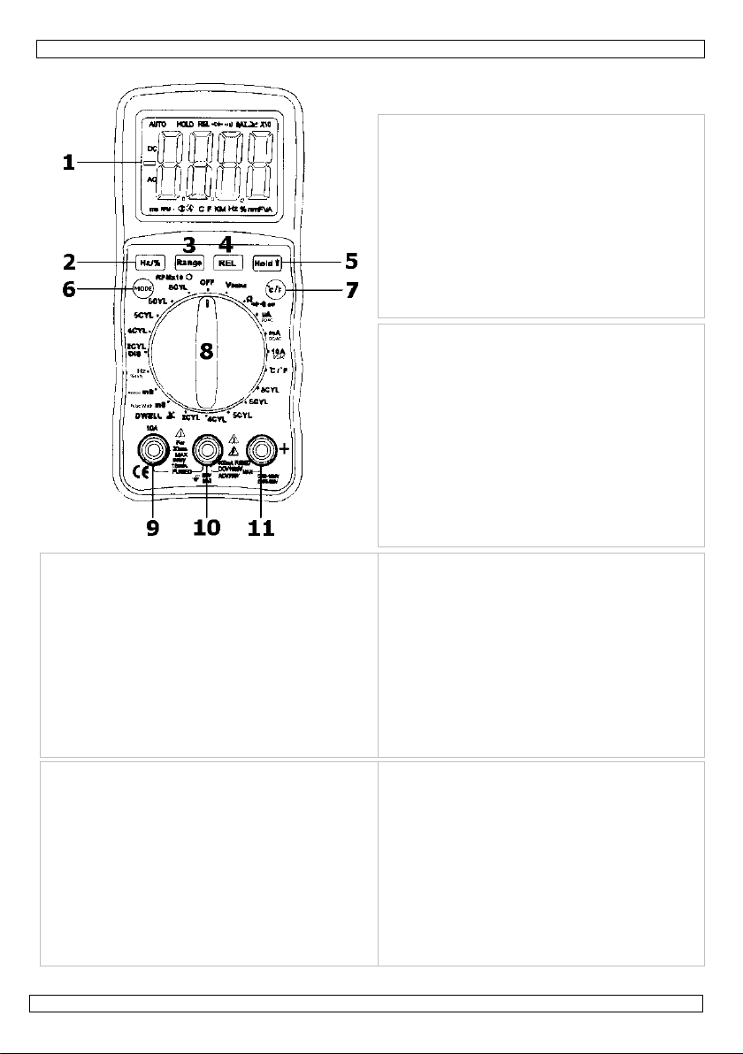
1. Display: large 4-digit LCD with symbol
indications.
2. Frequency / duty cycle button (HZ/%)
3. Range button
4. Relative button
5. Data hold / backlight button
6. Mode button
7. Temperature °C/°F button
8. Selection switch: to turn the power on or off
and select the measurement function and
range.
9. 10A (positive) input jack.
10. COM (negative) input jack.
11. + (positive) input jack for all other
measurements than 10A.
1. LCD-scherm: groot 4-digits LCD-scherm met
symboolaanduidingen.
2. Schakelknop frequentie / werkingscyclus
(Hz/%)
3. Bereikknop (Range)
4. Relatiefknop (REL)
5. Data Hold / achtergrondverlichtingsknop
6. Modeknop
7. Temperatuur °C/°F-knop
8. Selectieschakelaar: om het toestel in en uit te
schakelen en meetfunctie en -bereik te
bepalen.
9. 10A-aansluiting (positief)
10. COM (negatieve) aansluiting
11. + (positieve) aansluiting voor alle andere
1. Afficheur: LCD 4 digits avec indication de
symboles.
2. Bouton fréquence/cycle de fonctionnement
3. Bouton "Range" (portée).
4. Bouton REL (relatif)
5. Bouton Data Hold / éclairage de l'écran
6. Bouton Mode.
7. Bouton température °C/°F
8. Sélecteur: pour activer et désactiver l’appareil et
pour sélectionner la fonction et la plage de la
mesure.
9. Connecteur 10A (positif)
10. Connecteur COM (négatif)
11. Connecteur + (positif) pour tout autre mesurage
ue 10A
1. LCD-Display: großes 4-stelliges LCD-Display mit
Symbolanzeigen.
2. Taste Frequenz- / Arbeitszyklus (Hz/%)
3. Bereichstaste (Range)
4. Bezugswerttaste (REL)
5. Taste Data Hold / Hintergrundbeleuchtung
6. Mode-Taste
7. Temperatur °C/°F-Taste
8. Drehschalter: zum Ein- und Ausschalten des
Gerätes und für die Auswahl von Bereich und
Funktion.
9. 10A-Anschluss (positiv)
10. COM-Anschluss (negativ)
11. + (positiver) Anschluss für alle anderen
Messun
en als 10A
metingen dan 10A
1. Display: pantalla LCD de 4 dígitos con
indicación de símbolos.
2. Botón de frecuencia/ciclo de funcionamiento
3. Botón "Range" (rango).
4. Botón REL (relativo)
5. Botón Data Hold / retroiluminación
6. Botón "Mode".
7. Botón temperatura °C/°F
8. Selector: para activar y desactivar el aparato y
para seleccionar la función y el rango de la
medición.
9. Conector 10A (positivo)
10. Conector COM (negativo)
11. Conector (positivo) para cualquier medición
distinta a 10A
1. Display: LCD a 4 cifre con indicazione simboli.
2. Tasto Frequenza / Duty cycle (HZ/%)
3. Tasto Portata (Range)
4. Tasto Misurazione relativa (REL)
5. Tasto Memorizzazione dato (Hold) /
Retroilluminazione
6. Tasto Modalità (MODE)
7. Tasto Temperatura (°C/°F)
8. Selettore rotativo: permette di
accendere/spegnere lo strumento e di
selezionare la funzione e la portata.
9. Boccola 10A (positivo).
10. Boccola COM (negativo).
11. Boccola + (positivo) utilizzata per tutte le
misurazioni eccetto 10A.
05.01.2010 ©Velleman nv
2
Page 3
t
e
a
u
o
o
a
c
a
g
t
f
g
g
a
f
t
u
r
e
a
V
A
c
n
o
e
o
d
s
o
o
c
e
w
f
d
o
a
u
2
p
f
w
a
r
o
e
h
u
l
u
l
r
l
t
l
t
l
s
e
r
i
o
y
e
d
o
f
d
r
o
a
e
r
e
V
o
r
e
t
t
s
o
n
e
n
r
t
e
i
s
n
s
n
W
h
u
d
u
s
g
e
c
D
A
C
t
h
o
o
m
p
c
e
s
c
o
u
u
a
f
h
o
o
r
m
i
a
o
M
d
r
v
w
h
k
e
t
a
e
h
e
i
r
e
m
o
r
e
f
h
M
e
t
d
e
a
v
e
a
c
v
r
y
t
n
a
m
t
a
C
n
1. In
To all r
Import
If in do
Thank y
into serv
installati
• Famili
• All mo
modifi
• Only u
the w
• Dama
and th
• Refer
2. Sa
• Do not
it is no
• Never
outlets
wearin
materi
• Turn o
curren
• Be cau
• When
• Measu
expos
on the
• Never
VDC or
mA DC/
A DC/AC
Frequen
capacita
cycle, di
SAFETY
roduction
sidents of th
nt environme
This symbol
lifecycle coul
Do not dispo
specialized c
This device s
Respect the l
bt, contact y
u for buying th
ice. If the devi
n of this devic
rise yourself
difications of t
ations to the
se the device
rranty.
e caused by
e dealer will n
o the Vellem
ety Preca
use your DVM
t operating pro
round yoursel
, fixtures, etc.
dry clothing
l.
f the power to
can be dange
tious when wor
sing the probe
ing voltage tha
the operator t
front of the m
pply voltage o
AC
C
y, resistance, t
ce, pulse widt
de test, contin
SYMBOLS
Func
This symbo
operator m
This symbo
death or se
This symbo
damage to
This symbo
circuit poin
This symbo
ranges that
maximum
are energiz
European Un
ntal informati
n the device o
harm the env
e of the unit (
mpany for rec
hould be return
ocal environme
ur local wast
e DVM205AM!
e was damage
.
ith the functi
he device are
device is not c
or its intende
isregard of ce
t accept resp
n® Service
tions
05AM if the d
erly.
when making
hich might be
nd shoes with
the circuit und
ous.
king above 60
s, make sure t
t exceeds the li
a shock haza
ter.
r current to the
tion
emperature,
, dwell period,
ity, RPM
adjacent to an
st refer to an
indicates a po
ious injury.
indicates a po
he device.
advises the u
at which the v
adjacent to o
may, in norma
afety, the met
d.
DVM20
User m
ion
on about this
the package i
ronment.
r batteries) as
cling.
ed to your dist
ntal rules.
disposal au
Please read th
in transit, you
ns of the dev
orbidden for
overed by the
purpose. Usi
tain guideline
nsibility for a
nd Quality
evice itself or t
lectrical meas
at ground pote
ubber soles an
r test before c
DC or 30VAC a
keep your fin
mits of the mul
d. Always resp
meter that ex
1000V
400m
10A D
duty
other symbol,
er that the ter
e or more term
l use, be subje
250VD
xplanation in t
entially hazard
entially hazard
ltage with res
r and its test l
5AM
anual
product
dicates that di
unsorted muni
ibutor or to a l
horities.
manual thoro
should contact
ce before act
afety reasons.
warranty.
g the device i
in this manu
y ensuing de
arranty on t
e test leads lo
rements. Do n
ntial. Keep you
using rubber
tting, unsolder
such voltages
ers behind the
timeter may d
ct the meter v
eeds the specif
C; 750VAC
DC/AC
/AC (30 secon
C/AC
erminal or ope
is manual to a
us situation,
us situation w
inal(s) so mar
ect to ground
inals identifies
ted to particul
ads should not
posal of the d
ipal waste; it s
cal recycling s
ghly before br
your dealer an
ally using it.
Damage caus
n an unautho
l is not cover
ects or proble
e last pages
k damaged, o
t touch expos
body isolated
ats or other a
ng or breaking
pose a shock
finger guards o
mage your DV
ltage and curr
ied maximum:
aximum Inpu
s max every 1
ating device in
oid injury or d
hich if not avoi
ich, if not avoi
ed must not b
xceeds (in this
hem as being
rly hazardous
be handled wh
vice after its
ould be taken
rvice.
nging this devi
d postpone
ed by user
ised way will
d by the war
s.
f this manual.
if you suspect
d metal pipes,
rom ground b
pproved insula
it. Small amou
azard.
n the probes.
205AM and
nt limits as st
5 minutes)
icates that the
amage to the
ded, could resu
ded, may resul
connected to
case) 500V A
ssociated with
oltages. For
n these termi
to a
e
oid
anty
that
ing
ts of
ted
eter.
lt in
in
/DC.
als
05.01.201
0
3
©Vellem
n nv
Page 4

o
L
e
p
r
r
r
s
r
a
e
e
g
a
8
2
4
5
6
8
a
)
a
a
e
a
e
a
n
)
D
m
s
r
n
o
u
e
ge
0
0
0
0
m
V
V
V
m
V
V
V
µ
µA
m
m
µ
A
m
m
Ω
k
-
0
c
d
p
o
0
.
2
a
s
R
°
m
V
m
0
m
V
m
0
µ
µA
µ
01mA10m
µ
A
µ
01mA
m
Ω
Ω
y
g
C
n
0
y
a
m
a
1
2
W
0
r
%
%
%
%
%
%
%
%
%
%
%
%
%
%
%
%
%
%
a
u
R
%
s
o
y
o
o
a
7
o
0
m
o
o
0
a
m
o
c
a
v
l
0
2
d
2
0
a
c
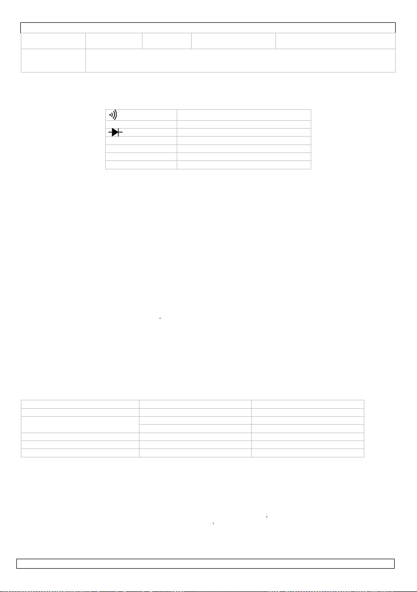
3. Fr
Refer to
SYMBO
4. Sp
Com
Insul
Ove
Displ
Pola
Ove
LowMea
Auto
Ope
Stor
Max.
Pollu
Pow
Dim
Wei
Fuse
All accur
RPM 2DWELL
DWELL
DWELL
DWELL
DWELL
DC volt
(autoranging
AC volt
(auto-r
except
400mV)
DC curr
(auto-r
for µA a
mA)
AC curr
(auto-r
for µA a
mA)
Resista
(autoranging
nt Panel
page 2 of this
S
cification
liant with
ation
voltage catego
ay
ity
range indicatio
battery indicati
urement rate
power off
ating temperat
ge temperatur
altitude (indoo
tion degree
r source
nsions
ht
cy indications
Ran
CYL 500~1
CYL 0~180
CYL 0~90.
CYL 0~72.
CYL 0~60.
CYL 0~45.
400.0
4.000
ge
40.00
400.0
1000V
400.0
ge
4.000
nging
40.00
nt
nging
nt
nging
ce
400.0
750V
400.0
4000
40.00
400.0
4A
10A
400.0
4000µ
40.00
400.0
4A
10A
400.0
4000
40.00
nd
nd
DVM20
escription
anual.
BAT
DATA HOLD
AUTO
AC
DC
Continuity
Low Batter
Diode
Data Hold
Auto rangin
Alternating
Direct Curre
IEC1010
Class2, d
y CATIII 6
large 4-d
automati
“OL”
n “BAT” is
2 times
device p
re 0°C to 5
-20°C to
rs) 2000m
2
one 9V-b
146 x 66
approx.
400mA r
below are valid
Re
0000 RPM 10
.0°
°
°
°
°
V 0.1
1m
10
10
1V
V 0.1
1m
10
10
A 0.1
1
A 10
A 10
A 0.1
1µ
A 10
A 10
Ω 0.1
1Ω
Ω 10
1 EN61010-1
ouble insulatio
0V, CATII 100
igit LCD with s
, negative pol
isplayed when
er second, no
wers off after
°C (32°F to 12
60°C (-4°F to
attery (e.g. 6F
2 x 41.5 (H x
00g
nge: 250V / 5
for 18-28°C (6
olution Accu
PM ±2.5
±2.5
0.1
V ±0.5
V
mV
V ±1.5
±1.0
V
mV
1V
A ±1.0
A
A
A
A ±1.5
A
µA
10
A
±1.2
±1.2
5AM
urrent or Volt
nt or Voltage
V
mbol signs
rity indication
the battery vol
inal
pprox. 15 min
2°F) @ <70%
40°F) @ <80
2)
0mA fast blow
5-83°F) @ <70
acy
rdg ±4 digits
rdg ±4 digits
rdg ±2 digits
rdg ±2 digits
±1.5
±1.8
rdg ±2 digits
rdg ±30 digit
rdg ±3 digits
rdg ±3 digits
±1.5
±2.0
rdg ±4 digits
rdg ±3 digits
rdg ±3 digits
±1.5
rdg ±5 digits
±2.5
rdg ±5 digits
rdg ±5 digits
±1.8
rdg ±7 digits
±3.0
rdg ±4 digits
±1.0
rdg ±2 digits
rdg ±2 digits
x D)
e
tage drops bel
tes of inactivit
H
RH
/ 10A range: 2
% RH.
other
Overload pr
rms
Overload pr
rms
Input imped
Max. input:
Input imped
Frequency r
Max input:
Overload pr
and 10A/25
Max. input:
rms on µA/
10Adc rms
Overload pr
and 10A/25
Frequency r
Max. input:
rms on µA/
10Aac rms
Input prote
w operating le
50V/10A fast b
tection: 250Va
tection: 250Va
ance: 10MΩ
1000Vdc rms
ance: 10MΩ
nge: 50 to 40
50Vac rms
tection: 0.5A/
V fuse
400mA
A ranges
n 10A range
tection: 0.5A/
V fuse
nge: 50 to 40
400mA
A ranges
n 10A range
tion: 250Vdc/a
el
ow
c/dc
c/dc
Hz
50V
c
50V
Hz
c
rms
05.01.201
0
4
©Vellem
n nv
Page 5
DVM205AM
g
p
y
g
g
Ran
Capacitance
(autoranging)
Frequency
(autoranging)
Duty cycle 0.1%~99.9% 0.1% ±1.2% rdg ±2 digits
Period
Pulse width
Temperature
Diode test 0.3mA typical 1mV ±10% rdg ±5 digits
Audible
Continuity
e Resolution Accuracy other
400.0kΩ 100 Ω
4.000MΩ 1kΩ
40.00MΩ 10kΩ ±2.0% rdg ±3 digits
40.00nF 10
400.0nF 0.1nF
4.000µF 1nF
40.00µF 10nF
100.0µF 0.1µF ±5.0% rdg ±5 digits
9.999Hz 0.001Hz
99.99Hz 0.01Hz
999.9Hz 0.1Hz
9.999kHz 1Hz
99.99kHz 10Hz
999.9kHz 100Hz
9.999MHz 1kHz ±1.5% rdg ±4 digits
2.0ms~
20.0ms
2.0ms
~10.0ms
-20~+760°C 1°C ±3% rdg ±3 digits
-4~+1400°F 1°F
Audible threshold: less than 50Ω
Test current: <0.3mA
Overload protection on all ran
F ±5.0% rdg ±7 digits
±3.0% rdg ±5 digits
±1.5% rdg ±5 digits
±1.2% rdg ±3 digits
0.1ms ±3% rdg ±10 digits
0.1ms ±3% rdg ±10 digits
(meter only ; probe
accurac
es: 250Vdc/ac rms
not included)
Input protection: 250Vdc/ac rms
Sensitivity:
<0.5Vrms while ≤1MHz
>3Vrms while >1MHz
Overload protection: 250Vdc/ac
rms
Pulse width: >100µs, 100ms
Frequency width: 5Hz-150kHz
Sensitivity: <0.5Vrms
Overload protection: 250Vac/dc
rms
Overload protection: 250Vac/dc
rms
Overload protection: 250Vac/dc
rms
Sensor: K-type thermocouple
Open circuit voltage: 1.5Vdc
typical
Overload protection: 250Vac/dc
rms
5. Control Buttons
a) Hz / % Button (fig. p.2 #2)
This button allows you to choose between frequency and the duty cycle in a frequency range.
Press the HZ/% button to measure the frequency or the duty cycle while measuring voltage or current.
For the voltage/current requirements and frequency range, see the following table (for reference only):
e (AC/DC) Sensitivity Frequency width
Ran
4V ≥1.5V rms 5Hz~10kHz
40V, 400V
1000V/750V ≥420V rms 50Hz~1kHz
400mA ≥45mA rms 5Hz~5kHz
10A ≥4A rms 5Hz~1kHz
Press the HZ/% button again to return to regular voltage or current measurement.
b) Range Button (fig. p.2 #3)
When the meter is switched on, it automatically goes into auto ranging ("AUTO" indication on the
display). This automatically selects the best range for the measurements being made and is generally the
best mode for most measurements. For measurements situations requiring a manually selected range,
perform the following steps:
1. Press the RANGE button; the "AUTO" indication on the display will disappear.
2. Press the RANGE button repeatedly to skip through the available ranges until the required one is
selected.
3. To return to auto ranging, press and hold the RANGE button for more than 2 seconds.
c) Relative Button (fig. p.2 #4)
The relative measurement feature allows you to make measurements relative to a stored reference
value. A reference voltage, current etc. can be stored and measurements made in comparison to that
value. The displayed value is the difference between the reference value and the measured value.
1. Perform any measurement as described in the operating instructions.
≥6.5V rms 5Hz~20kHz
≥12V rms 5Hz~200kHz
05.01.2010 ©Velleman nv
5
Page 6

DVM205AM
2. Press the REL(ative) button to store the reading in the display and the REL indication will appear on
the display.
3. The display will now indicate the difference between the stored value and the measured value.
4. Press the REL button to switch the relative function off and return to normal operation.
d) Data Hold / Backlight Button (fig. p.2 #5)
The data hold function allows the meter to "freeze" a measurement for later reference.
1. Press the DATA HOLD button to freeze the reading on the display. The HOLD indication will be
displayed.
2. Press the DATA HOLD button again to return to normal operation.
Press the button for more than 2 seconds to switch the display backlight on or off.
e) Mode Button (fig. p.2 #6)
Use the Mode button to select AC/DC voltage, AC/DC current, resistance, diode, continuity or capacitance
check.
f) °C/°F Button (fig. p.2 #7)
The °C/°F button is used to switch between °C and °F when measuring temperature.
The default temperature unit is °C.
6. Operating Instructions
1. Set the selection switch to the OFF position when the device is not being used. In order to prevent
battery leakage, the device automatically powers down when it has not been used for approx. 15
minutes.
2. If "OL" appears in the display during a measurement, the value exceeds the selected range. Select a
higher range.
3. When a low voltage range is selected, the display may show a varying reading although the leads are
not connected to a device or circuit. This is normal and is caused by the high input sensitivity. The
reading will stabilize and give a proper measurement when connected to a circuit.
a) Voltage Measurements
1. Plug the black test lead in COM (fig. p.2 #10) and the red test lead in the + connector (#11).
2. Set the selection switch (#8) to the Vdc/ac position and press MODE (#6) to select AC or DC voltage.
3. Put the leads over the load to be measured and read the measured value from the LCD.
NOTE: Pressing the Hz/% button will cause the display to switch to frequency or duty cycle.
b) Current Measurements
CAUTION: Do not make current measurements on the 10A scale for longer than 30 seconds every 15
minutes. Exceeding 30 seconds may cause damage to the meter and/or the test leads.
1. Plug the black test lead in the COM jack (#10) and the red test lead in the + jack (11) for max.
400mA measurements, or in the 10A jack (#9) for max. 10A measurements.
2. Set the selection switch (#2) to the desired current measuring position (µA, mA or A).
3. Press MODE (#6) to select AC or DC current.
4. Put the leads in series with the load under test and read the measured value from the LCD.
NOTE: Pressing the Hz/% button will cause the display to switch to frequency or duty cycle.
c) Resistance / Diode / Continuity / Capacitance Measurements
CAUTION: To avoid electric shock, make sure all power of the circuit to be measured is off and all
capacitors are fully discharged when measuring resistance or capacitance.
1. Plug the black test lead in COM and the red test lead in the + connector (#11).
2. Set the selection switch (#8) to the Ω CAP position.
3. Press the MODE button to select Ω, or CAP.
4. Connect the test leads to the component or circuit to be measured and read the measured value from
the LCD.
5. When testing continuity, a beeping sound shall be heard if the resistance is <30Ω.
6. When measuring the forward voltage across a diode, a normal diode will indicate 0.4V or 0.7V. The
reverse voltage will indicate "OL" (same as in open condition). A short-circuited diode will have a
0mV reading.
d) Frequency or Duty Cycle Measurements
1. Plug the black test lead in COM and the red test lead in the + connector (#11).
2. Set the selection switch (#8) to the Hz/%duty position.
3. Press the Hz/% button to select "Hz" or "%".
4. Connect the test leads to the circuit under test and read the frequency or the duty cycle on the
display.
e) Temperature Measurements
1. Insert the type K thermocouple in the appropriate sockets: negative plug in COM, positive plug in +.
2. Set the selection switch (#2) to °C/°F.
3. Press the °C/°F button to select °C or °F.
05.01.2010 ©Velleman nv
6
Page 7
L
P
t
n
d
h
P
t
n
d
R
1
t
h
n
e
k
D
1
t
h
n
e
k
N
e
D
y
I
e
n
e
R
w
A
s
f
o
R
w
r
e
s
e
s
m
e
g
s
e
e
e
e
s
e
m
w
n
h
o
e
e
m
i
e
o
a
o
n
n
i
d
e
d
s
n
d
u
d
s
d
e
g
s
d
e
g
e
d
t
s
r
B
s
u
u
o
d
a
s
a
a
s
a
e
a
e
t
c
n
l
e
u
e
d
e
s
n
o
d
e
g
e
d
d
n
n
e
e
u
a
V
r
n
s
e
m
e
t
t
o
o
c
1
o
w
e
a
w
a
o
n
n
o
o
e
c
t
n
t
e
h
4. Touc
the
f)
1. Plug
2. Set
3. Con
be m
4. Rea
NOTE: T
g)
1. Plug
2. Set
3. Con
be m
4. Rea
h)
1. Plug
(#1
2. Set
on t
3. Con
the r
4. Cran
i)
1. Plug
(#1
2. Set
on t
3. Con
the r
4. Cran
NOTE:
7. Ma
CAUTIO
to avoid
closed s
If your
not fault
a)
The batt
and ope
6F22 or
b)
The fuse
the scre
250V/10
Use thi
event o
For mor
The inf
© COPY
This manu
No part of
the prior
h the target su
CD.
eriod Measur
the black test l
he selection sw
ect the black te
easured.
the measured
e applied time
ulse Width M
the black test l
he selection sw
ect the black te
easured.
the measured
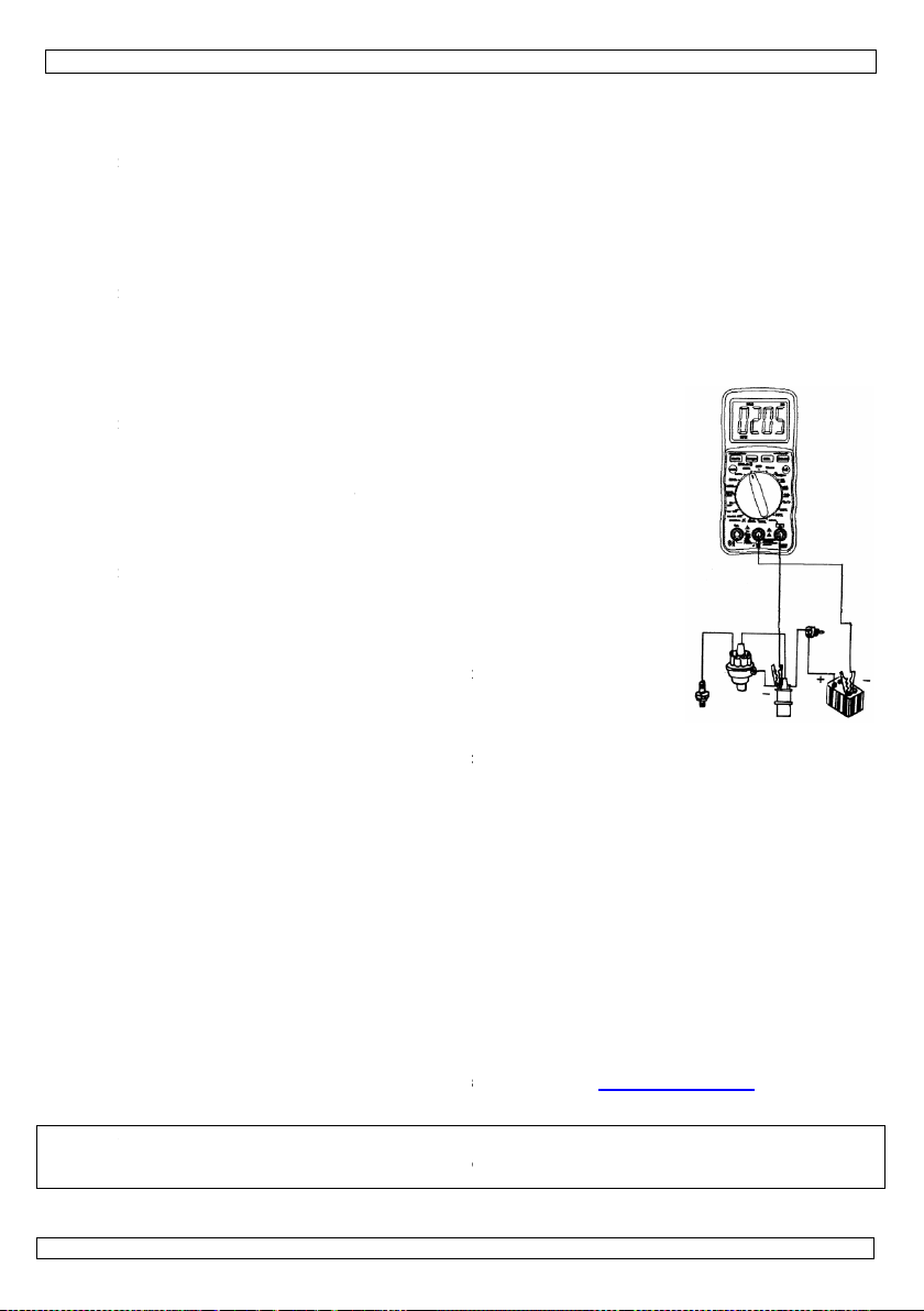
PM Measure
the black test l
).
he selection sw
e RPMx10 ran
ect the black te
d test lead to a
the engine; th
well Angle M
the black test l
).
he selection sw
e DWELL rang
ect the black te
d test lead to a
the engine; th
The dwell ang
ignition syste
to have the d
intenance
: Before openi
electric shock
curely.
VM205AM sh
and are prop
nstall or Repl
ry should be r
the case. Re
quivalent) - m
eplace a Fus
rarely needs t
s at the back
fast blow for
device with
damage or i
e info concer
rmation in th
IGHT NOTICE
al is copyrighted.
this manual may
ritten consent of
face with the e
ements
ad in COM an
itch (#2) to "P
t lead to groun
value on the di
for most fuel i
easurements
ad in COM an
itch (#2) to "P
t lead to groun
value on the di
ents
ad in COM an
itch (#2) to th
e).
t lead to the ne
breaker point.
RPM (rotation
asurements
ad in COM an
itch (#2) to th
).
t lead to the ne
breaker point.
dwell angle wil
le needs only b
. Cars with an
ell angle teste
g the case, se
azard. Do not
uld not be ope
rly inserted.
ace a Battery
placed when “
ove the old bat
nd the polarity
be replaced; a
nd open the ca
10A range), clo
riginal acces
jury resulted
ing this prod
s manual is s
The copyright t
be copied, reprod
the copyright hol
DVM20
xtremity of the
the red test le
riod ms".
and the red te
play.
jectors is displ
the red test le
lse Width ms".
and the red te
play.
the red test le
applicable pos
ative pole of th
per minute) wil
the red test le
applicable pos
ative pole of th
l be displayed.
tested in cars
electronic igni
.
the selection s
witch the devi
ating properly,
AT” appears o
tery (when rep
! Close the cas
blown fuse is
se. Replace th
se the case an
ories only. V
from (incorre
ct, please vi
bject to cha
this manual is
uced, translated
er.
5AM
probe and rea
d in the + con
t lead to the wir
yed on the ne
d in the + con
t lead to the wir
d in the + con
ition (2, 4, 5, 6
car battery an
l be displayed.
d in the + con
ition (2, 4, 5, 6
car battery an
with a traditio
ion system don
witch to OFF a
e on before th
check the batt
the display. T
acing) and inst
and tighten th
sually the resu
old fuse (250
tighten the sc
lleman nv ca
ct) use of thi
it our websit
ge without pr
owned by Velle
r reduced to any
the measured
nector (#11).
that connects
ative (-) slope.
nector (#11).
that connects
nector
or 8CYL
connect
nector
or 8CYL
connect
al
't need
d disconnect al
battery/fuse c
ry and fuses t
rn loose the s
ll a new one (
e screws.
lt of the operat
/0.5A fast blo
ews.
not be held r
device.
www.vellem
ior notice.
an nv. All world
lectronic medium
temperature fr
o the compone
o the compone
l test leads in
mpartment do
make sure th
rews at the ba
x 9V-battery
r's error. Turn
for 400mA ra
sponsible in
n.eu.
ide rights reserv
or otherwise wit
m
t to
t to
rder
r is
y are
k
ype
loose
ge;
he
d.
out
05.01.201
0
7
©Vellem
n nv
Page 8
e
v
t
g
v
u
r
a
a
d
i
r
m
o
e
e
p
p
s
o
n
e
s
r
a
A
t
s
H
v
f
o
n
n
e
p
s
e
n
g
e
e
r
m
i
o
t
o
a
s
d
k
p
o
n
p
a
L
a
a
e
j
a
h
r
e
e
f
h
n
e
p
r
a
s
t
e
n
e
t
b
n
f
o
d
m
e
n
P
e
i
n
e
e
j
n
o
e
k
t
s
d
r
s
e
o
g
f
g
e
t
0
m
V
o
t
j
e
e
u
m
o
v
e
t
o
a
k
e
e
s
v
b
o
e
e
j
M
3
a
s
h
l
t
p
v
k
n
v
d
i
d
g
g
k
e
0
j
s
p
k
n
k
a
o
n
u
n
g
s
u
n
o
e
g
k
v
e
1. Inl
Aan all
Belangr
Dank u
het toes
raadplee
•
Leer
•
Om
gebr
•
Geb
•
De g
uw d
verb
•
Raa
2. Ve
• Geb
ver
• Zorg
en v
drog
and
• Kop
com
zijn.
• Wee
vero
• Als u
• Spa
en d
zoal
• Geb
Vdc of V
mA DC/
A DC/AC
Frequen
werking
capacitei
VEILIG
eiding
ingezetenen
ijke milieu-in
Dit symbool
weggeworpe
batterijen) ni
terechtkome
recyclagepun
Hebt u vrag
oor uw aankoo
el niet werd be
uw dealer.
eerst de functi
eiligheidsrede
iker heeft aan
uik het toestel
rantie geldt ni
ealer zal de ve
nd mee houde
pleeg de Velle
ligheidsvo
uik uw DVM20
oedt dat het to
ervoor dat u n
orwerpen aan
kleren en sch
r isolerend ma
el altijd de str
onenten wilt a
voorzichtig bij
rzaken.
de meetprobe
ningen meten
operateur ele
beschreven o
uik de meter n
c
C
ie, weerstand,
cyclus, temper
t, diodetest, on
EIDSSYMBO
an de Europ
ormatie betr
p het toestel o
, dit toestel sc
et bij het gewo
voor recyclag
t brengen. Res
n, contactee
! Lees deze h
chadigd tijden
s van het toes
en mag u geen
ebracht valt ni
nkel waarvoor
t voor schade
antwoordelijkh
n.
orschrifte
5AM niet als h
estel niet naar
et geaard bent
die op aardepo
enen met rub
eriaal).
omtoevoer los
n toevoegen o
spanningen h
gebruikt, hou
ie boven de li
trische schokk
het toestel.
oit met spanni
Fu
ctie
ulsbreedte, O
tuur, continuït
derbrekingsper
EN
mbool naast ee
Dit sy
cht moet sche
aand
besch
diging aan de
Geeft
een gevaarlijk
hebb
n.
Geeft
een gevaarlijk
Vermi
d aansluitinge
Geva
rlijke spanning
veilig
eid.
Geb
an® service-
DVM20
uikersh
se Unie
ffende dit pr
de verpakking
ade kan toebr
e huishoudelij
. U moet dit to
ecteer de plaa
dan de plaat
ndleiding gron
het transport.
el kennen voor
wijzigingen aa
et onder de ga
het gemaakt i
door het neger
id afwijzen vo
en kwaliteits
t toestel zelf o
behoren werkt.
als u elektrisch
entiaal kunnen
er zolen te dra
aar een schak
van weghalen
ger dan 60Vdc
deze dan vast
iet van de mul
n toebrengen.
gen of stroom
100
400
M,
it,
ode
n ander symbo
ken aan de ins
meter te vermi
situatie weer
situatie weer
aan een circui
. Vermijd gebr
10A
250
5AM
andleidi
duct
geeft aan dat,
ngen aan het
e afval; het m
estel naar uw
selijke milieuw
elijke autori
ig voor u het t
Zo ja, stel dan
u het gaat geb
nbrengen. Sch
antie.
. Bij onoordeel
n van bepaald
r defecten of p
arantie acht
de meetprobe
e metingen uit
zijn. Bescherm
en en door ru
ling die u wilt
. Kleine hoevee
en 30Vac; dez
achter de ving
imeter liggen,
Respecteer alti
die de maxima
Vdc; 750Vac
A DC/AC
DC/AC (max.
dc/ac
l, terminal of t
ructies in de h
den.
n kan tot kwet
n kan tot besc
t met een span
ik van de mete
ng
als het na zijn
ilieu. Gooi dit
et bij een ges
erdeler of naar
tgeving.
eiten inzake
estel in gebrui
de installatie v
ruiken.
de door wijzigi
undig gebruik
richtlijnen in
roblemen die h
raan deze han
er beschadigd
oert. Raak gee
uw lichaam te
ber matjes te
nderbreken of
lheden stroom
kunnen elektri
rbescherming
kan uw DVM2
d de spanning
le waarden ove
aximum In
0 seconden el
oestel geeft aa
ndleiding om
uren leiden of
adiging van de
ning hoger dan
r en meetsnoer
evenscyclus w
oestel (en eve
ecialiseerd bed
een lokaal
erwijdering.
neemt. Ga na
an het toestel
gen die de
ervalt de gara
eze handleidin
er rechtstreek
leiding.
uitzien, of als
n metalen leidi
en aarding do
ebruiken (of e
waar u
unnen gevaarl
sche schokken
n.
5AM beschadi
- en stroomlim
rschrijden:
t
e 15 minuten)
dat de gebrui
wetsuren en
de dood tot ge
meter leiden.
500 VAC of VD
en voor uw eig
rdt
tuele
rijf
of
it en
tie.
en
gen
r
n
ijk
en
ieten
er
olg
C.
n
05.01.201
0
8
©Vellem
n nv
Page 9

DVM205AM
g
g
g
g
g
g
g
g
p
Bereik Resolutie Nauwkeuri
RPM 2-8CYL
500~10000
RPM
10RPM
±2.5% v/d uitlezing
±4 di
heid andere
its
Overbelastingsbeveiliging:
250Vac/dc rms
DWELL 2CYL 0~180.0°
DWELL 4CYL 0~90.0°
DWELL 5CYL 0~72.0°
DWELL 6CYL 0~60.0°
0.1°
±2.5% v/d uitlezing
±4 digits
Overbelastingsbeveiliging:
250Vac/dc rms
DWELL 8CYL 0~45.0°
DC-spanning
(automatische
bereikbepaling)
400.0mV 0.1mV ±0.5% ±2 di
4.000V 1mV
40.00V 10Mv
±1.5% ±2 digits
400.0V 100Mv
its
Ingangsimpedantie: 10MΩ
Overbelastingsbeveiliging:
1000Vdc rms
1000V 1V ±1.8% of rdg± 2 dgts
AC-spanning
(automatische
bereikbepaling
behalve 400mV)
DC-stroom
(automatische
bereikbepaling
voor µA en mA )
AC-stroom
(automatische
bereikbepaling
voor µA en mA )
Weerstand
(automatische
bereikbepaling)
400.0mV 0.1mV ±1.5% ±30 di
4.000V 1mV ±1.0% ±3 digits
40.00V 10Mv
400.0V 100Mv
±1.5% ±3 digits
750V 1V ±2.0% ±4 digits
400.0µA 0.1µA ±1.0% ±3 di
4000µA 1µA
40.00mA 10µA
±1.5% ±3 digits
400.0mA 100µA
4A 1mA
10A 10mA
±2.5% ±5 digits
400.0µA 0.1µA ±1.5% of rd
4000µA 1µA
+
1.8% of rdg + 5 dgts 40.00mA 10µA
400.0mA 100µA
4A 1mA
10A 10mA
3.0% of rdg + 7 dgts
+
400.0 Ω 0.1Ω ±1.2% ±4 di
4000 Ω 1Ω ±1.0% ±2 digits
40.00kΩ 10Ω
400.0kΩ 100Ω
±1.2% ±2 digits
4.000MΩ 1kΩ
its
its
±5 dgts
its
Ingangsimpedantie: 10MΩ
Frequentiebereik: 50 tot 400Hz
Max. ingangsspanning: 750Vac
rms
Overbelastingsbeveiliging:
zekering 0.5A/250V zekering
10A/250V
Max. ingang: 400mAdc rms in
µA/mA bereik, 10Adc rms in 10A
bereik
Overbelastingsbeveiliging:
zekering 0.5A/250V zekering
10A/250V
Max. ingang:400mAdc rms in
µA/mA bereik10Adc rms in 10A
bereik
Ingangsbeveiliging: 250Vdc/ac
rms
40.00MΩ 10kΩ ±2.0% ±3 digits
Capaciteit
(automatische
bereikbepaling)
40.00nF 10pF ±5.0% ±7 di
400.0nF 0.1nF
4.000µF 1nF
±3.0% ±5 digits
40.00µF 10nF
its
Ingangsbeveiliging: 250Vdc/ac
rms
100.0µF 0.1µF ±5.0% ±5 digits
Weerstand
(automatische
bereikbepaling)
9.999Hz 0.001Hz
99.99Hz 0.01Hz
999.9Hz 0.1Hz
9.999kHz 1Hz
99.99kHz 10Hz
999.9kHz 100Hz
±1.5% ±5 digits
±1.2% ±3 digits
Gevoeligheid:
<0.5Vrms bij ≤1MHz
>3Vrms bij >1MHz
Overbelastingsbeveiliging:
250Vdc/ac rms
9.999MHz 1kHz ±1.5% ±4 digits
Pulsbreedte: >100µs, 100ms
Werkingscyclus
Periode
Pulsbreedte
Temperatuur
Diode test
05.01.2010 ©Velleman nv
0.1%~99.9% 0.1% ±1..2% of rdg±2 dgts
2.0ms~
20.0ms
2.0ms~
10.0ms
-20~+760°C 1°C +
-4~+1400°F 1°F
typisch
0.3mA
0.1ms ±3% of rdg±10 dgts
0.1ms ±3% of rdg±10 dgts
3% of rdg +3dgts
(Enkel voor de
multimeter,
nauwkeurigheid sonde
niet be
aald)
1mV ±10% of rdg±5 dgts
9
Frequentiebreedte: 5Hz-150kHz
Gevoeligheid: <0.5Vrms
Overbelastingsbeveiliging:
250Vac/dc rms
Overbelastingsbeveiliging:
250Vac/dc rms
Overbelastingsbeveiliging:
250Vac/dc rms
Sensor: K-type thermokoppel
Spanning open schakeling:
typisch 1.5Vdc
Page 10
s
L
e
n
l
i
m
m
s
g
w
d
o
d
e
d
B
g
r
m
k
l
t
d
r
ï
f
g
l
r
e
n
o
Z
m
e
k
p
n
b
T
t
b
2
4
a
“
v
g
n
t
t
-
6
0
4
e
)
e
a
s
u
o
t
A
e
a
s
o
o
1
t
0
t
i
e
d
t
t
F
x
e
g
b
s
s
s
s
a
c
e
n
o
b
ging
k
n
g
u
v
e
0
8
o
a
1
s
n
n
e
w
a
a
e
N
m
d
a
b
H
H
k
H
H
H
m
d
v
t
n
a
V
e
m
b
e
e
Hoorba
continu
test
3. Be
Zie figuu
SYMBO
4. Sp
Conform
Isolatie
Overspa
Scherm
Polariteit
Buitenbe
'Batterij
Meetsnel
Automat
Werkte
Opslagte
Maximu
Vervuilin
Voeding
Afmetin
Gewicht
Zekering
Alle nau
5. Be
a) '
Deze kn
Druk op
meet. D
voorbeel
Druk no
b) '
Wannee
scherm).
voor de
stappen:
1. Dru
2. Druk
gese
3. Om
inge
e
teits-
Hoor
ests
Over
chrijving
r op blz. 2
EN
cificaties
met
ningcategorie
reik aanduidin
aag'-aanduidin
heid
sche uitschake
peratuur
mperatuu
hoogte (binn
gsgraad
bron
en
keurigheidsaa
ieningskn
Hz / %' knop
p laat u toe te
e HZ/% knop
spanning/stro
):
ereik (AC/DC
4V
40V, 400V
1000V/750V
400mA
10A
eens op de H
Range' knop (
de meter aang
Zo wordt auto
eeste meting
op de RANGE
herhaaldelijk o
ecteerd is.
erug te keren
rukt.
are grens: min
room: <0.3m
elastingsbeveil
rontpanee
BAT
DATA HOLD
AUTO
AC
DC
“OL”
g
ing toestel
nshuis) 2000m
duidingen in d
IEC101
Klasse
CATIII
groot
autom
BAT”
vervan
2 meti
0°C to
-20°C
2
één 9V
146 x
ong. 2
Bereik
Bereik
der dan 50Ω
i
l
0-1 EN61010-
, dubbele isola
600V, CATII 1
-digits LCD me
tische aanduid
erschijnt op d
en
gen per secon
schakelt zichze
50°C (32°F to
ot 60°C (-4°F
batterij (bv. 6
6.2 x 41.5 (H
0g
00mA: 250V /
10A: 250V / 10
tabel hierond
oppen
(fig. blz.2 #2)
kiezen tussen f
om de frequent
mvereisten en
/% knop om t
fig. blz.2 #3)
ezet wordt, ga
atisch het be
n. Voor meting
nop ; de aand
de RANGE kn
aar de automa
requentie of de
ie of de werkin
het frequentie
rug te keren n
t hij automatis
te bereik gesel
en die een ma
iding "AUTO"
p om door de
ische bepaling
DVM20
alle berei
Continuït
Zwakke b
Diode
Data Hold
Automati
Wisselstr
Gelijkstro
Gevoelighe
≥1.5V rm
≥6.5V rm
≥12V rms
≥420V rm
≥45mA rm
≥4A rms
5AM
en: 250Vdc/ac
it
tterij
che bereikinste
om of –spanni
m of –spannin
ie
00V
symboolaand
ng van negatie
display wanne
e, nominaal
lf uit nadat het
122°F) @ <7
ot 140°F) @ <
22)
B x D)
0.5A snelle do
A snelle doorsl
r gelden voor
werkingscyclu
scyclus te met
ereik vindt u i
id
ar gewone spa
h het bereik b
cteerd voor u
uele bereikbep
p het scherm z
eschikbare ber
houdt u de RA
Overbelasti
250Vac/dc r
rms
lling
idingen
e polariteit
r de batterij
15 seconden ni
%RH
0%RH
rslag
g
8-28°C (65-83
in een bepaal
en terwijl u spa
de volgende t
Frequentie
5Hz~10k
5Hz~20k
5Hz~200
50Hz~1k
5Hz~5k
5Hz~1k
ning- of stroo
palen (aandui
metingen, en
ling vereisen,
l verdwijnen.
iken te gaan to
GE knop lange
gsbeveiliging:
ms
oet worden
et gebruikt is
°F) @ <70% R
frequentieber
nning of stroo
bel (enkel als
ereik
z
z
Hz
z
z
z
meting.
ing "AUTO" op
werkt ook het
olgt u de volg
het gewenste
r dan 2 second
ik.
het
est
nde
n
05.01.201
0
10
©Vellem
n nv
Page 11

DVM205AM
c) 'Relative' knop (fig. blz.2 #4)
Met deze knop kunt u metingen doen waarbij de relatieve waarde weergegeven wordt: een
referentiespanning, -stroom etc. kan opgeslagen worden en nieuwe metingen worden weergegeven in
verhouding tot die waarde. De weergegeven waarde is het verschil tussen de opgeslagen waarde en de
gemeten waarde.
1. Voer eender welke meting uit zoals weergegeven in de bedieningsinstructies.
2. Druk op de REL(atieve) knop om de gemeten waarde op te slaan ; de aanduiding REL verschijnt op
het scherm.
3. Het scherm zal nu het verschil tussen de gemeten en de opgeslagen waarde weergeven.
4. Druk op de REL-knop om de relatieve functie uit te schakelen en terug te keren naar normale
werking.
d) 'Data Hold' / achtergrondverlichting knop (fig. blz.2 #5)
Met de 'data hold' functie kunt u een meting "bevriezen" om later als referentie te gebruiken.
1. Druk op de DATA HOLD knop om de uitlezing op het scherm te bevriezen. De aanduiding HOLD zal
verschijnen.
2. Druk nog eens op de DATA HOLD knop om terug te keren naar normale werking.
Hou de knop langer dan 2 seconden ingedrukt om de achtergrondverlichting aan of uit te zetten.
e) 'Mode' knop (fig. blz.2 #6)
Selecteer AC/DC spanning, AC/DC stroom, weerstand, diode, continuïteit of capaciteitcontrole met de
Mode knop.
f) '°C/°F' knop (fig. blz.2 #7)
De °C/°F knop wordt gebruikt om te schakelen tussen °C en °F bij temperatuurmetingen.
De standaard temperatuureenheid is °C.
6. Bedieningsinstructies
1. Zet de selectieschakelaar op de OFF-stand wanneer het toestel niet gebruikt wordt. Om de batterij te
sparen en lekken te voorkomen, schakelt het toestel zichzelf uit als het gedurende 15 minuten niet
wordt gebruikt.
2. "OL" tijdens een meting wijst op een hogere waarde dan het geselecteerde bereik. Selecteer een hoger
bereik.
3. Als een laag spanningsbereik geselecteerd is, kan de meter een schommelende uitlezing vertonen,
hoewel de meetprobes niet verbonden zijn met een toestel of schakeling. Dit is normaal en wordt
veroorzaakt door de hoge ingangsgevoeligheid. Tijdens de eigenlijke meting zal de meter een
stabiele en correcte uitlezing geven.
a) Spanning meten
1. Steek de zwarte meetprobe in de COM-aansluiting (fig. blz.2 #10) en de rode probe in the "+"aansluiting (#11).
2. Zet de selectieschakelaar (#8) op de Vdc/ac-stand en druk op MODE (#6) om AC of DC spanning te
selecteren.
3. Plaats de probes over de te meten belasting en lees de gemeten waarde af van het LCD-scherm.
OPMERKING: door op de Hz/% knop te drukken schakelt u tussen frequentie en werkingscyclus.
b) Stroom meten
OPGELET: meet geen stroom op de 10A-schaal gedurende langer dan 30 seconden per kwartier. Langer
meten dan 30 seconden kan de meter en/of de meetprobes beschadigen.
1. Steek de zwarte meetprobe in de COM-aansluiting (fig. blz.2 #10) en de rode probe in the "+"aansluiting (#11) voor metingen tot 400mA of in de 10A-aansluiting voor metingen tot 10A.
2. Zet de selectieschakelaar (#8) op de gewenste stroomstand (µA, mA of A).
3. Druk op MODE (#6) om AC of DC stroom te selecteren.
4. Plaats de meetprobes in serie met de te meten belasting en lees de gemeten waarde af van het LCDscherm.
OPMERKING: door op de Hz/% knop te drukken schakelt u tussen frequentie en werkingscyclus.
c) Weerstand / Diode / Continuïteit / Capaciteit meten
OPGELET: Zorg ervoor dat er geen stroom door de te meten schakeling vloeit en dat alle capaciteiten
volledig ontladen zijn als u weerstand of capaciteit gaat meten. Dit om elektrische schokken te
vermijden.
1. Steek de zwarte meetprobe in de COM-aansluiting (fig. blz.2 #10) en de rode probe in the "+"aansluiting (#11).
2. Zet de selectieschakelaar (#8) op de Ω CAP-stand.
3. Druk op MODE om Ω, , of CAP te selecteren.
4. Verbind de meetprobes met de te meten component of schakeling en lees de gemeten waarde af van
de LCD.
5. Bij de continuïteitstest hoort u een piepgeluid wanneer de weerstand <30Ω is.
05.01.2010 ©Velleman nv
11
Page 12

s
0
F
k
d
k
T
k
d
k
k
P
k
d
p
I
P
k
d
p
O
k
o
d
L
i
g
O
k
o
d
L
i
I
'
t
s
c
B
p
g
s
w
k
n
m
e
k
n
v
n
k
m
a
e
k
m
a
e
k
R
e
a
s
e
k
"
e
o
o
i
k
t
z
g
e
u
C
d
m
d
°
F
e
C
d
t
t
C
d
t
C
g
d
e
n
w
C
g
d
e
n
e
o
i
e
s
h
k
r
e
n
s
a
s
d
a
s
e
e
a
m
d
d
b
0
a
)
a
a
)
o
)
o
)
5
e
)
5
e
e
t
k
h
b
r
e
o
O
w
o
e
-
o
e
r
o
h
w
a
a
e
l
e
e
e
e
d
a
6. De d
sper
een
d)
1. Stee
aans
2. Zet
3. Dru
4. Verb
e)
1. Stee
+.
2. Zet
3. Dru
4. Raa
LCD.
f)
1. Stee
aans
2. Zet
3. Verb
com
4. Lees
OPMERK
g)
1. Stee
aans
2. Zet
3. Verb
com
4. Lees
h)
1. Stee
de r
2. Zet
8CY
3. Verb
rode
4. Start
weer
i)
1. Stee
de r
2. Zet
8CY
3. Verb
rode
4. Start
OPMERK
auto
elek
gete
7. On
WAARSC
zijn voor
aan voor
Als uw D
en corre
a)
Vervang
los en o
9V-batte
05.01.201
oorlaatspannin
panning zal al
mV-uitlezing.
requentie of
de zwarte me
luiting (#11).
e selectiescha
op de Hz/%-k
ind de meetpro
emperatuur
het type K th
e selectiescha
op de °C/°F-k
het doelopper
eriode mete
de zwarte me
luiting (#11).
e selectiescha
ind de zwarte
onent.
de gemeten w
NG: De period
ulsbreedte m
de zwarte me
luiting (#11).
e selectiescha
ind de zwarte
onent.
de gemeten w
over een diod
"OL" uitgeleze
erkingscycl
etprobe in de
elaar (#8) op
op om "Hz" of
bes met de te
eten
rmokoppel in
elaar (#8) op
op om °C of °
lak aan met h
etprobe in de
elaar (#8) op "
eetprobe met
arde af van he
voor de mees
eten
etprobe in de
elaar (#8) op "
eetprobe met
arde af van he
PM meten
de zwarte me
de probe in th
e selectiescha
op het bereik
nd de zwarte m
meetprobe met
de motor ; het
egeven.
nderbreking
de zwarte me
de probe in th
e selectiescha
op het bereik
nd de zwarte m
meetprobe met
de motor ; de
NG: de
s met een trad
ronisch ontste
t te worden.
etprobe in de
"+"-aansluitin
elaar (#8) op
PMx10).
etprobe met d
een onderbreki
antal OPM (om
hoek meten
etprobe in de
"+"-aansluitin
elaar (#8) op
DWELL").
etprobe met d
een onderbreki
nderbrekingsho
nderbrekingsh
tionele ontstek
ingssysteem di
derhoud
HUWING: Zorg
u de behuizing
het deksel van
VM205AM nie
t aangesloten
atterij plaats
de batterij wan
en de behuizin
rij, type 6F22 o
0
ervoor dat de
opent; dit zal
het batterij/ze
behoorlijk we
ijn.
en of vervang
neer de meded
. Verwijder de
f equivalent), s
DVM20
zal voor een
n worden (zoal
s meten
OM-aansluiting
e Hz/%duty-st
"%" te selecter
eten schakelin
e correcte aan
C/°F.
te selecteren.
t uiteinde van
OM-aansluiting
Period ms".
e aarding en d
scherm.
e injectoren st
OM-aansluiting
Pulse Width m
e aarding en d
scherm.
OM-aansluiting
(#11).
e toepasselijke
negatieve pool
gspunt.
entelingen per
OM-aansluiting
(#11).
e toepasselijke
negatieve pool
gspunt.
k wordt weerg
ek dient enkel
ng. Bij wagens
nt de onderbr
electieschakel
et risico op ele
eringcomparti
kt, controleer
en
ling “BAT” op
oude batterij (
luit de behuizin
12
5AM
ormale diode
in open toest
(fig. blz.2 #10
nd.
en.
g en lees de w
luitingen: neg
e probe en lee
(fig. blz.2 #10
e rode meetpr
at vermeld op
(fig. blz.2 #10
".
e rode meetpr
(fig. blz.2 #10
positie (2, 4,
van de batterij
minuut) wordt
(fig. blz.2 #10
positie (2, 4,
van de batterij
geven.
getest te word
met een
kingshoek niet
ar op OFF staa
ktrische schok
ent stevig dic
an eerst of de
e LCD verschij
ij vervanging )
g en zet de sch
.4 of 0.7V bed
nd). Een kortg
en de rode pr
arde af van de
tieve plug in C
s de gemeten
en de rode pr
be met de kab
de negatieve (
en de rode pr
be met de kab
en
, 6 of
n de
en
, 6 of
n de
n in
en dat alle p
en wegnemen.
tgemaakt is.
atterij en zeke
nt. Maak de sc
, sluit een nieu
roeven terug v
agen ; de
sloten diode h
be in the "+"-
LCD.
M, positieve p
aarde af van d
be in the "+"-
l naar de te m
) hellingshoek.
be in the "+"-
l naar de te m
bes losgekopp
Zet het toestel
ringen nog goe
roeven achter
e batterij aan
st.
©Vellem
eft
ug in
ten
ten
ld
niet
zijn
an
(1 x
n nv
Page 13

Z
r
b
k
h
e
r
g
R
d
t
i
t
i
o
d
u
l
u
m
m
c
a
é
e
u
b
t
r
n
s
a
e
n
m
o
a
t
n
t
e
t
z
s
t
o
w
e
i
i
)
e
m
c
t
t
q
t
V
e
t
a
t
d
s
x
e
m
n
r
m
t
g
t
g
s
O
n
e
u
n
h
v
e
a
g
n
t
m
o
e
é
a
ê
c
6
R
;
o
s
e
n
g
o
o
s
n
x
e
r
e
s
a
e
V
p
d
t
r
s
u
e
5
m
o
m
n
i
I
c
m
e
t
à
t
n
v
s
o
e
n
o
f
r
e
o
p
z
e
p
t
e
s
i
o
i
e
d
s
h
t
v
e
a
t
)
e
e
s
i
r
e
t
h
r
t
n
s
b)
De zeke
resultaat
Vervang
sluit de
Gebrui
voor sc
Voor m
De info
vooraf
© AUTEU
Velleman
Alle werel
kopiëren,
toestemm
ekering verv
ing dient slech
van een fout v
de oude zekeri
ehuizing en ze
dit toestel
ade of kwe
er informati
matie in de
aande kenni
SRECHT
nv heeft het au
wijde rechten vo
e vertalen, te be
ng van de rechth
ngen
s zelden verva
an de gebruike
g (250V / 500
de schroeven
nkel met ori
suren bij (ve
e omtrent di
e handleidin
geving.
eursrecht voor
rbehouden. Het i
erken en op te sl
bbende.
N
DVM20
gen te worden
. Maak de schr
A voor het 40
erug vast.
inele acces
rkeerd) gebr
product, zi
kan te alle
deze handleidin
niet toegestaan
aan op een elektr
TICE D
5AM
gewoonlijk is
even achteraa
0mA-bereik; 2
oires. Velle
uik van dit t
www.velle
tijde worde
.
m deze handleid
nisch medium zo
’EMPLO
en doorgebran
n los en open d
0V / 10A voor
an nv is niet
estel.
an.eu.
gewijzigd
ng of gedeelten e
nder voorafgaand
de zekering he
e behuizing.
het 10A-bereik
aansprakelij
onder
rvan over te nem
schriftelijke
,
k
n, te
1. In
Aux rés
Des inf
En cas
Nous vo
l’apparei
revende
•
Se fa
•
Toute
modifi
•
N’utilis
•
La gar
notice
résulte
•
Se réf
2. Pr
• N'utilis
fonctio
• Ne vo
ou d'o
des vê
ou aut
• Décon
compo
• Faites
• Quand
• Mesur
expose
à l’ava
• Ne ja
menti
roduction
dents de l'Un
rmations env
Ce symbole
peut polluer
éventuelles
l’appareil en
de recyclag
l’environne
e questions,
s remercions d
. Si l’appareil a
r.
iliariser avec le
odification es
ations par le cl
er qu’à sa fonc
ntie ne s’appli
et votre revend
nt.
rer à la garan
scriptions
ez pas votre D
nne mal.
s mettez pas à
jets métalliqu
ements secs e
e matière isola
ectez l'aliment
ants. Une peti
ttention avec
vous utilisez le
r des tensions
r l'opérateur au
t du multimètr
ais utiliser le
nnées:
on européen
ronnemental
sur l'appareil o
l'environneme
parmi les déc
question. Ren
local. Il convi
ent.
ontacter les
e votre achat !
été endomma
fonctionneme
interdite pour
ient ne tomben
ion prévue. Un
ue pas aux do
eur déclinera t
ie de service
de sécurit
M205AM si l'
la terre quand
s qui peuvent
des chaussure
trice.
tion du circuit
e quantité de
es tensions >
s probes, tenez
upérieures aux
électrochocs.
.
ultimètre avec
e
s importante
l'emballage i
t. Ne pas jeter
ets municipau
oyer les équip
nt de respecte
utorités local
Lire la présent
é pendant le tr
t avant l’emplo
des raisons de
pas sous la g
usage impropr
mages surven
ute responsabi
t de qualité
ppareil ou les
vous faites des
tre à potentiel
s à semelles en
sous test avan
ourant peut êt
0Vcc ou 30Vca
-les derrière le
limites du multi
espectez toujo
un courant ou
concernant
dique que l’éli
un appareil él
non sujets au
ments usagés
la réglementa
es pour élimi
notice attenti
ansport, ne pa
i.
écurité. Les d
rantie.
annule d'offic
us en négligea
lité pour les pr
elleman® en
robes sont end
mesures électr
e terre. Isolez
caoutchouc et
de l'interromp
e dangereux.
afin d'éviter d
protections de
mètre peut end
urs les limites d
ne tension su
e produit
ination d’un a
ctrique ou élec
ri sélectif ; un
votre fournis
ion locale relat
ation.
ement avant la
l’installer et c
mmages occas
la garantie.
t certaines dir
blèmes et les
in de notice.
ommagés, ou
iques. Ne touc
votre corps de
en utilisant un
e ou d'en enle
s électrochocs.
doigts.
mmager votre
e courant et de
érieurs aux val
pareil en fin d
ronique (et de
déchèterie tra
eur ou à un se
ve à la protecti
mise en servic
nsulter votre
onnés par des
ctives de cette
éfauts qui en
i l'appareil
ez pas de cond
la terre en por
apis en caoutc
er ou y ajoute
appareil et peu
tension mentio
urs maximale
vie
piles
tera
vice
on de
de
uites
ant
ouc
des
nées
05.01.201
0
13
©Vellem
n nv
Page 14

c
C
c
L
s
r
L
é
e
e
r
o
h
m
e
o
e
-
o
n
p
n
é
A
o
a
p
e
a
x
o
P
r
u
A
AAU
C
C
s
g
n
e
l
0
1
9
7
6
4
04.0
e
c
R
m
c
u
t
u
t
r
m
0
s
I
à
a
“
”
a
à
C
e
x
é
é
e
s
0
0
1
04010
5ITÉ
o
o
u
g
n
o
T
u
T
u
a
1
n
t
à
H
V
1
o
P
%
%
%
%
a
t
a
u
c
s
n
p
%
0
s
p
5
m
e
u
e
s
u
u
a
f
m
%
c
c
e
1
a
e
h
o
i
a
a
Vcc ou V
mA CC/
A CC/CA
Fréquen
d'impulsi
test du d
SYMBO
3. De
Voir figu
SYMBO
4. Sp
Conform
Isolation
Catégori
Afficheu
Polarité
Indicatio
Indicatio
Echantill
Débranc
Tempéra
Tempéra
Altitude
Degré d
Source d
Dimensi
Poids
Fusible
Toutes l
RPM 2
DWELL
DWELL
DWELL
DWELL
DWELL
Tensi
05.01.201
a
A
e, résistance,
on, cycle de fo
iode, continuit
ES CONCERN
Ce symb
contraint
endomm
Situation
n’est pas
Situation
as évité
A termin
voltage e
Ce symb
tension.
de l’appa
cription d
e à la p.2.
ES
cification
avec
de survoltage
n hors plage
n pile faible
nnage
ement automa
ture de travail
ture de stocka
aximale (à l'i
pollution
’alimentation
ns
s indications d
8CYL 500~1
2CYL 0~
4CYL 0~
5CYL 0~
6CYL 0~
8CYL 0~
n CC
0
Fo
ction
ériode de cam
ctionnement,
, température,
NT LA SÉCU
le près d’un sy
à lire les instru
ements au m
potentiellemen
évitée.
dangereuse po
..
l marked with
ceeds 500VAC
le près d’une o
our votre sécu
ition de ce sy
panneau
B
D
TA HOLD
TO
A
D
CATI
tique l'app
e -20°
térieur) 2000
précision ci-d
P
age Ré
000 RPM 1
80.0°
0.0°
2.0°
0.0°
5.0°
40
.0mV 0
00V
, largeur
apacité,
RPM
bole, d’une b
tions dans la n
ltimètre.
dangereuse p
vant engendre
his symbol sho
or VDC above
u plusieurs bor
ité, reporter l’u
bole.
frontal
IEC1
10-1 EN61010
Clas
e2, double isol
I 600V, CATII
LCD
4 digits avec i
indic
tion automatiq
“OL”
BAT
apparaît quan
sures par seco
2 me
reil s'éteint au
0°C
50°C (32°F à
à 60°C (-4°F
m
2
1 pil
9V (p. ex. 6F2
146
66.2 x 41.5 (
env.
200g
e 400mA: 250
port
port
e 10A: 250V /
ssous valent p
olution
RPM ±2.5
.1° ±2.5
.1mV ±0.5
mV ±1.5
DVM20
Continuité
Pile faible
Diode
Maintien d
Instaurati
ension o
ension o
5AM
1
00Vcc ; 750Vc
0mA CC/CA
A CC/CA (max
2
0Vcc/ca
rne ou apparei
otice afin d’évi
uvant engendr
r des endomm
ld not be conn
round.
es indique que
tilisation du m
e la lecture affi
n automatique
courant altern
courant direct
-1
tion
000V
ndication de sy
ue de polarité
d la tension dé
de, nominal
omatiquement
122°F) @ <70
140°F) @ <8
2)
x La x P)
/ 500mA à fu
0A à fusion ra
ur 18-28°C (6
récision
aff. ±4 digits
aff. ±4 digits
aff. ±2 digits
aff. ±2 digits
14
Entrée maxi
. 30 sec. chaqu
l indique que l’
er des blessur
er des blessure
gements au m
ected to a circ
celles-ci pourr
ltimètre et les
hée
de la gamme
atifs
mboles
égative
asse le niveau
après env. 15
RH
%RH
ion rapide
ide
-83°F) à <70
Autres
Protection sur
rms
Protection sur
rms
Impédance d'
Entrée max.:
ale
15 minutes)
tilisateur est
s ou
ou la mort si
ltimètre si elle
it point of whic
ient être sous
ils de mesure l
opérationnel
inutes d'inact
HR
harge: 250Vc
harge: 250Vc
ntrée: 10MΩ
000Vcc rms
©Vellem
lle
n’est
the
rs
vité
/cc
/cc
n nv
Page 15

DVM205AM
g
g
g
g
g
g
p
T
g
Pla
Tension CA
Courant CC
Courant CA
Résistance
Capacité
Fréquence
Cycle de
fonctionneme
nt
Période
Largeur
d'im
ulsion
Température
Test de diode
Continuité
audible
0.1%~99.9% 0.1% ±1.2% aff.±2 digits
e Résolution Précision Autres
40.00V 10mV
400.0V 100mV
1000V 1V ±1.8% aff. ±2 digits
400.0mV 0.1mV ±1.5% aff.±30 di
4.000V 1mV ±1.0% aff.±3 digits
40.00V 10mV
400.0V 100mV
750V 1V ±2.0% aff.±4 digits
400µA 0.1µA ±1.0% aff.±3 di
4000µA 1µA
40.00mA 10µA
400.0mA 100µA
4A 1mA
10A 10mA
400µA 0.1µA ±1.5% aff.±5 di
4000µA 1µA
40.00mA 10µA
400.0mA 100µA
4A 1mA
10A 10mA
400.0 Ω 0.1Ω ±1.2% aff.±4 di
4000 Ω 1Ω ±1.0% aff.±2 digits
40.00kΩ 10Ω
400.0kΩ 100 Ω
4.000MΩ 1kΩ
40.00MΩ 10kΩ ±2.0% aff.±3 digits
40.00nF 10pF ±5.0% aff.±7 di
400.0nF 0.1nF
4.000µF 1nF
40.00µF 10nF
100.0µF 0.1µF ±5.0% aff.±5 digits
9.999Hz 0.001Hz
99.99Hz 0.01Hz
999.9kHz 0.1Hz
9.999kHz 1Hz
99.99kHz 10Hz
999.9kHz 100Hz
9.999MHz 1kHz ±1.5% aff.±4 digits
2.0ms~
20.0ms
2.0ms~
10.0ms
-20~+760°C 1°C +
-4~+1400°F 1°F
typiquement
0.3mA
0.1ms ±3% aff.±10 digits
0.1ms ±3% aff.±10 digits
1mV ±10% aff.±5 digits
±1.5% aff.±3 digits
±1.5% aff.±3 digits
±2.5% aff.±5 digits
±1.8% aff.±5 digits
±3.0% aff.±7 digits
±1.2% aff.±2 digits
±3.0% aff.±5 digits
±1.5% aff.±5 digits
±1.2% aff.±3 digits
3% of aff. +3dgts
(Pour le multimètre
uniquement,
précision pour la
sonde non précisée)
Seuil audible: <50 Ω.
Courant de test: <0.3mA
Protection surchar
e: 250Vcc/ca
its
Impédance d'entrée: 10MΩ
Plage de fréquence: 50 à 400Hz
Entrée max.: 750Vca rms
its
Protection surcharge: fusible
0.5A/250V et fusible 10A/250V
Entrée max.: 400mAcc dans les
champs µA/mA 10Acc dans le
champ 10A
its
Protection surcharge: fusible
0.5A/250V et 10A/250V
Plage de fréquence: 50 à 400Hz
Entrée max.: 400mAcc dans les
champs µA/mA 10Acc dans le
champ 10A
its
Protection surcharge: 250Vcc/ca
rms
its
Protection surcharge: 250Vcc/ca
rms
Sensibilité:
<0.5Vrms à ≤1MHz
>3Vrms à >1MHz
Protection surcharge: 250Vcc/ca
rms
Largeur d'impulsion: >100µs,
100ms
Largeur de fréquence: 5Hz-150kHz
Sensibilité: <0.5Vrms
Protection surcharge: 250Vca/cc
rms
Protection surcharge: 250Vca/cc
rms
Protection surcharge: 250Vca/cc
rms
Senseur: thermocouple type K
ension circuit ouvert:
typiquement 1.5Vcc
Protection surcharge: 250Vca/cc
rms
05.01.2010 ©Velleman nv
15
Page 16

DVM205AM
(
5. Boutons
a) Bouton Hz/% (fig. p.2 #2)
Ce bouton vous permet de choisir entre la fréquence ou le cycle de fonctionnement dans une portée de
fréquence.
Pressez le bouton Hz/% pour mesurer la fréquence ou le cycle de fonctionnement pendant que vous
mesurez du voltage ou du courant. Pour les exigences et gammes de fréquence voltage/courant,
consultez la table suivante (uniquement pour référence):
Portée
Pressez le bouton Hz/% encore une fois pour retourner au mesurage normal de tension ou de courant.
b) Bouton "Range" (portée) (fig. p.2 #3)
Quand le mètre est allumé, il détermine automatiquement la portée du mesurage (indicateur AUTO sur
l'écran).
Dans la plupart des cas, c'est le meilleur mode pour des mesurages. Pour sélectionner la portée
manuellement, suivez les étapes suivantes:
1. Pressez le bouton RANGE ; l'indicateur AUTO disparaîtra de l'écran.
2. Pressez le bouton RANGE plusieurs fois pour parcourir les différentes portées et sélectionner la plus
adéquate.
3. Pour retourner à la détermination automatique, pressez le bouton RANGE pendant plus de 2
secondes.
c) Bouton REL (fig. p.2 #4)
La fonction relative vous permet de faire des mesurages relatifs à une valeur de référence. Une tension
ou un courant de référence peut être sauvegardé et des mesurages peuvent être effectués en
comparaison avec cette valeur. La valeur affichée est la différence entre la valeur de référence et la
valeur réelle.
1. Faites n'importe quel mesurage comme indiqué dans la notice.
2. Pressez REL pour sauvegarder la valeur indiquée comme valeur relative. "REL" sera affiché sur
l'écran.
3. Dès maintenant, l'écran va afficher la différence entre la valeur réelle et la valeur de référence.
4. Pressez le bouton REL pour désactiver la fonction relative et pour donc retourner au fonctionnement
normal.
d) Bouton Data Hold / éclairage de fond (fig. p.2 #5)
La fonction "data hold" vous permet de "geler" un mesurage pour référence plus tard.
1. Pressez le bouton HOLD pour geler la valeur sur l'écran. L'indication HOLD sera affichée.
2. Pressez le bouton HOLD encore une fois pour retourner au fonctionnement normal.
3. Pressez le bouton pendant plus de 2 secondes pour allumer/éteindre l'éclairage de fond.
e) Bouton Mode (fig. p.2 #6)
Utilisez ce bouton pour sélectionner tension ou courant CC/CA, résistance, diode, continuité ou capacité.
f) Bouton °C/°F (fig. p.2 #7)
Le bouton °C/°F sert à déterminer si l'affichage est en °C ou en °F.
CA/CC) Sensibilité Gamme de fréquence
4V ≥1.5V rms 5Hz~10kHz
40V, 400V ≥6.5V rms 5Hz~20kHz
≥12V rms 5Hz~200kHz
1000V/750V ≥420V rms 50Hz~1kHz
400mA ≥45mA rms 5Hz~5kHz
10A ≥4A rms 5Hz~1kHz
6. Instructions d'opération
1. Mettez le sélecteur sur la position OFF quand l'appareil n'est pas utilisé. Afin d'éviter des piles vides
ou coulantes, l'appareil s'éteint automatiquement s'il n'est pas utilisé pendant 15 minutes.
2. Si "OL" apparaît pendant un mesurage, la valeur dépasse la portée. Sélectionnez une portée plus haute.
3. Si une portée de tension basse est sélectionnée, l'écran peut afficher une valeur instable bien que les
probes ne sont pas connectés ou ils ne sont pas connectés à un appareil ou un circuit. C'est normal
et causé par la haute sensibilité d'entrée. Pendant un mesurage, l'affichage sera stabile et juste.
a) Mesurer la tension
1. Insérez la probe noire dans le connecteur COM (fig. p.2 #10) et la probe rouge dans le connecteur
"+" (#11).
2. Mettez le sélecteur (#8) à la position Vcc/ca et pressez MODE (#6) pour sélectionner la tension CA
ou CC.
3. Connectez les probes à la charge à mesurer et lisez la valeur mesurée sur l'écran.
REMARQUE: en pressant le bouton Hz/%, vous alternez entre fréquence et cycle de fonctionnement.
05.01.2010 ©Velleman nv
16
Page 17

M
I
r
(
u
e
s
n
U
M
I
p
r
(
e
s
n
e
m
M
r
(
e
s
n
M
r
t
e
s
M
r
(
e
n
z
U
M
r
e
e
n
p
z
M
r
e
e
é
n
e
a
M
r
e
e
é
u
r
n
(
e
t
e
(
e
n
'
q
(
z
e
m
(
C
c
r
(
u
g
e
(
e
u
P
e
(
;
e
(
a
e
q
o
n
%
h
o
o
e
c
o
t
m
n
o
t
é
o
e
r
i
o
e
o
é
R
o
o
m
n
g
é
C
e
e
n
e
d
g
P
A
u
n
0
r
g
u
F
b
g
g
g
t
g
t
m
a
t
a
n
a
a
t
n
a
r
f
a
u
m
a
u
a
Y
e
a
Y
c
o
d
d
f
r
d
e
m
d
u
d
s
a
r
e
.
à
e
é
e
e
b)
ATTENT
d'heure.
1. Insé
"+"
jusq
2. Mett
3. Pres
4. Con
REMARQ
c)
ATTENT
mesurer
ou du ca
1. Insé
"+"
2. Mett
3. Pres
4. Con
5. Lors
6. La t
(co
d)
1. Insé
"+"
2. Mett
3. Pres
4. Con
e)
1. Insé
posi
2. Mett
3. Pres
4. Touc
f)
1. Insé
"+"
2. Mett
3. Con
4. Lise
REMARQ
négative
g)
1. Insé
roug
2. Mett
3. Con
com
4. Lise
h)
1. Insé
roug
2. Mett
port
3. Con
à un
4. Dém
i)
1. Insé
roug
2. Mett
port
05.01.201
esurer le co
ON: ne mesu
Mesurer penda
ez la probe noi
#11) pour des
'à 10A.
z le sélecteur
ez MODE (#6)
ectez les prob
E: en pressan
esurer la rés
ON: Pour évit
et à ce que les
acité.
ez la probe noi
#11).
z le sélecteur
ez MODE pour
ectez les prob
d'un test de co
nsion directe d
me en conditio
esurer la fré
ez la probe noi
#11).
z le sélecteur
ez le bouton H
ectez les prob
esurer la te
ez le thermoco
ive dans +.
z le sélecteur
ez le bouton °
hez la surface
esurer la pé
ez la probe noi
#11).
z le sélecteur
ectez la probe
la valeur mes
E : La période
(-).
esurer la lar
ez la probe noi
dans le conn
z le sélecteur
ectez la probe
osant à mesur
la valeur mes
esurer les R
ez la probe noi
dans le conn
z le sélecteur
e RPMx10).
ectez la probe
vis platinée.
rrez le moteur
esurer l'angl
ez la probe noi
dans le conn
z le sélecteur
e "DWELL").
0
rant
ez pas de cour
t plus de 30 s
re dans le conn
mesurages jus
#8) à la positi
pour sélection
s en série avec
le bouton Hz/
istance / une
r des électroc
capacités sont
re dans le conn
#8) à la positi
sélectionner Ω,
s avec le comp
tinuité, vous e
une diode sera
n ouverte). Un
uence ou le
re dans le conn
#8) à la positi
/% pour sélec
s au circuit à
pérature
uple type K da
#8) à la positi
/°F pour sélec
ible avec l'extr
iode
re dans le conn
#8) à la positi
noire à la mass
rée sur l'écran.
appliquée pou
eur d'impuls
re dans le conn
cteur "+" (#11
#8) à la positi
noire à la mass
r.
rée sur l'écran.
M
re dans le conn
cteur "+" (#11
#8) à la positi
noire au pôle n
le nombre de
e d'interrupti
re dans le conn
cteur "+" (#11
#8) à la positi
DVM20
nt dans le cha
condes peut e
ecteur COM (fi
u'à 400mA ou
n de courant d
er du courant
la charge à m
, vous altern
diode / la co
ocs, veillez à c
complètement
ecteur COM (fi
n Ω CA
, ou C
sant ou le circ
ntendez un sig
normalement
diode court-ci
ycle de foncti
ecteur COM (fi
n Hz/%duty.
ionner "Hz" ou
esurer et lisez
s les connecte
n °C/°F.
ionner °C ou °
mité de la pro
ecteur COM (fi
n "Period ms".
et la probe ro
la plupart des
on
ecteur COM (fi
).
n "Pulse Width
et la probe ro
ecteur COM (fi
).
n applicable (2
gatif de la bat
PM (révolutions
n
ecteur COM (fi
).
n applicable (2
17
5AM
p 10A pendan
dommager le
. p.2 #10) et l
dans le connec
sirée (µA, mA
C ou CA.
surer et lisez l
z entre fréque
tinuité / la c
qu'il ne coule
échargées si v
. p.2 #10) et l
.
P.
it à mesurer e
al sonore qua
.4 ou 0.7V ; la
cuitée aura un
onnement
. p.2 #10) et l
"%".
la valeur mesu
rs correctes:
.
e et lisez la va
. p.2 #10) et l
uge au câble q
injecteurs est
. p.2 #10) et l
ms".
uge au câble q
. p.2 #10) et l
, 4, 5, 6 of 8C
erie et la prob
par minute) est
. p.2 #10) et l
, 4, 5, 6 of 8C
plus de 30 se
ètre ou les pr
probe rouge
eur 10A pour
ou A).
valeur mesuré
ce et cycle de
pacité
pas de courant
ous allez mesu
probe rouge
lisez la valeur
d la résistance
tension invers
affichage de 0
probe rouge
ée sur l'écran.
iche négative d
leur mesurée s
probe rouge
i va au compo
entionnée sur
probe
i va au
probe
L de la
rouge
indiqué.
probe
L de la
ondes par qua
bes.
ans le connect
es mesurages
e sur l'écran.
onctionnement
dans le circuit
er de la résista
ans le connect
mesurée sur l'
est <30Ω.
sera affichée "
V.
ans le connect
ans COM, fiche
r l'écran.
ans le connect
ant à mesurer.
la dénivellation
©Vellem
t
ur
nce
ur
cran.
OL"
ur
ur
n nv
Page 18

n
a
U
m
O
o
z
D
R
e
n
R
e
/
o
e
a
S
m
s
c
o
t
u
a
p
d
a
z
í
s
s
p
a
;
e
r
e
p
d
R
f
e
s
a
a
s
o
d
v
o
a
c
a
e
l
d
a
n
e
s
e
t
é
u
s
t
v
s
A
n
t
e
z
d
m
t
é
d
u
s
N
e
e
o
p
y
c
a
d
c
r
c
d
t
r
c
t
e
e
,
v
s
t
e
r
s
a
e
t
u
L
e
v
d
t
p
e
o
e
o
n
e
u
e
q
e
s
n
z
u
e
v
n
R
e
i
r
m
p
t
a
a
a
e
s
o
s
n
b
m
o
u
u
c
n
e
r
d
t
c
o
s
d
o
m
h
r
v
s
u
o
a
d
s
r
f
0
d
r
o
e
ñ
a
o
3. Con
4. Dém
REMARQ
7. Re
ATTENTI
électroch
N'allume
Si votre
fusibles.
a)
Remplac
Enlevez l
attentio
b)
Il est rar
l'opérate
ou 250V
N’empl
aucune
cet app
www.v
Toutes
notific
© DROIT
SA Velle
Tous droit
cette noti
l’ayant dr
ectez la probe
rrez le moteur
E: l'angl
traditi
mesu
placer la
N: Avant d'ouv
cs.
pas l'appareil a
VM205AM n
emplacer la
z la pile quan
a pile faible (si
à la polarité!
emplacer le
que les fusibl
ur. Dévissez le
10A à fusion r
yer cet app
ment respon
areil. Pour pl
lleman.eu.
les informati
tion préalabl
D’AUTEUR
an est l’ayant
mondiaux réser
e par quelque pr
it.
noire au pôle n
l'angle d'interr
d'interruption
onnel. Pour de
er.
pile
rir le boîtier, me
vant que le cou
fonctionne pa
ile
le message “B
applicable) et i
efermez le boî
usible
s doivent être
vis à l'arrière
pide), referme
reil qu’avec
able de do
us d’informa
ns présent
e.
roit des droits
és. Toute reprod
cédé ou sur tout
DVM20
gatif de la bat
ption est indiqu
ne doit être m
voitures à allu
tez le sélecteur
ercle des piles
comme il faut
T” est affiché.
sérez une nou
ier et serrez le
remplacés ; c'e
t ouvrez le boî
le boîtier et s
es accessoi
mages ou lé
ion concern
es dans cett
’auteur pour ce
ction, traduction,
upport électroniq
5AM
erie et la prob
é.
suré que dans
mage électroni
(#2) sur OFF et
t fusibles soit fe
vérifiez l'état
Dévissez les vi
elle (1 x pile 9
vis.
st généraleme
ier. Remplace
rrez les vis.
es d’origine.
ions surven
nt cet articl
notice peu
te notice.
copie ou diffusio
e que se soit est
rouge à une vi
des voitures av
ue, il n'y a poi
enlevez les pro
rmé convenable
t la connexion
à l'arrière et
V, type 6F22 o
t le résultat d'
le fusible défe
SA Vellema
s à un usag
, visitez not
ent être mo
, intégrale ou par
interdite sans l’a
s platinée.
ec un allumage
t besoin de le
es pour éviter
ent.
de la pile et de
uvrez le boîtie
équivalent) -
ne faute de
tueux (250V/5
ne sera
(incorrect)
e site web
ifiées sans
ielle, du contenu
cord préalable éc
es
.
aites
0mA
e
de
it de
1. In
A los ci
Import
Gracias
usarlo. S
distribui
•
•
•
•
•
2. In
• No use
• Evite e
05.01.201
Famili
Por ra
causad
Utilice
garant
Daños
y su di
Véase
funcion
estar
materi
roducción
dadanos de l
ntes informa
Este símbolo
dañar el med
No tire este
empresa esp
reciclaje loca
Si tiene dud
or haber comp
i el aparato ha
or.
rícese con el fu
ones de seguri
os por modific
sólo el aparato
a completame
causados por d
tribuidor no s
la Garantía de
truccione
el DVM205AM
a mal.
l contacto con
uestos a tierra.
l de aislamien
0
MA
Unión Europ
iones sobre
en este aparat
io ambiente.
parato (ni las
cializada en re
.Respete las le
as, contacte
rado el DVM20
sufrido algún d
ncionamiento
ad, las modifi
ciones no auto
para las aplica
te.
escuido de las i
rá responsable
servicio y cal
de seguri
cuando las pun
l suelo al hace
Mantenga su
o aprobado.
UAL DE
a
l medio ambi
o el embalaje
ilas, si las hubi
ciclaje. Devuel
es locales en r
on las autori
5AM! Lea aten
ño en el trans
el aparato ant
aciones no aut
izadas, no está
iones descritas
nstrucciones d
de ningún dañ
idad Vellema
ad
as de prueba o
mediciones. N
uerpo aislado
USUA
nte concerni
indica que, si t
era) en la basu
a este aparato
elación con el
ades locales
amente las ins
orte no lo inst
s de utilizarlo.
rizadas del ap
n cubiertos por
en este manu
seguridad de
u otros proble
®
al final de e
l aparato mism
o toque objeto
sando ropa sec
18
IO
nte a este pr
ra las muestra
a doméstica;
a su distribuid
edio ambiente
ara residuos.
rucciones del
le y póngase e
rato están pro
la garantía.
l. Su uso incor
ste manual in
mas resultante
te manual del
están dañados
metálicos ni c
a, zapatos de g
ducto
inservibles, p
ebe ir a una
r o a la unidad
.
anual antes d
n contacto con
ibidas. Los da
ecto anula la
alidarán su gar
.
suario.
o si el aparato
nductos que p
oma o cualquie
©Vellem
drían
de
su
os
ntía
drían
r otro
n nv
Page 19

n
ñ
c
g
o
a
C
c
d
c
p
L
s
g
L
p
n
a
d
r
r
d
á
e
o
s
c
o
R
s
c
m
a
u
I
u
V
m
n
a
n
n
i
R
t
g
o
i
u
u
m
a
a
e
o
0
e
I
d
a
s
a
i
°
2
a
x
0
e
s
e
>
t
o
o
A
C
c
a
a
t
o
d
d
o
T
c
T
c
d
1
n
c
n
g
e
2
A
0
a
P
u
o
a
e
s
e
x
u
p
ga
a
a
s
n
s
n
@
p
5
o
d
p
p
e
s
t
a
±
%
a
n
r
e
• Desco
peque
• Sea ex
eléctri
• Si usa
• Medir t
descar
aparat
• Nunca
Vcc o Vc
mA CC/
A CC/CA
Frecuen
capacida
parada,
rueba d
SÍMBO
3. De
Véase fi
SÍMBO
4. Es
Según
Aislamie
Categorí
Display
Polarida
Indicado
Indicado
Velocida
Auto apa
Tempera
Tempera
Altura m
Grado d
Alimenta
Dimensi
Peso
Fusible
Todas la
05.01.201
ecte la aliment
a cantidad de
tremadamente
as.
las puntas de p
ensiones superi
as eléctricas.
.
utilice una ten
¡Ojo! Cons
Este símbol
Este símbol
No conecte
500VAC o
Este símbol
seguridad
símbolo.
Fun
A
ia, resistencia,
, anchura de i
iclo de funcion
e diodo, contin
OS DE SEGUR
cripción d
ura en la p.2.
OS
ecificacio
to
de sobrecarg
de sobre rang
de batería baj
de medición
gado
tura de funcion
tura de almace
x. (en el interi
contaminació
ción
nes
siguientes ind
0
ación del circui
orriente puede
cuidadoso al m
rueba, manten
res a los límite
espete siempre
ión ni una corri
ión
temperatura,
pulsos, tiemp
miento, capac
idad, RPM
DAD
lte el manual d
o indica una sit
o indica una sit
una conexión
DC sobre mas
o al lado de un
áx., no utilice
el panel fr
BAT
DATA HOLD
AUTO
AC
DC
o a prueba ant
ser peligrosa p
edir tensiones
a los dedos de
s del multímetr
los límites de c
ente superior a
de
dad,
el usuario para
ación peligros
ación peligros
arcada con es
.
o más conexi
ste aparato ni
ntal
Continuida
Pila baja
Diodo
retención
Ajuste aut
ensión o
ensión o
es
IEC1
10-1 EN61010
Clas
CATI
o “OL”
a se vi
amiento de 0
amiento de -
or) 2000
2
caciones de pr
ango Re
2, aislamiento
I 600V, CATII
LCD
e 4 dígitos co
indic
ción automáti
ualiza “BAT” e
2 me
diciones por se
rato se apaga
el ap
inact
vidad
C a 50°C (de 3
0°C a 60°C (d
m
1 pil
9V (p.ej. 6F2
146
66.2 x 41.5 (
± 20
g
ce 400mA: 25
alcan
alcan
ce 10A: 250V /
cisión valen p
olución
DVM20
1000V
400m
10A C
250Vc
19
5AM
s de cortar, q
uede ser peligr
60Vcc o 30Vc
rás de las prot
podría dañar
rriente como s
los valores ma
cc ; 750Vca
CC/CA
/CA (máx. 30
/ca
evitar lesiones
que podría ca
que podría da
e símbolo a un
nes indica una
las puntas de
e lectura
mático de la
orriente altern
orriente direct
-1
oble
000V
indicación de
a de polaridad
la pantalla si
undo, nominal
automáticame
2°F a 122°F)
-4°F a 140°F)
)
l x An x P)
V / 500mA fusi
10A fusible rá
ra 18-28°C (6
recisión
itar o añadir c
sa.
a fin de evitar
cciones de de
u aparato y ex
indican en la
.:
Entrada máx.
seg. cada 15 m
o daños.
sar lesiones o
ñar el aparato.
circuito cuya t
tensión peligro
rueba en cuan
ma
tivas
s
ímbolos
egativa
e debe reempl
te después de
<70%RH
@ <80%RH
ble rápido
ido
-83°F) a <70
Otros
mponentes. U
descargas
os.
oner al usuario
arte frontal del
inutos)
incluso la mue
nsión sobrepas
a. Para una
o aparezca est
zar la pila
15 minutos d
HR
©Vellem
a
a
ta.
a
e
n nv
Page 20

DVM205AM
g
g
g
g
g
g
g
g
g
g
g
g
RPM 2-8CYL
500~10000
RPM
10RPM
±2.5% lectura ±4
itos
dí
Protección de sobrecarga:
250Vca/cc rms
DWELL 2CYL 0~180.0°
DWELL 4CYL 0~90.0°
DWELL 5CYL 0~72.0°
DWELL 6CYL 0~60.0°
0.1°
±2.5% lectura ±4
dígitos
Protección de sobrecarga:
250Vca/cc rms
DWELL 8CYL 0~45.0°
Tensión CC
(selección de
rango
automática)
4.000V 1mV
40.00V 10mV
400.0V 100mV
1000V 1V
400.0mV 0.1mV
400.0mV 0.1mV
Tensión CA
(selección de
rango automática
salvo 400mV)
4.000V 1mV
40.00V 10mV
400.0V 100mV
750V 1V
400µA 0.1µA
Corriente CC
(selección de
rango automática
para µA y mA)
4000µA 1µA
40.00mA 10µA
400.0mA 100µA
4A 1mA
10A 10mA
400µA 0.1µA
Corriente CA
(selección de
rango automática
para µA y mA)
4000µA 1µA
40.00mA 10µA
400.0mA 100µA
4A 1mA
10A 10mA
400.0 Ω 0.1Ω
Resistencia
(selección de
rango
automática)
4000 Ω 1Ω
40.00kΩ 10Ω
400.0kΩ 100 Ω
4.000MΩ 1kΩ
40.00MΩ 10kΩ
40.00nF 10pF
Capacidad
(selección de
rango
automática)
400.0nF 0.1nF
4.000µF 1nF
40.00µF 10nF
100.0µF 0.1µF
9.999Hz 0.001Hz
99.99Hz 0.01Hz
Frecuencia
(selección de
rango
automática)
999.9kHz 0.1Hz
9.999kHz 1Hz
99.99kHz 10Hz
999.9kHz 100Hz
9.999MHz 1kHz
Ciclo de
funcionamiento
05.01.2010 ©Velleman nv
0.1%~99.9% 0.1%
±0.5% lectura ±2
dí
itos
±1.5% lectura ±2
dígitos
±1.8% lectura ±2
dí
±1.5%lectura ± 30
±1.0% lectura ±3
±1.5% lectura ±3
±2.0% lectura ±4
±1.0% lectura ±3
±1.5% lectura ±3
±2.5% lectura ±5
±1.5% lectura ±5
±1.8% lectura ±5
±3.0% lectura ±7
±1.2% lectura ±4
±1.0% lectura ±2
±1.2% lectura ±2
±2.0% lectura ±3
±5.0% lectura ±7
±3.0% lectura ±5
±5.0% lectura ±5
±1.5% lectura ±5
±1.2% lectura ±3
±1.5% lectura ±4
±1.2% lectura ±2
itos
di
itos
dí
itos
dígitos
dí
itos
dígitos
dígitos
dígitos
dígitos
dígitos
dígitos
dí
itos
dí
itos
dígitos
dí
itos
itos
dí
dígitos
itos
dí
dígitos
dígitos
dí
itos
dígitos
20
Impedancia de entrada : 10MΩ
Entrada máx.: 1000Vcc rms
Impedancia de entrada : 10MΩ
Rango de frecuencia: de 50 a
400Hz
Entrada máx.: 750Vca rms
Protección de sobrecarga: fusible
0.5A/250V y fusible 10A/250V
Entrada máx.:400mAcc en los
rangos µA/mA
10Acc en el rango 10A
Protección de sobrecarga:fusible
0.5A/250V y 10A/250V
Rango de frecuencia: de 50 a
400Hz
Entrada máx.:
400mAcc en los rangos µA/mA
10Acc en el rango 10A
Protección de entrada: 250Vcc/ca
rms
Protección de entrada: 250Vcc/ca
rms
Sensibilidad:
de <0.5Vrms a ≤1MHz
de >3Vrms a >1MHz
Protección de sobrecarga:
250Vcc/ca rms
Anchura de impulsos: >100µs,
100ms
Anchura de frecuencia: 5Hz150kHz
Sensibilidad: <0.5Vrms
Page 21

DVM205AM
g
g
T
g
g
Período
Anchura de
impulsos
Temperatura
Prueba de
diodos
Continuidad
acústica
2.0ms~
20.0ms
2.0ms~
10.0ms
-20~+760°C 1°C +
-4~+1400°F 1°F
Típ.
0.3mA
Umbral acústico: <50 Ω.
Corriente de prueba: <0.3mA
Protección de sobrecar
0.1ms
0.1ms
1mV
±3% lectura ±10
±3% lectura ±10
(Sólo para el
multímetro,
precisión para la
sonda no precisada)
±10% lectura ±5
a: 250Vcc/ca
dí
itos
itos
dí
3% lectura
+
3digitos
dígitos
Protección de sobrecarga:
250Vca/cc rms
Protección de sobrecarga:
250Vca/cc rms
Protección de sobrecarga:
250Vca/cc rms
Sensor: termopar tipo K
ensión en circuito abierto:
típ.1.5Vcc
Protección de sobrecarga:
250Vca/cc rms
5. Botones
a) Botón Hz/% (fig. p.2 #2)
Este botón le permite seleccionar entre la frecuencia o el ciclo de funcionamiento en un rango de
frecuencia.
Pulse el botón Hz/% para medir la frecuencia o el ciclo de funcionamiento durante la medición de la
tensión o de la corriente. Para las exigencias tensión/corriente y rangos de frecuencia, consulte la
siguiente lista (sólo como referencia):
o (CA/CC) Sensibilidad Rango de frecuencia
Ran
4V ≥1.5V rms 5Hz~10kHz
40V, 400V ≥6.5V rms 5Hz~20kHz
1000V/750V ≥420V rms 50Hz~1kHz
400mA ≥45mA rms 5Hz~5kHz
10A ≥4A rms 5Hz~1kHz
Vuelva a pulsar el botón Hz/% para volver a la medición normal de tensión o de corriente.
b) Botón "Range" (rango) (fig. p.2 #3)
Si el multímetro está activado, determina automáticamente el rango de medición (indicador AUTO en la
pantalla).
En la mayoría de los casos, es el mejor modo para mediciones. Para seleccionar el rango manualmente,
siga los siguientes pasos:
1. Pulse el botón RANGE; el indicador AUTO desaparece de la pantalla.
2. Pulse el botón RANGE varias veces para recorrer por los diferentes rangos y seleccionar el rango más
adecuado.
3. Para volver a la selección automática del rango, pulse el botón RANGE durante más de 2 segundos.
c) Botón REL (fig. p.2 #4)
La función relativa le permite hacer mediciones relativas a un valor de referencia. Es posible almacenar
una tensión o una corriente de referencia y efectuar mediciones en comparación con este valor. El valor
visualizado es la diferencia entre el valor de referencia y el valor real.
1. Haga cualquiera medición como se indica en el manual.
2. Pulse REL para almacenar el valor indicado como valor relativo. Aparece "REL" en la pantalla.
3. Ahora, la pantalla visualiza la diferencia entre el valor real y el valor de referencia.
4. Pulse el botón REL para desactivar la función relativa y, por lo tanto, para volver al funcionamiento
normal.
d) Botón Data Hold / retroiluminación (fig. p.2 #5)
La función "data hold" le permite "congelar" una medición para referencia más tarde.
1. Pulse el botón HOLD para congelar el valor en la pantalla. Se visualiza la indicación HOLD.
2. Vuelva a pulsar el botón HOLD para volver al funcionamiento normal.
3. Pulse el botón durante más de 2 segundos para encender/apagar la retroiluminación.
e) Botón "Mode" (fig. p.2 #6)
Use este botón para seleccionar la tensión o la corriente CC/CA, resistencia, el diodo, la continuidad o la
capacidad.
f) Botón °C/°F (fig. p.2 #7)
≥12V rms 5Hz~200kHz
05.01.2010 ©Velleman nv
21
Page 22

DVM205AM
El botón °C/°F sirve para seleccionar entre °C y °F.
6. Instrucciones de operación
1. Coloque el selector en la posición OFF si no usa el aparato. Para evitar pilas vacías o fugas, el aparato
se desactiva automáticamente si no se usa durante 15 minutos.
2. Si "OL" aparece durante una medición, indica que el valor sobrepasa el rango. Seleccione un rango más
elevado.
3. Si se selecciona un rango de tensión bajo, es posible que la pantalla visualice un valor inestable
aunque las puntas de prueba no están conectadas a un aparato o un circuito. Esto es normal y está
causado por la alta sensibilidad de entrada. Durante la medición, la lectura es estable y correcta.
a) Medir la tensión
1. Conecte la punta de prueba negra a la conexión COM (fig. p.2 #10) y la punta de prueba roja a la
conexión "+" (#11).
2. Coloque el selector (#8) en la posición Vcc/ca y pulse MODE (#6) para seleccionar la tensión CA o
CC.
3. Conecte las puntas de prueba a la carga que Ud. desea probar. El valor medido aparece en la
pantalla.
OBSERVACIÓN: pulsando el botón Hz/%, puede alternar entre frecuencia y ciclo de funcionamiento.
b) Medir la corriente
CUIDADO: no mida la corriente en el rango de 10A durante más de 30 segundos cada 15 minutos.
Hacer mediciones durante más de 30 segundos puede dañar el multímetro o las puntas de prueba.
1. Conecte la punta de prueba negra a la conexión COM (fig. p.2 #10) y la punta de prueba roja a la
conexión "+" (#11) para mediciones de corriente hasta 400mA o conecte la punta de prueba roja a
la conexión 10A para mediciones de hasta 10A.
2. Coloque el selector (#8) en la posición de corriente deseada (µA, mA o A).
3. Pulse MODE (#6) para seleccionar corriente CC o CA.
4. Conecte las puntas de prueba en serie a la carga de la que quiere medir la corriente. El valor medido
aparece en la pantalla.
OBSERVACIÓN: pulsando el botón Hz/%, puede alternar entre frecuencia y ciclo de funcionamiento.
c) Medir la resistencia / diodos / la continuidad / la capacidad
CUIDADO: Para evitar el riesgo de sufrir un choque eléctrico, desconecte el circuito a prueba y
descargue todos los condensadores antes de probar la resistencia en el circuito.
1. Conecte la punta de prueba negra a la conexión COM (fig. p.2 #10) y la punta de prueba roja a la
conexión "+" (#11).
2. Coloque el selector (#8) en la posición Ω CAP.
3. Pulse MODE para seleccionar Ω, , o CAP.
4. Conecte las puntas de prueba al componente o el circuito que desea probar. El valor medido aparece
en la pantalla.
5. Durante una prueba de continuidad, el zumbador incorporado emite una señal sonora si la resistencia
<30Ω.
6. La tensión directa de un diodo normalmente indica 0.4 ó 0.7V; la tensión inversa indica "OL" (como
en condición abierta). Un diodo cortocircuitado tiene una lectura de 0mV.
d) Medir la frecuencia o el ciclo de funcionamiento
1. Conecte la punta de prueba negra a la conexión COM (fig. p.2 #10) y la punta de prueba roja a la
conexión "+" (#11).
2. Coloque el selector (#8) en la posición Hz/%duty.
3. Pulse el botón Hz/% para seleccionar "Hz" o "%".
4. Conecte las puntas de prueba al circuito que desea probar. El valor medido aparece en la pantalla.
e) Medir la temperatura
1. Conecte la sonda tipo K a las conexiones correctas: conector negativo a COM, conector positivo a +.
2. Coloque el selector (#8) en la posición °C/°F.
3. Pulse el botón °C/°F para seleccionar °C o °F.
4. Toque la superficie con el extremo de la sonda. El valor medido aparece en la pantalla.
f) Medir el período
1. Conecte la punta de prueba negra a la conexión COM (fig. p.2 #10) y la punta de prueba roja a la
conexión "+" (#11).
2. Coloque el selector (#8) en la posición "Period ms".
3. Conecte la punta de prueba negra a la masa y la punta de prueba roja al cable que está conectado al
componente a medir.
4. El valor medido aparece en la pantalla.
NOTA: El período aplicado para la mayoría de los inyectores en la pendiente negativa (-).
g) Medir la anchura de impulsos
05.01.2010 ©Velleman nv
22
Page 23

e
x
q
e
p
M
e
a
q
o
e
a
n
M
e
a
q
o
e
a
n
O
e
M
R
c
e
R
m
V
e
o
á
H
d
e
n
E
e
w
.
(
r
r
(
e
o
(
e
e
d
t
r
c
o
n
d
V
c
o
ó
c
n
l
l
e
r
r
b
a
r
n
s
w
n
a
c
a
a
a
c
a
p
c
a
c
a
p
o
á
e
e
m
b
)
l
a
i
c
u
r
c
t
E
n
e
d
e
B
s
t
O
t
p
O
2
o
o
O
2
o
n
r
)
s
a
S
a
n
i
e
n
u
V
r
r
o
0
a
0
L
n
0
L
u
c
n
p
p
n
e
a
i
t
U
t
s
v
n
e
r
m
p
e
2
e
0
m
p
r
E
c
U
ö
a
a
r
s
a
e
0
a
e
d
t
d
1. Con
cone
2. Colo
3. Con
com
4. El va
h)
1. Con
punt
2. Colo
rang
3. Con
punt
4. Arra
i)
1. Con
punt
2. Colo
rang
3. Con
punt
4. Arra
NOTA
7. Ma
CUIDAD
riesgo d
No active
Si el DV
a)
Reempla
caja. Qui
¡Control
b)
Normal
los tornil
rápido).
Utilice
de dañ
Para m
Se pued
© DEREC
Velleman
Todos los
manual d
cte la punta de
ión "+" (#11)
ue el selector
cte la punta de
onente a medi
lor medido apa
edir RPM
cte la punta de
de prueba roj
ue el selector
RPMx10).
cte la punta de
de prueba roj
que el motor; s
edir el ángul
cte la punta de
de prueba roj
ue el selector
"DWELL").
cte la punta de
de prueba roj
que el motor; s
: Sólo es nec
un sistema
encendido e
ntenimien
: Antes de abri
descargas elé
el aparato salv
205AM no fu
eemplazar la
e la batería si
te la pila agota
la polaridad!
eemplazar el
ente, no es ne
los del panel p
uelva a cerrar
ste aparato s
s ni lesiones
s informació
en modificar
OS DE AUTOR
NV dispone de
erechos mundial
l usuario o partes
prueba negra
#8) en la posi
prueba negra
.
ece en la pant
prueba negra
a a la conexión
#8) en la posi
prueba negra
a a un tornillo
indica el núme
de interrup
prueba negra
a a la conexión
#8) en la posi
prueba negra
a a un tornillo
indica el ángul
sario medir el
e encendido tr
lectrónico, no
o
la caja, coloqu
tricas.
que la cubierta
ciona normal
pila
aparece el sím
a (si aplicable
uelva a cerrar
fusible
esario reempla
sterior y abra l
la caja y atorn
lo con los ac
ausados por
sobre este p
as especifica
os derechos de
s reservados. Es
de ello sin previo
DVM20
la conexión C
ión "Pulse Wid
la masa y la
lla.
la conexión C
"+" (#11).
ión aplicable (
l polo negativ
latinado.
ro de RPM (rev
ión
la conexión C
"+" (#11).
ión aplicable (
l polo negativ
latinado.
de interrupció
ngulo de inter
adicional. Para
s necesario me
el selector (#2
de pilas y de fu
ente, verifique
olo “BAT”. Des
e introduzca u
a caja y atornil
zar un fusible.
caja. Reempl
lle los tornillos.
esorios origi
n uso (indeb
oducto, visit
iones y el co
autor para este
á estrictamente p
permiso escrito d
5AM
M (fig. p.2 #1
h ms".
unta de prueb
M (fig. p.2 #1
, 4, 5, 6 ó 8CY
de la batería y
luciones por mi
M (fig. p.2 #1
, 4, 5, 6 ó 8CY
de la batería y
.
upción en coch
coches con un
dirlo.
en OFF y quite
ibles esté en s
el estado y la
tornille los tor
na nueva (1 x
le los tornillos.
ólo se fundiría
ce el fusible fu
ales. Vellema
do) de este a
nuestra pági
tenido de est
manual del usu
rohibido reproduc
el derecho habien
) y la punta d
roja al cable q
) y la
del
la
uto).
) y la
del
la
es con
las puntas de p
posición y fir
onexión de la
illos de la part
ila 9V, tipo 6F
por un error d
ndido (250V/5
n Spain SL no
arato.
a www.velle
manual sin
rio.
r, traducir, copia
e.
prueba roja a
e está conect
ueba para evita
emente cerrad
ila y los fusible
trasera y abr
2 o equivalent
uso. Desatorn
0mA o 250V/1
será respons
an.eu.
revio aviso.
, editar y guardar
la
do al
todo
a.
.
la
) -
ille
A
ble
este
1. Ei
An alle
Wichtig
Falls Z
05.01.201
führung
inwohner de
Umweltinfo
Dieses Sym
Produktes n
Einheit (ode
verwendete
werden. Die
retourniert
eifel bestehe
0
BEDI
Europäische
mationen üb
ol auf dem Pro
ch seinem Leb
verwendeten
Batterien müs
e Einheit muss
erden. Respek
, wenden Sie
NUNGS
Union
r dieses Prod
ukt oder der
nszyklus der U
atterien) nicht
en von einer s
an den Händle
ieren Sie die ö
sich für Ents
23
ANLEIT
kt
erpackung zeig
mwelt Schaden
als unsortierte
pezialisierten Fi
oder ein örtlic
tlichen Umwelt
rgungsrichtli
NG
an, dass die
zufügen kann.
Hausmüll; die
rma zwecks Re
hes Recycling-
orschriften.
ien an Ihre
ntsorgung dies
Entsorgen Sie
Einheit oder
ycling entsorg
nternehmen
rtliche Behör
©Vellem
s
ie
e.
n nv
Page 24

b
e
m
m
n
u
h
V
c
n
s
S
o
n
m
e
o
S
s
u
ä
r
r
A
z
y
e
H
s
L
B
AAU
A
D
e
t
n
t
d
u
e
h
r
n
V
r
g
t
g
v
e
w
n
e
ö
k
P
t
e
L
n
h
b
T
D
b
n
ge
g
r
-
d
t
c
i
p
u
w
u
n
e
a
t
n
m
t
r
U
M
e
S
n
d
,
m
h
n
r
m
S
t
r
G
e
s
s
s
p
c
n
h
e
o
e
b
h
S
n
a
ü
e
0
m
V
m
gung
i
c
S
n
o
c
g
d
F
e
e
u
m
e
s
g
g
t
n
F
k
S
0
c
n
e
w
u
e
e
e
w
n
g
V
n
c
e
d
m
e
V
M
S
d
g
d
d
e
s
G
d
e
e
a
F
k
n
c
n
e
g
d
n
n
i
e
Wir beda
Inbetrie
nehmen
• Nehm
haben.
• Eigen
eigen
• Verwe
dies z
• Bei Sc
Garant
• Siehe
2. Si
• Verwe
aufwei
• Erden
Steckd
Kleidu
geneh
• Trenn
Komp
• Seien
elektri
• Halten
• Spann
besch
auf de
• Legen
Vdc ode
mA DC/
A DC/AC
Frequen
Arbeitsz
Diodent
SICHER
3. Be
Siehe Ab
SYMBO
DAT
nken uns für d
nahme sorgfäl
Sie das Gerät
n Sie das Gerä
ächtige Verän
ächtige Änder
den Sie das G
Schäden am P
äden, die durc
ieanspruch. Fü
elleman® Se
herheitshi
den Sie das D
en, oder wenn
ie sich selber ni
sen, Vorrichtun
g als Schutz : T
igtes Isolierun
n Sie das Gerä
nenten hinzufü
ie besonders
che Schläge v
Sie die Finger
ngen messen,
digen und eine
Vorderseite d
Sie nie einen h
Vac
C
, Widerstand,
klus, Tempera
st, Schließwink
EITSSYMBO
Fun
Dieses Sym
dass der A
Personensc
Dieses Sym
sogar zum
Dieses Sym
hin.
Ein Anschlu
VAC oder V
Dieses Sym
Spannunge
Messleitun
chreibun
b., S. 2.
E
AT "Lo
HOLD Da
TO Aut
C We
C Gle
Du
Dio
n Kauf des DV
ig durch. Über
icht in Betrieb
erst in Betrieb
erungen sind a
ngen erlischt d
rät nur für An
rodukt führen
Nichtbeachtu
daraus resulti
rvice- und Qu
weise
M205AM nich
das Gerät nich
e wenn Sie Spa
gen, usw., die
agen Sie Schuh
smaterial unter
immer vom S
en oder entfe
orsichtig beim
rursachen.
ährend Ihrer
die das Limit d
elektrischen
s Meters stehe
heren Strom o
tion
ulsbreite, RPM
ur, Durchgang,
l
E
bol neben eine
wender die Ric
aden oder Bes
ol weist auf ei
ode führen kön
bol weist auf ei
ss markiert mit
C über dem E
ol neben eine
haben können
n nicht wenn
Frontplat
chgang
Bat"-Anzeige
e
a Hold
oRanging (auto
hselstrom ode
chstrom oder
DVM20
M205AM! Les
rüfen Sie zuer
nd setzen Sie
, nachdem Sie
us Sicherheitsg
er Garantieans
endungen bes
nd erlischt der
g der Bedienu
rende Folgesc
litätsgaranti
t wenn das Ger
normal funkti
nungsmessung
it der Erde ver
e mit Gummiso
den Schuhen.
romkreis, ehe
nen. Auch klei
mgang mit Sp
essungen imm
s Multimeters
chlag auslösen
:
er eine höher
100
400
Kapazität
anderen Sy
tlinien in diese
chädi
e gefährliche S
nte wenn sie ni
ne gefährliche
diesem Symbo
dpotenzial übe
oder mehrere
. Für maximale
ie dieses Symb
10A
250
des
e
matische Berei
Wechselspann
leichspannun
5AM
n Sie diese Be
t, ob Transport
ich mit Ihrem
ich mit seinen
ründen verbot
ruch.
hrieben in dies
Garantieanspr
gsanleitung ve
äden übernim
am Ende dies
ät oder die Me
niert.
n durchführen.
unden sind. Tra
len und/oder le
ie es ausschal
e Strommenge
nnungen über
er hinten dem
berschreiten,
. Respektieren
Spannung als
Vdc ; 750Vac
A DC/AC
DC/AC (max. 3
dc/ac
bol, einem Ans
r Bedienungsa
Multimeters zu
tuation, die zu
ht vermieden
ituation, die z
l darf nicht an
rschreitet, ang
Anschlüssen z
Sicherheit, ver
l sehen.
hswahl)
ung
ienungsanleitu
schäden vorlie
achhändler in
Funktionen ver
n. Bei Schäden
r Bedienungsa
ch.
rursacht werde
t der Herstelle
r Bedienungsa
sleitungen Bes
Berühren Sie k
en Sie währen
en Sie eine Gu
en, unterbrech
können gefäh
60Vdc und 30
ingerschutz.
önnte das DV
ie immer die
angegeben wir
Max. Eingan
Sekunden je
hluss oder Be
leitung beacht
vermeiden.
rnsthaften Per
ird, hin.
Schaden am
ine Schaltung,
schlossen wer
igt an, dass di
enden Sie dies
g vor
en. In diesem
erbindung.
traut gemacht
verursacht dur
nleitung sonst
, erlischt der
r keine Haftung
nleitung.
hädigungen
ine Metallröhre
Messungen tro
mimatte oder
n oder ehe Sie
rlich sein.
ac ; diese kön
205AM
pannungslimit
an:
e 15 Minuten)
ienelement zei
n soll, um
onenschaden o
erät führen kö
deren Spannu
en.
se sehr gefährl
s Gerät und di
all,
ch
ann
.
,
kene
ten
, die
t an,
er
nen,
g 500
che
05.01.201
0
24
©Vellem
n nv
Page 25

DVM205AM
g
g
g
g
g
4. Technische Daten
Gemäß IEC1010-1 EN61010-1
Isolierung Klasse2, doppelte Isolierung
Überspannungskategorie CATIII 600V, CATII 1000V
Display großes 4-stelliges LCD-Display mit Symbolanzeigen
Polarität automatische Anzeige negativer Polarität
Anzeige Bereichsüberschreitung “OL”
Lo-Bat-Anzeige “BAT” erscheint im Display wenn die Batterie gewechselt werden muss
Messrate 2 Messungen pro Sekunde, nominell
Auto-Power-Off das Gerät schaltet nach ca. 15 Min. automatisch ab
Arbeitstemperatur 0°C bis 50°C (32°F bis 122°F) @ <70%RH
Lagertemperatur -20°C bis 60°C (-4°F bis 140°F) @ <80%RH
Max. Höhe (im Haus) 2000m
Verschmutzungsgrad 2
Spannungsversorgung eine 9V-Batterie (z.B. 6F22)
Abmessungen 146 x 66.2 x 41.5 (H x B x D)
Gewicht ± 200g
Sicherung Bereich 400mA: 250V / 0.5A schnell / Bereich 10A: 250V / 10A schnell
Alle Genauigkeitsanzeigen in folgender Tabelle gelten für 18-28°C (65-83°F) @ <70% RV
Bereich Auflösun
RPM 2-8CYL
500~10000
RPM
10RPM
DWELL 2CYL 0~180.0°
DWELL 4CYL 0~90.0°
DWELL 5CYL 0~72.0°
0.1° ±2.5% ±4 Digits Überlastschutz: 250Vac/dc rms
DWELL 6CYL 0~60.0°
DWELL 8CYL 0~45.0°
DC-
Spannung
(automatische
Bereichswahl)
AC-
Spannung
(automatische
Bereichswahl
außer
400mV)
DC-Strom
(automatische
Bereichswahl
für µA und
mA )
AC-Strom
(automatische
Bereichswahl
für µA und
mA )
400.0mV 0.1mV ±0.5% ±2 Digits
4.000V 1mV
40.00V 10Mv
400.0V 100Mv
1000V 1V ±1.8% ± 2 Digits
400.0mV 0.1mV ±1.5% ±30 Di
4.000V 1mV ±1.0% ±3 Digits
40.00V 10Mv
400.0V 100Mv
750V 1V ±2.0% ±4 Digits
400.0µA 0.1µA ±1.0% ±3 Di
4000µA 1µA
40.00mA 10µA
400.0mA 100µA
4A 1mA
10A 10mA
400.0µA 0.1µA
4000µA 1µA
40.00mA 10µA
400.0mA 100µA
4A 1mA
10A 10mA
400.0 Ω 0.1Ω ±1.2% ±4 Digits
Widerstand
(automatische
Bereichswahl)
4000 Ω 1Ω ±1.0% ±2 Digits
40.00kΩ 10Ω
400.0kΩ 100Ω
4.000MΩ 1kΩ
40.00MΩ 10kΩ ±2.0% ±3 Digits
40.00nF 10pF ±5.0% ±7 Digits
Kapazität
(automatische
Bereichswahl)
400.0nF 0.1nF
4.000µF 1nF
40.00µF 10nF
100.0µF 0.1µF ±5.0% ±5 Digits
Frequenz
(automatische
Bereichswahl)
05.01.2010 ©Velleman nv
9.999Hz 0.001Hz
99.99Hz 0.01Hz
999.9Hz 0.1Hz ±1.2% ±3 Digits
Genauigkeit Andere
±2.5%
±4 Di
its
±1.5% ±2 Digits
±1.5% ±3 Digits
±1.5% ±3 Digits
±2.5% ±5 Digits
±1.5% ±5 Di
1.8% + 5 Digits
+
+
3.0% + 7 Digits
±1.2% ±2 Digits
±3.0% ±5 Digits
±1.5% ±5 Digits
Überlastschutz: 250Vac/dc rms
Überlastschutz: 10MΩ
Überlastschutz: 1000Vdc rms
its
Überlastschutz: 10MΩ
Frequenzbereich: 50 tot 400Hz
Max. Eingangsspannung: 750Vac
rms
its
Überlastschutz:
Sicherung 0.5A/250V
Sicherung 10A/250V
Max. Eingang:
400mAdc rms im µA/mA-Bereich
10Adc rms im 10A-Bereich
its
Überlastschutz:
Sicherung 0.5A/250V
Sicherung 10A/250V
Max. Eingang:
400mAdc rms im µA/mA-Bereich
10Adc rms im 10A-Bereich
Eingangsschutz: 250Vdc/ac rms
Eingangsschutz: 250Vdc/ac rms
Empfindlichkeit: <0.5Vrms bei
25
≤1MHz
>3Vrms bei
Page 26

DVM205AM
g
p
Bereich Auflösun
Arbeits-
zyklus
Periode
Pulsbreite
Temperatur
Diodentest
Akustische
Durchgangs-
rüfung
9.999kHz 1Hz >1MHz
99.99kHz 10Hz
999.9kHz 100Hz
9.999MHz 1kHz ±1.5% ±4 Digits
0.1%~99.9%
2.0ms~
20.0ms
2.0ms~
10.0ms
-20~+760°C 1°C +
-4~+1400°F 1°F
typisch
0.3mA
Akustische Grenze: weniger als 50Ω
Teststrom: <0.3mA
Überlastschutz alle Bereiche: 250Vdc/ac rms
0.1% ±1.2% ±2 Digits
0.1ms ±3% ±10 Digits Überlastschutz: 250Vac/dc rms
0.1ms ±3% ±10 Digits Überlastschutz: 250Vac/dc rms
1mV ±10% ±5 Digits
Genauigkeit Andere
Überlastschutz: 250Vdc/ac rms
Pulsbreite: >100µs, 100ms
Frequenzbreite: 5Hz-150kHz
Empfindlichkeit: <0.5Vrms
Überlastschutz: 250Vac/dc rms
3% +3 Digits
(Nur für das Multimeter,
Genauigkeit Sonde nicht
bestimmt)
Sensor: K-Typ-Fühler
Spannung für offene Schaltung :
typisch 1.5Vdc
Überlastschutz: 250Vac/dc rms
5. Bedienungstasten
a) 'Hz / %' -Taste (Abb. S.2 #2)
Diese Taste erlaubt Ihnen zwischen Frequenz oder Arbeitszyklus in einem bestimmten Frequenzbereich
zu wählen.
Drücken Sie die HZ/%-Taste um die Frequenz oder den Arbeitszyklus zu messen während Sie Spannung
oder Strom messen. Die Spannung/Stromerfordernisse und der Frequenzbereich finden Sie in folgender
Tabelle (nur als Beispiel):
Bereich (AC/DC) Empfindlichkeit Frequenzbereich
4V ≥1.5V rms 5Hz~10kHz
40V, 400V ≥6.5V rms 5Hz~20kHz
1000V/750V ≥420V rms 50Hz~1kHz
400mA ≥45mA rms 5Hz~5kHz
10A ≥4A rms 5Hz~1kHz
Drücken Sie nochmals die HZ/%-Taste um zur normalen Spannung- oder Strommessung
zurückzukehren.
b) 'Range'-Taste (Abb. S.2 #3)
Beim Einschalten bestimmt das Multimeter automatisch den Bereich (Anzeige "AUTO" im Bildschirm). So
wird automatisch der beste Bereich ausgewählt für Ihre Messungen, und funktioniert auch am besten.
Für Messungen, die eine manuelle Bereichswahl erfordern, folgen Sie folgenden Schritten:
1. Drücken Sie die RANGE-Taste ; die "AUTO"-Anzeige verschwindet.
2. Drücken Sie mehrmals die RANGE-Taste bis Sie den gewünschten Bereich erreicht haben.
3. Um zur automatischen Bereichswahl zurückzukehren, halten Sie die RANGE-Taste länger als 2
Sekunden gedrückt.
c) 'Relative'-Taste (Abb. S.2 #4)
Mit dieser Taste können Sie Messungen durchführen, bei denen der relative Wert angezeigt wird: eine
Referenzspannung, -strom usw. kann gespeichert werden und neue Messungen werden im Verhältnis zu
diesem Wert angezeigt. Der angezeigte Wert ist die Differenz zwischen dem gespeicherten Wert und dem
gemessenen Wert.
1. Führen Sie irgendeine Messung durch wie gezeigt in der Bedienungsanleitung.
2. Drücken Sie die REL(ative)-Taste um den gemessenen Wert zu speichern ; die Anzeige REL erscheint
im Display.
3. Das Display zeigt nun den Unterscheid zwischen dem gemessenen und dem gespeicherten Wert.
4. Drücken Sie die REL-Taste um die relative Funktion auszuschalten und zum normalen Modus
zurückzukehren.
d) 'Data Hold'- / Hintergrundbeleuchtungstaste (Abb. S.2 #5)
Mit der 'Data Hold'-Funktion können Sie eine Messung "einfrieren" um später als Referenz zu verwenden.
1. Drücken Sie die ‘DATA HOLD’-Taste um die Anzeige im Display einzufrieren. Die Anzeige HOLD
erscheint.
2. Drücken Sie die ‘DATA HOLD’-Taste nochmals, um zum normalen Betrieb zurückzukehren.
05.01.2010 ©Velleman nv
≥12V rms 5Hz~200kHz
26
Page 27

DVM205AM
Halten Sie die Taste mehr als 2 Sekunden gedrückt um die Hintergrundbeleuchtung ein- oder
auszuschalten.
e) 'Mode'-Taste (Abb. S.2 #6)
Wählen Sie AC/DC-Spannung, AC/DC-Strom, Widerstand, Diode, Durchgang oder Kapazität mit der
Mode-Taste aus.
f) '°C/°F'-Taste (Abb. S.2 #7)
Die °C/°F-Taste dient der Umschaltung zwischen °C und °F bei Temperaturmessungen.
Die Standard-Temperatureinheit ist °C.
6. Bedienungsanleitung
1. Stellen Sie den Wahlschalter in den OFF-Stand wenn das Gerät nicht verwendet wird. Um die Batterie
zu schonen, schaltet das Gerät automatisch ab wenn es während 15 Minuten nicht verwendet wird.
2. "OL" erscheint im Display wenn der gemessene Wert außen dem gewählten Bereich fällt. Wählen Sie
einen höheren Bereich.
3. Bei einem niedrigen Spannungsbereich, kann das Multimeter eine schwankende Anzeige aufweisen,
obwohl die Messleitungen nicht mit einem Gerät oder Schaltung verbunden sind. Dies ist normal und
wird verursacht durch die hohe Eingangsempfindlichkeit. Während der eigentlichen Messung wird das
Multimeter eine stabile und korrekte Anzeige geben.
a) Spannungsmessungen
1. Verbinden Sie die schwarze Messleitung mit der COM-Buchse (Abb. S.2 #10) und die rote mit der
"+"-Buchse (#11).
2. Stellen Sie den Wahlschalter (#8) auf Vdc/ac und drücken Sie MODE (#6) um AC- oder DCSpannung auszuwählen.
3. Stellen Sie die Messleitungen über die zu messenden Last. Der gemessene Wert erscheint im LCD.
BEMERKUNG: Drücken Sie die Hz/%-Taste, um zwischen Frequenz und Arbeitszyklus zu schalten.
b) Strommessungen
ACHTUNG: messen Sie keinen Strom an der 10A-Skale während länger als 30 Sekunden pro
Viertelstunde. Länger dauernde Messungen könnten das Multimeter und/oder die Messleitungen
beschädigen.
1. Verbinden Sie die schwarze Messleitung mit der COM-Buchse (Abb. S.2 #10) und die rote mit der
"+"-Buchse (#11) für Messungen bis 400mA oder mit der 10A-Buchse für Messungen bis 10A.
2. Stellen Sie den Wahlschalter (#8) in den gewünschten Stromstand (µA, mA of A).
3. Drücken Sie MODE (#6) um AC- oder DC-Strom auszuwählen.
4. Verbinden Sie die Messleitungen in Serie mit dem Messobjekt. Der gemessene Wert erscheint im
LCD.
BEMERKUNG: Drücken Sie die Hz/%-Taste, um zwischen Frequenz und Arbeitszyklus zu schalten.
c) Widerstandsmessungen / Diodentest / Durchgangsprüfung / Kapazitätsmessungen
ACHTUNG: Sorgen Sie dafür, dass die Schaltung bei Widerstands- oder Kapazitätsmessungen
spannungslos ist und, dass alle Kondensatoren völlig entladen sind. So vermeiden Sie elektrische
Schläge.
1. Verbinden Sie die schwarze Messleitung mit der COM-Buchse (Abb. S.2 #10) und die rote mit der
"+"-Buchse (#11).
2. Stellen Sie den Wahlschalter (#8) in den Ω CAP-Stand.
3. Drücken Sie MODE um Ω, , oder CAP auszuwählen.
4. Verbinden Sie die Messleitungen mit der zu messenden Komponente oder Schaltung. Der gemessene
Wert erscheint im LCD.
5. Bei Durchgangsprüfung ertönt ein Warnsignal wenn der Widerstand <30Ω ist.
6. Die Vorwärtsspannung über eine Diode ist für eine normale Diode 0.4 oder 0.7V ; die Sperrspannung
wird als "OL" angezeigt (wie in offenem Zustand). Eine kurzgeschlossene Diode hat eine 0mVAnzeige.
d) Frequenz oder Arbeitszyklus messen
1. Verbinden Sie die schwarze Messleitung mit der COM-Buchse (Abb. S.2 #10) und die rote mit der
"+"-Buchse (#11).
2. Stellen Sie den Wahlschalter (#8) in den Hz/%duty-Stand.
3. Drücken Sie die Hz/%-Taste um "Hz" oder "%" auszuwählen.
4. Verbinden Sie die Messleitungen mit der zu messenden Schaltung. Der gemessene Wert erscheint im
LCD.
e) Temperatur messen
1. Stecken Sie den K-Typ-Fühler in den genauen Anschlüsse : negativ in COM, positiv in +.
2. Stellen Sie den Wahlschalter (#8) auf °C/°F.
3. Drücken Sie die °C/°F-Taste um °C oder °F auszuwählen.
4. Berühren Sie die Zieloberfläche mit der Spitze des Temperatursensors und lesen Sie die gemessenen
Werte vom LCD ab.
05.01.2010 ©Velleman nv
27
Page 28

P
B
e
g
S
P
B
e
g
R
)
e
e
i
S
)
e
e
U
d
d
a
N
e
B
S
R
S
e
G
B
e
d
h
d
e
g
e
c
c
r
d
s
c
c
r
c
m
c
c
c
m
c
c
e
e
i
e
c
i
z
/
s
o
n
e
U
e
a
L
a
L
h
h
n
n
o
e
B
n
h
S
k
0
t
n
n
r
e
O
.
r
s
O
h
r
O
n
c
O
n
c
e
e
t
s
e
p
m
e
d
h
Z
c
o
n
k
b
o
b
o
b
4
r
r
b
4
r
n
S
e
e
n
k
h
m
s
e
b
a
b
S
S
B
e
i
e
u
V
c
e
n
a
d
b
d
b
e
e
-
m
f
e
e
e
f)
1. Verb
"+"-
2. Stell
3. Verb
4. Der
HINWEI
geze
g)
1. Verb
"+"-
2. Stell
3. Verb
4. Der
h)
1. Verb
#10
2. Stell
oder
3. Verb
Batt
4. Start
geze
i)
1. Verb
#10
2. Stell
oder
3. Verb
Batt
4. Start
BEMERK
Zün
Zün
7. W
WARNU
oder den
niemals
Wenn da
Sicherun
a)
Führen
auf der
Batterie,
fest.
b)
Sicherun
die Folg
Sie das
400mASchraub
Verwen
Haftung
Für me
Alle Än
© URHEB
Velleman
Alle weltw
Bedienun
eriode mess
inden Sie die s
uchse (#11).
n Sie den Wah
inden Sie die s
emessene We
: Die angewan
igt.
ulsbreite me
inden Sie die s
uchse (#11).
n Sie den Wah
inden Sie die s
emessene We
PM messen
inden Sie die s
und die rote
n Sie den Wah
8CYL auf Berei
inden Sie die s
rie und die rote
en Sie den Moto
gt.
chließwinkel
inden Sie die s
und die rote
n Sie den Wah
8CYL auf Berei
inden Sie die s
rie und die rote
en Sie den Moto
NG: der Schli
ung getestet w
system muss d
rtung
G: Trennen Si
Batteriefachde
in, ohne vorhe
s DVM205AM
gen noch gut si
atteriewechs
ie einen Batter
ückseite des G
Typ 6F22 oder
icherungswe
gen müssen no
eines menschl
ehäuse. Erset
ereich ; 250V
n wieder fest.
en Sie diese
für Schaden
r Informatio
erungen ohn
ERRECHT
NV besitzt das
iten Rechte vorb
sanleitung ganz o
n
hwarze Messlei
lschalter (#8)
hwarze Messlei
t erscheint im
te Zeit für die
sen
hwarze Messlei
lschalter (#8)
hwarze Messlei
t erscheint im
hwarze Messlei
it der "+"-Buc
lschalter (#8) i
h RPMx10).
hwarze Messlei
Messleitung mit
r ; die Zahl RPM
messen
hwarze Messlei
it der "+"-Buc
lschalter (#8) i
h "DWELL").
hwarze Messlei
Messleitung mit
r; der Schließwi
ßwinkel muss
erden. Bei Aut
er Schließwink
das Messgerät
ckel öffnen. So
r den Deckel (
nicht genau fu
nd und korrekt
el
ewechsel durc
häuses los. En
äquivalent), sc
hsel
rmalerweise nu
chen Fehlers.
en Sie die defe
10A für den 1
Gerät nur mi
der Verletzu
en zu diesem
vorherige A
rheberrecht fü
halten. Ohne vor
der in Teilen zu r
DVM20
tung mit der C
uf "Period ms"
tung mit der E
CD.
meisten Brenn
tung mit der C
uf "Pulse Widt
tung mit der E
CD.
tung mit der C
se (#11).
n die gewünsch
tung mit dem
einem Unterbre
(Umdrehungen
tung mit der C
se (#11).
n die gewünsch
tung mit dem
einem Unterbre
kel wird angez
ur bei Autos m
s mit einem el
l nicht geteste
vom Messkrei
vermeiden Sie
atterien / Sich
ktioniert, über
angeschlossen
wenn “BAT” i
tfernen Sie die
hließen Sie das
r selten ersetzt
ie die Schraub
te Sicherung
A-Bereich), sc
originellen
gen bei (fals
Produkt, sieh
kündigung v
diese Bedienu
herige schriftliche
produzieren, zu
5AM
M-Buchse (Ab
dung und die r
toffdüsen werd
M-Buchse (Ab
ms".
dung und die r
M-Buchse (Ab
te Position (2,
egativen Pol de
herkontakt.
pro Minute ) wi
M-Buchse (Ab
te Position (2,
egativen Pol de
herkontakt.
igt.
it einer traditio
ktronischen
werden.
und schalten
elektrische Sch
rung) geschlos
rüfen Sie dann
sind.
Display ersch
alte Batterie, l
Gehäuse und s
werden und ei
n auf der Rüc
urch eine gleic
ließen Sie das
ubehörteilen.
her) Anwend
e www.velle
rbehalten.
gsanleitung.
Genehmigung de
opieren, zu übers
. S.2 #10) un
te mit dem Ka
en auf der neg
. S.2 #10) un
te mit dem Ka
. S.2
, 5, 6
d
. S.2
, 5, 6
ellen
ie es aus, ehe
läge. Schalten
sen zu haben.
zuerst, ob die
int. Schrauben
gen Sie eine n
chrauben Sie d
e defekte Sich
seite des Gehä
en Typs (250
Gehäuse und s
Velleman NV
ung dieses G
an.eu.
Urhebers ist es
tzen, zu bearbeit
d die rote mit
el zum Messo
tiven (-) Neigu
d die rote mit
el zum Messo
ie das Gehäus
ie das Gerät
atterie und di
Sie die Schrau
ue ein (1 x 9V
e Schrauben w
rung ist fast i
ses los und öf
/ 500mA für d
hrauben Sie di
übernimmt k
rätes.
icht gestattet, di
en oder zu speich
er
jekt.
ng
er
jekt.
ben
ieder
mer
nen
n
e
eine
se
rn.
05.01.201
0
28
©Vellem
n nv
Page 29

t
a
z
i
v
m
i
s
e
c
a
o
a
r
r
t
u
g
d
p
c
A
A
z
a
s
L
s
r
’
o
o
t
t
a
m
a
a
u
u
n
p
D
.
o
e
h
s
0
o
i
o
u
Z
b
f
t
b
d
b
p
d
b
o
b
o
g
a
t
A
l
r
a
V
o
n
o
o
a
e
q
e
t
r
s
r
s
e
n
t
e
a
d
o
t
e
l
i
a
l
s
c
p
u
e
u
o
n
v
o
r
v
e
a
f
D
A
C
m
e
e
e
r
s
e
E
n
a
i
p
i
p
s
s
g
a
e
e
6
e
s
d
e
i
i
t
o
s
n
a
e
r
o
l
a
t
o
o
A
l
s
g
a
n
n
n
i
a
e
s
s
o
i
e
e
e
o
ò
ò
o
a
t
1. In
A tutti i
Import
quale è
La ringra
durante i
informaz
• Familia
• Per ov
• Utilizza
deter
• I dann
garanz
• Riferir
2. Pr
• Non ut
un mal
• Non to
effettu
asciutt
gomm
• Toglie
dissald
• Presta
di scos
• Duran
• La mis
danne
limite
• Non a
specifi
VDC o V
mA DC/
A DC/AC
Frequen
larghezz
cycle, te
SIMBO
3. De
Fare rife
05.01.201
roduzione
residenti dell
nti informazi
Questo simb
prodotto nell
l’ambiente s
indifferenzia
Per inform
l’ufficio co
stato effettua
iamo per aver
l trasporto; in t
oni contenute n
rizzare con le f
ie ragioni di sic
re il dispositivo
ina la decadenz
derivanti dall’i
ia; il venditore
i alla garanzia
cauzioni
ilizzare mai il
funzionamento
care tubi, infis
no delle misur
e calzature c
.
e alimentazion
atura ecc. Anc
e molta attenzi
se elettriche.
e la misurazion
razione di ten
giare il DVM2
i tensione e co
plicare mai all
ati:
C
C
a, resistenza, t
impulso, peri
t diodi, contin
I DI SICUREZ
Funz
Questo sim
deve fare ri
danni allo s
Questo sim
provocare
Questo sim
rovocare
Questo sim
ad un punt
AC / DC.
Questo sim
questi, in c
pericolose.
ano m
ven
crizione p
imento all’illus
0
M
Unione Europ
ni ambientali
lo riportato su
’ambiente al te
esso. Non smal
o; dovrebbe es
zioni più dett
unale, il serv
to l’acquisto.
cquistato il D
le evenienza, c
el presente ma
nzioni del disp
rezza è vietat
solamente per l
a della garanzia
osservanza de
non sarà ritenu
servizio e qu
er la sicur
VM205AM se
si o strutture in
azioni. Manten
n suola in gom
al circuito sot
e bassi valori d
one quando si l
e tenere semp
ioni con valori
5AM ed espor
rente specifica
strumento ten
one
emperatura, ca
do, angolo dw
ità, RPM.
A
olo, adiacente
erimento alle i
rumento.
olo indica una
ecesso o lesion
olo indica una
anni al disposi
olo avvisa l'ut
di un circuito i
olo posto acca
ndizioni norma
Per garantire l
neggiati quan
annello fr
razione riporta
DVM20
NUALE
ea
relative a qu
prodotto o sul
mine del suo c
tire il prodotto
sere smaltito d
gliate circa i
izio locale di
M205AM! Assi
ntattare il pro
uale prima di u
sitivo prima di
apportare dell
o scopo per il q
.
lle indicazioni f
to responsabile
lità Vellema
zza
uesto o i relati
metallo che p
re il proprio co
ma e servirsi e
o test prima di
i corrente potr
avora con tensi
e le proprie dit
uperiori a quel
e l’operatore a
ti sul pannello
ioni o correnti
1000V
400m
pacità,
i gravi.
ivo.
n cui la tension
nto a uno o più
li di utilizzo, po
10A D
250VD
ll, duty
ad un altro si
dicazioni pres
situazione pot
situazione pot
nte che il term
massima sicu
o questi sono
ntale
a a pagina 2 d
29
5AM
UTENT
sto prodotto
’imballaggio, i
clo vitale in qu
(o le pile, se ut
un’impresa s
riciclaggio di
maltimento r
urarsi che l’ap
rio fornitore. Si
tilizzare il dispo
tilizzarlo.
modifiche al di
ale è stato pro
rnite nel prese
di eventuali da
® alla fine del
i cavi di test ri
trebbero risult
po isolato da t
entualmente d
eseguire su di
bbero essere p
oni superiori a
dietro le prot
li massimi cons
rischio di scos
rontale.
che eccedono i
Valore
C; 750VAC
DC/AC
/AC (30 secon
C/AC
bolo, terminale
nti nel manual
nzialmente per
nzialmente per
inale/i così con
e rispetto terra
terminali, asso
ssono essere s
ezza è bene ch
ottoposti a ten
l presente ma
dica che è viet
nto può esser
lizzate) come r
ecializzata nel
questo prod
fiuti oppure i
arecchio non si
prega di legger
itivo.
positivo.
ettato. Ogni al
nte manuale n
nni cagionati a
manuale.
sultano danneg
re a potenziale
rra indossand
i specifici tappe
sso operazioni
ericolosi!
0V DC o 30V
zioni dei punta
entiti dallo stru
e elettriche. Ri
valori massimi
massimo d’in
i max ogni 15
o apparecchio,
al fine di evit
colosa che, se
colosa che, se
rassegnato no
è superiore (in
ciati a specifich
ttoposti a tens
e lo strumento
ione.
uale.
to smaltire il
nocivo per
ifiuto urbano
iciclaggio.
tto, contattar
negozio pres
stato dannegg
e attentamente
ro tipo di utilizz
n sono coperti
cose o persone
giati o se si so
di terra quand
abbigliamento
tini isolanti in
di taglio,
C poiché vi è r
i.
mento potrebb
pettare sempr
di seguito
resso
minuti)
indica che l'ut
re lesioni pers
on evitata, pu
on evitata, pu
deve essere c
questo caso)
e portate, indic
oni particolarm
e i relativi pun
©Vellem
o il
iato
le
o
da
.
petta
si
schio
il
nte
nali o
llegato
500V
a che
ente
ali non
n nv
Page 30

L
e
i
n
a
o
o
e
i
o
6
P
i
i
i
i
i
i
o
r
m
o
r
m
n
r
m
e
r
g
b
z
0
o
~
~
~
~
,4040
,
0
0
7
0
0
i
o
0
0
1
1
0
1
1
0
0
1
a
z
t
6
o
C
c
p
e
o
s
6
s
4
A
2
e
u
%
4
%±4
%
2
%±2
%
2
%
%
3
%
3
%
4
%
3
%±3
n
n
i
B
e
m
1
a
m
d
m
e
e
e
e
e
m
e
/
p
a
l
p
%
0
e
s
s
s
’
s
a
c
5
i
A
a
d
u
t
d
d
V
H
a
m
m
SIMBO
4. Sp
Conform
Isolame
Categori
Display
Polarità
Indicazi
Indicazi
Campion
Auto spe
Tempera
Tempera
Altitudin
Grado d’
Alimenta
Dimensi
Peso
Fusibile
Tutti i va
e 28°C (
R
2-8 c
DW
2 cil
DW
4 cil
DW
5 cil
DW
6 cil
DW
8 cil
tensi
(po
auto
Tensi
(po
auto
eccetto
Corre
(po
auto
per µA
05.01.201
I
BAT
DATA HOLD
AUTO
AC
DC
cifiche
tà
to
sovratension
ne fuoriscala
ne batteria sca
amento
gnimento
tura operativa
tura di stoccag
massima (am
nquinamento
zione
ni
lori di accurate
5-83°F) @ <7
P
M
lindri
ELL
ndri
ELL
ndri
ELL
ndri
ELL
ndri
ELL
ndri
ne DC
tata
atica)
ne AC
tata
atica,
400mV)
te DC
tata
atica
e mA)
0
ica
io
iente interno)
za di seguito r
% RH.
rtata Ris
500
~10000
RPM
180,0°
0~
0
90,0°
72,0°
0
0
60,0°
45,0°
0
40
0,0mV 0
4
000V
,00V
0,0V 1
1
000V
40
0,0mV 0
4
000V
4
,00V
4
0,0V 1
50V
4
0,0µA
4
00µA
40
,00mA
40
0,0mA 1
DVM20
Continuità
Batteria sc
Diodo
Memorizza
Portata au
Corrente o
Corrente o
IEC1010-1 EN
Class2, doppi
CATIII 600V,
LCD a 4 cifre
automatica, in
“OL”
sul display ap
batteria scend
2 volte al sec
lo strumento
inattività
da 0°C a + 50
da -20°C a +
2000m
2
batteria 9V (e
146 x 66,2 x
200g circa
portata 400m
portata 10A:
portati sono rif
luzione Acc
RPM
1
,1°
,1mV
mV
0mV
0mV
1V
,1mV
mV
0mV
0mV
1V
,1µA
1µA
0µA
00µA
5AM
rica
ione dato
omatica
Tensione alter
Tensione conti
1010-1
isolamento
ATII 1000V
on indicazione
dicazione polar
are la scritta “
sotto il valor
ndo, nominale
i spegne auto
°C (da 32°F a
0°C (da -4°F
. 6F22)
1,5 (H x W x D
: 250V / 500
50V / 10A rapi
riti ad una te
ratezza Vari
±2,5
lettura
±
cifre
lettura
±2,5
cifre
lettura
±0,5
±
cifre
±1,5
lettura
cifre
lettura
±1,8
±
cifre
lettura
±1,5
±3
0 cifre
lettura
±1,0
±
cifre
lettura
±1,5
±
cifre
lettura
±2,0
±
cifre
lettura
±1,0
±
cifre
lettura
±1,5
cifre
30
ata
ua
simboli
tà negativa
AT” quando il
operativo
aticamente do
22°F) @ <70
140°F) @ <8
)
A rapido
o
peratura ambi
Prot
zione sovraten
rms
zione sovraten
Prot
rms
denza d’ingres
Imp
Mass
ima tensione d
rms
denza d’ingres
Imp
Gam
a di frequenz
Mass
ima tensione d’
rms
Prot
zione da sovra
0,5A
250V e 10A/2
Mass
ima corrente d’
rms
er le portate µ
per l
portata 10A
ivello di carica
o circa 15 min
RH
%RH
nte compresa
ione: 250Vac/
ione: 250Vac/
o: 10MΩ
ingresso: 1000
o: 10MΩ
: da 50 a 400
ingresso: 750V
orrente: fusibil
0V
ngresso: 400
/mA, 10Adc r
©Vellem
ella
ti di
ra 18
c
c
dc
z
c
e
Adc
s
n nv
Page 31

DVM205AM
g
T
g
g
Portata Risoluzione
Corrente AC
(portata
automatica
per µA e mA)
Resistenza
(portata
automatica)
Capacità
(portata
automatica)
Frequenza
(portata
automatica)
Duty cycle 0,1%~99,9% 0,1%
Periodo
Larghezza
impulso
Temperatura
Test diodi 0,3mA tipica 1mV
Continuità con
indicazione
sonora
4A 1mA
10A 10mA
400,0µA 0,1µA
4000µA 1µA
40,00mA 10µA
400,0mA 100µA
4A 1mA
10A 10mA
400,0 Ω 0,1Ω
4000 Ω 1Ω
40,00kΩ 10Ω
400,0kΩ 100 Ω
4,000MΩ 1kΩ
40,00MΩ 10kΩ
40,00nF 10pF
400,0nF 0,1nF
4,000µF 1nF
40,00µF 10nF
100,0µF 0,1µF
9,999Hz 0,001Hz
99,99Hz 0,01Hz
999,9Hz 0,1Hz
9,999kHz 1Hz
99,99kHz 10Hz
999,9kHz 100Hz
9,999MHz 1kHz
2,0ms~
20,0ms
2,0ms
~10,0ms
-20~+760°C 1°C
-4~+1400°F 1°F
Soglia minima intervento segnale acustico: minore di 50Ω
Corrente di test: <0,3mA
Protezione d’in
0,1ms
0,1ms
resso su tutte le portate: 250Vdc/ac rms
Accuratezza Varie
±2,5% lettura
±5 cifre
±1,5% lettura
±5 cifre
±1,8% lettura
±5 cifre
±3,0% lettura
±7 cifre
±1,2% lettura
±4 cifre
±1,0% lettura
±2 cifre
±1,2% lettura
±2 cifre
±2,0% lettura
±3 cifre
±5,0% lettura
±7 cifre
±3,0% lettura
±5 cifre
±5,0% lettura
±5 cifre
±1,5% lettura
±5 cifre
±1,2% lettura
±3 cifre
±1,5% lettura
±4 cifre
±1,2% lettura
±2 cifre
±3% lettura
±10 cifre
±3% lettura
±10 cifre
±3% lettura
±3 cifre
(solo
strumento,
accuratezza
sonda
esclusa)
±10% lettura
±5 cifre
Protezione da sovracorrente: fusibile
0,5A/250V e 10A/250V
Gamma di frequenza: da 50 a 400Hz
Massima corrente d’ingresso: 400mAac
rms per le portate µA/mA, 10Aac rms
per la portata 10A
Protezione d’ingresso: 250Vdc/ac rms
Protezione d’ingresso: 250Vdc/ac rms
Sensibilità: <0,5Vrms con f ≤1MHz
Protezione d’ingresso: 250Vdc/ac rms
Larghezza impulso: >100µs, 100ms
Gamma frequenza: 5Hz-150kHz
Sensibilità: <0,5Vrms
Protezione d’in
Protezione d’ingresso: 250Vac/dc rms
Protezione d’ingresso: 250Vac/dc rms
Sensore: termocoppia tipo K
ensione circuito aperto: 1,5Vdc tipica
Protezione d’in
>3Vrms con f >1MHz
resso: 250Vac/dc rms
resso: 250Vac/dc rms
5. Tasti di controllo
a) Tasto Hz / % (fig. p.2 #2)
Permette di effettuare misure di Frequenza o di Duty cycle quando lo strumento è impostato sulla
funzione “Hz”.
Durante la misurazione di tensione o corrente premere il tasto HZ/% per avere indicazione relativa alla
frequenza o al duty cicle. Le specifiche relative a tensione/corrente e gamma di frequenza sono riportate
nella tabella seguente:
05.01.2010 ©Velleman nv
31
Page 32

DVM205AM
Portata (AC/DC) Sensibilità Gamma di frequenza
4V ≥1,5V rms 5Hz~10kHz
40V, 400V ≥6,5V rms 5Hz~20kHz
≥12V rms 5Hz~200kHz
1000V/750V ≥420V rms 50Hz~1kHz
400mA ≥45mA rms 5Hz~5kHz
Premere nuovamente il tasto HZ/% per tornare alla normale modalità di misurazione di tensione o
corrente.
10A ≥4A rms 5Hz~1kHz
b) Tasto portata (Range) (fig. p.2 #3)
All’accensione lo strumento si pone automaticamente in modalità “Portata automatica” (sul display
appare l’indicazione "AUTO"). Il dispositivo seleziona automaticamente la portata più adeguata alla
misura che si sta effettuando. In genere questa è la modalità preferibile per la maggior parte delle
misurazioni
Per situazioni di misurazione che richiedono la selezione manuale delle portate, seguire i passi di seguito
riportati:
1. Premere il tasto RANGE; l’indicazione "AUTO" scompare dal display.
2. Premere ripetutamente il tasto RANGE per scorrere le varie portate disponibili fino a quando viene
individuata quella desiderata.
3. Per tornare alla modalità “Portata automatica”, premere e tenere premuto per più di 2 secondi il tasto
RANGE.
c) Tasto misurazione relativa (REL) (fig. p.2 #4)
Questa funzione consente di comparare il valore di tensione o corrente che si sta misurando con quello
preso come riferimento (precedentemente memorizzato); il valore visualizzato rappresenta la differenza
matematica tra il valore misurato e quello di riferimento.
1. Eseguire la misurazione della grandezza come descritto nel manuale.
2. Premere il tasto REL per memorizzare il valore misurato (riferimento); sul display appare
l’indicazione REL.
3. Eseguire la misurazione del valore che si vuole confrontare; il display ora mostrerà la differenza tra il
valore di riferimento memorizzato ed il valore misurato.
4. Premere il tasto REL per disattivare la funzione e tornare alla normale modalità di misurazione.
d) Tasto Memorizzazione dato/ Retroilluminazione (Data Hold / Backlight) (fig. p.2 #5)
La funzione Data Hold consente di “congelare” sul display il valore misurato.
1. Premere il tasto DATA HOLD per memorizzare il valore misurato; sul display appare l’indicazione
HOLD.
2. Premere nuovamente il tasto DATA HOLD per tornare alla normale modalità di funzionamento.
Tenere premuto per più di 2 secondi il suddetto tasto per attivare o disattivare la retroilluminazione del
display.
e) Tasto Modalità (MODE) (fig. p.2 #6)
Utilizzare il tasto MODE per effettuare la selezione di tensione AC/DC, corrente AC/DC, resistenza, diodi,
continuità o capacità.
f) Tasto °C/°F (fig. p.2 #7)
Il tasto °C/°F si utilizza per selezionare l’unità di misura della temperatura misurata (°C o °F).
L’unità di misura predefinita è °C.
6. Istruzioni per l’uso
1. Quando lo strumento non viene utilizzato posizionare su OFF il selettore rotativo. Al fine di prevenire
l’esaurimento della batteria, il dispositivo si spegne automaticamente dopo circa 15 minuti di
inattività.
2. Se durante una misurazione sul display appare la scritta "OL", significa che il valore misurato eccede la
portata scelta. Selezionare una portata più alta.
3. Con una bassa portata di tensione selezionata il display può mostrare diverse letture anche se i
puntali non sono collegati al dispositivo o ad un circuito. Ciò è normale ed è dovuto all’alta sensibilità
d’ingresso dello strumento. La lettura si stabilizzerà e fornirà un valore corretto non appena i puntali
verranno collegati ad un circuito.
a) Misura di tensione
1. Inserire il terminale del puntale nero nella boccola COM (fig. p.2 #10) e quello rosso nella boccola +
(#11).
2. Posizionare il selettore rotativo (#8) su Vdc/ac e premere il tasto MODE (#6) per selezionare
tensione AC o DC.
3. Collegare i puntali al circuito da testare e leggere sul display LCD il valore di tensione misurato.
05.01.2010 ©Velleman nv
32
Page 33

DVM205AM
NOTA: la pressione del tasto Hz/% permette di visualizzare sul display il valore di frequenza o del duty
cycle.
b) Misura di corrente
ATTENZIONE: con la portata 10A non effettuare misurazioni di corrente per più di 30 secondi ogni 15
minuti. Una misurazione protratta per oltre 30 secondi potrebbe danneggiare lo strumento e/o i puntali.
1. Inserire il terminale del puntale nero nella boccola COM (fig. p.2 #10) e quello rosso nella boccola +
(#11) per misurazione di correnti fino a 400mA, o nella boccola 10A (#9) per correnti fino a max.
10A.
2. Posizionare il selettore rotativo (#8) su µA, mA o A.
3. Premere il tasto MODE (#6) per selezionare corrente AC o DC.
4. Collegare i puntali in serie al circuito da testare e leggere sul display LCD il valore di corrente
misurato.
NOTA: la pressione del tasto Hz/% permette di visualizzare sul display il valore di frequenza o del duty
cycle.
c) Misura di Resistenza / Diodi / Continuità / Capacità
ATTENZIONE: per evitare il rischio di scosse elettriche, durante la misurazione di resistenze e capacità,
assicurarsi che il circuito nel quale è montata il componente che si desidera testare sia privo di
alimentazione e che tutti i condensatori siano scarichi.
1. Inserire il terminale del puntale nero nella boccola COM (fig. p.2 #10) e quello rosso nella boccola +
(#11).
2. Posizionare il selettore rotativo (#8) su Ω CAP.
3. Premere il tasto MODE (#6) per selezionare Ω, o CAP.
4. Collegare i puntali al componente o al circuito che si desidera testare e leggere sul display LCD il
valore misurato.
5. Durante il test di continuità, lo strumento emette un segnale acustico se il valore di resistenza è
<50Ω.
6. Quando si misura la tensione di polarizzazione diretta di un normale diodo, lo strumento indica un
valore di 0,4 – 0,7V. Con polarizzazione inversa il display mostrerà la scritta "OL" (lo stesso avviene
se la giunzione del diodo risulta aperta) mentre fornirà una lettura pari a 0mV se il diodo risulta in
corto circuito.
d) Misura di Frequenza o Duty Cycle
1. Inserire il terminale del puntale nero nella boccola COM (fig. p.2 #10) e quello rosso nella boccola +
(#11).
2. Posizionare il selettore rotativo (#8) su Hz/%duty.
3. Premere il tasto Hz/% per selezionare "Hz" o "%".
4. Collegare i puntali al circuito sotto test e leggere sul display LCD il valore di Frequenza o di Duty
cycle misurato.
e) Misura di Temperatura
1. Collegare il connettore della termocoppia tipo K all’apposito zoccolo adattatore, quindi inserire il
terminale negativo di quest’ultimo nella boccola COM e quello positivo nella boccola + dello
strumento.
2. Posizionare il selettore rotativo (#8) su °C/°F.
3. Selezionare l’unità di misura desiderata (°C o °F) tramite il tasto °C/°F.
4. Porre l’estremità della sonda di temperatura a contatto del corpo del quale si desidera misurare la
temperatura quindi leggere sul display LCD il valore misurato.
f) Misura del Periodo
1. Inserire il terminale del puntale nero nella boccola COM
(#11).
2. Posizionare il selettore rotativo (#8) su Period ms.
3. Collegare il puntale nero a massa e il puntale rosso al punto che si desidera testare.
4. Leggere sul display il valore misurato.
(fig. p.2 #10) e quello rosso nella boccola +
g) Misura Larghezza d’impulso
1. Inserire il terminale del puntale nero nella boccola COM (fig. p.2 #10) e quello rosso nella boccola +
(#11).
2. Posizionare il selettore rotativo (#8) su Pulse Width ms.
3. Collegare il puntale nero a massa e il puntale rosso al punto che si desidera testare.
4. Leggere sul display il valore misurato.
h) Misura Numero di giri (RPM)
1. Inserire il terminale del puntale nero nella boccola COM (fig. p.2 #10) e quello rosso nella boccola +
(#11).
05.01.2010 ©Velleman nv
33
Page 34

z
Y
e
a
a
M
r
z
Y
e
a
a
u
M
d
I
r
c
r
S
n
d
u
s
h
r
o
r
e
m
r
L
m
r
s
o
o
u
l
o
o
o
u
l
c
n
e
a
n
t
o
a
e
a
l
d
s
e
t
e
i
8
g
r
r
8
g
n
e
h
d
d
a
d
o
e
m
t
o
o
o
p
e
a
t
a
a
t
d
d
i
n
e
r
u
m
d
o
s
t
o
#
o
L
e
r
N
h
l
o
a
a
s
o
a
s
n
m
o
d
e
S
a
s
e
r
l
d
e
a
a
e
m
t
z
e
e
o
o
2. Posi
o 8C
3. Coll
punt
4. Avvi
minu
i)
1. Inse
quell
2. Posi
o 8C
3. Coll
punt
4. Avvi
NOTE:
7. Ma
ATTENZI
puntali e
aver chi
Se il DV
integri e
a)
La batte
vano bat
vecchia
alla pola
b)
Rarame
a causa
dello str
caratteri
il coperc
Utilizza
rivendit
improp
Per ulte
www.v
Le infor
alcun p
© NOTA
Questo
e distribui
stampato
ionare il selett
L) della funzi
gare il puntale
le rosso alle p
re il motore; su
to.
isura angolo
ire il terminale
o rosso nella b
ionare il selett
L) della funzi
gare il puntale
le rosso alle p
re il motore; su
occorre esegu
motori con ac
sui motori co
nutenzion
ONE: prima di
spegnere il dis
so correttame
205AM non d
inseriti corret
nstallazione
ia deve essere
teria (posto sul
on una nuova
ità! Chiudere il
ostituzione d
te si presenta l
i un errore del
mento) svitan
tiche (250V/0,
io e riavvitare
e questo disp
ri possono e
io od errato d
riori informaz
lleman.eu.
azioni cont
eavviso.
EGALE
anuale è protet
e liberamente qu
enza l'autorizzaz
re rotativo (#
ne RPMx10 .
nero al polo ne
ntine del distrib
display LCD ve
Dwell
del puntale ne
ccola + (#11).
re rotativo (#
ne DWELL.
nero al polo ne
ntine del distrib
display verrà i
ire la misurazio
ensione tradizi
accensione el
prire il coperc
positivo al fine
te il coperchio
ovesse funzion
amente.
sostituzione
sostituita quan
la parte posteri
vente le stess
coperchio e ria
i fusibili
necessità di s
’operatore. Ri
o le relative vi
5A rapido, per l
le viti.
ositivo solo c
sere ritenuti
i questo disp
ioni relative a
nute in quest
o dai diritti di p
sto manuale indi
one esplicita di V
DVM20
) sulla portata
ativo della bat
utore.
ranno visualizz
o nella boccola
) sulla portata
ativo della bat
utore.
dicato il valore
ne dell’angolo
onale. Tale veri
ttronica.
io, presente su
i evitare il risc
el vano batter
re correttame
della batteria
o sul display a
re dello strum
caratteristiche
vvitare le viti.
ostituire i fusibi
uovere il cope
i. Sostituire il f
a portata 400
n accessori o
responsabili
sitivo.
questo prod
manuale po
roprietà intellet
endentemente o
lleman nv.
5AM
ppropriata (2,
eria del veicol
ti i giri del moto
COM (fig. p.2
ppropriata (2,
eria del veicol
ell’angolo DWE
well solament
fica non è nece
lla parte poste
hio di scosse.
a/fusibile.
te, verificare c
ppare la scritta
nto) svitando
(9V tipo 6F22
li. La bruciatur
chio del vano b
sibile bruciato
A; 250V/10A r
riginali. In ne
i danni o lesi
tto, vi preghi
sono essere
uale di Vellema
come parte di un
4, 5, 6
ed il
re al
10) e
4, 5, 6
ed il
L.
sui
ssaria
iore dello stru
on accendere l
e la batteria e
“BAT”. Rimuov
e relative viti.
equivalente);
di un fusibile
atteria (posto
con uno avent
pido per la po
sun caso Vel
ni derivanti
mo di visitar
oggette a mo
nv. Non è possi
pacchetto in form
ento, scollegar
strumento pri
i fusibili siano
re il coperchio
ostituire la ba
prestare atten
vviene solitam
ulla parte post
identiche
tata 10A). Chiu
eman nv ed i
a un uso
il nostro sit
ifiche senza
ile riprodurre, du
to elettronico e/
i
a di
del
teria
ione
nte
riore
dere
suoi
plicare
05.01.201
0
34
©Vellem
n nv
Page 35

Velleman® Service and Quality Warranty
Velleman® has over 35 years of experience in the electronics world
and distributes its products in more than 85 countries.
All our products fulfil strict quality requirements and legal
stipulations in the EU. In order to ensure the quality, our products
regularly go through an extra quality check, both by an internal
quality department and by specialized external organisations. If, all
precautionary measures notwithstanding, problems should occur,
please make appeal to our warranty (see guarantee conditions).
General Warranty Conditions Concerning Consumer Products
(for EU):
• All consumer products are subject to a 24-month warranty on
production flaws and defective material as from the original date of
purchase.
• Velleman® can decide to replace an article with an equivalent
article, or to refund the retail value totally or partially when the
complaint is valid and a free repair or replacement of the article is
impossible, or if the expenses are out of proportion.
You will be delivered a replacing article or a refund at the value of
100% of the purchase price in case of a flaw occurred in the first
year after the date of purchase and delivery, or a replacing article at
50% of the purchase price or a refund at the value of 50% of the
retail value in case of a flaw occurred in the second year after the
date of purchase and delivery.
• Not covered by warranty:
- all direct or indirect damage caused after delivery to the article
(e.g. by oxidation, shocks, falls, dust, dirt, humidity...), and by the
article, as well as its contents (e.g. data loss), compensati on for loss
of profits;
- frequently replaced consumable goods, parts or accessories such as
batteries, lamps, rubber parts, drive belts... (unlimited list);
- flaws resulting from fire, water damage, lightning, accident, natural
disaster, etc. …;
- flaws caused deliberately, negligently or resulting from improper
handling, negligent maintenance, abusive use or use contrary to the
manufacturer’s instructions;
- damage caused by a commercial, professional or collective use of
the article (the warranty validity will be reduced to six (6) months
when the article is used professionally);
- damage resulting from an inappropriate packing and shipping of
the article;
- all damage caused by modification, repair or alteration performed
by a third party without written permission by Velleman®.
• Articles to be repaired must be delivered to your Velleman®
dealer, solidly packed (preferably in the original packaging), and be
completed with the original receipt of purchase and a clear flaw
description.
• Hint: In order to save on cost and time, please reread the manual
and check if the flaw is caused by obvious causes prior to presenting
the article for repair. Note that returning a non-defective article can
also involve handling costs.
• Repairs occurring after warranty expiration are subject to shipping
costs.
• The above conditions are without prejudice to all commercial
warranties.
The above enumeration is subject to modification according
to the article (see article’s manual).
Velleman® service- en kwaliteitsgarantie
Velleman® heeft ruim 35 jaar ervaring in de elektronicawereld en
verdeelt in meer dan 85 landen.
Al onze producten beantwoorden aan strikte kwaliteitseisen en aan
de wettelijke bepalingen geldig in de EU. Om de kwaliteit te
waarborgen,
ondergaan onze producten op regelmatige tijdstippen een extra
kwaliteitscontrole, zowel door onze eigen kwaliteitsafdeling als door
externe gespecialiseerde organisaties. Mocht er ondanks deze
voorzorgen toch een probleem optreden, dan kunt u steeds een
beroep doen op onze waarborg (zie waarborgvoorwaarden).
Algemene waarborgvoorwaarden consumentengoederen
(voor Europese Unie):
• Op alle consumentengoederen geldt een garantieperiode van 24
maanden op productie- en materiaalfouten en dit vanaf de
oorspronkelijke aankoopdatum.
• Indien de klacht gegrond is en een gratis reparatie of vervanging
van een artikel onmogelijk is of indien de kosten hiervoor buiten
verhouding zijn, kan Velleman® beslissen het desbetreffende artikel
te vervangen door een gelijkwaardig artikel of de aankoopsom van
het artikel gedeeltelijk of volledig terug te betalen. In dat geval krijgt
u een vervangend product of terugbetaling ter waarde van 100% van
de aankoopsom bij ontdekking van een gebrek tot één jaar na
aankoop en levering, of een vervangend product tegen 50% van de
kostprijs of terugbetaling van 50 % bij ontdekking na één jaar tot 2
jaar.
• Valt niet onder waarborg:
- alle rechtstreekse of onrechtstreekse schade na de levering
veroorzaakt aan het toestel (bv. door oxidatie, schokken, val, stof,
vuil, vocht...), en door het toestel, alsook zijn inhoud (bv. verlies van
data), vergoeding voor eventuele winstderving.
- verbruiksgoederen, onderdelen of hulpstukken die regelmatig
dienen te worden vervangen, zoals bv. batterijen, lampen, rubberen
onderdelen, aandrijfriemen... (onbeperkte lijst).
- defecten ten gevolge van brand, waterschade, bliksem, ongevallen,
natuurrampen, enz.
- defecten veroorzaakt door opzet, nalatigheid of door een
onoordeelkundige behandeling, slecht onderhoud of abnormaal
gebruik of gebruik van het toestel strijdig met de voorschriften van
de fabrikant.
- schade ten gevolge van een commercieel, professioneel of collectief
gebruik van het apparaat (bij professioneel gebruik wordt de
garantieperiode herleid tot 6 maand).
- schade veroorzaakt door onvoldoende bescherming bij transport
van het apparaat.
- alle schade door wijzigingen, reparaties of modificaties uitgevoerd
door derden zonder toestemming van Velleman®.
• Toestellen dienen ter reparatie aangeboden te worden bij uw
Velleman®-verdeler. Het toestel dient vergezeld te zijn van het
oorspronkelijke aankoopbewijs. Zorg voor een degelijke verpakking
(bij voorkeur de originele verpakking) en voeg een duidelijke
foutomschrijving bij.
• Tip: alvorens het toestel voor reparatie aan te bieden, kijk nog
eens na of er geen voor de hand liggende reden is waarom het
toestel niet naar behoren werkt (zie handleiding). Op deze wijze kunt
u kosten en tijd besparen. Denk eraan dat er ook voor niet-defecte
toestellen een kost voor controle aangerekend kan worden.
• Bij reparaties buiten de waarborgperiode zullen transportkosten
aangerekend worden.
• Elke commerciële garantie laat deze rechten onverminderd.
Bovenstaande opsomming kan eventueel aangepast worden
naargelang de aard van het product (zie handleiding van het
betreffende product).
Garantie de service et de qualité Velleman®
Velleman® jouit d’une expérience de plus de 35 ans dans le monde
de l’électronique avec une distribution dans plus de 85 pays.
Tous nos produits répondent à des exigences de qualité rigoureuses
et à des dispositions légales en vigueur dans l’UE. Afin de garantir la
qualité, nous soumettons régulièrement nos produits à des contrôles
de qualité supplémentaires, tant par notre propre service qualité que
par un service qualité externe. Dans le cas improbable d’un défaut
malgré toutes les précautions, il est possible d’invoquer notre
garantie (voir les conditions de garantie).
Conditions générales concernant la garantie sur les produits
grand public (pour l’UE) :
• tout produit grand public est garanti 24 mois contre tout vice de
production ou de matériaux à dater du jour d’acquisition effective ;
• si la plainte est justifiée et que la réparation ou le remplacement
d’un article est jugé impossible, ou lorsque les coûts s’avèrent
disproportionnés, Velleman® s’autorise à remplacer ledit article par
un article équivalent ou à rembourser la totalité ou une partie du prix
d’achat. Le cas échéant, il vous sera consenti un article de
remplacement ou le remboursement complet du prix d’achat lors
d’un défaut dans un délai de 1 an après l’achat et la livraison, ou un
article de remplacement moyennant 50% du prix d’achat ou le
remboursement de 50% du prix d’achat lors d’un défaut après 1 à 2
ans.
• sont par conséquent exclus :
- tout dommage direct ou indirect survenu à l’article après livraison
(p.ex. dommage lié à l’oxydation, choc, chute, poussière, sable,
impureté…) et provoqué par l’appareil, ainsi que son contenu (p.ex.
perte de données) et une indemnisation éventuelle pour perte de
revenus ;
- tout bien de consommation ou accessoire, ou pièce qui nécessite un
remplacement régulier comme p.ex. piles, ampoules, pièces en
caoutchouc, courroies… (liste illimitée) ;
- tout dommage qui résulte d’un incendie, de la foudre, d’un
accident, d’une catastrophe naturelle, etc. ;
- out dommage provoqué par une négligence, volontaire ou non, une
utilisation ou un entretien incorrects, ou une utilisation de l’appareil
contraire aux prescriptions du fabricant ;
- tout dommage à cause d’une utilisation commerciale,
professionnelle ou collective de l’appareil (la période de garantie sera
réduite à 6 mois lors d’une utilisation professionnelle) ;
- tout dommage à l’appareil qui résulte d’une utilisation incorrecte ou
différente que celle pour laquelle il a été initialement prévu comme
décrit dans la notice ;
- tout dommage engendré par un retour de l’appareil emballé dans
un conditionnement non ou insuffisamment protégé.
- toute réparation ou modification effectuée par une tierce personne
sans l’autorisation explicite de SA Velleman® ; - frais de transport
de et vers Velleman® si l’appareil n’est plus couvert sous la garantie.
• toute réparation sera fournie par l’endroit de l’achat. L’appareil doit
nécessairement être accompagné du bon d’achat d’origine et être
dûment conditionné (de préférence dans l’emballage d’origine avec
mention du défaut) ;
• tuyau : il est conseillé de consulter la notice et de contrôler câbles,
piles, etc. avant de retourner l’appareil. Un appareil retourné jugé
défectueux qui s’avère en bon état de marche pourra faire l’objet
d’une note de frais à charge du consommateur ;
• une réparation effectuée en-dehors de la période de garantie fera
l’objet de frais de transport ;
• toute garantie commerciale ne porte pas atteinte aux conditions
susmentionnées.
Page 36

La liste susmentionnée peut être sujette à une
complémentation selon le type de l’article et être mentionnée
dans la notice d’emploi.
Garantía de servicio y calidad Velleman®
Velleman® disfruta de una experiencia de más de 35 años en el
mundo de la electrónica con una distribución en más de 85 países.
Todos nuestros productos responden a normas de calidad rigurosas y
disposiciones legales vigentes en la UE. Para garantizar la calidad,
sometimos nuestros productos regularmente a controles de calidad
adicionales, tanto por nuestro propio servicio de calidad como por un
servicio de calidad externo. En el caso improbable de que surgieran
problemas a pesar de todas las precauciones, es posible apelar a
nuestra garantía (véase las condiciones de garantía).
Condiciones generales referentes a la garantía sobre
productos de venta al público (para la Unión Europea):
• Todos los productos de venta al público tienen un período de
garantía de 24 meses contra errores de producción o errores en
materiales desde la adquisición original;
• Si la queja está fundada y si la reparación o la sustitución de un
artículo es imposible, o si los gastos son desproporcionados,
Velleman® autoriza reemplazar el artículo por un artículo
equivalente o reembolsar la totalidad o una parte del precio de
compra. En este caso, recibirá un artículo de recambio o el
reembolso completo del precio de compra al descubrir un defecto
hasta un año después de la compra y la entrega, o un artículo de
recambio al 50% del precio de compra o la sustitución de un 50% del
precio de compra al descubrir un defecto después de 1 a 2 años.
• Por consiguiente, están excluidos entre otras cosas:
- todos los daños causados directamente o indirectamente al aparato
y su contenido después de la entrega (p.ej. por oxidación, choques,
caída,...) y causados por el aparato, al igual que el contenido (p.ej.
pérdida de datos) y una indemnización eventual para falta de
ganancias;
- partes o accesorios que deban ser reemplazados regularmente,
como por ejemplo baterías, lámparas, partes de goma, ... (lista
ilimitada)
- defectos causados por un incendio, daños causados por el agua,
rayos, accidentes, catástrofes naturales, etc. ;
- defectos causados a conciencia , descuido o por malos tratos, un
mantenimiento inapropiado o un uso anormal del aparato contrario a
las instrucciones del fabricante;
- daños causados por un uso comercial, profesional o colectivo del
aparato (el período de garantía se reducirá a 6 meses con uso
profesional) ;
- daños causados por un uso incorrecto o un uso ajeno al que est
está previsto el producto inicialmente como está descrito en el
manual del usuario ;
- daños causados por una protección insuficiente al transportar el
aparato.
- daños causados por reparaciones o modificaciones efectuadas por
una tercera persona sin la autorización explicita de SA Velleman® ;
- se calcula gastos de transporte de y a Velleman® si el aparato ya
no está cubierto por la garantía.
• Cualquier reparación se efectuará por el lugar de compra. Devuelva
el aparato con la factura de compra original y transpórtelo en un
embalaje sólido (preferentemente el embalaje original). Incluya
también una buena descripción del defecto ;
• Consejo: Lea el manual del usuario y controle los cables, las pilas,
etc. antes de devolver el aparato. Si no se encuentra un defecto en
el artículo los gastos podrían correr a cargo del cliente;
• Los gastos de transporte correrán a carga del cliente para una
reparación efectuada fuera del periode de garantía.
• Cualquier gesto comercial no disminuye estos derechos.
La lista previamente mencionada puede ser adaptada según el
tipo de artículo (véase el manual del usuario del artículo en
cuestión)
Velleman® Service- und Qualitätsgarantie
Velleman® hat gut 35 Jahre Erfahrung in der Elektronikwelt und
vertreibt seine Produkte in über 85 Ländern.
Alle Produkte entsprechen den strengen Qualitätsforderungen und
gesetzlichen Anforderungen in der EU. Um die Qualität zu
gewährleisten werden unsere Produkte regelmäßig einer zusätzlichen
Qualitätskontrolle unterworfen, sowohl von unserer eigenen
Qualitätsabteilung als auch von externen spezialisierten
Organisationen. Sollten, trotz aller Vorsichtsmaßnahmen, Probleme
auftreten, nehmen Sie bitte die Garantie in Anspruch (siehe
Garantiebedingungen).
Allgemeine Garantiebedingungen in Bezug auf Konsumgüter
(für die Europäische Union):
• Alle Produkte haben für Material- oder Herstellungsfehler eine
Garantieperiode von 24 Monaten ab Verkaufsdatum.
• Wenn die Klage berechtigt ist und falls eine kostenlose Reparatur
oder ein Austausch des Gerätes unmöglicht ist, oder wenn die Kosten
dafür unverhältnismäßig sind, kann Velleman® sich darüber
entscheiden, dieses Produkt durch ein gleiches Produkt zu ersetzen
oder die Kaufsumme ganz oder teilweise zurückzuzahlen. In diesem
Fall erhalten Sie ein Ersatzprodukt oder eine Rückzahlung im Werte
von 100% der Kaufsumme im Falle eines Defektes bis zu 1 Jahr nach
Kauf oder Lieferung, oder Sie bekommen ein Ersatzprodukt im Werte
von 50% der Kaufsumme oder eine Rückzahlung im Werte von 50 %
im Falle eines Defektes i m zweiten Jahr.
• Von der Garantie ausgeschlossen sind:
- alle direkten oder indirekten Schäden, die nach Lieferung am Gerät
und durch das Gerät verursacht werden (z.B. Oxidation, Stöße, Fall,
Staub, Schmutz, Feuchtigkeit, ...), sowie auch der Inhalt (z.B.
Datenverlust), Entschädigung für eventuellen Gewinnausfall.
- Verbrauchsgüter, Teile oder Zubehörteile, die regelmäßig
ausgewechselt werden, wie z.B. Batterien, Lampen, Gummiteile,
Treibriemen, usw. (unbeschränkte Liste).
- Schäden verursacht durch Brandschaden, Wasserschaden, Blitz,
Unfälle, Naturkatastrophen, usw.
- Schäden verursacht durch absichtliche, nachlässige oder
unsachgemäße Anwendung, schlechte Wartung, zweckentfremdete
Anwendung oder Nichtbeachtung von Benutzerhinweisen in der
Bedienungsanleitung.
- Schäden infolge einer kommerziellen, professionellen oder
kollektiven Anwendung des Gerätes (bei gewerblicher Anwendung
wird die Garantieperiode auf 6 Monate zurückgeführt).
- Schäden verursacht durch eine unsachgemäße Verpackung und
unsachgemäßen Transport des Gerätes.
- alle Schäden verursacht durch unautorisierte Änderungen,
Reparaturen oder Modifikationen, die von einem Dritten ohne
Erlaubnis von Velleman® vorgenommen werden.
• Im Fall einer Reparatur, wenden Sie sich an Ihren Velleman®Verteiler. Legen Sie das Produkt ordnungsgemäß verpackt
(vorzugsweise die Originalverpackung) und mit dem OriginalKaufbeleg vor. Fügen Sie eine deutliche Fehlerumschreibung hinzu.
• Hinweis: Um Kosten und Zeit zu sparen, lesen Sie die
Bedienungsanleitung nochmals und überprüfen Sie, ob es keinen auf
de Hand liegenden Grund gibt, ehe Sie das Gerät zur Reparatur
zurückschicken. Stellt sich bei der Überprüfung des Geräts heraus,
dass kein Geräteschaden vorliegt, könnte dem Kunden eine
Untersuchungspauschale berechnet.
• Für Reparaturen nach Ablauf der Garantiefrist werden
Transportkosten berechnet.
• Jede kommerzielle Garantie lässt diese Rechte unberührt.
Die oben stehende Aufzählung kann eventuell angepasst
werden gemäß der Art des Produktes (siehe
Bedienungsanleitung des Gerätes).
Garanzia di Qualità Velleman®
Velleman® ha oltre 35 anni di esperienza nel mondo dell'elettronica
e distribuisce i suoi prodotti in oltre 85 paesi. Tutti i nostri prodotti
soddisfano rigorosi requisiti di qualità e rispettano le disposizioni
giuridiche dell'Unione europea. Al fine di garantire la massima
qualità, i nostri prodotti vengono regolarmente sottoposti ad ulteriori
controlli, effettuati sia da un reparto interno di qualità che da
organizzazioni esterne specializzate. Se, nonostante tutti questi
accorgimenti, dovessero sorgere dei problemi, si prega di fare
appello alla garanzia prevista (vedi condizioni generali di garanzia).
Condizioni generali di garanzia per i prodotti di consumo:
• Questo prodotto è garantito per il periodo stabilito dalle vigenti
norme legislative, a decorrere dalla data di acquisto, contro i difetti
di materiale o di fabbricazione. La garanzia è valida solamente se
l’unità è accompagnata dal documento d’acquisto originale.
• Futura Elettronica provvederà, in conformità con la presente
garanzia (fatto salvo quanto previsto dalla legge applicabile), a
eliminare i difetti mediante la riparazione o, qualora Futura
Elettronica lo ritenesse necessario, alla sostituzione dei componenti
difettosi o del prodotto stesso con un altro avente identiche
caratteristiche.
• Le spese di spedizione o riconsegna del prodotto sono a carico del
cliente.
• La garanzia decade nel caso di uso improprio, manomissione o
installazione non corretta dell’apparecchio o se il difetto di conformità
non viene denunciato entro un termine di 2 mesi dalla data in cui si è
scoperto il difetto.
• Il venditore non è ritenuto responsabile dei danni derivanti dall’uso
improprio del dispositivo.
• L’apparecchio deve essere rispedito con l’imballaggio originale; non
si assumono responsabilità per danni derivanti dal trasporto.
• Il prodotto deve essere accompagnato da un’etichetta riportante i
propri dati personali e un recapito telefonico; è necessario inoltre
allegare copia dello scontrino fiscale o della fattura attestante la data
dell’acquisto.
L’eventuale riparazione sarà a pagamento se:
• Sono scaduti i tempi previsti.
• Non viene fornito un documento comprovante la data d’acquisto.
• Non è visibile sull’apparecchi o il numero di serie.
• L’unità è stata usata oltre i limiti consentiti, è stata modificata,
installata impropriamente, è stata aperta o manomessa.
 Loading...