

Page 1
Supplementary instructions
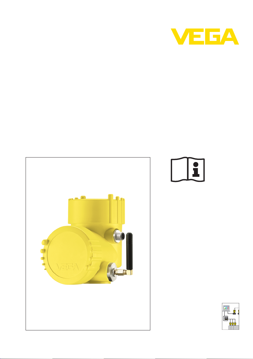
PLICSMOBILE
GSM/GPRS radio module
Document ID:
36849
conditioning instruments
and communication
Signal
Page 2

1 Contents
Contents
1 Product description
1.1 Structure . . . . . . . . . . . . . . . . . . . . . . . . . . . . . . . . .
1.2 Principle of operation . . . . . . . . . . . . . . . . . . . . . . . .
1.3 Operation. . . . . . . . . . . . . . . . . . . . . . . . . . . . . . . . .
2 Mounting
2.1 General instructions . . . . . . . . . . . . . . . . . . . . . . . . .
3 Connecting to power supply
3.1 Preparing the connection . . . . . . . . . . . . . . . . . . . . .
3.2 Connection options . . . . . . . . . . . . . . . . . . . . . . . . . .
3.3 Connection steps PLICSMOBILE. . . . . . . . . . . . . . . .
3.4 Connection steps sensor electronics . . . . . . . . . . . . .
3.5 Wiring plan. . . . . . . . . . . . . . . . . . . . . . . . . . . . . . . .
4 Battery operation and power saving mode
4.1 Battery operation . . . . . . . . . . . . . . . . . . . . . . . . . . .
4.2 Battery sizing . . . . . . . . . . . . . . . . . . . . . . . . . . . . . .
4.3 Power saving options . . . . . . . . . . . . . . . . . . . . . . . .
5 Set up
5.1 Adjustment system . . . . . . . . . . . . . . . . . . . . . . . . . .
5.2 Connecting the PC . . . . . . . . . . . . . . . . . . . . . . . . . .
5.3 Parameter adjustment with PACTware . . . . . . . . . . . .
5.4 Mobile network and SIM card . . . . . . . . . . . . . . . . . .
5.5 Internet connection and measured value transmission.
3
4
4
5
6
6
6
8
8
9
9
10
12
12
13
14
16
6 Maintenance and fault rectification
6.1 Maintenance . . . . . . . . . . . . . . . . . . . . . . . . . . . . . .
6.2 Remove interferences . . . . . . . . . . . . . . . . . . . . . . . .
7 Supplement
7.1 Technical data . . . . . . . . . . . . . . . . . . . . . . . . . . . . .
7.2 Industrial property rights . . . . . . . . . . . . . . . . . . . . . .
7.3 Trademark . . . . . . . . . . . . . . . . . . . . . . . . . . . . . . . .
Editing status: 2011-11-16
2 PLICSMOBILE • GSM/GPRS radio module
19
19
22
24
24
36849-EN-111221
Page 3
1
3
4
2
1 Product description
1 Product description
1.1 Structure
Note:
This supplementary instructions manual describes the optionally
available GSM/GPRS radio module PLICMOBILE which is integrated
in the second housing chamber of a plics
manual is a supplement to the respective operating instructions
manual of the sensor and thus cannot be used as a self-contained
operating instructions manual.
®
sensor. This instructions
Scope of delivery
Constituent parts
The scope of delivery encompasses:
l Sensor with mounted PLICSMOBILE
l Antenna (internal or external)
l Mini-USB cable
l Cable gland (included in delivery)
l Documentation
- this operating instructions manual
- if necessary, further certificates
As an option, the GSM/GPRS radio module PLICMOBILE can be
mounted in a plics
®
sensor with double chamber housing (only when
the sensor is thus ordered, retrofitting not possible). The PLICS-
MOBILE is in the side chamber and the sensor electronics is in the
upper chamber of the housing.
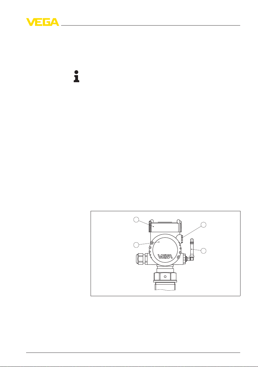
Fig. 1: Sensor with integrated PLICSMOBILE
1 Housing chamber with sensor electronics
2 Housing chamber with PLICSMOBILE electronics
3 Blind stopper (can be replaced by the included cable gland)
4 External antenna (optional)
36849-EN-111221
PLICSMOBILE • GSM/GPRS radio module 3
Page 4

1 Product description
1.2 Principle of operation
Application area
Functional principle
Voltage supply
transmission of measured values and for remote parameter adjustment of plics
®
sensors. Due to the large operating voltage range and
the integrated power saving functions, a mains-independent p ower
supply via battery or solar cells is possible. Typical applications are
measured value transmission from mobile vessels, battery-operated
level measurement and deep well measurement.
The measured value and message transmission can be
optionally carried out via e-mail or SMS. Furthermore the measured
values can be transitted via http to the visualisation software WEB-VV.
The use of the PLICSMOBILE is particularly suitable for inventory
management, VMI (Vendor Managed Inventory) and remote enquiry.
The PLICSMOBILE is a GSM/GPRS radio unit for
integrated in the second housing chamber of a plics
The internal radio unit PLICSMOBILE is
®
sensor. The
measured value recorded by the sensor is transferred via the I²C
interface to the PLICSMOBILE.
The transmission of measured values, event messages and diagnosis
information to the user is carried out via the GSM/GPRS network.
Thanks to quadband technology, the device can be used virtually
anywhere in the world. There is also the option of accessing the
connected sensor via remote parameter adjustment.
The voltage supply is provided via a standard low voltage (external
power supply unit/battery/accumulator). You can find detailed speci-
fications in chapters "Connecting to power supply" and "Technical
data".
If desired, PLICSMOBILE can also power the sensor electronics.
1.3 Operation
The adjustment is made via PACTware and the respective DTM by
using the integrated USB connection.
4 PLICSMOBILE • GSM/GPRS radio module
36849-EN-111221
Page 5

2 Mounting
2 Mounting
2.1 General instructions
Information:
You can find the general mounting instructions in the operating
instructions manual of the respective sensor. The instructions listed
below are a supplement to that part of the radio module.
Mounting position
Check before mounting if there is sufficient coverage (signal strength)
by the chosen mobile phone provider at the planned location. This can
be simply tested with a mobile phone. Make sure the SIM cards in the
PLICSMOBILE and in the mobile phone are from the same mobile
phone provider. If the radio reception is too weak, you should search
for a better position. In closed rooms this would be, for example, close
to a window or at least closer to an outer wall. As an option, an external
antenna with complete confectioned cable is available.
Select a mounting location where the instrument is within easy reach
for mounting and connecting as well as for the connection via USB. To
facilitate mounting, the housing can be rotated by 330° without the use
of any tools.
Note:
During operation, a distance of at least 20 cm should be kept between
the antenna and persons working nearby. Operation of the instrument
with smaller distances is not recommended.
36849-EN-111221
PLICSMOBILE • GSM/GPRS radio module 5
Page 6

3 Connecting to power supply
3 Connecting to power supply
3.1 Preparing the connection
Note:
You can find the general connection instructions in the operating
instructions manual of the respective sensor. The instructions listed
below are a supplement to that part of the radio module.
Keep in mind that when using PLICSMOBILE, no additional external
indication such as e.g. VEGADIS 61 can be connected.
3.2 Connection options
Voltage supply of sensor electronics and PLICSMOBILE can be
carried out in the following two ways:
Common power supply
of sensor electronics
and PLICSMOBILE
Separate power supply
of sensor electronics
and PLICSMOBILE
With this version, only one voltage supply for both electronics modules
is required. The voltage supply is connected to the PLICSMOBILE.
The sensor connection cable transmits, in addition to the measured
value, also the voltage supply of the sensor. Hence there is no
4 … 20 mA or Fieldbus signal from the sensor electronics available for
processing, e.g. via a PLC/control system. Hence, measured value
transmission can be only carried out via radio transmission through email/SMS/WEB-VV. Every sensor with integrated PLICSMOBILE is
shipped in this version.
With this version, the sensor electronics and the PLICSMOBILE are
each powered by a separate voltage supply. The measured values
can be transmitted via radio link and the 4 … 20 mA or Fieldbus signal
is also available for processing, for example via a PLC. If this version is
used, the internal connection cable must be separated and isolated at
the terminals of the sensor electronics. The blind stopper in the upper
housing chamber must be replaced by the included cable gland.
Connection of the sensor power supply is then carried out as
described in the respective operating instructions manual.
3.3 Connection steps PLICSMOBILE
The connection of PLICSMOBILE must be carried out in general
and is independent of the selected connection variant (separate or
common power supply).
Proceed as follows:
1 Unscrew housing cover of the lateral housing chamber
2 Loosen the compression nut of the cable gland on the left
3 Remove approx. 10 cm (4 in) of the cable mantle, strip approx.
1 cm (0.4 in) of insulation from the ends of the individual wires
4 Insert the cable into the cable gland through the cable entry
36849-EN-111221
6 PLICSMOBILE • GSM/GPRS radio module
Page 7
3 Connecting to power supply
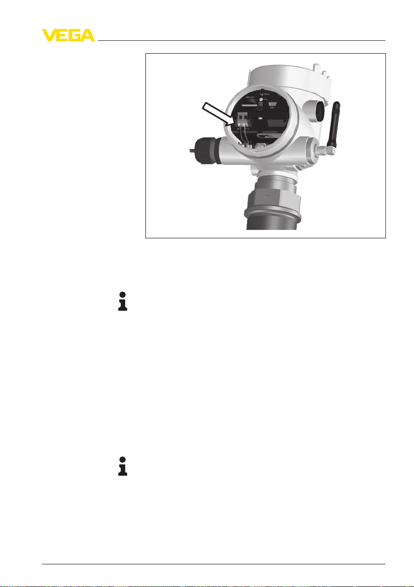
Fig. 2: Connection steps 4 and 5
5 Insert the wire ends into the terminals according to the wiring plan
Information:
Solid cores as well as flexible cores with cable end sleeves are
inserted directly into the terminal openings. In case of flexible cores
without end sleeves, press the terminal head with a small screwdriver;
the terminal opening is freed. When the screwdriver is released, the
terminal closes again.
6 Check the hold of the wires in the terminals by lightly pulling on
them
7 Connect the screen to the internal ground terminal, connect the
outer ground terminal to potential equalisation
8 Tighten the compression nut of the cable entry. The seal ring must
completely encircle the cable
9 Screw the housing cover on
The electrical connection is finished.
Information:
The terminal block is pluggable and can be removed from the
electronics. To do this, lift the terminal block with a small screwdriver
and pull it out. When inserting t he terminal block again, you should
hear it snap in.
36849-EN-111221
PLICSMOBILE • GSM/GPRS radio module 7
Page 8
1
Bus
USB
Status
Test
SIM-Card
1
2
+
( )
(-)
3 Connecting to power supply
Wiring plan PLICSMOBILE
3.4 Connection steps sensor electronics
These steps must only be carried out if the sensor electronics is to be
powered via an additional voltage supply, for example, if the 4 … 20 mA
signal has to be evaluated.
Proceed as follows:
1 Unscrew housing cover of the upper housing chamber
2 Loosen and isolate the internal connection cable from the
terminals
3 Remove the blind stopper of the upper housing chamber
4 Insert the cable gland which is included in the delivery
5 Carry out connection as described in the operating instructions
manual of the sensor
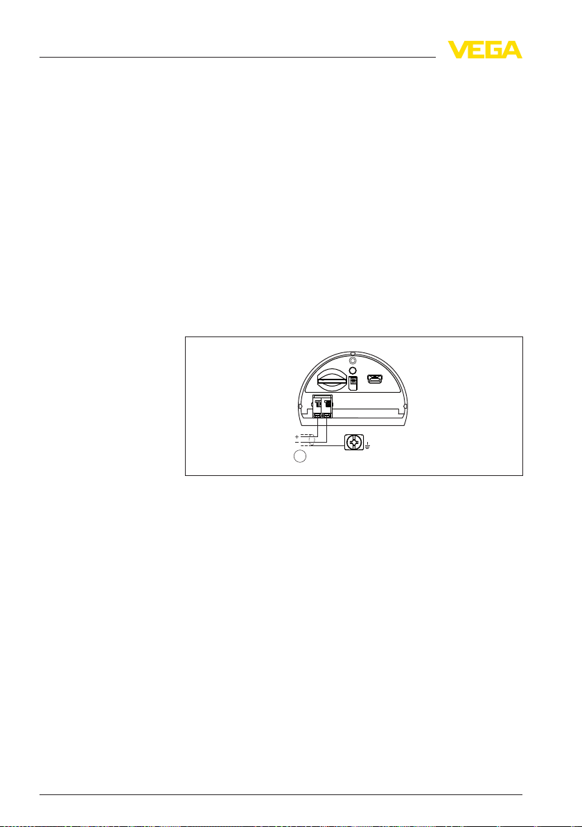
3.5 Wiring plan
Fig. 3: Connection of the PLICSMOBILE supply voltage
1 Voltage supply
8 PLICSMOBILE • GSM/GPRS radio module
36849-EN-111221
Page 9

4 Battery operation and power saving mode
4 Battery operation and power saving mode
4.1 Battery operation
PLICSMOBILE can be also powered via the battery. You can find
If no network-supported voltage supply is available,
detailed specification for voltage supply in chapter "Technical data".
The power saving mode should be switched on in battery operation
and time-controlled measured value transmission and the sensor
should be set to HART multidrop mode to increase the running time
(details se chapter "Power saving options").
4.2 Battery sizing
following points must be observed:
Power consumption in power saving mode:
If a battery or an accumulator is used which cannot be charged
cyclically, then the power saving mode should be activated. With an
operating voltage of e.g. 12 V, a standby power consumption of
0.3 mW must be taken into account. With an assumed lifetime of e.g.
one year, the requirement is approximately 2.6 Wh, which corresponds
to a battery capacity of 0.22 Ah at 12 V. The standby power
consumption with specific operating voltages is stated in the
"Technical data".
Power requirement complete measurement cycle incl. measured
value transmission:
A measurement cycle lasts approximately 60 to 120 seconds
(dependent on sensor type and network quality) and includes
automatic switching on of the sensor (HART multidrop mode with
4 mA), recording of the measured value, measured value transmission
and a return to the power saving mode. During this time, a power of
approximately 20 mWh is required. For example, with one measurement per day, this adds up to approx. 9.6 Wh per year, which
corresponds to a battery capacity of approx. 0.8 Ah at 12 V.
Examples for battery capacitance dependent on the number of
transmission cycles
When selecting an external battery/accumulator, the
Number of messages/day
1 2.6 Wh 9.6 Wh 0.8 Ah
2 2.6 Wh 16.8 Wh 1.4 Ah
36849-EN-111221
PLICSMOBILE • GSM/GPRS radio module 9
Annual consumption PLICSMOBILE
Standby energy
demand
Energy demand
for message
transmission
Required battery capacitance
with 12 V
Page 10

4 Battery operation and power saving mode
Permanent operation
Number of mes-
sages/day
4 2.6 Wh 32.4 Wh 2.7 Ah
8 2.6 Wh 61 Wh 5.1 Ah
24 2.6 Wh 178.8 Wh 14.9 Ah
Annual consumption PLICSMOBILE
Standby energy
demand
Energy demand
for message
transmission
Required battery capacitance
with 12 V
Note:
Due to the nature of the system, each battery and accumulator has a
self-discharge which can vary considerably dependent on the type.
This is very important for the calculation of the required capacitance. In
the listed examples, this self-discharge is not taken into accunt. The
available capacitance depends also considerably from the temperature. The specifications refer to a temperature of 20 °C (68 °F).
4.3 Power saving options
In the DTM (see chapter "Parameter adjustment with PACTware")
you can select under the menu item "Energy options" between the
modes "Permanent operation" and "Power saving mode".
In permanent (non-stop) operation PLICSMOBILE and the sensor
always remain switched on. Only in this mode can the instrument be
used for level monitoring and send an e-mail when a certain level is
reached or an error occurs (measured value/status-controlled transmission). In permanent operation PLICSMOBILE allows remote
parameter adjustment. Configuration changes on PLICSMOBILE as
well as the sensor can thus be carried out remotely from any PC with
PACTware.
Power saving mode
In this mode, the integrated GSM modem as well as a sensor
connected to PLICSMOBILE are switched on automatically if the timecontrolled message transmission is about. After the correct measured
value is recorded, then the login into the GSM network is carried out
and the measured value sent. Then return to the power saving mode.
The time for this transaction depends on the connected sensor type
and the network quality and is normally 60 to 120 seconds. A pressure
transmitter for examples receives the measured value earlier than a
radar or ultrasonic sensor.
Note:
Keep in mind that an event-controlled transmission (measured value/
status-controlled) is not possible in the power saving mode.
HART multidrop
With battery operation and a HART sensor with non-required
4 … 20 mA signal, we recommended setting the sensor to multidrop
10 PLICSMOBILE • GSM/GPRS radio module
36849-EN-111221
Page 11

4 Battery operation and power saving mode
mode. In such case, the sensor consumes constantly only 4 mA
independent of the measured level, which can increase battery life
considerably. A description of the activation of multidrop mode can be
found in the operating instructions of the indicating and adjustment
module.
36849-EN-111221
PLICSMOBILE • GSM/GPRS radio module 11
Page 12

4
1
3
2
USB
Status
Test
SIM-Card
5 Set up
5 Set up
5.1 Adjustment system
Setup requirements
Indicating and adjust-
ment elements
A pC with PACTware and respective DTM is required for setup.
The connection is carried out via a standard mini USB cable (in the
scope of delivery). A released SIM card with data transmission option
must be used in PLICSMOBILE. A good network coverage of the u sed
GSM/GPRS network must be available at the place of operation.
Adjustment on the instrument is limited to a test key and an LED. With
these, the operation and the status of the instruments can be checked
(selection of the GSM network, standby …).
Fig. 4: Indicating and adjustment elements
1 SIM card slot
2 Status indication
3 Key to the test operation
4 Mini-USB interface
Information:
The function description of the key and the status indication is
available in chapter "Mobile phone network and SIM card".
5.2 Connecting the PC
Connection of the PC via
USB
12 PLICSMOBILE • GSM/GPRS radio module
The parameter adjustment of PLICSMOBILE is carried out via PC and
USB interface. The required connection is located in the electronics
housing. Keep in mind that proper functioning of the USB interface can
only be guaranteed in the (limited) temperature range of 0 … +60 °C.
If the PC is provided with a Full-Power-USB-Port, the PLICSMOBILE is
powered via the integrated USB power supply. Parameter adjustment
is thus possible without connected power supply, but measured value
recording and transmission is not possible. Power supply via USB is
not possible with a Low-Power-USB-Port.
36849-EN-111221
Page 13

1
3
2
5 Set up
Note:
The connection via USB requires a driver. First of all, install the driver
before connecting PLICSMOBILE to the PC.
The required USB driver is included on the CD "DTM Collection".
You should always use the latest version to ensure support of all
instrument functions. The system requirements for operation correspond to those of the "DTM Collection" or of PA CTware.
During installation of the "DTM Collection", the a ppropriate instrument
driver is installed automatically. When PLICSMOBILE is connected,
the driver installation is completed autonomously and is ready for
operation without a restart.
Fig. 5: Connection of the PC via USB
1 USB interface of the PC
2 Mini-USB connection cable (in the scope of delivery)
3 USB interface of PLICSMOBILE
5.3 Parameter adjustment with PACTware
Prerequisites
36849-EN-111221
PLICSMOBILE • GSM/GPRS radio module 13
For adjustment via PC, the configuration software PACTware
and a suitable instrument driver (DTM) according to FDT standard a re
required. The up-to-date PACTware version as well as all available
DTMs are compiled in a DTM Collection. The DTMs can also be
integrated in other frame applications according to FDT standard.
Note:
To ensure that all instrument functions are supported, you should
always use the latest DTM Collection. Furthermore, not all described
functions are included in older firmware versions. You can download
the latest instrument software from our homepage. A description of the
update procedure is also available in the Internet.
The general software handling is described in the operating
instructions manual "DTM Collection/PACTware" attached to each
DTM Collection and which can also be downloaded from the Internet.
Detailed descriptions are available in the online help of PACTware and
the DTMs.
Page 14

5 Set up
Standard/Full version
version and as a full version that must be purchased. In the standard
All device DTMs are available as a free-of-charge standard
version, all functions for complete setup are already included. An
assistant for simple project configuration simplifies the adjustment
considerably. Saving/printing the project as well as import/export
functions are also part of the standard version.
In the full version there is also an extended print function for
complete project documentation as well as a save function for
measured value and echo curves. In addition, there is a tank
calculation program as well as a multiviewer for display and analysis of
the saved measured value and echo curves.
5.4 Mobile network and SIM card
A released SIM card with data transmission option is
required for setup. Dial-out connections from PLICSMOBILE can be
provided optionally via GPRS (volume-based billing) or via a dial-up
connection (CSD, time-based bill ing). The transmission mode can be
adjusted when configuring via PACTware and DTM. Outgoing
connections are used for transmission of measured values via e -mail/
WEB-VV.
Dial-in connections on PLICSMOBILE are only possible if the SIM
card used supports the data service CSD (Circuit Switched Data).
Dial-in connections are used for remote parameter adjustment. The
use of GPRS is not possible.
Information:
The SIM card does not belong to the scope of delivery of the
instrument and must be provided by the respective operator. To avoid
roaming costs, the card should be bought in the country in which the
PLICSMOBILE is installed and operated.
also via GPRS. The availability of GPRS at the location of
The data transmission can be either carried out via CSD but
PLICSMOBILE depends on the respective mobile network provider.
With CSD, the transmission costs are calculated by means of the
required time. With GPRS, the calculation is made according to the
transmitted data volume. For this, the data transmission should be
always carried out via GPRS, if possible.
When transmitting the measured value via e-mail or WEB-VV,
approximately 5 KB data are transmitted. For example with an hourly
transmission this will cause a monthly net data volume of totally
approximately 4 MB.
Dependent on the selected tariff, the mobile network provider carries
out a so called block rounding. When checking out of the GPRS
network billing units are rounded. Since the PLICSMOBILE checks out
of the GPRS network after transmission of each message provided the
14 PLICSMOBILE • GSM/GPRS radio module
36849-EN-111221
Page 15

5 Set up
energy saving mode is activated, this block rounding is applied with
each transmission. If for example a tariff with a block rounding to
100 KB is used, then an hourly measured value transmission causes a
monthly billing volume of more than 70 MB. Select therefore a pure
data tariff (M2M) with a possibly low block rounding.
Insert SIM card
Insert the card with the beveled side in front into the card slot until it
snaps in. The contact surface must point downward.
Note:
The electronics must be voltage-free when inserting the SIM card. To
ensure this, the entire voltage supply must be switched off. This
includes disconnecting a battery and USB cable that might be
installed. Take ESD protective measures when handling the SIM card.
Electrostatic discharges can damage the SIM card or the PLICSMOBILE.
Fig. 6: Insert SIM card
Activate SIM card
To avoid misuse, the SIM card is generally locked by a PIN. To
ensure that PLICSMOBILE can contact these locked SIM cards, first of
all the PIN must be entered. For this purpose the as sistant "Activate
SIM card" is available in the DTM. Enter here the correct PIN for the
card. The assistant also offers the option of changing the PIN.
Then check if the card is logged into the network and if sufficient
network coverage (signal strength) exists. This can be checked in the
36849-EN-111221
PLICSMOBILE • GSM/GPRS radio module 15
Page 16

5 Set up
DTM menu "Network information" under "Setup - Diagnosis". You can
also see the general device status via the status indication.
Status indication
Internet connection (Di-
al-Out)
The following operating conditions are signalled via the LED
status indication:
l LED does not light: no operating voltage or power saving mode
active
l Constant flashing: Instrument is not logged into the GSM
network
l Unsteady flashing (long OFF/short ON): instrument is booked
into the GSM network
l Continuous light: Transmitting or dia-up connection (via CSD)
active
When PLICSMOBILE is in power saving mode, a login procedure can
be triggered via the test key. The user can thus check via the status
LED if logging into the GSM network is possible.
5.5 Internet connection and measured value
transmission
The transmission of measured values via e-mail or to the
visualization software WEB-VV is always based on an Internet
connection. Access data (user name/password) are required for this
connection. With a GSM connection also a dial-in number is required,
with a GPRS connection the APN (Access Point Name) must be
stated. You can get this information from your mobile phone provider.
You can find further information and a list of the standard mobile phone
providers with their access data in the Online help of the PLICS-
MOBILE DTM.
16 PLICSMOBILE • GSM/GPRS radio module
36849-EN-111221
Page 17

Fig. 7: Input of the Internet access data
5 Set up
Measured value transmission
following ways:
l Via intergrated mail client to any e-mail address
l Via SMS to any mobile phone
l Via http to the visualization software WEB-VV
The measured values can be transmitted optionally in the
To establish the measured value transmission, a comfortable assistant
is available under the DTM menu item "Event list". The measured
values can be transmitted at individually definable times or intervals.
Also a message can be triggered when exceeding or falling below a
certain level. Furthermore a measured value transmission can be
carried out status-controlled, for example in case of a fault signal.
E-mail transmission
For this option, an e-mail account with name of the inbox and outbox
server (POP3/SMTP) as well as the user name/password are required
for authentication. These specifications are available from your e-mail
provider. You can find further information in the Online help of the
PLICSMOBILE DTM.
The measured values can be optionally sent directly in the e-mal or in
an attachment. The formats TXT, CSV, HTML or XML are available.
36849-EN-111221
PLICSMOBILE • GSM/GPRS radio module 17
Page 18

5 Set up
Fig. 8: Input of the e-mail access data
SMS transmission
For measured value transmission via SMS, no furterh access data are
required because all specifications are already available via the mobile
phone contract.
WEB-VV
For the configuration, only the URL or the IP address of the WEB-VV
server are required. When the hosting is made via VEGA, then the
server is contacted via the URL: "web-vv.vega.com". If WEB-VV is
hosted in your company, then you will get the URL from the IT
department.
Remote parameter adjustment (Dial-In)
The setup of PLICSMOBILE and sensor is carried out via USB and
a PC with PACTware and corresponding DTM. With a SIM card with
activated CSD service, access via the radio link is also possible
(remote parameter adjustment). Keep in mind that this is carried out
via a dial-in connection, which bases invoicing on connection time.
Considerable connection costs can be incurred depending on the
duration of use.
18 PLICSMOBILE • GSM/GPRS radio module
36849-EN-111221
Page 19

6 Maintenance and fault rectification
6 Maintenance and fault rectification
6.1 Maintenance
If the instrument is used properly, no special maintenance is required
in normal operation.
6.2 Remove interferences
Reaction when malfunc-
tions occur
Failure reasons
Fault rectification
24 hour service hotline
Error messages
The operator of t he system is responsible for taking suitable measures
to rectify faults.
A maximum of reliability is ensured. Nevertheless, faults can occur
during operation. These may be caused by the following, e.g.:
l Measured value from sensor not correct
l Voltage supply
l Interference on the cables
The first measures to be taken are to check the input/output signals
as well as to evaluate the error messages via the DTM. The procedure
is described below. In many cases, the causes can be determined in
this way and faults can be rectified.
Should these measures not be successful, please call in urgent
cases the VEGA service hotline under the phone no. +49 1805 858550.
The hotline is available to you 7 days a week round-the-clock. Since
we offer this service world-wide, the support is only available in the
English language. The service is free of charge, only the standard
telephone costs will be charged.
? No indication of the signal strength
l No GSM network available
à Check network availability via mobile phone
? E008
l Sensor not found
à Check connection of the sensor
? E013
l Sensor signals failure, no valid measured value
à Check sensor parameter adjustment
à Send sensor for repair
36849-EN-111221
PLICSMOBILE • GSM/GPRS radio module 19
Page 20

6 Maintenance and fault rectification
? E030
l Sensor in boot phase
l value not valid
à Check sensor parameter adjustment
? E034
l EEPROM CRC error
à Switch the instrument off and on
à Carry out a reset
à Send instrument for repair
? E035
l ROM CRC error
à Switch the instrument off and on
à Carry out a reset
à Send instrument for repair
? E036
l Instrument software not executable (during software update or
à Wait until software update is finished
à Carry out another software update
after failed update)
? E042
l Hardware error with selfcheck
à Send instrument for repair
? E053
l Sensor measuring range not read correctly
à Communication error: Check sensor cable and screening
? E086
l Error communication hardware (initialisation of the radio
module failed)
à Initialisation is carried out automatically. If the error exists
permanently, send instrument for repair
20 PLICSMOBILE • GSM/GPRS radio module
36849-EN-111221
Page 21

6 Maintenance and fault rectification
Reaction after fault rectification
Depending on the reason for the f ault and the measures taken, the
steps described in chapter "Set up" may have to be carried out again.
36849-EN-111221
PLICSMOBILE • GSM/GPRS radio module 21
Page 22

7 Supplement
7 Supplement
7.1 Technical data
Voltage supply
Operating voltage
Power consumption
- Power saving mode (9 V/12 V) 0.18 mW/0.3 mW
- Power saving mode (24 V/32 V) 1.8 mW/3.7 mW
- Permanent operation 1.1 W
- Peak power (measured value
transmission)
Power requirement
- Measurement cycle incl. transmis-
sion
Radio transmission
Radio frequency Quadband GSM (850/900/1800/1900 MHz)
Antenna connection SMA socket
Antenna version Isotropic (Omni) antenna
1)
2)
8 … 32 V DC
5.1 W
3)
20 mWh
USB interface
4)
Quantity 1 x in the lateral housing chamber
Plug connection Mini-B (4-pole)
USB specification 2.0 (Fullspeed)
Max. cable length 5 m (196 in)
Ambient conditions
Ambient temperature
- Instrument in general -25 … +60 °C (-13 … +140 °F)
- USB interface 0 … +60 °C (+32 … +140 °F)
Storage and transport temperature -25 … +80 °C (-13 … +176 °F)
Radio approvals
Radio approvals of the integrated GSM modem
- FCC ID RI7GE865
- IC (Industry Canada) 5131 A -GE865
1)
When the instrument is powered by an external voltage supply, make sure
the voltage supply has a sufficient current carrying capacity. With a voltage
supply <9.6 V, current peaks of up to 2 A must be expected.
2)
The listed power specifications include the voltage supply of a HART sensor
with 20 mA
3)
The listed energy demand includes the voltage supply of a HART sensor
(VEGAPULS 61with 4 mA (multidrop mode) and 12 V operating voltage
4)
Limited temperature range, see ambient conditions
22 PLICSMOBILE • GSM/GPRS radio module
36849-EN-111221
Page 23

7 Supplement
Approvals
Instruments with approvals can have different technical data depending on the version.
That's why the associated approval documents have to be noted with these instruments. They are
part of the delivery or can be downloaded under www.vega.com via "VEGA Tools" and "serial
number search" as well as via "Downloads" and "Approvals".
36849-EN-111221
PLICSMOBILE • GSM/GPRS radio module 23
Page 24

7 Supplement
7.2 Industrial property rights
VEGA product lines are global protected by industrial property rights.
Further information see http://www.vega.com.
Only in U.S.A.: Further information see patent label at the sensor housing.
VEGA Produktfamilien sind weltweit geschützt durch gewerbliche Schutzrechte.
Nähere Informationen unter http://www.vega.com.
Les lignes de produits VEGA sont globalement protégées par des droits de
propriété intellectuelle.
Pour plus d'informations, on pourra se référer au site http://www.vega.com.
VEGA lineas de productos están protegidas por los derechos en el campo de la
propiedad industrial.
Para mayor información revise la pagina web http://www.vega.com.
Линии продукции фирмы ВЕГА защищаются по всему миру правами на
интеллектуальную собственность.
Дальнейшую информацию смотрите на сайте http://www.vega.com.
VEGA系列产品在全球享有知识产权保护。
进一步信息请参见网站<http://www.vega.com>。
7.3 Trademark
All the brands as well as trade and company names used are property
of their lawful proprietor/originator.
24 PLICSMOBILE • GSM/GPRS radio module
36849-EN-111221
Page 25

INDEX
Index
A
Access data 16-17
Accumulator 9
Accumulator capacity 9
Adjustment 13
APN 16
Application area 4
B
Battery 4, 9
Battery capactiy 9
Block rounding 14
C
Connection procedure 8
Connection steps 6
Connection technology 6 , 8
CSD 14, 16
D
Dial-In 14, 18
Dial-in number 16
Dial-Out 14, 16
Dial-up connection 14
Driver 13
DTM 4, 12-14
- DTM Collection 13
- Full version 14
- Standard version 14
E
E-mail 4, 17
Energy options 10
F
Failure - Reasons 19
Fault - Rectification 19
FDT 13
G
GPRS 4, 14, 16
GSM 4
H
HART 10
Hotline 19
I
I²C interface 4
Indication of the signal strength 19
L
LED displays 16
M
M2M 14
Measured value transmission 9-10, 17
Mounting 5
Mounting options 17
Multidrop 10
Multiviewer 14
N
Network coverage 15
O
Online help 13
P
PACTware 4, 12-13
PIN 15
Power saving function 4
Power saving mode 9-10, 14
Power supply unit 9
Q
Quadband 4
R
Remote parameter adjustment 4, 10, 14, 18
Roaming 14
S
Self-discharge 9
Service hotline 19
Signal strength 15
SIM card 14-15
SMS 4
Software update 13
Standby 9
Status indications 16
T
Tank calculation 14
36849-EN-111221
PLICSMOBILE • GSM/GPRS radio module 25
Page 26

Index
U
USB 4, 12
USB cable 12
V
Visualisation 4
VMI 4
W
WEB-VV 4, 17
26 PLICSMOBILE • GSM/GPRS radio module
36849-EN-111221
Page 27

Index
36849-EN-111221
PLICSMOBILE • GSM/GPRS radio module 27
Page 28

VEGA Grieshaber KG
ISO 9001
Am Hohenstein 113
77761 Schiltach
Germany
Phone +49 7836 50-0
Fax +49 7836 50-201
E-mail: info.de@vega.com
www.vega.com
Printing date:
All statements concerning scope of delivery, application,
practical use and operating conditions of the sensors and
processing systems correspond to the information avail-
able at the time of printing.
© VEGA Grieshaber KG, Schiltach/Germany 2011
Subject to change without prior notice 36849-EN-111221
 Loading...