


WRM-10P and WRM-40
TRANSFORMER WINDING RESISTANCE METERS
USER’S MANUAL
Vanguard Instruments Company, Inc.
1520 S. Hellman Ave.
Ontario, California 91761, USA
TEL: (909) 923-9390 |
November 2009 |
FAX: (909) 923-9391 |
Revision 3 |
|
|

WRM-10P AND WRM-40 USER’S MANUAL REV 3
SAFETY SUMMARY
NOTICE
This manual applies to both the WRM-10P and WRM-40 transformer winding resistance meters. The operating procedures are virtually the same for both models, and any differences are clearly described where applicable.
FOLLOW EXACT OPERATING PROCEDURES
Any deviation from the procedures described in this User’s Manual may create one or more safety hazards, may damage the WRM-10P/40, damage the test transformer, or cause errors in the test results. Vanguard Instruments Company, Inc. assumes no liability for unsafe or improper use of the WRM-10P/40.
All safety precautions provided in this manual must be observed during all phases of testing including test preparation, test lead connection, actual testing, and test lead disconnection.
SAFETY WARNING AND CAUTIONS
The WRM-10P/40 shall be used only by trained operators. All transformers under test shall be off-line and fully isolated.
DO NOT MODIFY TEST EQUIPMENT
To avoid the risk of introducing additional or unknown hazards, do not install substitute parts or perform any unauthorized modification to any WRM-10P/40 test unit. To ensure that all designed safety features are maintained, it is highly recommended that repairs be performed only by Vanguard Instruments Company factory personnel or by an authorized repair service provider. Unauthorized modifications can cause safety hazards and will void the manufacturer’s warranty.
WARNING
Do not remove test leads during a test. Failure to heed this warning can result in lethal electrical shock to personnel and damage to the equipment.
i

REV 3 WRM-10P AND WRM-40 USER’S MANUAL
TABLE OF CONTENTS
CONVENTIONS USED IN THIS DOCUMENT ..................................................................................... |
1 |
||
1.0 |
INTRODUCTION.................................................................................................................... |
2 |
|
1.1 |
General Description and Features ................................................................................... |
2 |
|
1.2 |
Technical Specifications ................................................................................................... |
4 |
|
1.2.1. |
WRM-10P Technical Specifications .......................................................................... |
4 |
|
1.2.2. |
WRM-40 Technical Specifications ............................................................................ |
5 |
|
1.3 |
WRM Controls and Indicators.......................................................................................... |
6 |
|
2.0 |
PRE-TEST SETUP ................................................................................................................. |
10 |
|
2.1 |
Operating Voltages ........................................................................................................ |
10 |
|
2.2 |
LCD Screen Contrast Control.......................................................................................... |
12 |
|
2.3 |
Printer Paper Control..................................................................................................... |
12 |
|
2.4 |
Printer Paper.................................................................................................................. |
12 |
|
2.5 |
Replacing the Thermal Printer Paper............................................................................. |
13 |
|
3.0 |
OPERATING PROCEDURES ................................................................................................. |
14 |
|
3.1 |
WRM Cable Connections ............................................................................................... |
14 |
|
3.2 |
General Procedures ....................................................................................................... |
16 |
|
3.3 |
Entering Test Record Header Information..................................................................... |
17 |
|
3.4 |
Performing a Resistance Test......................................................................................... |
20 |
|
3.5 |
Performing a Load Tap Changer / Voltage Regulator Resistance Test .......................... |
29 |
|
3.6 |
Performing a Special Resistance Test ............................................................................ |
36 |
|
3.7 |
Performing a Transient Test .......................................................................................... |
41 |
|
3.8 |
Performing a Diagnostic Test......................................................................................... |
44 |
|
3.9 |
Working with Test Records............................................................................................ |
45 |
|
3.9.1. Restoring a Test Record for Review or Printing ..................................................... |
45 |
||
3.9.2. Reviewing or Printing a Restored Test Record....................................................... |
48 |
||
3.9.3. Printing a Test Record Directory ............................................................................ |
49 |
||
3.9.4. |
Erasing Test Records............................................................................................... |
51 |
|
3.10 Enabling the Computer Interface .................................................................................. |
53 |
||
3.11 Setting the Date and Time ............................................................................................. |
54 |
||
4.0 |
WRM-10P/40 SPECIAL FEATURES ...................................................................................... |
55 |
|
4.1 |
Bypassing Resistance Reading Delay ............................................................................. |
55 |
|
4.2 |
Converting Resistance Measurements .......................................................................... |
56 |
|
5.0 |
Troubleshooting Guide ...................................................................................................... |
57 |
|
ii

|
WRM-10P AND WRM-40 USER’S MANUAL |
REV 3 |
|
LIST OF FIGURES |
|
Figure 1. WRM-10P Controls and Indicators .................................................................................. |
6 |
|
Figure 2. WRM-40 Controls and Indicators .................................................................................... |
8 |
|
Figure 3. 100 – 120 Vac Jumper Settings ...................................................................................... |
10 |
|
Figure 4. 200 – 240 Vac Jumper Settings ...................................................................................... |
10 |
|
Figure 5. WRM-10P Relay Location............................................................................................... |
11 |
|
Figure 6. WRM-40 Relay Location................................................................................................. |
11 |
|
Figure 7. Typical WRM Connections Diagram #1.......................................................................... |
14 |
|
Figure 8. Typical WRM Connections Diagram #2.......................................................................... |
14 |
|
Figure 9. Typical WRM Connections Diagram #3.......................................................................... |
15 |
|
Figure 10. Typical WRM Connections Diagram #4........................................................................ |
15 |
|
Figure 11. Typical V1 Test Report Printout ................................................................................... |
26 |
|
Figure 12. Typical V1 and V2 Test Report Printout....................................................................... |
27 |
|
Figure 13. Typical V1 and V2 Test Report Printout with Multiple Readings ................................ |
28 |
|
Figure 14. |
Typical LTC/Voltage Regulator Test Report Printout................................................... |
35 |
Figure 15. |
Typical Five Minute Special Test Report Printout........................................................ |
40 |
Figure 16. |
Typical Transient Test Report ...................................................................................... |
43 |
Figure 17. |
Typical Test Record Directory Printout........................................................................ |
50 |
|
LIST OF TABLES |
|
Table 1. WRM-10P Technical Specifications................................................................................... |
4 |
|
Table 2. |
WRM-40 Technical Specifications ..................................................................................... |
5 |
Table 3. |
Functional Descriptions of WRM-10P Controls and Indicators ........................................ |
7 |
Table 4. |
Functional Descriptions of WRM-40 Controls and Indicators .......................................... |
9 |
Table 5. |
Voltage Selection Jumper Settings.................................................................................. |
10 |
iii
REV 3 WRM-10P AND WRM-40 USER’S MANUAL
CONVENTIONS USED IN THIS DOCUMENT
This document uses the following conventions:
•Both the WRM-10P and WRM-40 are simply referred to as “WRM” in this manual. The exact model number is used only in cases where differences between the units are discussed.
•A key, switch, or knob on the WRM is indicated as [KEY], [SWITCH], [KNOB].
•Menu names are referenced as “MENU NAME”
•WRM LCD screen output is shown as:
1.OPTION 1
2.OPTION 2
3.OPTION 3
4.OPTION 4
•Warning messages are indicated as:
Warning message
WARNING
•Important notes are indicated as:
Note details
NOTE
1

WRM-10P AND WRM-40 USER’S MANUAL REV 3
1.0INTRODUCTION
1.1General Description and Features
The WRM-10P is designed to accurately measure the winding resistance of highly inductive power transformers. The unit’s dual resistance-reading input channels can measure two winding resistances simultaneously, and four-wire (Kelvin) connections provide high accuracy and require no lead compensation. The WRM-10P provides stable resistance readings of very large transformers by utilizing a 36 Vdc power supply capable of outputting up to 10 Amperes. The resistance reading of a 100MVA transformer can be achieved in 5 minutes or less. The unit’s power supply is cooled by heavy-duty fans designed for continuous operation. For greater flexibility in the field, the WRM-10P comes with a built-in 2.5-inch wide thermal printer used for printing test reports.
Since the WRM-10P can accurately measure resistances ranging from 1 micro-ohm to 2,000 ohms, it can also be used to measure EHV circuit-breaker contact resistance, motor winding resistance, or any low resistance. If the transformer winding temperature is entered, the WRM10P can calculate the equivalent resistance value of the winding material (aluminum or copper) at any standard reference temperature. Also, a special test mode can run a test for up to 45 minutes while saving resistance readings at one-minute intervals. In addition to measuring the resistance value, the WRM-10P also checks the “make-before-break” tap-switching sequences of voltage regulators and load tap changers.
The WRM-10P can store test results in Flash EEPROM. Test results can be printed on the built-in 2.5-inch wide thermal printer or can be transferred to a PC via the RS-232C interface port.
The WRM-40 has all the features of the WRM-10P, but is capable of outputting up to 40 Amperes. The WRM-10P has a resistance reading range of 1 micro-ohm to 2,000 ohms while the WRM-40 has a resistance reading range of 1 micro-ohm to 500 ohms.
The WRM-10P and WRM-40 come furnished with three 50-foot test cables. Each test cable lead is terminated with a quick-disconnect test clip.
Built-in Safety Features
At the end of each test, the WRM automatically dissipates the stored energy in the transformer. This discharge circuit will continue to work even if the supply voltage is lost. For added safety, the unit’s power supply is thermally protected from over-load damage.
User Interface
The WRM features a back-lit LCD screen (20 characters by 4 lines) that is viewable in both bright sunlight and low-light levels. A rugged, alpha-numeric, membrane keypad is used to control the unit.
2

REV 3 WRM-10P AND WRM-40 USER’S MANUAL
Internal Test Record Storage
The WRM can store 63 test records (up to 48 readings per test record) in Flash EEPROM. Test records can be retrieved and printed on the built-in thermal printer or can be transferred to a PC via the RS-232C interface port. A Windows® XP/Vista-based software application is provided with each WRM. This software can be used to retrieve test records from the WRM and can also be used to export records in Microsoft® Excel format.
3

WRM-10P AND WRM-40 USER’S MANUAL REV 3
1.2Technical Specifications
1.2.1. WRM-10P Technical Specifications
Table 1. WRM-10P Technical Specifications
TYPE |
Portable transformer winding resistance meter |
PHYSICAL SPECIFICATIONS |
16.8”W x 12.6”H x 10.6”D (42.6 cm x 32.0 cm x 26.9 cm); Weight: 27 lbs |
|
(12.2 kg) |
INPUT POWER |
100 – 120 Vac or 200 – 240 Vac (factory pre-set), 50/60 Hz |
|
(Please see the voltage setting notes in section 2.1) |
RESISTANCE READING |
1 micro-ohm – 2,000 ohms |
RANGE |
|
ACCURACY |
1 – 19,999 micro-ohms: ±0.5% reading, ±1 count; |
|
20 – 999 milliohms: ±1% reading, ±1 count; |
|
1 – 2,000 ohms: ±1.5% reading, ±1 count |
TEST VOLTAGE |
36 Vdc max |
TEST CURRENT RANGE |
Auto range, 10 Amperes max |
DISPLAY |
Back-lit LCD Screen (20 characters by 4 lines); viewable in bright sunlight |
|
and low-light levels |
PRINTER |
2.5-inch wide built-in thermal printer |
KEYPAD |
Rugged membrane keypad (10 alpha-numeric keys, 6 function keys) |
|
|
INTERNAL TEST RECORD |
Stores 63 test records of 48 readings each |
STORAGE |
|
COMPUTER INTERFACE |
One RS-232C (19,200 Baud) port |
PC SOFTWARE |
Windows® XP/Vista-based software is included with purchase price |
SAFETY |
Designed to meet IEC61010 (1995), UL61010A-1, CSA-C22.2 standards |
|
|
ENVIRONMENT |
Operating: -10˚C to 50˚ C (15˚F to +122˚ F); Storage: -30˚ C to 70˚ C (- |
|
22˚F to +158˚ F) |
CABLES |
Three 50-foot test cables, ground cable, power cord and cable bag |
OPTIONS |
Transportation case |
WARRANTY |
One year on parts and labor |
|
|
The above specifications are valid at nominal operating voltage and at a temperature of 25°C (77°F). Specifications may change without prior notice.
NOTE
4

REV 3 WRM-10P AND WRM-40 USER’S MANUAL
1.2.2. WRM-40 Technical Specifications
Table 2. WRM-40 Technical Specifications
TYPE |
Portable transformer winding resistance meter |
PHYSICAL SPECIFICATIONS |
25”W x 8.5”H x 20”D (63.5 cm x 21.6 cm x 50 cm); Weight: 44 lbs (20 kg) |
INPUT POWER |
100 – 120 Vac or 200 – 240 Vac (factory pre-set), 50/60 Hz |
|
(Please see the voltage setting notes in section 2.1) |
RESISTANCE READING |
1 micro-ohm – 500 ohms |
RANGE |
|
ACCURACY |
1 – 19,999 micro-ohms: ±0.5% reading, ±1 count; |
|
20 – 999 milliohms: ±1% reading, ±1 count; |
|
1 – 500 ohms: ±1.5% reading, ±1 count |
TEST VOLTAGE |
36 Vdc max |
|
|
TEST CURRENT RANGE |
Auto range, 40 Amperes max |
DISPLAY |
Back-lit LCD Screen (20 characters by 4 lines); viewable in bright sunlight |
|
and low-light levels |
PRINTER |
2.5-inch wide built-in thermal printer |
KEYPAD |
Rugged membrane keypad (10 alpha-numeric keys, 6 function keys) |
INTERNAL TEST RECORD |
Stores 63 test records of 48 readings each |
STORAGE |
|
COMPUTER INTERFACE |
One RS-232C (19,200 Baud) port |
PC SOFTWARE |
Windows® XP/Vista-based software is included with purchase price |
SAFETY |
Designed to meet IEC61010 (1995), UL61010A-1, CSA-C22.2 standards |
ENVIRONMENT |
Operating: -10˚C to 50˚ C (15˚F to +122˚ F); Storage: -30˚ C to 70˚ C (- |
|
22˚F to +158˚ F) |
CABLES |
Three 50-foot test cables, ground cable, power cord and cable bag |
OPTIONS |
Transportation case |
WARRANTY |
One year on parts and labor |
The above specifications are valid at nominal operating voltage and at a temperature of 25°C (77°F). Specifications may change without prior notice.
NOTE
5
WRM-10P AND WRM-40 USER’S MANUAL REV 3
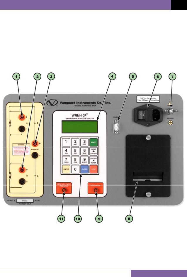
1.3WRM Controls and Indicators
The WRM-10P and WRM-40’s controls and indicators are shown in Figure 1 and Figure 2, respectively. A leader line with an index number points to each control and indicator, which is cross-referenced to a functional description in Table 3 for the WRM-10P and Table 4 for the WRM-40. The tables describe the function of each item on the control panel. The purpose of the controls and indicators may seem obvious, but users should become familiar with them before using the WRM. Accidental misuse of the controls will usually cause no serious harm. Users should also be familiar with the safety summary found on the front page of this User’s Manual.
Figure 1. WRM-10P Controls and Indicators
6
REV 3 WRM-10P AND WRM-40 USER’S MANUAL
Table 3. Functional Descriptions of WRM-10P Controls and Indicators
Item |
Panel Markings |
Functional Description |
Number |
1V1
2V2
3CURRENT
4
Voltage sensing channel #1. Female test connector jacks for connecting voltage-sensing test leads.
Voltage sensing channel #2. Female test connector jacks for connecting voltage-sensing test leads.
Current Output. Female test connector jacks for connecting current test leads.
Back-lit LCD screen (4 lines by 20 characters). Visible in bright light and lowlight conditions.
9-pin RS-232C interface port; female DB type. Data rate is set to 19,200 baud, 1 start bit, 2 stop bits, 8 data bits and no parity bit.
|
|
|
|
Pin |
Signal |
|
|
|
|
|
|
||
5 |
|
RS-232C |
|
2 |
RX |
|
|
|
|
||||
|
|
|
|
|
||
|
|
|
|
3 |
TX |
|
|
|
|
|
|
||
|
|
|
|
5 |
Signal Ground |
|
|
|
|
|
|
||
|
|
|
|
|
|
|
240 Vac 2A,
650-60 Hz Fuse: 250 Vac, 3A Slow Blow
7GROUND
8
9 DISCHARGE
Input power connector with third-wire safety ground. On/Off rocker toggle switch with built-in fuse protection.
Safety ground. This must be connected to station ground before connected the WRM test leads to the transformer.
Built-in 2.5-inch wide thermal printer.
Red LED warning indicator light. This LED is illuminated when the WRM is discharging the stored energy from the transformer. Do NOT disconnect test leads when this light is on. Failure to heed this warning can result in shock to personnel.
10 |
|
|
|
Rugged membrane keypad. |
||
|
11 |
|
HIGH VOLTAGE |
|
Red LED warning indicator light. This LED is illuminated when there is a |
|
|
|
PRESENT |
|
possibility that voltage exists across the test leads. |
|
|
|
|
|
|
|
||
|
|
|
|
|
|
|
7
WRM-10P AND WRM-40 USER’S MANUAL REV 3
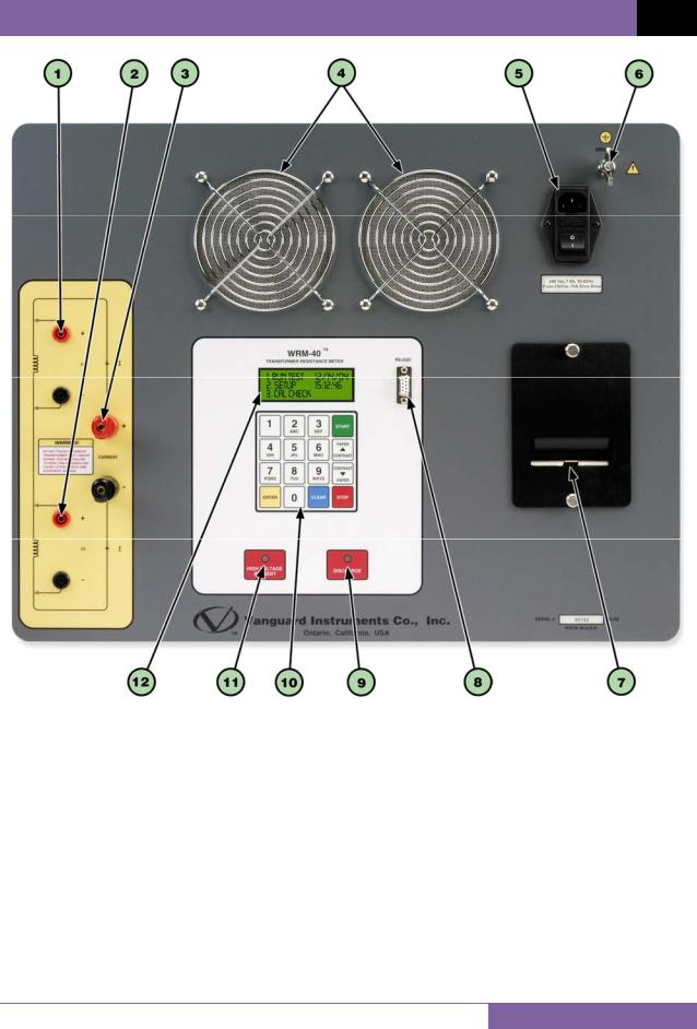
Figure 2. WRM-40 Controls and Indicators
8

REV 3 WRM-10P AND WRM-40 USER’S MANUAL
Table 4. Functional Descriptions of WRM-40 Controls and Indicators
Item |
Panel Markings |
Functional Description |
Number |
1V1
2V2
3CURRENT
4
240 Vac 2A,
5 50-60 Hz
Fuse: 250 Vac,
3A Slow Blow
Voltage sensing channel #1. Female test connector jacks for connecting voltage-sensing test leads.
Voltage sensing channel #2. Female test connector jacks for connecting voltage-sensing test leads.
Current Output. Female test connector jacks for connecting current test leads.
Air intake cooling fans. The air intake cooling fans maintain the internal temperature. There is an output air fan on the side of the case.
Input power connector with third-wire safety ground. On/Off rocker toggle switch with built-in fuse protection.
6GROUND
7
8RS-232C
9DISCHARGE
Safety ground. This must be connected to station ground before connected the WRM test leads to the transformer.
Built-in 2.5-inch wide thermal printer.
9-pin RS-232C interface port; female DB type. Data rate is set to 19,200 baud, 1 start bit, 2 stop bits, 8 data bits and no parity bit.
Pin |
Signal |
2 |
RX |
3 |
TX |
5 |
Signal Ground |
Red LED warning indicator light. This LED is illuminated when the WRM is discharging the stored energy from the transformer. Do NOT disconnect test leads when this light is on. Failure to heed this warning can result in shock to personnel.
10 |
|
|
|
Rugged membrane keypad. |
||
|
11 |
|
HIGH VOLTAGE |
|
Red LED warning indicator light. This LED is illuminated when there is a |
|
|
|
PRESENT |
|
possibility that voltage exists across the test leads. |
|
|
|
|
|
|
|
||
|
|
|
|
|
|
|
|
|
|
|
|
Back-lit LCD screen (4 lines by 20 characters). Visible in bright light and low- |
|
|
12 |
|
|
|||
|
|
|
|
light conditions. |
|
|
|
|
|
|
|
|
|
|
|
|
|
|
|
|
9
WRM-10P AND WRM-40 USER’S MANUAL REV 3
2.0PRE-TEST SETUP
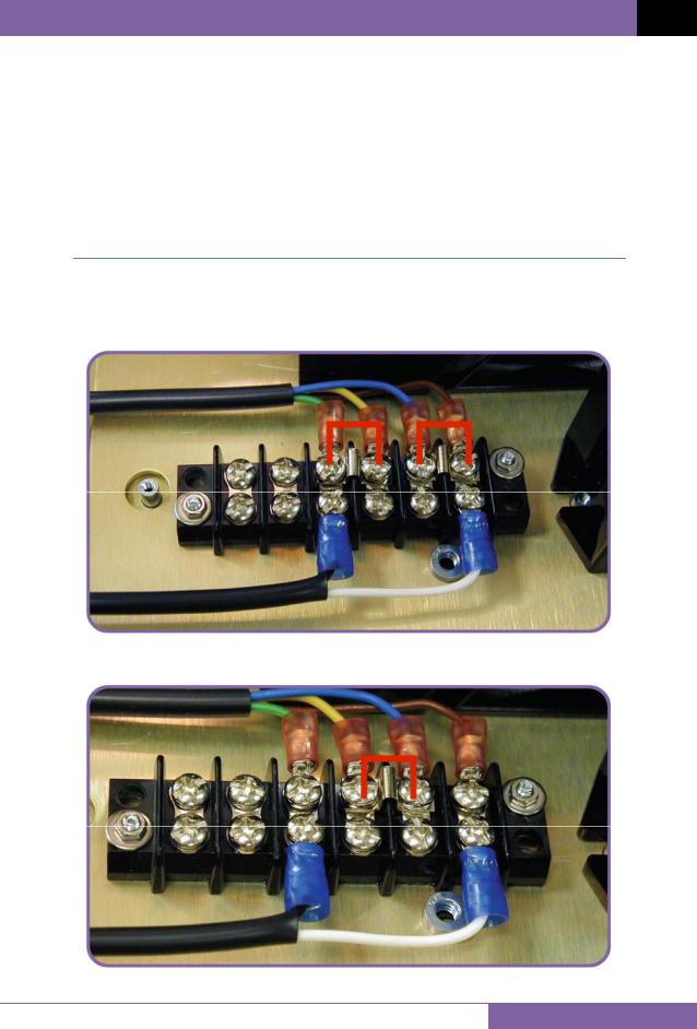
2.1Operating Voltages
The WRM’s operating voltage is preset at the factory and is selectable between 100-120 Vac, 50/60 Hz or 200-240 Vac, 50/60 Hz. The voltage is set by placing jumper(s) on the power terminal block as listed in Table 5 and illustrated in Figure 3 and Figure 4. The relay must also be changed if the voltage settings are changed. Please see Figure 5 and Figure 6 for the location of the relays.
Table 5. Voltage Selection Jumper Settings
|
Voltage |
|
Terminal Block Jumpers |
Relay |
|
|
Selection |
|
Part Number |
||
|
|
|
|
||
|
100 – 120 Vac |
|
Brown to Blue and Yellow to Green |
|
HE2aN-Q-AC120V |
|
200 – 240 Vac |
|
Blue to Yellow |
HE2aN-Q-AC-240V |
|
Figure 3. 100 – 120 Vac Jumper Settings
Figure 4. 200 – 240 Vac Jumper Settings
10

REV 3 WRM-10P AND WRM-40 USER’S MANUAL
Figure 5. WRM-10P Relay Location
Figure 6. WRM-40 Relay Location
11

WRM-10P AND WRM-40 USER’S MANUAL REV 3
2.2LCD Screen Contrast Control
To increase the LCD screen contrast, press and hold the [PAPER Contrast] key for two seconds.
To decrease the LCD screen contrast, press and hold the [PAPER Contrast] key for two seconds.
2.3Printer Paper Control
To advance the WRM printer paper, press and release the [PAPER Contrast] key. To retract the WRM printer paper, press and release the [PAPER Contrast] key.
2.4Printer Paper
The WRM’s built-in thermal printer uses 2.5-inch wide thermal paper for printing test results. To maintain the highest print quality and to avoid paper jams, the use of thermal paper supplied by Vanguard Instruments Company is highly recommended. Additional paper can be ordered from the following sources:
Vanguard Instruments Co, Inc.
1520 S. Hellman Avenue Ontario, CA 91761
Tel: 909-923-9390
Fax: 909-923-9391
Part Number: VIC TP-3 paper
BG Instrument Co.
13607 E. Trent Avenue Spokane, WA 99216 Tel: 509-893-9881 Fax: 509-893-9803
Part Number: VIC TP-3 paper
12

REV 3 WRM-10P AND WRM-40 USER’S MANUAL
2.5Replacing the Thermal Printer Paper
The roll of thermal paper is housed inside a dispenser underneath the printer cover. To replace the paper, follow the steps below:
•Unscrew the two large printer cover screws and remove the printer cover.
•Remove the leftover thermal paper roll from the paper holder.
•Unroll the new thermal paper roll.
•Feed the thermal paper into the slot between the paper pocket and the rubber roller. The printer will automatically pull the paper under the thermal head.
•Place the paper roll into the paper holder.
•Lift the thermal head and align the thermal paper if necessary.
•Re-install the printer cover.
Thermal paper has a chemical coating on one side of the paper. This side should be facing the thermal print head. Incorrect paper loading may result in blank output on
the thermal paper.
NOTE
The thermal paper will show a red stripe to indicate that the roll is about to run out of paper.
13
WRM-10P AND WRM-40 USER’S MANUAL REV 3
3.0OPERATING PROCEDURES
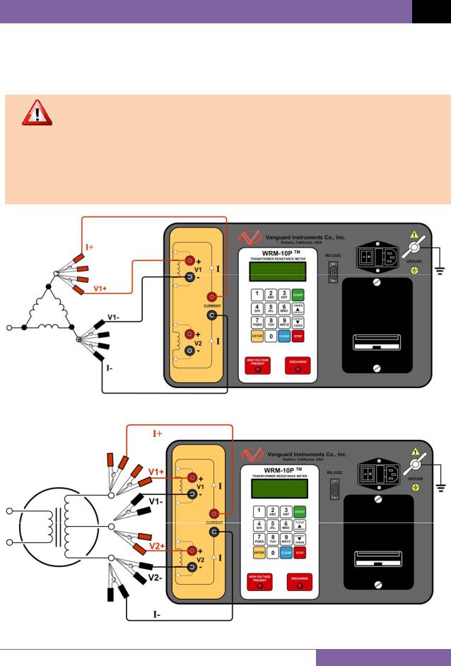
3.1WRM Cable Connections
Typical WRM connection diagrams are shown in Figure 7, Figure 8, Figure 9, and Figure 10.
•Do not touch or disconnect any test lead that is connected to a transformer terminal while high current is being conducted during a test. Failure to heed
WARNINGS |
this warning can result in lethal electric shock to personnel and/or damage |
|
to the equipment. |
•Disconnect the test clips from the transformer bushing only after the WRM has completely discharged the transformer. Always disconnect the test clips slowly from the transformer bushing to prevent an accidental flash-over.
Figure 7. Typical WRM Connections Diagram #1
Figure 8. Typical WRM Connections Diagram #2
14

REV 3 WRM-10P AND WRM-40 USER’S MANUAL
Figure 9. Typical WRM Connections Diagram #3
The above figure illustrates the simultaneous testing of both the high and low windings on a single-phase transformer. When measuring two channels, the above
NOTE cable connection is recommended since it will speed up the testing process.
Figure 10. Typical WRM Connections Diagram #4
15
 Loading...