


VANGUARD CIRCUIT BREAKER ANALYZER – S2
(VCBA S2)
VERSION 4.xx SOFTWARE MANUAL
For Use with Vanguard’s
DigiTMR S2, DigiTMR S2 PC, CT-6500 S2, CT-7000 S2, CT-7500 S2, and CT-8000
Circuit Breaker Analyzers
Vanguard Instruments Company, Inc.
1520 S. Hellman Ave.
Ontario, California 91761, USA
TEL: (909) 923-9390 |
November 2012 |
FAX: (909) 923-9391 |
Revision 3 |
|
|

|
|
|
VCBA S2 VERSION 4.xx SOFTWARE MANUAL |
REV 3 |
|
|
|
|
|
|
|
|
TABLE OF CONTENTS |
|
CONVENTIONS USED IN THIS DOCUMENT ..................................................................................... |
1 |
|||
1.0 |
INTRODUCTION.................................................................................................................... |
2 |
||
1.1 |
|
System Requirements ...................................................................................................... |
2 |
|
2.0 |
SOFTWARE INSTALLATION................................................................................................... |
3 |
||
3.0 STARTING THE VCBA-S2 SOFTWARE.................................................................................... |
6 |
|||
3.1 |
|
The VCBA-S2 Application Workspace............................................................................... |
7 |
|
3.2 |
|
Configuring Default Application Settings ......................................................................... |
9 |
|
3.2.1. Configuring the Communication Parameters ........................................................... |
9 |
|||
3.2.2. Configuring Graph and Overlay Settings................................................................. |
10 |
|||
3.2.3. Configuring Default Report and Export Settings .................................................... |
11 |
|||
3.2.4. Configuring Default Folders and File Locations ...................................................... |
11 |
|||
4.0 WORKING WITH TEST RECORDS ........................................................................................ |
12 |
|||
4.1 |
|
Retrieving Test Records From a CB Analyzer ................................................................. |
12 |
|
4.2 |
|
Opening Test Records From the PC Hard Drive ............................................................. |
14 |
|
4.3 |
|
Analyzing Test Records................................................................................................... |
16 |
|
4.4 |
|
Viewing a Test Record’s Test Plan.................................................................................. |
19 |
|
4.5 |
|
Customizing the Items Displayed on the Graph............................................................. |
21 |
|
4.6 |
|
Customizing the Graph View.......................................................................................... |
22 |
|
4.6.1. |
Customizing Graph Colors....................................................................................... |
22 |
||
4.6.2. Customizing the Graph Style................................................................................... |
24 |
|||
4.7 |
|
Viewing a Graph Expansion............................................................................................ |
29 |
|
4.8 |
|
Manually Calculating the Average Velocity.................................................................... |
31 |
|
4.9 |
|
Manually Overriding Contact Time/Resistor Contact Time or Contact Wipe................ |
34 |
|
4.10 |
Overlaying Two Timing Shots ..................................................................................... |
38 |
||
4.11 |
Viewing the Test Report ............................................................................................. |
40 |
||
4.12 |
Printing Test Reports and Graphs............................................................................... |
41 |
||
4.13 |
Saving Test Records .................................................................................................... |
46 |
||
4.14 |
Merging Test Records................................................................................................. |
47 |
||
4.15 |
Exporting Test Records ............................................................................................... |
49 |
||
4.15.1. |
Setting Export Preferences.................................................................................. |
49 |
||
4.15.2. |
Manually Exporting a Test Record ...................................................................... |
50 |
||
4.16 |
Toggling the Resistor Flag........................................................................................... |
51 |
||
4.17 |
Viewing Raw Shot Data............................................................................................... |
52 |
||
5.0 WORKING WITH TEST PLANS ............................................................................................. |
53 |
|||
5.1 |
|
Saving the Test Plan from a Test Record........................................................................ |
53 |
|
5.2 |
|
Creating a New Circuit Breaker Test Plan ...................................................................... |
56 |
|
5.2.1. |
Shot Information Section........................................................................................ |
57 |
||
5.2.2. |
Contact Analysis Section ......................................................................................... |
57 |
||
5.2.3. |
Travel Analysis Section............................................................................................ |
58 |
||
5.2.4. |
Display Setup Section.............................................................................................. |
61 |
||
5.3 |
|
Modifying an Existing Circuit Breaker Test Plan ............................................................ |
62 |
|
i

REV 3 VCBA S2 VERSION 4.xx SOFTWARE MANUAL |
|
|
5.4 |
Retrieving a Test Plan from a Circuit Breaker Analyzer ................................................. |
64 |
5.5 |
Transferring a Test Plan to a Circuit Breaker Analyzer .................................................. |
65 |
5.6 |
Using a Test Plan for a Timing Test ................................................................................ |
67 |
5.7 |
Converting Doble Test Plans .......................................................................................... |
68 |
6.0 TIMING A CIRCUIT BREAKER USING THE VCBA S2 SOFTWARE.......................................... |
70 |
|
6.1Performing an OPEN, CLOSE, OPEN-CLOSE, CLOSE-OPEN, or OPEN-CLOSE-OPEN test 70
6.2 |
Performing a Static Resistance Test............................................................................... |
74 |
|
6.3 |
Performing a Dynamic Resistance Test (CT-8000 Only)................................................. |
76 |
|
|
|
LIST OF FIGURES |
|
Figure 1. Sample Test Record ....................................................................................................... |
17 |
||
Figure 2. |
Test Plan Parameters ..................................................................................................... |
19 |
|
Figure 3. Graph Showing Contact Channels in Analog (C1) and Digital Format (C2 and C3) ....... |
23 |
||
Figure 4. |
Sample Test Report Printout (Page 1) ........................................................................... |
43 |
|
Figure 5. |
Sample Test Report Printout (Test Plan) ....................................................................... |
44 |
|
Figure 6. |
Sample Test Graph Printout........................................................................................... |
45 |
|
ii
VCBA S2 VERSION 4.xx SOFTWARE MANUAL REV 3
CONVENTIONS USED IN THIS DOCUMENT
This document uses the following conventions:
•Different versions of Microsoft® Windows will be simply referred to as Windows in this manual
•The general term “CB analyzer” used in this manual refers to any of the VCBA S2 compatible Vanguard circuit breaker analyzer models (DigiTMR S2, DigiTMR S2 PC, CT-6500 S2, CT-7000 S2, CT-7500 S2, CT-8000)
•Command Ribbon items are referred to as Item
•Dialog boxes and their elements (buttons, options, etc.) are referred to as “Dialog Box Element”
•PC keyboard keys are referred to as [Key]. Key combinations are shown as [Key]+[Key].
•File locations, directories, and file names are shown as “C:\folder\filename”
•Warning messages are indicated as:
Warning message
WARNING
•Important notes are indicated as:
Note details
NOTE
Microsoft, Windows, Windows XP, Windows Vista, and Windows 7 are either registered trademarks or trademarks of Microsoft Corporation in the United States and/or other countries. All other trademarks are the property of their respective owners.
1

REV 3 VCBA S2 VERSION 4.xx SOFTWARE MANUAL
1.0INTRODUCTION
The Vanguard Circuit Breaker Analyzer S2 (VCBA S2) software is a Windows-based PC software application for use with Vanguard’s DigiTMR S2, DigiTMR S2 PC, CT-6500 S2, CT-7000 S2, CT7500 S2, and CT-8000 circuit breaker analyzers. This software allows users to perform the following tasks:
•Retrieve Timing Records from a CB Analyzer
•Analyze Retrieved Timing Records
•View Test Results in Graphic Format
•Generate Timing Reports
•Create Breaker Test Plans
•Transfer Breaker Test Plans to a CB analyzer
•Export Test Records in PDF, XML, and Excel format
•Control CB analyzers from the PC to perform Timing Tests
1.1System Requirements
The VCBA-S2 software has the following minimum system requirements:
•PC running Microsoft® Windows® XP, Windows® Vista, or Windows 7
•CD-ROM or DVD-ROM drive
•USB or RS-232C (serial) port
2
VCBA S2 VERSION 4.xx SOFTWARE MANUAL REV 3
2.0SOFTWARE INSTALLATION
Follow the steps below to install the VCBA-S2 software on your PC.
1.Insert the installation CD in the PC’s CD or DVD drive.
2.From the Windows Desktop, click on the “Start” button to bring up the Start Menu.
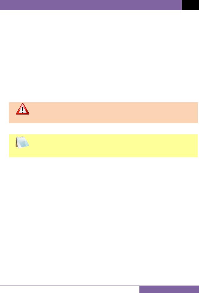
3.From the Start Menu, click on My Computer to open the My Computer window.
4.Double click (or single click in some Windows configurations) on your CD/DVD Drive icon to navigate the installation CD. The contents of the CD will be listed as shown below:
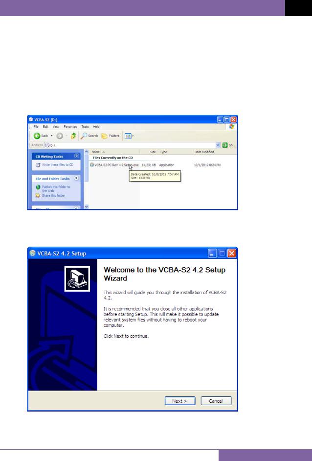
5.Double click (or single click in some Windows configurations) on the “VCBA-S2 PC Rev 4.xx.exe” file to start the installation process. The VCBA-S2 InstallShield Wizard will appear as shown below:
3
REV 3 VCBA S2 VERSION 4.xx SOFTWARE MANUAL
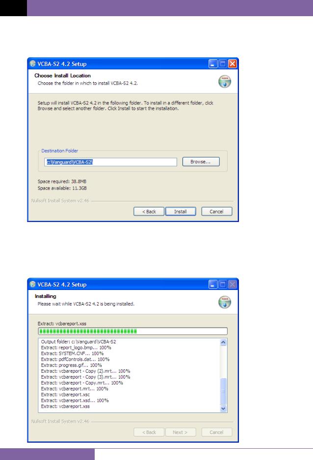
6.Click on the “Next” button to continue. The following screen will be displayed showing the location on your hard drive where the software will be installed (C:\vanguard\VCBAS2):
7.You may choose a different installation location by clicking on the “Browse…” button and then browsing to the location on your hard drive where you would like to install the software. If you would like to install the software in the default location, click on the “Install” button to continue. The following screen will be displayed showing the status of the installation:
4
VCBA S2 VERSION 4.xx SOFTWARE MANUAL REV 3
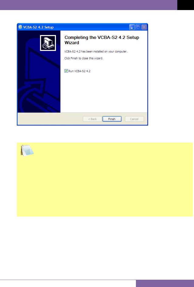
8. The following screen will be displayed once the software has been successfully installed:
9.Click on the “Finish” button to close the InstallShield Wizard and complete the installation process.
•The “Run VCBA-S2 4.x” checkbox will be checked by default. If you leave
|
this box checked, the application will be launched after you click on the |
NOTES |
“Finish” button. |
|
•The installation program will create two sub-folders, “Tests” and “TestPlans”, in the main installation folder. By default all test records will be stored in the “Tests” folder and all test plans will be stored in the “TestPlans” folder.
•The installation program will also install some sample test data files in the “Tests” folder.
•You can later change the default test record and test plan storage locations. Please see section 3.2.4 for details.
5
REV 3 VCBA S2 VERSION 4.xx SOFTWARE MANUAL
3.0STARTING THE VCBA-S2 SOFTWARE
During the installation process, a Vanguard program group will be created under the All Programs submenu in the Windows Start menu. To launch the VCBA-S2 software:
1.Click on the Windows “Start” menu button to open the Start Menu.
2.Click on the All Programs menu item.
3.Click on the Vanguard menu item.
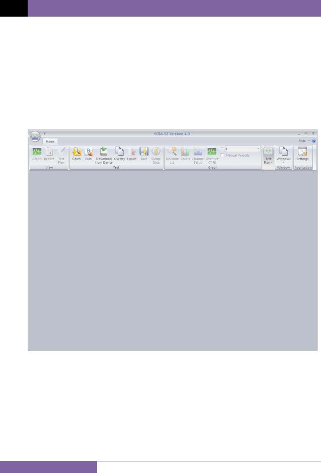
4.Click on the VCBA-S2 menu item. The VCBA-S2 main application window will appear as shown below:
6
VCBA S2 VERSION 4.xx SOFTWARE MANUAL REV 3
3.1The VCBA-S2 Application Workspace
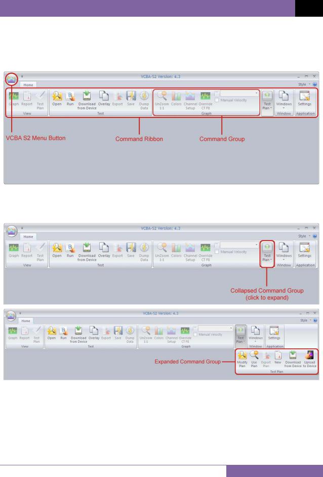
Older versions of the VCBA S2 software used a menu bar and drop-down menus. The current version of the application uses a command ribbon for faster access to all the functions and features of the VCBA S2 software, as shown below:
Related commands are grouped together in the command ribbon. If there is not enough space on the screen, some command groups will be collapsed showing only one item. Click on the command group to view all the commands in that group.
7
REV 3 VCBA S2 VERSION 4.xx SOFTWARE MANUAL
The “File” menu from previous versions has been replaced with the VCBA S2 Menu Button. Click on this button to view the “File” menu options:
8
VCBA S2 VERSION 4.xx SOFTWARE MANUAL REV 3
3.2Configuring Default Application Settings
The VCBA S2 application’s default settings should be configured before attempting to use it for the first time with a Vanguard circuit breaker analyzer. Follow the steps in this section to configure the communication parameters, the graph and overlay display preferences, report and export preferences, and file storage location preferences.
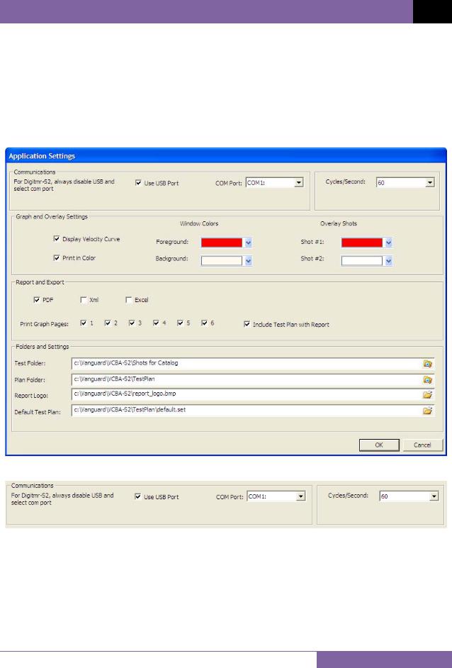
To access the application settings, click on the Settings icon in the Application command group on the command ribbon. The following window will be displayed:
3.2.1. Configuring the Communication Parameters
Follow the steps below to configure the VCBA S2 software so that it can properly communicate with the connected Vanguard circuit breaker analyzer:
1.If the CB Analyzer will be connected via RS-232C, click on the “COM Port:” drop down list and select the COM: port that the CB analyzer is connected to. Make sure the “Use USB Port” checkbox is un-checked.
If the CB Analyzer will be connected via USB, check the “Use USB Port:” checkbox, if not already checked, to enable the USB interface.
9
REV 3 VCBA S2 VERSION 4.xx SOFTWARE MANUAL
Select the preferred frequency from the “Cycles/Second” drop-down menu.
Click on the “OK” button to save your settings.
2.Connect the CB analyzer to the PC via the RS-232C or USB port and turn on the power. The VCBA-S2 software will automatically enable the Computer Interface Mode and connect to the CB analyzer. When the software communicates with the CB analyzer (for example, when retrieving a test record from the CB analyzer), COMPUTER ITF MODE will be displayed on the CB analyzer’s LCD screen.
If you experience any problems enabling the Computer Interface Mode:
1.Turn off both the PC and the CB analyzer.
2.Connect the CB analyzer to the PC via the RS-232C or USB port.
3.Turn on the computer and run the VCBA-S2 software.
4.Turn on the CB analyzer and wait till the startup sequence is finished. The CB analyzer will be ready to communicate with the VCBA-S2 software.
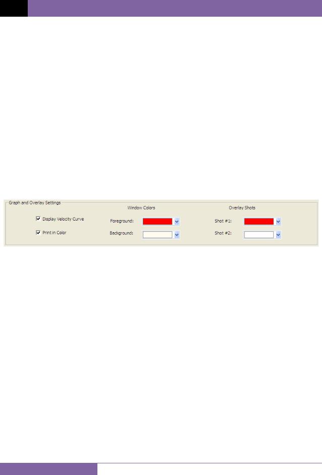
3.2.2. Configuring Graph and Overlay Settings
You can customize the VCBA S2’s window colors and the colors used for overlaying test shots. You can also configure whether the velocity curve is displayed and whether the application should print in color. Use the steps below to configure these settings:
1.If you would like the velocity curve to be displayed on the test results graph, check the “Display Velocity Curve” checkbox (if not already checked) in the “Graph and Overlay Settings” section in the “Application Settings” window. Un-check this box if you do not want to view the velocity curve on the test results graph.
2.If you have a color printer connected to your computer and prefer to print graphs in color, check the “Print in Color” checkbox (if not already checked) in the “Graph and Overlay Settings” section in the “Application Settings” window.
3.To change the Window colors, click on either the “Foreground” or “Background” drop down menu and select the preferred color, respectively.
4.The VCBA S2 software can overlay two test graphs for comparison. You can configure the color used for each graph by clicking on either the “Shot #1” or “Shot #2” dropdown menu and selecting the preferred color for each graph, respectively.
10
VCBA S2 VERSION 4.xx SOFTWARE MANUAL REV 3
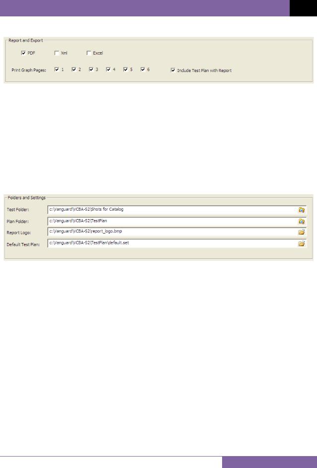
3.2.3. Configuring Default Report and Export Settings
The VCBA S2 software can export test reports in PDF, XML, and Excel formats. Use the steps below to set your report and export preferences:
1.To enable exporting in PDF, XML, and Excel, check the checkbox for each item, respectively.
2.You can export all or selected pages of a test report by checking or un-checking the checkbox next to each page number from the “Print Graph Pages” checkbox group.
3.If you would like the test plan to be exported with the report, check the “Include Test Plan with Report” checkbox.
3.2.4. Configuring Default Folders and File Locations
Follow the steps below to configure default folders and file locations:
1.The “Test Folder” input field shows the current default folder where test shots are stored. You can change this location by clicking on the folder icon on the right and then selecting the folder that you would like to use as the storage location for test shots.
2.The “Plan Folder” input field shows the current default folder where test plans are stored. You can change this location by clicking on the folder icon on the right and then selecting the folder that you would like to use as the storage location for test plans.
3.The VCBA S2 software can display a custom logo image at the top of reports. The “Report Logo” input field shows the name and location of the default logo image file. You can select a different logo image file by clicking on the folder icon on the right and then locating the logo image file that you would like to use.
4.The VCBA S2 software can use a default test plan for performing tests. The default test plan defines color settings for graph elements, default values for analysis points, etc. The “Default Test Plan” input field shows the name and location of the default test plan file. You can select a different default test plan by clicking on the folder icon on the right and then locating the default test plan file that you would like to use.
11
REV 3 VCBA S2 VERSION 4.xx SOFTWARE MANUAL
4.0WORKING WITH TEST RECORDS
The VCBA S2 software can be used to retrieve test records from a CB analyzer or from the PC hard drive. Once a test record is retrieved, you can change the record header information, print the test record, change velocity calculation points, change circuit breaker test parameters, and save the record to the hard drive.
4.1Retrieving Test Records From a CB Analyzer
Follow the steps below to retrieve one or more test records from a connected CB Analyzer:
1.Make sure the VCBA S2 software is running. Connect the CB analyzer to the PC via either the RS-232C or USB port and turn on the power.
2.The CB analyzer should enter Computer Interface Mode. Please see section 3.2.1 for details.
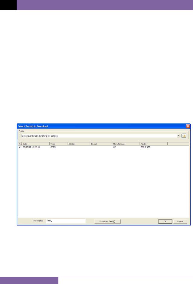
3.Click on the Download from Device icon in the Test command group in the Command Ribbon.
4.The following window will be displayed listing a directory of all the test records stored in the CB Analyzer’s memory:
5.You can select a shot to be retrieved by clicking on the shot number. The selected record will be highlighted. You may select multiple records by holding down the [CTRL] key and clicking on the shot numbers. All selected records will be highlighted. You may de-select a selected record by holding down the [CTRL] key and clicking on the selected shot number a second time.
The “File Prefix” input field allows you to enter a word that will be used as a prefix for the file name for the stored record on the PC hard drive. When a test record is retrieved
12

VCBA S2 VERSION 4.xx SOFTWARE MANUAL REV 3
from a CB analyzer and stored on the hard drive, the file name is in the “n.dat” format, where “n” is the record number.
So if you would like the file name to be “Test_n.DAT”, enter the word “Test_” in the “File Prefix” input field.
6.Click on the “Download Test(s)” button to retrieve the selected test records from the connected CB Analyzer and store them in the default test shot folder. Click on the “OK” button when done retrieving the desired test shots.
13
REV 3 VCBA S2 VERSION 4.xx SOFTWARE MANUAL
4.2Opening Test Records From the PC Hard Drive
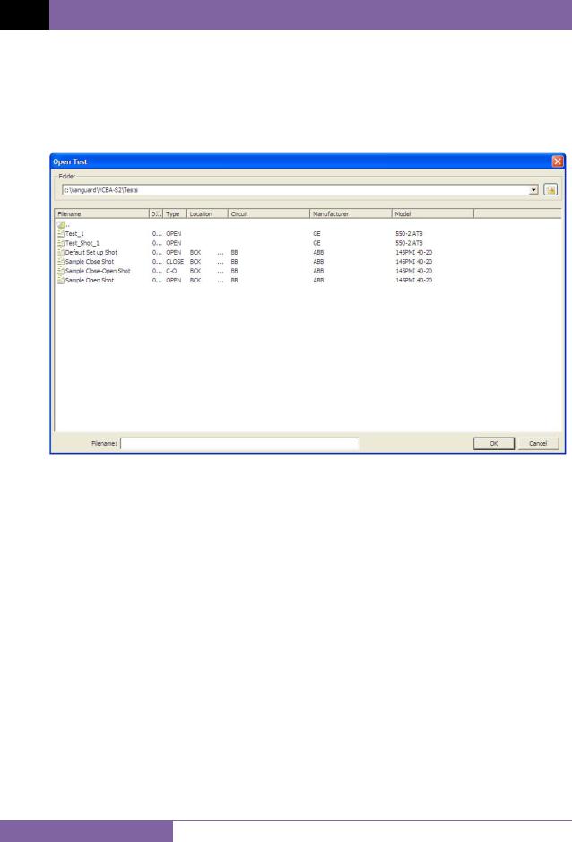
Use the steps below to open a test record from the PC hard drive:
1.Click on the Open icon in the Test command group in the Command Ribbon. The following screen will be displayed listing the test records from the default test record folder:
•The top left section of the window displays the name of the directory where the test records are being retrieved from. If you wish to retrieve records from a different directory, click on the folder icon at the top right of the window and browse to the folder containing your test records.
•You can sort the records by Filename, Date, Type of test, Location, Circuit, Manufacturer, or Model. To change the sort order, click on the header label that you would like to sort by. For example, if you would like the records to be sorted by Filename, click on the Filename column heading. You can reverse the sort order by clicking on the heading a second time.
14
VCBA S2 VERSION 4.xx SOFTWARE MANUAL REV 3
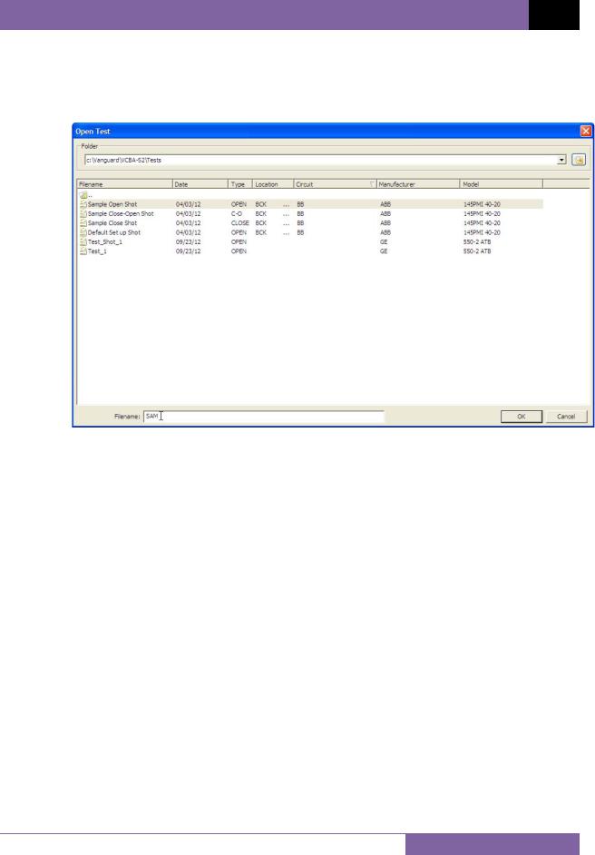
•You can also search for a particular filename. You can start typing in the “Filename” input field and it will actively highlight the first matching filename. For example, in the listing below, typing SAM in the “Filename” field will highlight the “Sample Open Shot” filename as shown below:
2.Click on the file name you would like to open and click the “OK” button. The test record will be loaded and the tabulated test results will be displayed (please see section 4.3 for details).
15
REV 3 VCBA S2 VERSION 4.xx SOFTWARE MANUAL
4.3Analyzing Test Records
Whenever a test record is loaded from the hard drive, the VCBA S2 software will automatically export the test record in the formats selected in the Application Settings preferences (please see section 3.2.3). For example, if you had configured the application to export reports in PDF format, the record will be exported as a PDF file when you load it from the hard drive. When loading a file from the hard drive, the following window will be displayed while the export function is being performed:
The exported PDF, Excel, and XML files are stored in subfolders named “Excel”, “Pdf”, and “Xml”, respectively, within the folder where the original test record is stored. For example, if the original test record is stored in the folder “C:\Vanguard\VCBA-S2\Tests”, the exported PDF file will be stored in the folder “C:\Vanguard\VCBA-S2\Tests\Pdf”.
16
VCBA S2 VERSION 4.xx SOFTWARE MANUAL REV 3
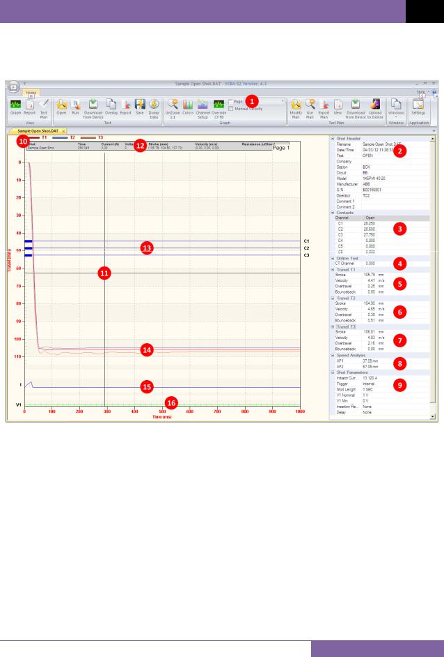
Once the test record is loaded and exported in the preferred formats, it will be displayed in graphical and tabulated format in the VCBA S2 application as shown in Figure 1 below. Please see Table 1 for a description of each numbered section.
Figure 1. Sample Test Record
17
REV 3 VCBA S2 VERSION 4.xx SOFTWARE MANUAL
Table 1. Description of Test Record Sections
Item |
Functional Description |
|
Number |
||
|
1Graph page number. Select which page to view from this drop-down menu.
2Test record header information. Test record header information can include identifying information such as the date and time the test was performed, the company name, model number, etc.
3Contact channel timing information.
4This section displays on-line timing information (if performed)
5Stroke, velocity, over-travel, and bounce-back values for contact channel 1
6Stroke, velocity, over-travel, and bounce-back values for contact channel 2
7Stroke, velocity, over-travel, and bounce-back values for contact channel 3
8Speed analysis information
9Additional test parameters such as initiator current, trigger type, shot length, etc.
10Travel Transducer Curve Color Legend
11Current cursor location
12Time, Current, Voltage, Stroke, Velocity, and Resistance values from current cursor location
13Graph for contact channels 1-3
14Travel curves for contacts 1-3
15Coil initiate current graph
16Voltage graph
Each section of the tabulated data can be collapsed or expanded. If a section is expanded, a “-” sign will be displayed to the left of it. Clicking on the “-” sign will collapse the section and hide its data. If a section is collapsed, a “+” sign will be displayed to the left of it. Clicking on the “+” sign will expand the section and display its data.
18

VCBA S2 VERSION 4.xx SOFTWARE MANUAL REV 3
4.4Viewing a Test Record’s Test Plan
You can view a test record’s test plan by clicking on the Test Plan icon in the View command group in the Command Ribbon. The test plan parameters will be displayed as shown in Figure 2 below.
Figure 2. Test Plan Parameters
You can return to the graph view by clicking on the Graph icon in the View command group in the Command Ribbon.
19
REV 3 VCBA S2 VERSION 4.xx SOFTWARE MANUAL
You may edit any of the test plan parameters by typing a new value in the corresponding input field. Once you have made your changes, be sure to click on the “Apply Changes” button (you may need to scroll down to see the button) to save your changes.
When a test record is saved, the test plan is saved along with it. You may also save the test plan as a separate test plan file. Please see section 5.1 for additional
NOTE information.
20
VCBA S2 VERSION 4.xx SOFTWARE MANUAL REV 3
4.5Customizing the Items Displayed on the Graph
You can select which contact, travel, and voltage traces are displayed on each page of the graphic test results. To select the items to be displayed:
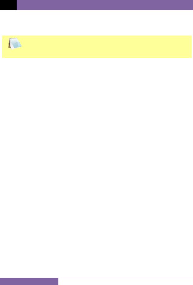
1.Click on the Channel Setup icon in the Graph command group in the Command Ribbon.
The following window will be displayed:
2.First, select the page number that you would like to customize by clicking on the corresponding radio box at the top of the window.
3.From each section, select the channels that you would like to display on the graph by selecting the channel number from the corresponding drop down menu. In the example above, contact channels 1, 2, and 3 will be displayed on the graph, voltage channel 1 will be displayed, current channel 1 will be displayed, and travel channels 1, 2, and 3 will be displayed.
4.Repeat the above process for additional pages, and then click on the “OK” button. The graph view will be updated to reflect any changes made.
|
The order of the contact and voltage channels can be arranged in any order by |
|
|
the user. This is determined by how they are selected from the dropdown |
|
NOTE |
menus. For example, if contact #3 is selected from the first dropdown menu, it |
|
will appear as the first item at the top of the graph. |
||
|
21
REV 3 VCBA S2 VERSION 4.xx SOFTWARE MANUAL
4.6 Customizing the Graph View
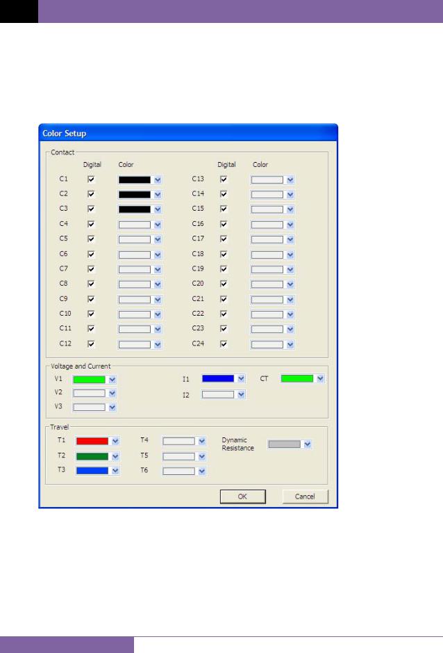
4.6.1. Customizing Graph Colors
Follow the steps below to customize the colors for each graph element:
1.Click on the Colors icon in the Graph command group in the Command Ribbon. The following window will be displayed:
To change the color for a particular graph element, click on the drop down menu next to the label for that item and select the preferred color.
Contact channel graphs can be displayed either as an analog graph or a digital graph (on/off). If you would like to view a contact channel’s graph as an analog graph, uncheck the “Digital” checkbox for that item. In the example shown in Figure 3, the contact channel 1 graph is shown in analog format while the contact channel 2 and 3 graphs are shown in digital format.
22
 Loading...