


Auto-Ohm 100-200 s2
OPERATING INSTRUCTIONS
for the
AUTO-OHM 100/200 Series 2
10-100/200 Amperes True DC
Digital Micro Ohm Meter
Vanguard Instruments Company, Inc.
TEL: (909) 923-9390 January 2009
FAX: (909) 923-9391 Rev. 3
1520 S. Hellman Ave.
Ontario, California 91761

AUTO-OHM 100/200 Series 2 Operating Procedures
SAFETY SUMMARY
NOTICE
This manual applies to Models Auto-Ohm 100 Series 2, and Auto-Ohm 200 Series 2. The
operating procedures are virtually the same for all models. Any differences are clearly
described in the step-by-step procedures.
FOLLOW EXACT OPERATING PROCEDURES
Any deviation from the procedures described in this operator’s manual may create one or more
safety hazards, damage the Auto-Ohm, or cause errors in the test results; Vanguard Instruments
Co., Inc. assumes no liability for unsafe or improper use of the Auto-Ohm.
The following safety precautions must be observed during all phases of test set-up, test hookups,
testing, and test-lead disconnects.
SAFETY WARNINGS AND CAUTIONS
This device shall be used only by trained operators.
All circuit breakers under test shall be off line and fully isolated.
DO NOT MODIFY TEST EQUIPMENT
Because of the risk of introducing unknown hazards, do not install substitute parts or perform
any unauthorized modification to any Model Auto-Ohm Test unit. To ensure that all designed
safety features are maintained, it is recommended that repairs be performed only by Vanguard
Instruments Co. factory personnel or by an authorized repair service. Unauthorized modifications
can cause serious safety hazards and will nullify the manufacturer's warranty.
2 Rev 3, 2009

AUTO-OHM 100/200 Series 2 Operating Procedures
Table of Contents
1.0 INTRODUCTION .............................................................................................................. 6
1.1 Applicability ......................................................................................................................... 6
1.2 General Description..............................................................................................................6
1.3 Functional Description.......................................................................................................... 6
1.4 Furnished Test Accessories................................................................................................... 6
1.5 Optional Accessories ............................................................................................................ 9
2.0 AUTO-OHM SPECIFICATIONS.................................................................................... 10
2.1 Auto-Ohm 100 Series 2 Specifications............................................................................... 10
2.2 Auto-Ohm 200 Series 2 Specifications............................................................................... 11
3.0 CONTROL AND DISPLAY............................................................................................12
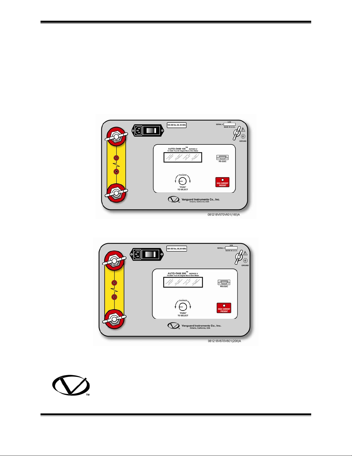
3.1 Auto-Ohm 100 Series 2 Front Panel................................................................................... 12
3.2 Auto-Ohm 200 Series 2 Front Panel................................................................................... 14
4.0 OPERATING VOLTAGES.............................................................................................. 16
5.0 CABLE CONNECTION .................................................................................................. 16
6.0 OPERATING THE AUTO-OHM .................................................................................... 19
6.1 Step-by-Step Procedures..................................................................................................... 19
6.2 Precautions.......................................................................................................................... 19
6.3 Preparations......................................................................................................................... 19
6.4 Running a Normal Test Procedure...................................................................................... 20
6.5 Running an Automatic Test Procedure............................................................................... 23
6.6 Auto-Ohm Quick Test Procedure ....................................................................................... 25
6.7 Contrast Adjustment ........................................................................................................... 25
6.8 Auto-Ohm Calibration Check............................................................................................. 26
6.9 Display Previous Results .................................................................................................... 29
List of Tables
Table 1.0 Auto-Ohm 100 Series 2 Specifications............................................................. 10
Table 2.0 Auto-Ohm 200 Series 2 Specifications............................................................. 11
Table 3.0 Functional Description of Auto-Ohm 100 Series 2 Controls and Display ....... 13
Table 4.0 Functional Description of Auto-Ohm 200 Series 2 Controls and Display ....... 15
3 Rev 3, 2009

AUTO-OHM 100/200 Series 2 Operating Procedures
Table of Figures
Figure 1.0 Combined Current and Sense Leads....................................................................... 7
Figure 2.0 Auto-Ohm 100/200 Sense Leads............................................................................7
Figure 3.0 Auto-Ohm 100/200 Hand Spikes............................................................................ 8
Figure 4.0 Auto-Ohm 100/200 Current Cable.......................................................................... 8
Figure 5.0 Auto-Ohm 100/200 C-Clamp Cable....................................................................... 9
Figure 6.0 Auto-Ohm 100 Series 2 Control-Panel Controls and Display.............................. 12
Figure 7.0 Auto-Ohm 200 Series 2 Control-Panel Controls and Display.............................. 14
Figure 8.0 AUTO-OHM 100/200 Connection Diagram 1 (Separate Leads)......................... 16
Figure 9.0 AUTO-OHM 100/200 Connection Diagram 2 (Combined Leads) ...................... 16
Figure 10.0 AUTO-OHM 100/200 Connection Diagram 3 (Separate Leads)......................... 17
Figure 11.0 AUTO-OHM 100/200 Connection Diagram 4 (Combined Leads)...................... 17
Figure 12.0 Step-by-Step Procedures for Auto-Ohm Operation.............................................. 18
Figure 13.0 Main Menu............................................................................................................ 19
Figure 14.0 Test Type Menu <NORMAL> ............................................................................. 20
Figure 15.0 Select 10A Menu................................................................................................... 20
Figure 16.0 Select Custom Current Menu................................................................................ 20
Figure 17.0 Custom Current Menu........................................................................................... 20
Figure 18.0 The BURN-IN TIME Menu.................................................................................. 21
Figure 19.0 The RAMP TIME Menu....................................................................................... 21
Figure 20.0 Test Current & Burn-In Time............................................................................... 21
Figure 21.0 Current Ramp Message......................................................................................... 21
Figure 22.0 The BURNING IN Menu...................................................................................... 22
Figure 23.0 Test Current & Resistance Readings .................................................................... 22
Figure 24.0 The REPEAT TEST Menu ................................................................................... 22
Figure 25.0 Cable Error Message............................................................................................. 22
Figure 26.0 Test Type Menu <AUTOMATIC>....................................................................... 23
Figure 27.0 Select 10A Menu................................................................................................... 23
Figure 28.0 Select Custom Current Menu................................................................................ 23
Figure 29.0 Custom Current Menu........................................................................................... 24
Figure 30.0 The Ramp Time Menu.......................................................................................... 24
Figure 31.0 Select 50 Amperes Menu...................................................................................... 24
Figure 32.0 Auto Test Mode Menu.......................................................................................... 24
Figure 33.0 Automatic Mode Test results................................................................................ 25
Figure 34.0 Quick Test Menu................................................................................................... 25
Figure 35.0 Select Adjust Contrast Menu................................................................................ 25
Figure 36.0 Contrast Menu....................................................................................................... 25
Figure 37.0 100A Cal Check.................................................................................................... 26
Figure 38.0 Attach Short Bar Prompt....................................................................................... 26
Figure 39.0 Calibration Connection (Separate Leads)............................................................. 26
Figure 40.0 Calibration Connection (Combined Leads).......................................................... 27
Figure 41.0 Current Ramp Message......................................................................................... 27
Figure 42.0 Current-Ramp Error Message............................................................................... 27
Figure 43.0 Current Ramp Circuit Pass Message..................................................................... 27
Figure 44.0 Zero Circuit Test Message.................................................................................... 28
Figure 45.0 Full-Scale Circuit Test Message........................................................................... 28
Figure 46.0 Measure Circuit Test Message.............................................................................. 28
4 Rev 3, 2009

AUTO-OHM 100/200 Series 2 Operating Procedures
Figure 47.0 Cal Check Complete Message.............................................................................. 28
Figure 48.0 Previous Results Menu ......................................................................................... 29
Figure 49.0 Select Reading Menus........................................................................................... 29
Figure 50.0 Test Record Readout............................................................................................. 29
5 Rev 3, 2009

AUTO-OHM 100/200 Series 2 Operating Procedures
1.0 INTRODUCTION
1.1 Applicability
This manual applies to the Model Auto-Ohm 100 Series 2 and Model Auto-Ohm 200 Series 2
(hereafter, Auto-Ohm), made by Vanguard Instruments Company.
1.2 General Description
The Auto-Ohm-100/200 Series 2 are the third generation micro-ohmmeters made by Vanguard
Instruments Company. The Auto-Ohm 100/200 features microprocessor-controlled measuring of
very low resistances ranging from 1 micro-ohm to 300 milli-ohms with high accuracy. The AutoOhm is field-portable, rugged, and easily operated by first-time users having a minimum of
training. It features one-knob control and an LCD alpha/numeric display of the resistance
measured. The one-knob control operation is logical and simple: Turning the knob scrolls
through a menu of possible options (which display in sequence) and pressing the knob activates
the selected function. As its name implies, the Auto-Ohm operation is automatic, requiring little
more from the user than connecting it to an unknown resistance and selecting the desired
functions and its options. The Auto-Ohm automatically stores the last 3 resistance measurements,
which can be displayed after testing.
1.3 Functional Description
The Auto-Ohm’s operation is based on the electrical relationships described by Ohm’s law:
R=V/I, where I is a known current and V is the dc voltage measured across the unknown
resistance (typically, a circuit breaker’s contacts). Since the current (user selected) through the
unknown resistance is known and the voltage across the unknown resistance is measured by a
precision voltmeter, the resistance read-out can be calculated using Ohm’s law.
The Auto-Ohm test voltage is supplied by a true 5Vdc power supply. The true DC test current is
selectable in 2-amp steps, from 10 to 100 amperes for the Auto-Ohm-100 and from 10 to 200
amperes for Auto-Ohm-200. The test current is automatically ramped up and down slowly. This
current ramp rate is programmable from 5 seconds to 30 seconds.
The voltmeter test leads run separately from the current-bearing test leads to the resistive load
thus eliminating any I•R voltage drop error in the current cables. These Auto-Ohm features make
very precise micro-ohm measurements possible without having to calculate compensations for
current lead resistance errors.
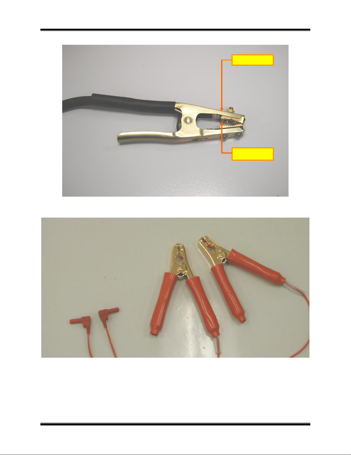
1.4 Furnished Test Accessories
The Auto-Ohm is supplied with two 30-foot test cables with heavy-duty alligator clamps. Both
the current (#1 AWG) and sense leads are combined into one cable (Figure 1.0). A Ground cable,
and power cord are also included with each Auto-Ohm.
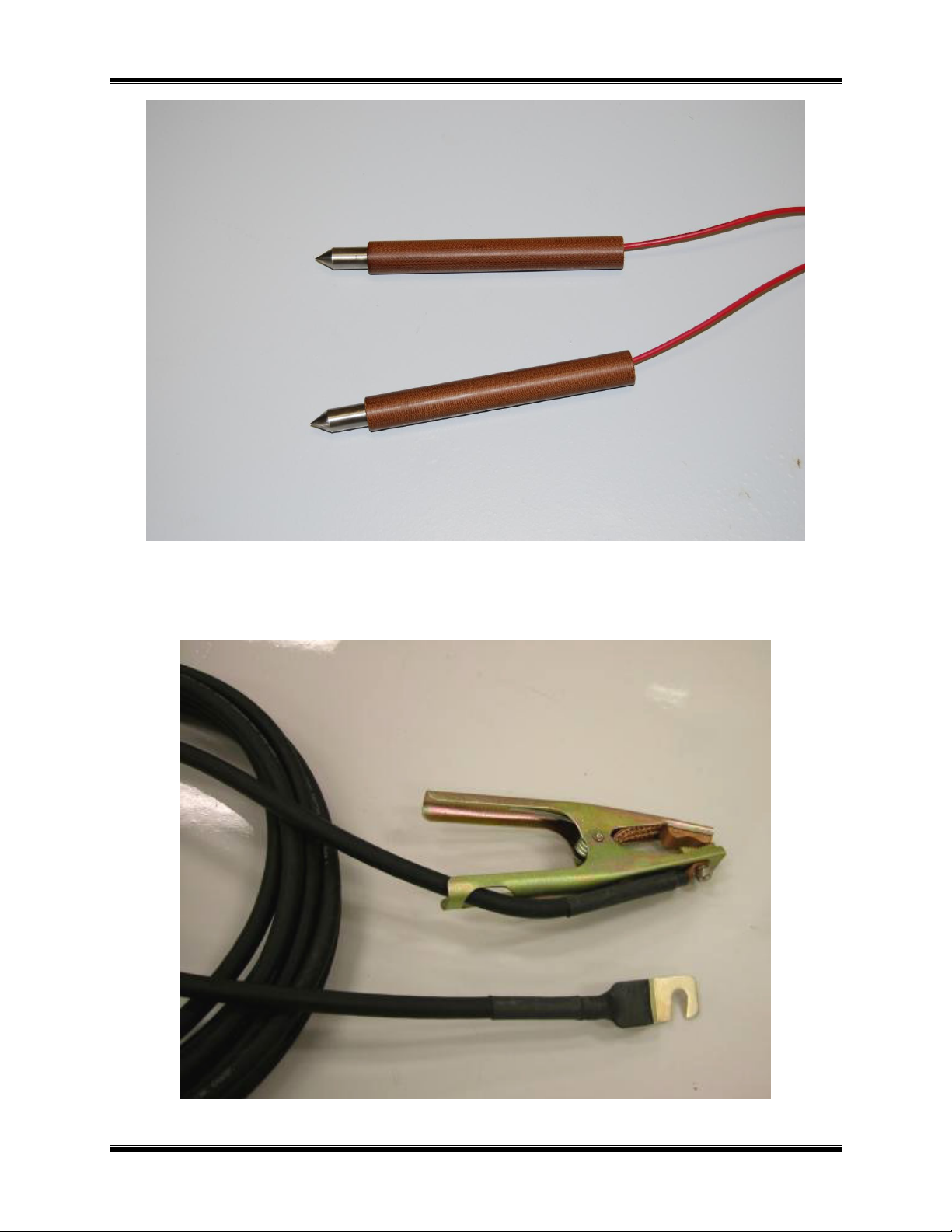
Users can select to have the current and sense leads separated as shown in Figure 2.0 and Figure
4.0. Optional hand spike sense leads are also available as shown in Figure 3.0.
6 Rev 3, 2009
AUTO-OHM 100/200 Series 2 Operating Procedures
Current Jaw
Voltage Jaw
Figure 1.0 Combined Current and Sense Leads
Figure 2.0 Auto-Ohm 100/200 Sense Leads
7 Rev 3, 2009
AUTO-OHM 100/200 Series 2 Operating Procedures
Figure 3.0 Auto-Ohm 100/200 Hand Spikes
Figure 4.0 Auto-Ohm 100/200 Current Cable
8 Rev 3, 2009
AUTO-OHM 100/200 Series 2 Operating Procedures
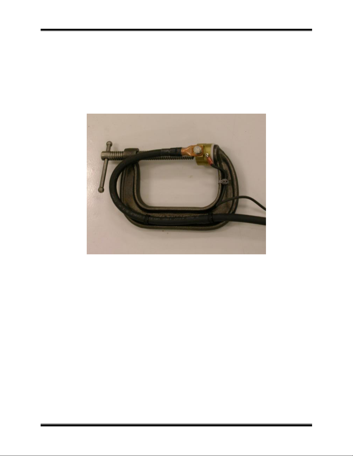
1.5 Optional Accessories
1. Heavy-duty welding-type C-clamps (Figure 5.0) are available as optional accessories.
These C-clamps allow test lead connections to a wide variety of bushing sizes, bus bars,
and conductors that require low-resistance test-lead contacts.
2. Light weight (#4 AWG) cables are also available upon request.
3. Custom cable lengths are available upon request.
4. An optional shipping case (which holds the Auto-Ohm and its cables) is also available.
Figure 5.0 Auto-Ohm 100/200 C-Clamp Cable
9 Rev 3, 2009

AUTO-OHM 100/200 Series 2 Operating Procedures
2.0 AUTO-OHM SPECIFICATIONS
2.1 Auto-Ohm 100 Series 2 Specifications
Table 1.0 Auto-Ohm 100 Series 2 Specifications
MODEL...................... Auto-Ohm 100 Series 2
TYPE............................. Special-Purpose Test Equipment, Portable, Low Resistance-Ohmmeter
CONFIGURATION...... Third-generation (improved design, superseding original model)
SIZE (inches).............. 16.8 Wide by 12.6 High by 10.6 Deep (42.7 Cm x 32 Cm x 30.5 Cm)
WEIGHT........................ Less than 15 pounds (6.8 Kg)
OPERATING
VOLTAGE.................... 8 amps, 100-240 Vac, 50/60 Hz, with built in 10A circuit breaker
RESISTANCE
RANGE......................... 1 micro-ohm to 300 milli-ohms
TEST CURRENT
RANGE......................... 10 Amperes to 100 Amperes, Selectable in 2 ampere steps
DISPLAY...................... Backlit LCD, 2-lines high by 16 characters Wide
ACCURACY................. ± 1 % of Reading, ± 1 Count
UNIT PROTECTION... thermal-overload sensor and cutoff
INTERFACE................. RS-232C Connector Port for PC Interface
ENVIRONMENT.......... Operating: 0°C to 55°C; Storage: -40°C to 65°C
FURNISHED ITEMS... One power cord, one ground cable, two 30-ft. test lead cables.
WARRANTY................ One-Year Parts & Labor (Post-Warranty Service Contracts Available)
AUTO-OHM SPECIFICATIONS ARE SUBJECT TO UPGRADES AND MAY BE CHANGED WITHOUT PRIOR NOTICE.
10 Rev 3, 2009
 Loading...