


TRM-203 and TRM-403
TRANSFORMER RESISTANCE METERS
USER’S MANUAL
Vanguard Instruments Company, Inc.
1520 S. Hellman Ave.
Ontario, California 91761, USA
TEL: (909) 923-9390 |
November 2013 |
FAX: (909) 923-9391 |
Revision 1.3 |
|
|

TRM-203 AND TRM-403 USER’S MANUAL REV 1
SAFETY SUMMARY
NOTICE
This manual applies to both the TRM-203 and TRM-403 transformer resistance meters. The operating procedures are virtually the same for both models, and any differences are clearly described where applicable.
FOLLOW EXACT OPERATING PROCEDURES
Any deviation from the procedures described in this User’s Manual may create one or more safety hazards, may damage the TRM-203/403, damage the test transformer, or cause errors in the test results. Vanguard Instruments Company, Inc. assumes no liability for unsafe or improper use of the TRM-203/403.
All safety precautions provided in this manual must be observed during all phases of testing including test preparation, test lead connection, actual testing, and test lead disconnection.
SAFETY WARNING AND CAUTIONS
The TRM-203/403 shall be used only by trained operators. All transformers under test shall be off-line and fully isolated.
DO NOT MODIFY TEST EQUIPMENT
To avoid the risk of introducing additional or unknown hazards, do not install substitute parts or perform any unauthorized modification to any TRM-203/403 test unit. To ensure that all designed safety features are maintained, it is highly recommended that repairs be performed only by Vanguard Instruments Company factory personnel or by an authorized repair service provider. Unauthorized modifications can cause safety hazards and will void the manufacturer’s warranty.
WARNING
Do not remove test leads during a test. Failure to heed this warning can result in electrical shock to personnel and damage to the equipment.
 i
i

REV 1 TRM-203 AND TRM-403 USER’S MANUAL
TABLE OF CONTENTS
CONVENTIONS USED IN THIS DOCUMENT ..................................................................................... |
1 |
|||
1.0 |
INTRODUCTION.................................................................................................................... |
2 |
||
1.1 |
|
General Description and Features ................................................................................... |
2 |
|
1.2 |
|
Technical Specifications ................................................................................................... |
4 |
|
1.3 |
|
TRM Controls and Indicators ........................................................................................... |
5 |
|
2.0 |
PRE-TEST SETUP ................................................................................................................... |
6 |
||
2.1 |
|
Operating Voltages .......................................................................................................... |
6 |
|
2.2 |
|
LCD Screen Contrast Control............................................................................................ |
6 |
|
2.3 |
|
Printer Paper Control....................................................................................................... |
6 |
|
2.4 |
|
Printer Paper.................................................................................................................... |
6 |
|
2.5 |
|
Replacing the Thermal Printer Paper............................................................................... |
7 |
|
3.0 |
OPERATING PROCEDURES ................................................................................................... |
8 |
||
3.1 |
|
Configuring the LTCA Software for use with the TRM..................................................... |
8 |
|
3.2 |
|
Connecting the TRM to a PC via Bluetooth ................................................................... |
10 |
|
3.3 |
|
Typical Connections to a Load Tap Changer (LTC)......................................................... |
17 |
|
3.4 |
|
Typical TRM-203/403 Cable Connections...................................................................... |
17 |
|
3.5 |
|
General Procedures ....................................................................................................... |
17 |
|
3.6 |
|
Entering Test Record Header Information..................................................................... |
19 |
|
3.7 |
|
Setting the Date and Time ............................................................................................. |
23 |
|
3.8 |
|
Setting the Interface Language...................................................................................... |
24 |
|
3.9 |
|
Performing a Three-Phase Resistance Test ................................................................... |
25 |
|
3.10 |
Performing a Single-Phase Resistance Test ................................................................... |
35 |
||
3.11 |
Performing a Load Tap Changer / Voltage Regulator Resistance Test .......................... |
42 |
||
3.12 |
Performing a Special Resistance Test ............................................................................ |
51 |
||
3.13 |
Performing a Dynamic LTC Test ..................................................................................... |
58 |
||
3.14 |
Performing a Diagnostic Test......................................................................................... |
63 |
||
3.15 |
Demagnetizing the Transformer Core ........................................................................... |
65 |
||
3.16 |
Working with Test Records............................................................................................ |
67 |
||
3.16.1. |
Saving Test Records................................................................................................ |
67 |
||
3.16.2. Printing the Contents of the Working Memory ..................................................... |
69 |
|||
3.16.3. Printing a Test Record Directory ............................................................................ |
70 |
|||
3.16.4. Restoring a Test Record.......................................................................................... |
73 |
|||
3.16.5. Copying Test Records to a USB Flash Drive............................................................ |
77 |
|||
3.16.6. |
Erasing Test Records............................................................................................... |
80 |
||
3.17 |
Converting Resistance Measurements .......................................................................... |
85 |
||
ii

|
TRM-203 AND TRM-403 USER’S MANUAL |
REV 1 |
|
LIST OF FIGURES |
|
Figure 1. TRM-203/403 Controls and Indicators ............................................................................ |
5 |
|
Figure 2. Typical Connections to a Load Tap Changer (LTC)......................................................... |
17 |
|
Figure 3. Typical TRM Connections Diagram ................................................................................ |
17 |
|
Figure 4. Typical Three-Phase (Delta) Resistance Test Results Printout ...................................... |
33 |
|
Figure 5. Typical Three-Phase (Wye with Neutral) Resistance Test Results Printout .................. |
34 |
|
Figure 6. |
Typical Single Phase Resistance Test Results Printout .................................................. |
41 |
Figure 7. |
Typical LTC/Voltage Regulator Test Report Printout..................................................... |
50 |
Figure 8. |
Typical Special Resistance Test Results Printout ........................................................... |
57 |
Figure 9. |
Typical Dynamic LTC Test Results Printout Showing an Opened Circuit ....................... |
62 |
Figure 10. Sample Thumb Drive Test Record Directory Printout ................................................. |
72 |
|
Figure 11. Sample Internal Test Record Directory Printout ......................................................... |
72 |
|
LIST OF TABLES
Table 1. TRM-203/403 Technical Specifications............................................................................. |
4 |
iii
REV 1 TRM-203 AND TRM-403 USER’S MANUAL
CONVENTIONS USED IN THIS DOCUMENT
This document uses the following conventions:
•Both the TRM-203 and TRM-403 are simply referred to as “TRM” in this manual. The exact model number is used only in cases where differences between the units are discussed.
•A key, switch, or knob on the TRM is indicated as [KEY], [SWITCH], [KNOB].
•Menu names are referenced as “MENU NAME”
•TRM LCD screen output is shown as:
1.OPTION 1
2.OPTION 2
3.OPTION 3
4.OPTION 4
5.OPTION 5
•When instructions are provided, the menu item that should be selected is printed in bold as shown below (option 3 should be selected in this example):
1.OPTION 1
2.OPTION 2
3.OPTION 3
4.OPTION 4
5.OPTION 5
•Warning messages are indicated as:
Warning message
WARNING
•Important notes are indicated as:
Note details
NOTE
1

TRM-203 AND TRM-403 USER’S MANUAL REV 1
1.0INTRODUCTION
1.1General Description and Features
The TRM-203 and TRM-403 are three phase transformer winding resistance meters that allow the user to connect all test cables to the transformer bushings. The unit will then measure the transformer resistance value for each of the phases without the need to disconnect and reconnect cables for each phase.
The TRM-203 and TRM-403 can provide a fast and stable reading of very large transformers by utilizing a 60Vdc power supply. The TRM-203 is capable of outputting a selectable test current from 1A to 20A while the TRM-403’s test current is selectable from 1A to 40A.
Since both units can accurately measure resistance from 1 micro-ohm to 500 Ohms (up to 2000 Ohms for the TRM-203), they can be used as micro-ohm meters to measure EHV circuit breaker contact resistance, or for any low resistance measuring application.
For a Delta transformer, the TRM-203/403 can measure the phase resistance readings and provide the individual Delta winding resistance values. The TRM-203/403 can also provide the individual winding resistance values for a Wye transformer without the neutral terminal.
If the transformer winding resistance temperature is available at the time of testing, the TRM203/403 can calculate the equivalent resistance value at any temperature value. This useful feature can be used to compare the field readings against the factory test resistance values.
The TRM-203/403 can perform a special test to collect data automatically for up to 90 minutes (at 60-second sampling intervals) or 45 minutes (at 30 second sampling intervals). The test data is recorded with a time stamp.
All test results can be printed on the unit’s built-in 2.5” wide thermal printer. Test record header information including the company, substation name, transformer information, and operator information can also be entered using the rugged, 44–key “QWERTY”-style membrane keypad.
The TRM-203/403 can automatically demagnetize the inductive device under test, eliminating the manual task of demagnetizing the transformer core after a resistance test.
The TRM-203/403 also has a “make-before-break” test mode that can be used to test the Load Tap Changer (LTC) or Voltage Regulator contact test sequence. The TRM-203/403 produces a “Dynamic-Resistance” graph of the LTC or Voltage regulator contact under operation. An opened contact can be detected visually from this resistance chart.
The TRM’s built-in LTC/Voltage regulator can be used to conveniently change the LTC/voltage regulator tap position from the TRM-203/403 front panel.
User Interface
The TRM-203/403 features a back-lit graphic LCD screen (128 x 64 pixels) that is clearly visible in both bright sunlight and low light levels. A 44-key “QWERTY”-style membrane keypad is used to enter test information and operate the unit.
2

REV 1 TRM-203 AND TRM-403 USER’S MANUAL
Computer Interface
The TRM-203/403 can be connected to a PC via the unit’s RS-232C, USB, or Bluetooth interface. A PC can be used to control the TRM-203/403 to perform transformer resistance tests. Test records (stored in the TRM-203/403 or a USB Flash drive) can also be retrieved, reviewed, and printed. Test records are automatically exported to PDF, Excel, and XML formats.
Safety Features
The TRM-203/403 automatically dissipates the energy stored in the transformer at the end of each test. The discharge circuit will continue to work even if the TRM-203/403 power supply is lost.
Test Record Storage
The TRM-203/403 can store up to 256 static test records (111 tests per record) and 120 dynamic test records internally. For external test record storage, the TRM-203/403 features a USB Flash drive interface port. Up to 999 test records can be stored on a connected USB Flash Drive.
3

TRM-203 AND TRM-403 USER’S MANUAL REV 1
1.2Technical Specifications
Table 1. TRM-203/403 Technical Specifications
TYPE |
Portable transformer winding resistance meter |
PHYSICAL SPECIFICATIONS |
21” W x 17” H x 9” D (53 cm x 43 cm x 24 cm); Weight: 35 lbs (15.8Kg) |
OPERATING VOLTAGE |
100-240 Vac, 50/60 Hz |
RESISTANCE READING |
1 micro-ohm – 2000 Ohms (TRM-203); |
RANGE |
1 micro-ohm – 500 Ohms (TRM-403) |
ACCURACY |
1 – 19,999 micro-ohms: ±0.5% reading, ±1 count; |
|
20 – 999 milliohms: ±1% reading, ±1 count; |
|
1 -2000 Ohms: ±1.5% reading, ±1 count |
TEST CURRENT |
1-20A in 1A increments (TRM-203); 1-40A in 1A increments (TRM403) |
TEST VOLTAGE |
60Vdc charging, 18V DC max during measurement |
INPUT CHANNELS |
4 input channels for measuring resistance |
DISPLAY |
Back-lit LCD Screen (128 x 64 pixels), viewable in direct sunlight and low |
|
light levels |
PRINTER |
Built-in 2.5” wide thermal printer |
|
|
INTERNAL DATA STORAGE |
256 static test records (each can contain up to 111 readings) and 120 |
|
dynamic test records |
EXTERNAL DATA STORAGE |
Up to 999 test records on external USB Flash drive |
COMPUTER INTERFACES |
RS-232C, USB, and Bluetooth |
SAFETY |
Designed to meet UL 61010A-1 and Can/CSA C22.2 No 1010.1092 |
|
standards |
ENVIRONMENT |
Operating: -10˚C to 50˚ C (15˚F to +122˚ F); Storage: -30˚ C to 70˚ C (- |
|
22˚F to +158˚ F) |
HUMIDITY (MAX) |
90% RH @ 40° C (104° F) non-condensing |
ALTITUDE (MAX) |
2000m (6562 ft) to full safety specifications |
CABLES |
Four 50-foot test cables, one LTC control cable, one ground cable, one |
|
power cord, one USB cable |
OPTIONS |
Transportation Case |
WARRANTY |
One year on parts and labor |
The above specifications are valid at nominal operating voltage and at a temperature of 25°C (77°F). Specifications may change without prior notice.
NOTE
4
REV 1 TRM-203 AND TRM-403 USER’S MANUAL
1.3TRM Controls and Indicators
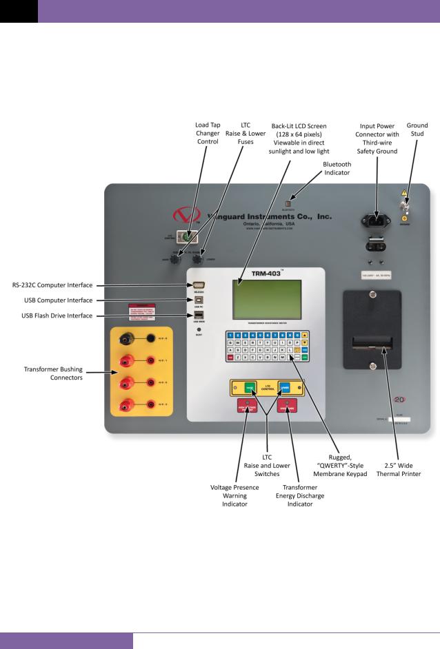
The TRM-203/403’s controls and indicators are shown in Figure 1. The purpose of the controls and indicators may seem obvious, but users should become familiar with them before using the TRM. Accidental misuse of the controls will usually cause no serious harm. Users should also be familiar with the safety summary found on the front page of this User’s Manual.
Figure 1. TRM-203/403 Controls and Indicators
5

TRM-203 AND TRM-403 USER’S MANUAL REV 1
2.0PRE-TEST SETUP
2.1Operating Voltages
The TRM’s operating voltages are 100-240 Vac, 50/60 Hz.
2.2LCD Screen Contrast Control
To increase the LCD screen contrast, press and hold the [ ] key for at least two seconds. Release the [ ] key when the desired contrast level has been reached.
To decrease the LCD screen contrast, press and hold the [ ] key for at least two seconds. Release the [ ] key when the desired contrast level has been reached.
2.3Printer Paper Control
To advance the TRM printer paper, press and release the [ ] key.
To retract the TRM printer paper, press and release the [ ] key.
2.4Printer Paper
The TRM’s built-in thermal printer uses 2.5-inch wide thermal paper for printing test results. To maintain the highest print quality and to avoid paper jams, the use of thermal paper supplied by Vanguard Instruments Company is highly recommended. Additional paper can be ordered from the following sources:
Vanguard Instruments Co, Inc.
1520 S. Hellman Avenue Ontario, CA 91761
Tel: 909-923-9390
Fax: 909-923-9391
Part Number: VIC TP-3 paper
BG Instrument Co.
13607 E. Trent Avenue Spokane, WA 99216 Tel: 509-893-9881 Fax: 509-893-9803
Part Number: VIC TP-3 paper
6
REV 1 TRM-203 AND TRM-403 USER’S MANUAL
2.5Replacing the Thermal Printer Paper
The roll of thermal paper is housed inside a dispenser underneath the printer cover. To replace the paper, follow the steps below:
•Unscrew the two large printer cover screws and remove the printer cover.
•Remove the leftover thermal paper roll from the paper holder.
•Unroll the new thermal paper roll.
•Feed the thermal paper into the slot between the paper pocket and the rubber roller. The printer will automatically pull the paper under the thermal head.
•Place the paper roll into the paper holder.
•Lift the thermal head and align the thermal paper if necessary.
•Re-install the printer cover.
Thermal paper has a chemical coating on one side of the paper. This side should be facing the thermal print head. Incorrect paper loading may result in blank output on
the thermal paper.
NOTE
The thermal paper will show a red stripe to indicate that the roll is about to run out of paper.
7
TRM-203 AND TRM-403 USER’S MANUAL REV 1
3.0OPERATING PROCEDURES
3.1Configuring the LTCA Software for use with the TRM
The TRM can be used with a PC using the Vanguard LTCA software. Follow the steps below to properly connect the TRM and configure the LTCA application to recognize the unit.
a.Install the LTCA software (please see the LTCA software user’s manual for details).
b.Connect the TRM to the PC by connecting a USB cable from an open USB port on the PC to the unit’s “USB PC” port.
c.Turn on the power on the TRM.
d.If this is the first time you are connecting the unit to the PC, Windows will recognize it as a new device and automatically install necessary drivers. If using Windows XP, you may be prompted to install drivers. Select the automatic installation option and Windows will locate the generic drivers necessary.
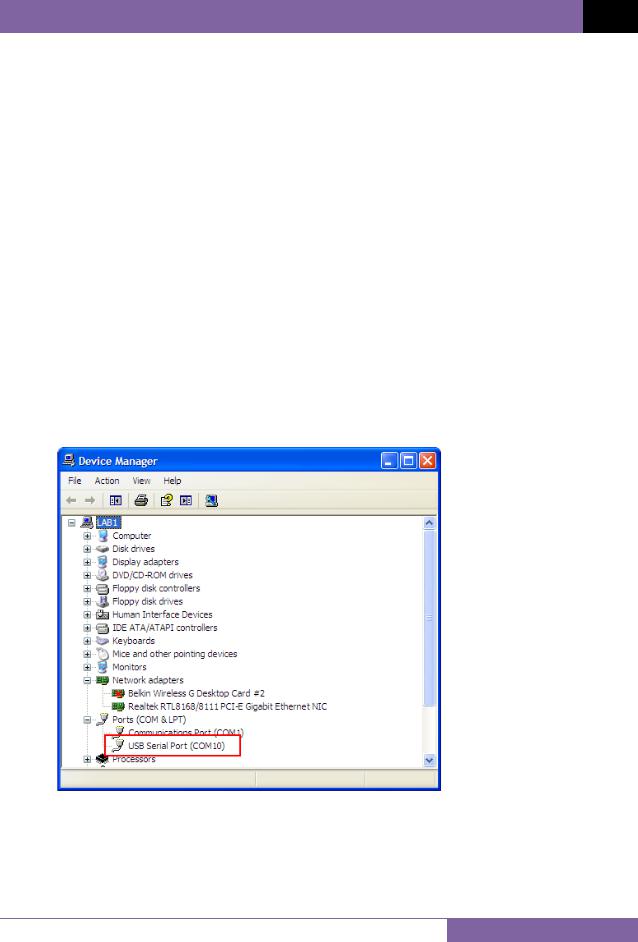
e.Please note that although the unit is connected via USB, it uses an internal serial interface to communicate with the PC. As such, it will appear in the windows Device Manager as a USB Serial Port. Open the Device Manager from the Windows Control Panel and note the COM port number. For example, in the installation shown below, the TRM is shown as COM10 (USB Serial Port).
8
REV 1 TRM-203 AND TRM-403 USER’S MANUAL
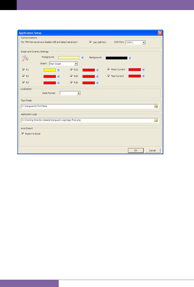
f.Launch the LTCA application and then click on the “Settings” icon. The following window will be displayed:
Make sure the “User USB Port” is UN-checked. Then, from the “COM Port” drop-down menu, select the COM port that corresponds to the port that the TRM is connected to. Then click the OK button. The LTCA software will now recognize the TRM.
9
TRM-203 AND TRM-403 USER’S MANUAL REV 1
3.2Connecting the TRM to a PC via Bluetooth
The TRM can also be connected wirelessly to a PC using Bluetooth. To connect the unit via Bluetooth, it must first be paired with the PC. Follow the steps below to pair the TRM to a PC via Bluetooth:
For Windows XP:
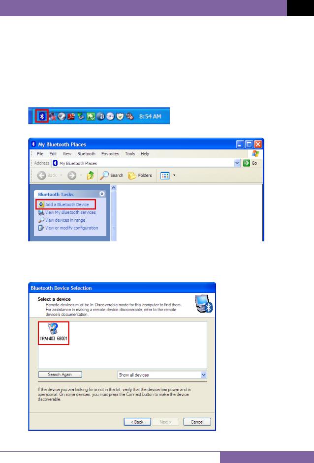
a.Make sure the TRM is turned on. Then double click on the Bluetooth system tray icon (on the bottom right corner of your computer screen):
b.The “My Bluetooth Places” window will be displayed:
Click on “Add a Bluetooth Device” on the left window pane.
c.The Bluetooth Setup Wizard window will be displayed. Click on the “Next” button. The PC will scan for nearby devices and list all available Bluetooth devices:
10
REV 1 TRM-203 AND TRM-403 USER’S MANUAL
The TRM will be listed as “TRM S/N” where S/N is the device’s serial number. Click on the icon for the TRM and then click on the “Next” button.
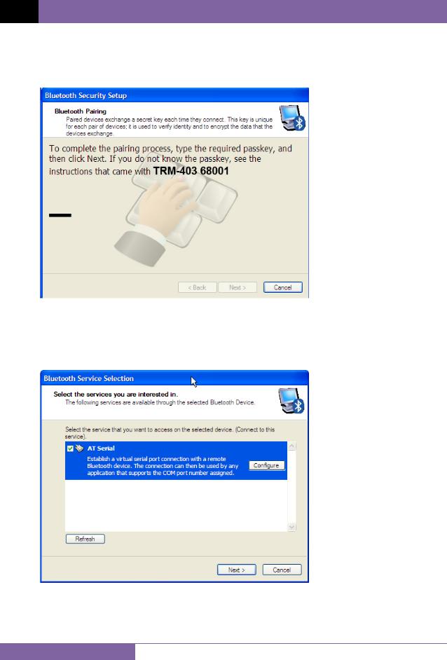
d. The following window will be displayed asking for a secret key to connect to the TRM:
Type the word “default” (without the quotes and in all lower-case) and then click on the “Next” button.
e.The following window will be displayed with the option to connect to the TRM as a serial port:
Make sure to check the box next to “AT Serial” and then click on the “Next” button.
11

TRM-203 AND TRM-403 USER’S MANUAL REV 1
f. The following confirmation screen will be displayed:
Click on the “Finish” button.
g. The TRM-20 will now be displayed in the “My Bluetooth Places” window:
Note the port number listed under the device name. In the above case, the port number is COM14. Use this port number in the LTCA software to connect to the TRM.
12
REV 1 TRM-203 AND TRM-403 USER’S MANUAL
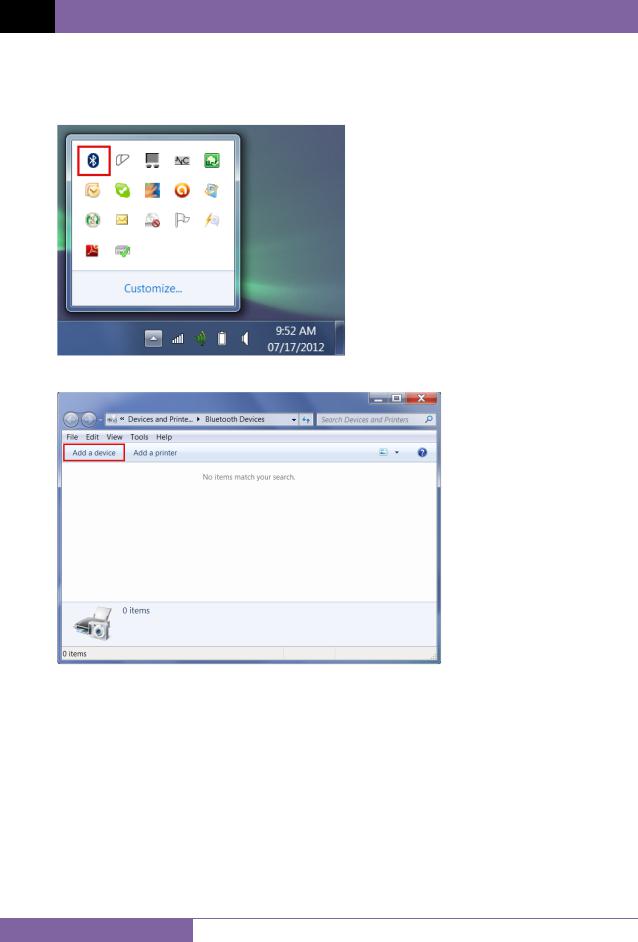
For Windows 7:
a.Make sure the TRM is turned on. Then double click on the Bluetooth system tray icon (on the bottom right corner of your computer screen):
b. The “Bluetooth Devices” window will be displayed:
Click on “Add a device”.
13

TRM-203 AND TRM-403 USER’S MANUAL REV 1
c. All nearby Bluetooth devices will be listed:
The TRM will be listed as “TRM S/N” where S/N is the device’s serial number. Click on the icon for the TRM and then click on the “Next” button.
d. The device pairing screen will be displayed:
Click on “Enter the device’s pairing code” option.
14
REV 1 TRM-203 AND TRM-403 USER’S MANUAL
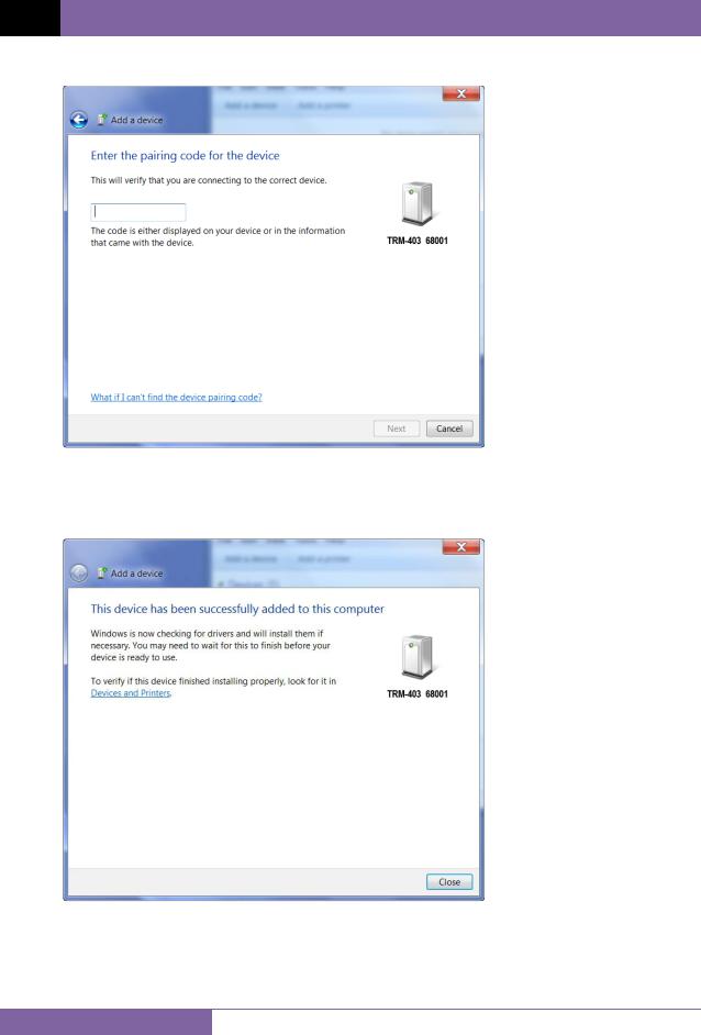
e. The following window will be displayed:
Type the word “default” (without the quotes and in all lower-case) in the text box and click on the “Next” button.
f. The following screen will be displayed:
Click on the “Close” button.
15
TRM-203 AND TRM-403 USER’S MANUAL REV 1
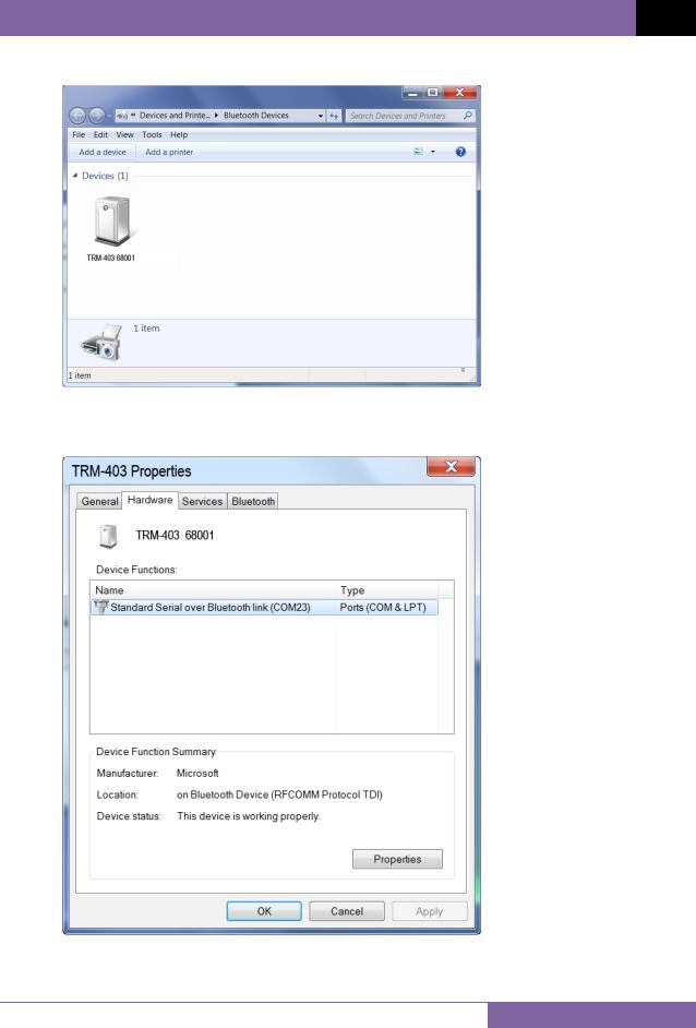
g. The TRM will now be listed under “Bluetooth Devices”:
Right click on the TRM-20 icon and select “Properties” from the pop-up menu.
h. The properties window will be displayed. Click on the “Hardware” tab:
Note the port number listed after the device name (COM23 in the above example). Use this port number in the LTCA software to connect to the TRM.
16

REV 1 TRM-203 AND TRM-403 USER’S MANUAL
3.3Typical Connections to a Load Tap Changer (LTC)
Figure 2. Typical Connections to a Load Tap Changer (LTC)
3.4Typical TRM-203/403 Cable Connections
•Do not touch or disconnect any test lead that is connected to a transformer terminal while high current is being conducted during a test. Failure to heed
WARNINGS |
this warning can result in electric shock to personnel and/or damage to the |
|
equipment. |
•Disconnect the test clips from the transformer bushing only after the TRM has completely discharged the transformer. Always disconnect the test clips slowly from the transformer bushing to prevent an accidental flash-over.
Figure 3. Typical TRM Connections Diagram
3.5General Procedures
17

TRM-203 AND TRM-403 USER’S MANUAL REV 1
The main steps for using the TRM are outlined below:
a. Ground the TRM to the substation ground.
Always connect the TRM to the substation ground before connecting any test lead to any transformer bushing. Failure to follow this procedure may
WARNING damage the TRM.
b.Plug the TRM power cable into a power outlet.
c.Attach the test cable clamps to the transformer terminals.
d.Turn on the TRM.
e.The unit will self-calibrate, and then you will be presented with the “START-UP” menu as shown below:
1. RUN TEST |
07/25/12 |
|
11:06:21 |
||
2. SETUP |
||
23°C 73°F |
||
|
||
3. USER DIAGNOSTICS |
||
|
|
|
18

REV 1 TRM-203 AND TRM-403 USER’S MANUAL
3.6Entering Test Record Header Information
You can enter the test record header information before performing tests. The record header includes identifying information such as the company, station, circuit, model number, etc. Once the header information has been entered, it will apply to all subsequent test records. To enter the header information:
a. Start from the “START-UP” menu:
1. RUN TEST |
07/25/12 |
|
11:45:35 |
||
2. SETUP |
||
22°C 72°F |
||
|
||
3. USER DIAGNOSTICS |
||
|
|
|
Press the [2] key (SETUP).
b.The following screen will be displayed:
1.RECORD ID
2.PRINT RECORD
3.SAVE/RESTORE RECORD
4.SET TIME
5.SET LANGUAGE
Press the [1] key (RECORD ID).
c. The following screen will be displayed:
COMPANY:
_
↑/↓ TO POSITION
"ENTER" TO ACCEPT
Type the company name using the keypad.
19

TRM-203 AND TRM-403 USER’S MANUAL REV 1
d. The following screen will be displayed:
STATION:
_
↑/↓ TO POSITION
"ENTER" TO ACCEPT
Type the station name using the keypad and then press the [ENTER] key. e. The following screen will be displayed:
CIRCUIT:
_
↑/↓ TO POSITION
"ENTER" TO ACCEPT
Type the circuit information using the keypad and then press the [ENTER] key. f. The following screen will be displayed:
MANUFACTURER:
_
↑/↓ TO POSITION
"ENTER" TO ACCEPT
Type the manufacturer name using the keypad and then press the [ENTER] key.
20

REV 1 TRM-203 AND TRM-403 USER’S MANUAL
g. The following screen will be displayed:
MODEL:
_
↑/↓ TO POSITION
"ENTER" TO ACCEPT
Type the model information using the keypad and then press the [ENTER] key. h. The following screen will be displayed:
SERIAL NUMBER:
_
↑/↓ TO POSITION
"ENTER" TO ACCEPT
Type the serial number using the keypad and then press the [ENTER] key.
i.The following screen will be displayed:
KVA RATING:
_
↑/↓ TO POSITION
"ENTER" TO ACCEPT
Type the transformer’s KVA rating using the keypad and then press the [ENTER] key.
21

TRM-203 AND TRM-403 USER’S MANUAL REV 1
j.The following screen will be displayed:
OPERATOR:
_
↑/↓ TO POSITION
"ENTER" TO ACCEPT
Type the operator’s name using the alpha-numeric keypad and then press the [ENTER] key.
All header information will be saved, and you will be returned to the “START-UP” menu.
22

REV 1 TRM-203 AND TRM-403 USER’S MANUAL
3.7Setting the Date and Time
To set the date and time:
a. Start from the “START-UP” menu:
1. RUN TEST |
07/25/12 |
|
12:15:11 |
||
2. SETUP |
||
22°C 72°F |
||
|
||
3. USER DIAGNOSTICS |
||
|
|
|
Press the [2] key (SETUP)
b.The following screen will be displayed:
1.RECORD ID
2.PRINT RECORD
3.SAVE/RESTORE RECORD
4.SET TIME
5.SET LANGUAGE
Press the [4] key (SET TIME).
c. The following screen will be displayed:
ENTER DATE
MM-DD-YY
_
Type the current date using the keypad. The following screen will be displayed:
ENTER TIME
HH:MM:SS
_
Enter the time using the keypad. When the time has been entered, you will be immediately returned to the “START-UP” menu.
23
 Loading...