


ATRT-01 S3 and ATRT-01B S3
SINGLE PHASE TRANSFORMER TURNS-RATIO METERS
USER’S MANUAL
Vanguard Instruments Company, Inc.
1520 S. Hellman Ave.
Ontario, California 91761, USA
TEL: (909) 923-9390 |
May 2011 |
FAX: (909) 923-9391 |
Revision 1 |
|
|

ATRT-01/01B S3 USER’S MANUAL REV 1
SAFETY SUMMARY
This manual applies to both the ATRT-01 S3 and ATRT-01B S3 current transformer turns-ratio meters. The operating procedures are virtually the same for both models, and any differences are clearly described where applicable.
FOLLOW EXACT OPERATING PROCEDURES
Any deviation from procedures described in this User’s Manual may create one or more safety hazards, damage the ATRT-01/01B S3, damage the test transformer, or cause errors in the test results. Vanguard Instruments Company, Inc. assumes no liability for unsafe or improper use of the ATRT-01/01B S3.
SAFETY WARNINGS AND CAUTIONS
The ATRT-01/01B S3 shall be used only by trained operators. All transformers under test shall be off-line and fully isolated. Do not perform test procedures or service unless another person is also present who is capable of rendering aid and resuscitation.
DO NOT MODIFY TEST EQUIPMENT
To avoid the risk of introducing additional or unknown hazards, do not install substitute parts or perform any unauthorized modification to any ATRT-01/01B S3 test unit. To ensure that all designed safety features are maintained, it is highly recommended that repairs be performed only by Vanguard Instruments Company factory personnel or by an authorized repair service provider. Unauthorized modifications can cause safety hazards and will void the manufacturer’s warranty.
WARNING
Do not remove test leads during a test. Failure to heed this warning can result in electrical shock to personnel and damage to the equipment.
i

REV 1 ATRT-01/01B S3 USER’S MANUAL |
|
|
|
TABLE OF CONTENTS |
|
CONVENTIONS USED IN THIS DOCUMENT ..................................................................................... |
1 |
|
1.0 |
INTRODUCTION.................................................................................................................... |
2 |
1.1 |
General Description and Features ................................................................................... |
2 |
1.2 |
Technical Specifications ................................................................................................... |
4 |
1.2.1. ATRT-01 S3 Technical Specifications ........................................................................ |
4 |
|
1.2.2. ATRT-01B S3 Technical Specifications ...................................................................... |
5 |
|
1.2.3. Controls and Indicators ............................................................................................ |
6 |
|
2.0 |
PRE-TEST SETUP ................................................................................................................... |
9 |
2.1 |
ATRT-01 S3 Operating Voltage......................................................................................... |
9 |
2.2 |
ATRT-01B S3 Operating Power ........................................................................................ |
9 |
2.3 |
LCD Screen Contrast Control............................................................................................ |
9 |
3.0 |
OPERATING PROCEDURES ................................................................................................. |
10 |
3.1 |
ATRT Transformer Connection Diagrams ...................................................................... |
10 |
3.2 |
Setting the Test Voltage................................................................................................. |
14 |
3.3 |
Setting the Date and Time ............................................................................................. |
16 |
3.4 |
Setting the Interface Language...................................................................................... |
17 |
3.5 |
Setting the Frequency (ATRT-01B S3 Only).................................................................... |
18 |
3.6 |
Performing Tests............................................................................................................ |
19 |
3.6.1. Entering Test Record Header Information ............................................................. |
19 |
|
3.6.2. Testing a Single Phase Transformer ....................................................................... |
23 |
|
3.6.3. Testing a Three Phase Transformer ....................................................................... |
28 |
|
3.7 |
Working With Test Records ........................................................................................... |
35 |
3.7.1. Viewing the Contents of the Working Memory ..................................................... |
35 |
|
3.7.2. Saving Test Results to a Test Record ...................................................................... |
36 |
|
3.7.3. Restoring a Test Record From Flash EEPROM........................................................ |
38 |
|
3.7.4. Restoring a Test Record From a USB Flash Drive ................................................... |
42 |
|
3.7.5. Copying Test Records to a USB Flash Drive............................................................ |
45 |
|
3.7.6. Viewing the Test Record Directory......................................................................... |
48 |
|
3.7.7. Erasing Test Records from the Flash EEPROM ....................................................... |
50 |
|
3.7.8. Erasing Test Records from a USB Flash Drive......................................................... |
55 |
|
3.8 |
Using the Turns Ratio Calculator ................................................................................... |
58 |
APPENDIX A – TRANSFORMER VECTOR GROUP CODES ............................................................... |
61 |
|
APPENDIX B – Common ANSI Transformer Descriptions ............................................................. |
62 |
|
APPENDIX C – CEI/IEC 60076-1 Transformer Descriptions ........................................................... |
70 |
|
APPENDIX D – Australian Std.2374 Transformer Descriptions..................................................... |
77 |
|
ii

|
ATRT-01/01B S3 USER’S MANUAL |
REV 1 |
|
LIST OF TABLES |
|
Table 1. |
ATRT-01 S3 Technical Specifications ................................................................................. |
4 |
Table 2. |
ATRT-01B S3 Technical Specifications............................................................................... |
5 |
Table 3. |
Functional Descriptions of ATRT-01 S3 Controls and Indicators ...................................... |
7 |
Table 4. |
Functional Descriptions of ATRT-01B S3 Controls and Indicators .................................... |
8 |
|
LIST OF FIGURES |
|
Figure 1. ATRT-01 S3 Controls and Indicators ................................................................................ |
7 |
|
Figure 2. ATRT-01B S3 Controls and Indicators .............................................................................. |
8 |
|
Figure 3. |
Typical Single-Phase Transformer Connection .............................................................. |
10 |
Figure 4. |
Typical Auto Transformer Connection........................................................................... |
11 |
Figure 5. |
Typical CT Connection.................................................................................................... |
12 |
Figure 6. |
Typical Bushing CT Connection on a Single Transformer .............................................. |
13 |
iii
REV 1 ATRT-01/01B S3 USER’S MANUAL
CONVENTIONS USED IN THIS DOCUMENT
This document uses the following conventions:
•The general term “ATRT” is used in this manual to refer to the ATRT-01 S3 and ATRT-01B S3.
•A key, switch, or knob on the ATRT is indicated as [KEY], [SWITCH], [KNOB].
•Menu names are referenced as “MENU NAME”
•ATRT screen output is shown as:
1.OPTION 1
2.OPTION 2
3.OPTION 3
4.OPTION 4
5.OPTION 5
•When instructions are provided, the menu item that should be selected is outlined with a rectangle as shown below (option 3 should be selected):
1.OPTION 1
2.OPTION 2
3.OPTION 3
4.OPTION 4
5.OPTION 5
•Warning messages are indicated as:
Warning message
WARNING
•Important notes are indicated as:
Note details
NOTE
1

ATRT-01/01B S3 USER’S MANUAL REV 1
1.0INTRODUCTION
1.1General Description and Features
The ATRT-01 S3 is Vanguard’s fourth generation, micro-processor based, single phase, automatic transformer turns-ratio tester. This portable test unit is available in two models, the ATRT-01 S3 (line power only), and the ATRT-01B S3 (rechargeable-battery powered).
The ATRT-01 S3 uses the IEEE C57.12.90 measuring method to determine the transformer turns-ratio. The transformer turns-ratio is determined by precisely measuring the voltages across the unloaded transformer windings. The ATRT-01 S3’s measuring circuitry self adjusts before each measurement to ensure turns-ratio accuracy. Two selectable test voltages, 4Vac and 40Vac, offer flexibility in testing different types of transformers.
The ATR-01 S3 can measure turns-ratios ranging from 0.8 to 15,000 and can be used to test voltage regulators, power transformers, current transformers (CT), and potential transformers (PT). The ATRT-01 S3 also measures and displays transformer-winding excitation current, winding polarity, and winding phase angle. Test results are displayed on a back-lit LCD screen (128 x 64 pixels) that is viewable in bright sunlight and low-light conditions.
In addition to measuring a transformer’s turns-ratio, the transformer’s name plate voltages can also be entered, and the ATRT-01 S3 will then display the turns-ratio percentage error. This convenient feature eliminates any user-calculation errors when testing transformers.
When testing a 3-phase transformer, the ATRT-01 S3 provides connection information (H and X test leads to the transformer bushings) for phase A, B and C tests. The three phase test results (turns-ratio, excitation current, winding polarity, phase-angle, and percentage error) are displayed on the LCD screen.
User Interface
The ATRT-01 S3 features a back-lit LCD screen (128 x 64 pixels) that is viewable in direct sunlight and low-light levels. A rugged 16-key membrane keypad is used to enter test information and to operate the unit.
Test Record Storage
The ATRT-01 S3 can store 128 records of 33 readings internally, and up to 999 test records on an external USB Flash drive. Test records can be recalled using the included Transformer Analysis PC software.
Computer Interface
A Windows®-based (XP/Vista/7) Transformer Analysis Software is provided with each unit and can be used to remotely control the ATRT-01 S3 via the RS-232C port. Using the Transformer Analysis software, the user can retrieve test records (from the ATRT-01 S3’s memory or a USB Flash drive), analyze test results, and print test results on a desktop printer. Test results are automatically exported to PDF, Excel, and XML formats.
2

REV 1 ATRT-01/01B S3 USER’S MANUAL
Battery Power for Exceptional Portability
The ATRT-01B S3 is powered by a 6-volt, 7 ampere-hour, lead acid battery. This high capacity battery, coupled with the ATRT-01B S3’s low power consuming circuitry, allows the unit to be used continuously for up to 4 hours per charge. A built-in charger allows the unit to be used during charging.
3

ATRT-01/01B S3 USER’S MANUAL REV 1
1.2Technical Specifications
1.2.1. ATRT-01 S3 Technical Specifications
Table 1. ATRT-01 S3 Technical Specifications
TYPE |
Transformer Turns Ratio Tester |
PHYSICAL SPECIFICATIONS |
Dimensions: 12” x 10” x 8” (30.4 cm x 25.4 cm x 20.3 cm) |
|
Weight: 8 lbs (3.6 Kg) |
INPUT POWER |
120 or 240 Vac (Selectable), 50/60 Hz |
MEASURING METHOD |
ANSI/IEEE C57.12.90 |
RATIO MEASURING RANGE |
0.8 - 15,000 (5 digit resolution) |
TURNS-RATIO ACCURACY |
40 Vac: 0.8-1,999 (0.1%), 2,000-3,999 (0.25%), 4,000-15,000 (1%) |
|
4 Vac: 0.8-1,999 (0.1%), 2,000-3,999 (0.25%), 4,000-15,000 (2%) |
TEST VOLTAGE |
4 Vac @ 1.0A, 40 Vac @ 0.6A |
PHASE ANGLE |
0 - 360 degrees, Accuracy ±0.2 degree (±1 digit) |
MEASUREMENT |
|
POLARITY READING |
In-Phase or Out-of-Phase indication |
EXCITATION CURRENT |
0-2 Amperes, Accuracy: 2% of reading (±1 mA) |
READING RANGE |
|
DISPLAY |
Back-lit LCD (128 x 64 pixels), viewable in direct sunlight and low light levels |
COMPUTER INTERFACE |
RS-232C |
PC SOFTWARE |
Windows XP/Vista/7 Transformer Analysis Software (included with purchase) |
INTERNAL TEST RECORD |
128 records of 33 readings |
STORAGE |
|
EXTERNAL TEST RECORD |
Up to 999 test records on external USB Flash drive. |
STORAGE |
|
SAFETY |
Designed to meet IEC 61010 (1995), UL 61010A-1, and CSA-C22.2 |
|
standards |
ENVIRONMENT |
Operating: -10ºC to 50ºC (15ºF to +122ºF) |
|
Storage: (-30ºC to 70ºC (-22ºF to +158ºF) |
HUMIDITY (MAX) |
90% RH @ 40˚ C (104˚ F) non-condensing |
|
|
ALTITUDE (MAX) |
2000m (6562 ft) to full safety specifications |
CABLES |
One 15 ft. (4.6m) Single phase cable, one power cord, one cable bag |
|
|
OPTIONS |
Transportation Case (Can hold unit and cables) |
WARRANTY |
One year on parts and labor |
The above specifications are valid at nominal operating voltage and at a temperature of 25°C (77°F). Specifications may change without prior notice.
NOTE
4

REV 1 ATRT-01/01B S3 USER’S MANUAL
1.2.2. ATRT-01B S3 Technical Specifications
Table 2. ATRT-01B S3 Technical Specifications
TYPE |
Transformer Turns Ratio Tester |
PHYSICAL SPECIFICATIONS |
Dimensions: 12” x 10” x 8” (30.4 cm x 25.4 cm x 20.3 cm) |
|
Weight: 9 lbs (4.3 Kg) |
INPUT POWER |
90 to 240 Vac, 50/60 Hz |
|
Battery: SLA battery delivering up to 4 hours of continuous operation per |
|
charge. |
MEASURING METHOD |
ANSI/IEEE C57.12.90 |
RATIO MEASURING RANGE |
0.8 - 15,000 (5 digit resolution) |
TURNS-RATIO ACCURACY |
40 Vac: 0.8-1,999 (0.1%), 2,000-3,999 (0.25%), 4,000-15,000 (1%) |
|
4 Vac: 0.8-1,999 (0.1%), 2,000-3,999 (0.25%), 4,000-15,000 (2%) |
TEST VOLTAGE |
4 Vac @ 500mA, 40 Vac @ 70mA |
PHASE ANGLE |
0 - 360 degrees, Accuracy ±0.2 degree (±1 digit) |
MEASUREMENT |
|
POLARITY READING |
In-Phase or Out-of-Phase indication |
EXCITATION CURRENT |
0-2 Amperes, Accuracy: 2% of reading (±1 mA) |
READING RANGE |
|
DISPLAY |
Back-lit LCD (128 x 64 pixels), viewable in direct sunlight and low light levels |
COMPUTER INTERFACE |
RS-232C |
|
|
PC SOFTWARE |
Windows XP/Vista/7 Transformer Analysis Software (included with purchase) |
INTERNAL TEST RECORD |
128 records of 33 readings |
STORAGE |
|
EXTERNAL TEST RECORD |
Up to 999 test records on external USB Flash drive. |
STORAGE |
|
SAFETY |
Designed to meet IEC 61010 (1995), UL 61010A-1, and CSA-C22.2 |
|
standards |
ENVIRONMENT |
Operating: -10ºC to 50ºC (15ºF to +122ºF) |
|
Storage: (-30ºC to 70ºC (-22ºF to +158ºF) |
HUMIDITY (MAX) |
90% RH @ 40˚ C (104˚ F) non-condensing |
|
|
ALTITUDE (MAX) |
2000m (6562 ft) to full safety specifications |
CABLES |
One 15 ft. (4.6m) Single phase cable, one power cord, one cable bag |
OPTIONS |
Transportation Case (Can hold unit and cables) |
WARRANTY |
One year on parts and labor |
The above specifications are valid at nominal operating voltage and at a temperature of 25°C (77°F). Specifications may change without prior notice.
NOTE
5

ATRT-01/01B S3 USER’S MANUAL REV 1
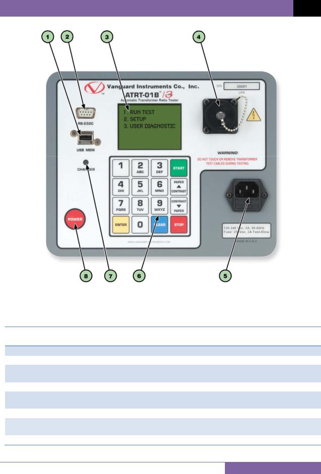
1.2.3. Controls and Indicators
The ATRT-01 S3 and ATRT-01B S3 controls and indicators are shown in Figure 1 and Figure 2, respectively. A leader line with an index number points to each control and indicator, which is cross-referenced to a functional description in the corresponding table. The purpose of the controls and indicators may seem obvious, but users should familiarize themselves with them before using the ATRT. Accidental misuse of the controls will usually cause no serious harm. Users should also familiarize themselves with the safety summary information found on the front page of this User’s Manual.
6
REV 1 ATRT-01/01B S3 USER’S MANUAL
Figure 1. ATRT-01 S3 Controls and Indicators
Table 3. Functional Descriptions of ATRT-01 S3 Controls and Indicators
|
Item |
|
Panel Markings |
|
Functional Description |
|
|
Number |
|
|
|||
|
|
|
|
|
|
|
|
1 |
|
USB MEM |
|
USB Flash drive interface |
|
2 |
|
RS-232C |
RS-232C computer interface port |
|||
|
3 |
|
|
|
Back-lit LCD screen (128 x 64 pixels), viewable in direct sunlight and low |
|
|
|
|
|
light levels |
|
|
|
|
|
|
|
|
|
4 |
|
|
|
H and X lead connector (16-pin male). |
||
|
|
|
|
|
||
|
5 |
|
|
|
Voltage selection switch |
|
6 |
|
120/240 Vac, 2A, 50-60Hz |
|
Input power connector and fused power switch with third-wire safety |
||
|
Fuse: 250Vac, 3A Fast-Blow |
|
ground. |
|||
|
|
|
|
|||
|
7 |
|
|
|
Rugged alpha-numeric keypad |
|
|
|
|
|
|
|
|
7
ATRT-01/01B S3 USER’S MANUAL REV 1
Figure 2. ATRT-01B S3 Controls and Indicators
Table 4. Functional Descriptions of ATRT-01B S3 Controls and Indicators
Item |
Panel Markings |
Functional Description |
|
Number |
|||
|
|
1USB MEM
2RS-232C
3
4
|
|
120-240 Vac, 2A, 50-60Hz |
|
5 |
|||
|
Fuse: 250Vac, 3A Fast-Blow |
||
6 |
|
||
|
|
||
|
|
|
|
7 |
|
CHARGER |
|
8 |
|
POWER |
USB Flash drive interface
RS-232C computer interface port
Back-lit LCD screen (128 x 64 pixels), viewable in bright sunlight and low light levels
H and X lead connector (16-pin male).
Input power connector
Rugged alpha-numeric keypad
Battery charging indicator. LED lights up when battery is being charged.
Power switch
8

REV 1 ATRT-01/01B S3 USER’S MANUAL
2.0PRE-TEST SETUP
2.1ATRT-01 S3 Operating Voltage
The ATRT-01 S3 can be operated from 120 Vac or 240 Vac. The power voltage can be set using the voltage selector switch on the front panel (see Figure 1, item #5)
2.2ATRT-01B S3 Operating Power
The ATRT-01B S3 is powered by a rechargeable (6 Vdc / 7 AH) sealed lead acid gel battery. The unit can operate continuously for up to 6 hours between charges. It can also be used while charging. Plugging the ATRT-01B S3 into an ac power outlet after the battery is fully charged will not damage the battery.
•It is recommended that the ATRT-01B S3 be plugged into an ac outlet when it is not in use.
NOTES • The ATRT-01B S3 uses the Genesis model NP7-6 battery. It can also be replaced with the Panasonic model LC-R122R2PU battery.
2.3LCD Screen Contrast Control
To increase the LCD screen contrast, press and hold the [ Contrast] key for two seconds. Release the button when the desired contrast level has been reached.
To decrease the LCD screen contrast, press and hold the [ Contrast] key for two seconds. Release the button when the desired contrast level has been reached.
For the ATRT-01B S3, the back-light turns off after 30 seconds of operation to conserve power. Press any key on the keypad to re-light the back-light.
9
ATRT-01/01B S3 USER’S MANUAL REV 1
3.0OPERATING PROCEDURES
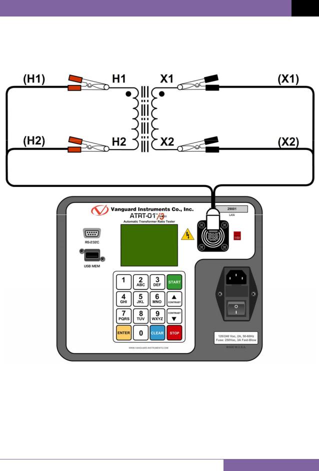
3.1ATRT Transformer Connection Diagrams
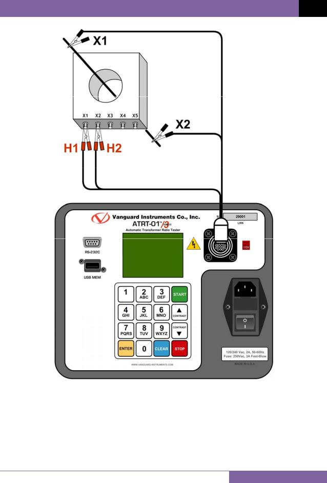
Figure 3. Typical Single-Phase Transformer Connection
10
REV 1 ATRT-01/01B S3 USER’S MANUAL
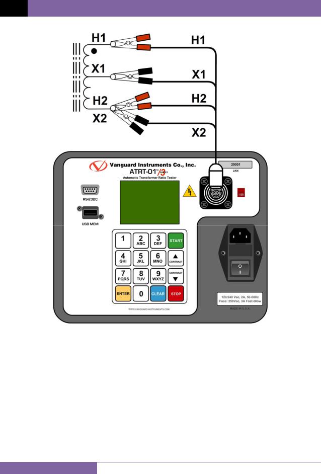
Figure 4. Typical Auto Transformer Connection
11
ATRT-01/01B S3 USER’S MANUAL REV 1
Figure 5. Typical CT Connection
12

REV 1 ATRT-01/01B S3 USER’S MANUAL
Figure 6. Typical Bushing CT Connection on a Single Transformer
13

ATRT-01/01B S3 USER’S MANUAL REV 1
3.2Setting the Test Voltage
The ATRT offers two test voltages, 4 Vac and 40 Vac. The unit always defaults to 40 Vac at power-on. The 4 Vac test voltage can be used in situations where the 40 Vac excitation voltage may saturate the CT’s. To set the test voltage:
a. Turn on the unit and start from the “ START-UP” menu:
1. |
TEST TRANSFORMER |
|
1. |
TEST TRANSFORMER |
|||
|
2. |
SETUP |
|
|
2. |
SETUP |
|
|
3. |
CALCULATOR |
|
3. |
CALCULATOR |
||
|
|
|
|
|
bAT: |
|
|
|
time: |
14:21:34 |
|
time: |
14:21:34 |
||
|
date: |
05/24/11 |
|
date: |
05/24/11 |
||
|
|
|
|
||||
ATRT-01 S3 “START-UP” menu |
ATRT-01B S3 “START-UP” menu |
||||||
Press the [2] key (SETUP).
b. The following screen will be displayed:
1.RECORD ID
2.TEST VOLTAGE
3.PRINT RECORD
4.SAVE/RESTORE RECORD
5.SET TIME
6.SET LANGUAGE
1.RECORD ID
2.TEST VOLTAGE
3.PRINT RECORD
4.SAVE/RESTORE RECORD
5.SET TIME
6.SET LANGUAGE
7.SET 50/60 HZ
ATRT-01 S3 |
ATRT-01B S3 |
Press the [2] key (TEST VOLTAGE).
c.The following screen will be displayed:
1.4 Volts
2.40 VOLTS
Press the [1] key (4 VOLTS) to select 4 volts as the test voltage or press the [2] key (40 VOLTS) to select 40 volts as the test voltage.
14

REV 1 ATRT-01/01B S3 USER’S MANUAL
d. The voltage will be set and the following confirmation message will be displayed:
40 VOLTS SET
Press any key to return to the “START-UP” menu.
15

ATRT-01/01B S3 USER’S MANUAL REV 1
3.3Setting the Date and Time
To set the date and time:
a.Start from the “START-UP” menu:
1.TEST TRANSFORMER
2.SETUP
3.CALCULATOR
time: 14:21:34 date: 05/24/11
Press the [2] key (SETUP).
b.The following screen will be displayed:
1.RECORD ID
2.TEST VOLTAGE
3.PRINT RECORD
4.SAVE/RESTORE RECORD
5.SET TIME
6.SET LANGUAGE
Press the [5] key (SET TIME)
c. The following screen will be displayed:
ENTER DATE
MM-DD-YY
Type in the date using the alpha-numeric keypad. The following screen will be displayed:
ENTER TIME
HH:MM:SS
Enter the time using the alpha-numeric keypad. When the time has been entered, you will be immediately returned to the “START-UP” menu.
16
REV 1 ATRT-01/01B S3 USER’S MANUAL
3.4Setting the Interface Language
Follow the steps below to set the interface language (English, Spanish, or Turkish):
a.Start from the “START-UP” menu:
1.TEST TRANSFORMER
2.SETUP
3.CALCULATOR
time: 14:21:34 date: 05/24/11
Press the [2] key (SETUP).
b.The following screen will be displayed:
1.RECORD ID
2.TEST VOLTAGE
3.PRINT RECORD
4.SAVE/RESTORE RECORD
5.SET TIME
6.SET LANGUAGE
Press the [6] key (SET LANGUAGE).
c.The following screen will be displayed:
1.ENGLISH
2.TURKISH
3.SPANISH
Select the preferred interface language by pressing the corresponding key on the keypad ([1], [2], or [3]). The interface language will be set and a confirmation screen will be displayed as shown below:
ENGLISH SET
Press any key to return to the “START-UP” menu.
17

ATRT-01/01B S3 USER’S MANUAL REV 1
3.5Setting the Frequency (ATRT-01B S3 Only)
Follow the steps below to set the preferred frequency (50 or 60 Hz):
a.Start from the “START-UP” menu:
1.TEST TRANSFORMER
2.SETUP
3.CALCULATOR
bAT:  time: 14:21:34 date: 05/24/11
Press the [2] key (SETUP).
b.The following screen will be displayed:
1.RECORD ID
2.TEST VOLTAGE
3.PRINT RECORD
4.SAVE/RESTORE RECORD
5.SET TIME
6.SET LANGUAGE
7.SET 50/60 HZ
Press the [7] key (SET 50/60 HZ).
c.The following screen will be displayed:
1.60 Hz
2.50 hz
Select the preferred frequency by pressing the corresponding key on the keypad ([1] or [2]). The frequency will be set and a confirmation screen will be displayed as shown below:
60 hz set
Press any key to return to the “START-UP” menu.
18

REV 1 ATRT-01/01B S3 USER’S MANUAL
3.6Performing Tests
3.6.1. Entering Test Record Header Information
You can enter the test record header information before performing tests. The record header includes identifying information such as the company, station, circuit, manufacturer, etc. Once the header information has been set, it will apply to all subsequent test records. Follow the steps below to enter the test header information:
a.Start from the “START-UP” menu:
1.TEST TRANSFORMER
2.SETUP
3.CALCULATOR
time: 14:21:34 date: 05/24/11
Press the [2] key (SETUP).
b.The following screen will be displayed:
1.RECORD ID
2.TEST VOLTAGE
3.PRINT RECORD
4.SAVE/RESTORE RECORD
5.SET TIME
6.SET LANGUAGE
Press the [1] key (RECORD ID).
c. The following screen will be displayed:
COMPANY:
_
↑/↓ TO POSITION
"ENTER" TO ACCEPT
Type the company name using the alpha-numeric keypad.
When pressing a key, the corresponding number on the key will be displayed first. Pressing the key again will display the first letter on the key. Pressing the key again will
display the second letter on the key. For example, to type the letter “A”, you must press the [2] key twice. To erase the character at the cursor position, press the [CLEAR] key. Press the [Contrast ] key to move to the next character. Press the [Contrast ] key to move to the previous character. Press the [ENTER] key when you are done
typing the company name.
19

ATRT-01/01B S3 USER’S MANUAL REV 1
d. The following screen will be displayed:
STATION:
_
↑/↓ TO POSITION
"ENTER" TO ACCEPT
Type the station name using the alpha-numeric keypad and then press the [ENTER] key.
e. The following screen will be displayed:
CIRCUIT:
_
↑/↓ TO POSITION
"ENTER" TO ACCEPT
Type the circuit information using the alpha-numeric keypad and then press the
[ENTER] key.
f. The following screen will be displayed:
MANUFACTURER:
_
↑/↓ TO POSITION
"ENTER" TO ACCEPT
Type the manufacturer name using the alpha-numeric keypad and then press the
[ENTER] key.
20

REV 1 ATRT-01/01B S3 USER’S MANUAL
g. The following screen will be displayed:
MODEL:
_
↑/↓ TO POSITION
"ENTER" TO ACCEPT
Type the transformer’s model information using the alpha-numeric keypad and then press the [ENTER] key.
h. The following screen will be displayed:
SERIAL NUMBER:
_
↑/↓ TO POSITION
"ENTER" TO ACCEPT
Type the transformer’s serial number using the alpha-numeric keypad and then press the [ENTER] key.
i.The following screen will be displayed:
KVA RATING:
_
↑/↓ TO POSITION
"ENTER" TO ACCEPT
Type the transformer’s KVA rating using the alpha-numeric keypad and then press the [ENTER] key.
21

ATRT-01/01B S3 USER’S MANUAL REV 1
j.The following screen will be displayed:
OPERATOR:
_
↑/↓ TO POSITION
"ENTER" TO ACCEPT
Type the operator’s name using the alpha-numeric keypad and then press the [ENTER] key. All header information will be saved, and you will be returned to the “START-UP” menu.
22

REV 1 ATRT-01/01B S3 USER’S MANUAL
3.6.2. Testing a Single Phase Transformer
Follow the steps below to test a single phase transformer:
a.Start from the “START-UP” menu:
1.TEST TRANSFORMER
2.SETUP
3.CALCULATOR
time: 14:21:34 date: 05/24/11
Press the [1] key (TEST TRANSFORMER). b. The following screen will be displayed:
XFMR CONFIG:
1.SINGLE PHASE
2.Dy
3.YD
4.DD
5.YY
6.NEXT PAGE
Press the [1] key (SINGLE PHASE).
c. The following screen will be displayed:
NAME PLATE VOLTAGE?
1.yes
2.no
3.use prev data
Option 3 (USE PREV DATA) will be listed only if you had provided name plate voltages for a previous test.
NOTE
1.YES
Press the [1] key (YES) if you would like to enter the transformer name plate voltage values. The following screen will be displayed:
23
 Loading...