


EZCT S2ATM
DIGITAL CURRENT-TRANSFORMER TESTER
USER’S MANUAL
Vanguard Instruments Company, Inc.
1520 S. Hellman Ave.
Ontario, California 91761, USA
TEL: (909) 923-9390 |
March 2014 |
FAX: (909) 923-9391 |
Revision 1 |
|
|

EZCT S2A USER’S MANUAL REV 1
SAFETY SUMMARY
FOLLOW EXACT OPERATING PROCEDURES
Any deviation from the procedures described in this User’s Manual may create one or more safety hazards, may damage the EZCT S2A, or cause errors in the test results. Vanguard Instruments Company, Inc. assumes no liability for unsafe or improper use of the EZCT S2A.
All safety precautions provided in this manual must be observed during all phases of testing including test preparation, test lead connection, actual testing, and test lead disconnection.
SAFETY WARNINGS AND CAUTIONS
The EZCT S2A can produce a voltage up to 1,500 Vac that can cause severe injury and/or equipment damage. Due to this reason, the EZCT S2A shall be used only by trained operators.
The EZCT S2A’s X output terminals are rated to 1,500 Vac working voltage. Any voltage above 1,500 Vac will damage the input circuitry.
All devices under test shall be off-line and fully isolated. Never attempt to test any current transformer still connected to a circuit. All current transformer terminals shall be isolated before conducting any test with the EZCT S2A.
Always ground the EZCT S2A to a substation ground before connecting the test cables to a transformer.
DO NOT MODIFY TEST EQUIPMENT
To avoid the risk of introducing additional or unknown hazards, do not install substitute parts or perform any unauthorized modification to any EZCT S2A test unit. To ensure that all designed safety features are maintained, it is highly recommended that repairs be performed only by Vanguard Instruments Company factory personnel or by an authorized repair service provider. Unauthorized modifications can cause safety hazards and will void the manufacturer’s warranty.
WARNING
Do not remove test leads during a test. Failure to heed this warning can result in electrical shock to personnel and damage to the equipment.
i

REV 1 EZCT S2A USER’S MANUAL
TABLE OF CONTENTS
CONVENTIONS USED IN THIS DOCUMENT ....................................................................... |
1 |
|||
1.0 |
INTRODUCTION.................................................................................................................... |
2 |
||
1.1 |
General Description and Features ................................................................................... |
2 |
||
1.2 |
Furnished Accessories...................................................................................................... |
3 |
||
1.3 |
Technical Specifications ................................................................................................... |
4 |
||
1.4 |
EZCT S2A Controls and Indicators.................................................................................... |
5 |
||
2.0 |
PRE-TEST SETUP ................................................................................................................... |
7 |
||
2.1 |
Operating Voltages .......................................................................................................... |
7 |
||
2.2 |
LCD Screen Contrast Control............................................................................................ |
7 |
||
2.3 |
Printer Paper Control....................................................................................................... |
7 |
||
2.4 |
Printer Paper.................................................................................................................... |
7 |
||
3.0 |
OPERATING PROCEDURES ................................................................................................... |
9 |
||
3.1 |
EZCT S2A Cable Connections ........................................................................................... |
9 |
||
3.2 |
Performing Tests............................................................................................................ |
11 |
||
3.2.1. |
Entering Test Record Header Information ............................................................. |
11 |
||
3.2.2. |
Performing Excitation and Ratio Tests ................................................................... |
14 |
||
3.3 |
Working With Test Records ........................................................................................... |
24 |
||
3.3.1. |
Restoring and Printing a Test Record From Flash EEPROM ................................... |
24 |
||
3.3.2. |
Restoring and Printing a Test Record From a USB Flash Drive .............................. |
29 |
||
3.3.3. |
Printing a Restored Test Record............................................................................. |
32 |
||
3.3.4. |
Printing a Directory of Test Records Stored in the EZCT S2A’s Memory ............... |
34 |
||
3.3.5. |
Erasing Test Records From the Flash EEPROM ...................................................... |
37 |
||
3.3.6. |
Erasing Test Records From a USB Flash Drive ........................................................ |
40 |
||
3.4 |
Working With Test Plans................................................................................................ |
43 |
||
3.4.1. |
Extracting the Test Plan From a Test Record ......................................................... |
43 |
||
3.4.2. |
Printing a Directory of Test Plans Stored in the EZCT S2A’s Memory.................... |
45 |
||
3.4.3. |
Printing a Directory of Test Plans Stored in a USB Flash Drive .............................. |
47 |
||
3.4.4. |
Printing a Test Plan................................................................................................. |
49 |
||
3.4.5. |
Erasing Test Plans From the Flash EEPROM........................................................... |
51 |
||
3.4.6. |
Erasing Test Plans From a USB Flash Drive............................................................. |
54 |
||
3.4.7. |
Loading a Test Plan from the EZCT S2A’s Flash EEPROM....................................... |
57 |
||
3.4.8. |
Loading a Test Plan from a USB Flash Drive ........................................................... |
59 |
||
3.4.9. |
Running a Test Using a Loaded Test Plan............................................................... |
61 |
||
3.4.10. |
Unloading a Test Plan from the Working Memory ................................................ |
66 |
||
4.0 |
CHANGING SETUP PARAMETERS ....................................................................................... |
67 |
||
4.1 |
Setting the Knee Point Marker ...................................................................................... |
67 |
||
4.2 |
Enabling and Disabling the Buried CT in Transformer Delta Option ............................. |
70 |
||
4.2.1. |
Enabling the Buried CT in Transformer Delta Option............................................. |
70 |
||
4.2.2. |
Disabling the Buried CT in Transformer Delta Option............................................ |
71 |
||
4.3 |
Setting the Clock ............................................................................................................ |
75 |
||
4.4 |
Printing Raw Memory Buffer Data................................................................................. |
76 |
||
5.0 DIAGNOSTICS, VERIFICATION, AND TROUBLESHOOTING ................................................. |
78 |
|||
|
|
|
|
|
ii |
|
|
|
|
|
|
|
|
|

|
EZCT S2A USER’S MANUAL |
REV 1 |
5.1 Performing a Diagnostics Test ....................................................................................... |
78 |
|
5.2 Verifying the EZCT S2A’s Vx Sense Circuit Using an External Meter .............................. |
80 |
|
5.3 Verifying the EZCT S2A’s Ix Sense Circuit Using an External Meter ............................... |
81 |
|
5.4 Quickly Verifying the EZCT S2A’s Turns Ratio Circuit..................................................... |
82 |
|
5.5 |
Troubleshooting Guide .................................................................................................. |
83 |
6.0 |
UPGRADING FIRMWARE .................................................................................................... |
84 |
7.0 Appendix A - Calculating Turns Ratio on a Shunt Reactor................................................. |
87 |
|
|
LIST OF TABLES |
|
Table 1. EZCT S2A Technical Specifications .................................................................................... |
4 |
|
Table 2. Functional Descriptions of EZCT S2A Controls and Indicators.......................................... |
6 |
|
Table 3. Descriptions of Tabulated Test Results Elements........................................................... |
22 |
|
Table 4. Description of Test Plan Elements .................................................................................. |
50 |
|
|
LIST OF FIGURES |
|
Figure 1. EZCT S2A Controls and Indicators.................................................................................... |
5 |
|
Figure 2. Typical EZCT S2A Excitation and Ratio Test Cable Connection........................................ |
9 |
|
Figure 3. Bushing CT Connection on Delta Transformer .............................................................. |
10 |
|
Figure 4. Bushing CT Connection on Y Transformer ..................................................................... |
10 |
|
Figure 5. Typical EZCT S2A Tabulated Report Printout................................................................. |
21 |
|
Figure 6. Typical EZCT S2A Graphic Report................................................................................... |
23 |
|
Figure 7. Typical Internal Test Record Directory Printout ............................................................ |
36 |
|
Figure 8. Typical EZCT S2A Flash EEPROM Test Plan Directory Printout ...................................... |
46 |
|
Figure 9. Typical USB Flash Drive Test Plan Directory Printout .................................................... |
48 |
|
Figure 10. Typical Test Plan Printout ............................................................................................ |
50 |
|
Figure 11. Graphic Report Showing Knee Point Marker............................................................... |
69 |
|
Figure 12. Buried CT in a Delta Transformer Illustration 1 ........................................................... |
73 |
|
Figure 13. Buried CT in a Delta Transformer Illustration 2 ........................................................... |
73 |
|
Figure 14. Sample Raw Data Printout........................................................................................... |
77 |
|
Figure 15. EZCT S2A Vx Verification Test Connections.................................................................. |
80 |
|
Figure 16. EZCT S2A Ix Verification Test Connections ................................................................... |
81 |
|
Figure 17. EZCT S2A Turns Ratio Verification Test Connections................................................... |
82 |
|
Figure 18 ....................................................................................................................................... |
87 |
|
Figure 19 ....................................................................................................................................... |
88 |
|
Figure 20 ....................................................................................................................................... |
89 |
|
Figure 21 ....................................................................................................................................... |
90 |
|
Figure 22 ....................................................................................................................................... |
91 |
|
Figure 23 ....................................................................................................................................... |
92 |
|
Figure 24 ....................................................................................................................................... |
93 |
|
Figure 25 ....................................................................................................................................... |
93 |
|
|
|
iii |

REV 1 EZCT S2A USER’S MANUAL
CONVENTIONS USED IN THIS DOCUMENT
This document uses the following conventions:
•A key or switch on the EZCT S2A is indicated as [KEY] and [SWITCH].
•Menu options are referenced as (MENU OPTION).
•Screen and menu names are referenced as “SCREEN/MENU NAME”.
•The terms “test record” and “test shot” are used interchangeably.
•EZCT S2A LCD screen output is shown as:
1.OPTION 1
2.OPTION 2
3.OPTION 3
4.OPTION 4
5.OPTION 5
•When instructions are provided, the menu item that should be selected is shown in bold as shown below (option 3 should be selected):
1.OPTION 1
2.OPTION 2
3.OPTION 3
4.OPTION 4
5.OPTION 5
•Warning messages are indicated as:
Warning message
WARNING
•Important notes are indicated as:
Note details
NOTE
1

EZCT S2A USER’S MANUAL REV 1
1.0INTRODUCTION
1.1General Description and Features
The EZCT S2A is Vanguard’s third-generation, microprocessor-based, current transformer test set. The EZCT S2A can perform the current transformer (CT) excitation, CT current-ratio, and winding polarity tests automatically. The EZCT S2A automatically raises and lowers the excitation test voltage without any operator intervention. With up to 1500 Vac excitation test voltage available, the EZCT S2A can easily perform excitation tests on very large CT’s.
Excitation Test
The CT excitation test is performed using the ANSI/IEEE C57.13.1, IEC 60044-1 test method. The test voltage range for the CT excitation test (50 Vac, 250 Vac, 500 Vac, or 1500 Vac) can be selected, and then the test voltage is raised and lowered automatically by the EZCT S2A. The test voltage and current data are collected and stored in the unit’s internal memory. Up to 10 CT excitation and current-ratio tests can be stored in one test record. IEEE-30, IEEE-45, ANSI/IEC 60044-1 (10/50) knee point voltages are also calculated and printed on the test report. Once the test is completed, test results can be printed and excitation curves can be plotted on the built-in 4.5-inch wide thermal printer.
CT Ratio and Polarity Tests
The EZCT S2A determines the CT current-ratio using the ANSI/IEEE C57.12.90 measurement method. A test voltage is applied to the CT’s secondary terminals and the induced voltage is measured through the CT’s H1 and H2 terminals. The CT current-ratio and polarity are displayed on the screen and stored in memory. The current-ratio measuring range is from 0.8 to 5,000. The CT winding polarity is displayed as a “+” sign (in-phase) or a “-” sign (out-of-phase) and is annotated with the phase angle in degrees.
User Interface and Display
The EZCT S2A features a back-lit LCD screen (240 x 128 dot graphic) that is viewable in both bright sunlight and low-light levels. A rugged, alpha-numeric, membrane keypad is used to control the unit.
Built-in Thermal Printer
A built-in 4.5-inch wide thermal printer can print the current transformer test report and plot the excitation curves.
2

REV 1 EZCT S2A USER’S MANUAL
Test Record Header Information
The test record header information can include the company name, substation name, circuit ID, manufacturer, CT serial number, operator’s name, and test record comments. In addition to the test record header, a 20-character test description for each test in the record can also be entered.
Internal Test Record Storage Capacity
The EZCT S2A can store up to 140 test records in Flash EEPROM. Each test record may contain up to 10 excitation curves, current-ratio readings, and winding polarity readings. Test records can be recalled and printed on the built-in thermal printer.
Internal Test Plan Storage Capacity
The EZCT S2A can store up to 128 CT test plans in Flash EEPROM. A test plan defines the excitation test voltage and current selection, CT nameplate ratio, and CT winding terminal connection instructions for each test. Up to 10 test definitions can be stored in each test plan. The use of a test plan greatly simplifies the CT testing process since it also provides instructions for making the proper CT cable connections. Test plans can be created on the EZCT S2A itself or created on a PC and downloaded to the EZCT S2A via the unit’s built-in RS-232C or USB port.
External Data Storage
The EZCT S2A features a standard USB Flash drive interface that makes it very convenient to store and transfer test records and test plans. By plugging in a USB Flash drive, you can quickly transfer your test records and test plans between a computer and the EZCT S2A without the need to connect the unit to the computer.
Computer Interface
The EZCT S2A can be used as a stand-alone unit or can be computer-controlled via the built-in RS-232C or USB interfaces. A Windows® XP/Vista-based Current Transformer Analysis software application is provided with each EZCT S2A. This software can be used to retrieve test records from the EZCT S2A, create test plans, download test plans to the EZCT S2A, and can also be used to run CT tests from the PC. Tabulated test records can be exported in Microsoft® Excel format.
1.2Furnished Accessories
The EZCT S2A comes furnished with the following:
•1 Power Cord
•2 20-foot X Cable Sets
•1 35-foot H Cable Set
•One RS-232C serial cable
•One USB cable
•Ground Cables
•Cable carrying duffel bag
3

EZCT S2A USER’S MANUAL REV 1
1.3Technical Specifications
Table 1. EZCT S2A Technical Specifications
TYPE Portable current transformer test set
PHYSICAL SPECIFICATIONS 16.8”W x 12.6”H x 12”D (42.7 cm x 32 cm x 26.9 cm); Weight: 55 lbs (25 kg) INPUT POWER 100 – 120 Vac or 200 – 240 Vac (factory pre-set), 50 Hz/60 Hz
MEASUREMENT METHOD ANSI/IEEE C57.12.90, IEC 60044-1 and ANSI/IEEE C57.13.1 standards
TEST OUTPUT VOLTAGES 0 – 50 Vac @ 10A max, 0 – 250 Vac @ 10A max 0 – 500 Vac @ 5A max, 0 – 1500 Vac @ 1.2A max
VOLTAGE READING RANGE 0 – 2,200 Vac; Accuracy: ±1.0% of reading, ±1 volt
CURRENT READING RANGE 0 – 10A; Accuracy: ±1.0% of reading, ±0.02A
CURRENT-RATIO RANGE 0.8 – 999: 0.1%, 1000 – 1999: 0.3%, 2000 – 5000: 1%
PHASE ANGLE 0 - 360 degrees; Accuracy: ±1.0 degree
MEASUREMENT
DISPLAY Back-lit LCD Screen (240 x 128 dot graphic; 114mm x 64mm); viewable in bright sunlight and low-light levels
PRINTER Built-in 4.5-inch wide thermal printer
COMPUTER INTERFACES One RS-232C port (115k baud), one USB port
EXTERNAL DATA STORAGE One USB Flash drive interface port (Flash drive not included)
PC SOFTWARE Windows® XP/Vista-based CT Analysis software is included with purchase price
INTERNAL TEST RECORD Stores 140 test records. Each test record may contain up to 10 sets of STORAGE excitation, resistance and ratio data
INTERNAL TEST PLAN Stores 128 test plans. Each test plan can store 10 excitation test voltage and STORAGE current settings
SAFETY Designed to meet UL 61010A-1 and CAN/CSA C22.2 No. 1010.1-92 standards
ENVIRONMENT Operating: -10˚ to 50˚ C (15˚F to +122˚ F); Storage: -30˚ C to 70˚ C (-22˚F to +158˚ F)
HUMIDITY (MAX) 90% RH @ 40˚ C (104˚ F) non-condensing
ALTITUDE (MAX) 2000m (6562 ft) to fully safety specifications
CABLES Two 20-foot X cable sets, One 35-foot H cable set, power cord, One cablecarrying duffel bag
WARRANTY One year on parts and labor
The above specifications are valid at nominal operating voltage and at a temperature of 25°C (77°F). Specifications may change without prior notice.
NOTE
4

REV 1 EZCT S2A USER’S MANUAL
1.4EZCT S2A Controls and Indicators
The EZCT S2A’s controls and indicators are shown in Figure 1 below. A leader line with an index number points to each control and indicator, which is cross-referenced to a functional description in Table 2. The table describes the function of each item on the control panel. The purpose of the controls and indicators may seem obvious, but users should become familiar with them before using the EZCT S2A. Accidental misuse of the controls will usually cause no serious harm. Users should also be familiar with the safety summary found on the front page of this User’s Manual.
Figure 1. EZCT S2A Controls and Indicators
5

EZCT S2A USER’S MANUAL REV 1
Table 2. Functional Descriptions of EZCT S2A Controls and Indicators
Item |
|
Panel Markings |
|
Functional Description |
Number |
|
|
||
|
|
|
|
Current transformer excitation voltage connector. The EZCT S2A’s X output |
1 |
|
X |
|
terminal is rated to 1500 Vac working voltage. Any voltage above 1500 Vac |
|
|
|
|
will damage the input circuitry. |
2 |
|
H |
|
Current transformer primary input test cable connector. |
3 |
|
|
|
Built-in 4.5-inch wide thermal printer. |
4 |
|
110-120 Vac, |
|
Power switch with built-in circuit breaker. |
|
12A, 50-60Hz |
|
|
|
|
|
|
|
|
5 |
|
|
|
Power receptacle. |
6 |
|
GROUND |
|
Ground terminal. |
|
|
|
|
|
7 |
|
|
|
Back-lit LCD Screen (240 x 128 dot graphic; 114mm x 64mm). |
|
|
|
|
|
8RS-232C RS-232C PC interface. Baud rate is set for 115KB, 8 data bits, 2 stop bits.
|
9 |
|
USB PC |
USB PC interface. |
10 |
|
|
Rugged alpha-numeric keypad. |
|
|
11 |
|
USB MEM |
USB Flash drive interface port |
12 |
|
HIGH VOLTAGE |
Test voltage presence indicator. |
|
|
PRESENT |
|
||
|
|
|
|
|
|
13 |
|
EMERGENCY |
Emergency turn off switch. |
|
|
TURN OFF |
|
|
|
|
|
“PUSH” |
|
|
|
|
|
|
6
REV 1 EZCT S2A USER’S MANUAL
2.0PRE-TEST SETUP
2.1Operating Voltages
The EZCT S2A’s operating voltage is preset at the factory for 100-120 Vac, 50/60 Hz or 200-240 Vac, 50/60 Hz.
2.2LCD Screen Contrast Control
To increase the LCD screen contrast, press and hold the [PAPER Contrast] key for two seconds. Release the button when the desired contrast level has been reached.
To decrease the LCD screen contrast, press and hold the [PAPER Contrast] key for two seconds. Release the button when the desired contrast level has been reached.
2.3Printer Paper Control
To advance the thermal printer paper, press and release the [PAPER Contrast] key.
To retract the thermal printer paper, press and release the [PAPER Contrast] key.
2.4Printer Paper
The EZCT S2A’s built-in thermal printer uses 4.5-inch wide thermal paper for printing test results. To maintain the highest print quality and to avoid paper jams, the use of thermal paper supplied by Vanguard Instruments Company is highly recommended. Additional paper can be ordered from the following sources:
Vanguard Instruments Co, Inc.
1520 S. Hellman Avenue Ontario, CA 91761
Tel: 909-923-9390
Fax: 909-923-9391
Part Number: VIC TP-4 paper
BG Instrument Co.
13607 E. Trent Avenue Spokane, WA 99216 Tel: 509-893-9881 Fax: 509-893-9803
Part Number: VIC TP-4 paper
7

EZCT S2A USER’S MANUAL REV 1
2.5Replacing the Thermal Printer Paper
The roll of thermal paper is housed inside a dispenser underneath the printer cover. To replace the paper, follow the steps below:
•Unscrew the two large printer cover screws and remove the printer cover.
•Remove the leftover thermal paper roll from the paper holder.
•Unroll the new thermal paper roll.
•Feed the thermal paper into the slot between the paper pocket and the rubber roller. The printer will automatically pull the paper under the thermal head.
•Place the paper roll into the paper holder.
•Lift the thermal head and align the thermal paper if necessary.
•Re-install the printer cover.
Thermal paper has a chemical coating on one side of the paper. This side should be facing the thermal print head. Incorrect paper loading may result in blank output on
the thermal paper.
NOTE
The thermal paper will show a red stripe to indicate that the roll is about to run out of paper.
2.6Computer Interface Ports
The EZCT S2A features one USB and one RS-232C PC interface port. A Windows-based “Current Transformer Analysis” software application is supplied with the EZCT S2A. For further information, please see the Software User’s Manual.
8
REV 1 EZCT S2A USER’S MANUAL
3.0OPERATING PROCEDURES
3.1EZCT S2A Cable Connections
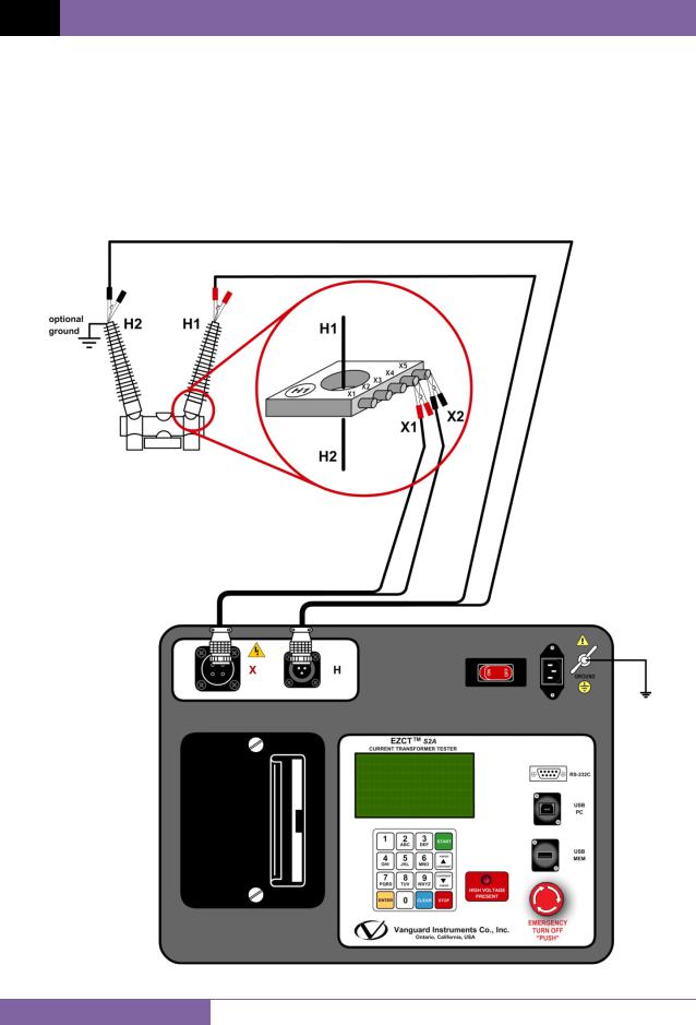
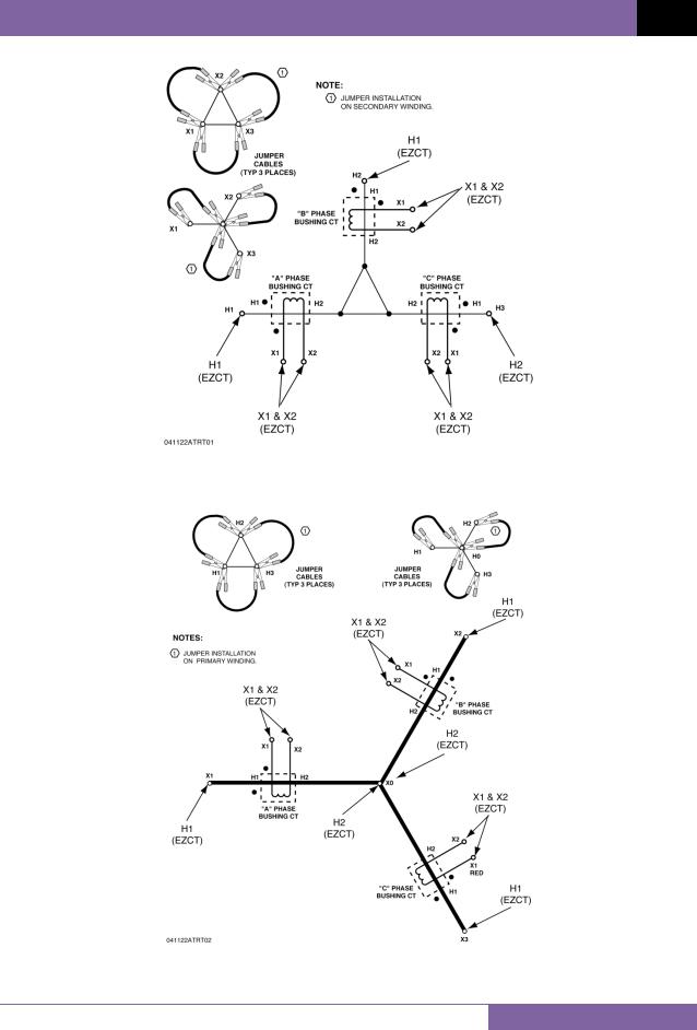
Always connect the EZCT S2A to the substation ground before connecting any test cables. The X cable connections are required to run the current transformer excitation test. The H and X cable connections are required to run the transformer turns-ratio test. A typical excitation and ratio test connection is shown in Figure 2. Transformer bushing CT connections for Delta and Y transformers are shown in Figure 3 and Figure 4, respectively.
Figure 2. Typical EZCT S2A Excitation and Ratio Test Cable Connection
9
EZCT S2A USER’S MANUAL REV 1
Figure 3. Bushing CT Connection on Delta Transformer
Figure 4. Bushing CT Connection on Y Transformer
10

REV 1 EZCT S2A USER’S MANUAL
3.2Performing Tests
3.2.1. Entering Test Record Header Information
You can enter the test record header information before performing tests. The record header includes identifying information such as the company, station, circuit, model number, etc. Once the header information has been entered, it will apply to all subsequent test records. To enter the header information:
a.When the unit is turned on and the firmware has been loaded, you will be presented with the “START-UP” menu as shown below:
1. |
RUN TEST |
02/14/10 |
2. |
SETUP |
10:14:25 |
3.TEST PLANS
4.DIAGNOSTIC
Press the [2] key (SETUP).
b.The following screen will be displayed:
1.RECORD ID
2.PRINT RECORD
3.RECORD DIRECTORY
4.SAVE/RES RECORD
5.ERASE RECORD
6.NEXT PAGE
Press the [1] key (RECORD ID)
c. The following screen will be displayed:
COMPANY:
vanguard
↑↓ TO POSITION "enter" to accept
Type the company name using the alpha-numeric keypad.
When pressing a key, the corresponding number on the key will be displayed first. Pressing the key again will display the first letter on the key. Pressing the key again will
display the second letter on the key. For example, to type the letter “A”, you must press the [2] key twice. To erase the character at the cursor position, press the [CLEAR] key. Press the [PAPER Contrast] key to move to the next character. Press the [PAPERContrast] key to move to the previous character. Press the [ENTER] key when you
are done typing the company name.
11

EZCT S2A USER’S MANUAL REV 1
d. The following screen will be displayed:
STATION:
LAB
↑↓ TO POSITION "enter" to accept
Type the station name using the alpha-numeric keypad and then press the [ENTER] key.
e. The following screen will be displayed:
CIRCUIT:
CIRCUIT 1
↑↓ TO POSITION "enter" to accept
Type the circuit information using the alpha-numeric keypad and then press the
[ENTER] key.
f. The following screen will be displayed:
MANUFACTURER:
ABB
↑↓ TO POSITION "enter" to accept
Type the manufacturer name using the alpha-numeric keypad and then press the
[ENTER] key.
g. The following screen will be displayed:
MODEL:
↑↓ TO POSITION "enter" to accept
Type the model information using the alpha-numeric keypad and then press the
[ENTER] key.
12

REV 1 EZCT S2A USER’S MANUAL
h. The following screen will be displayed:
SERIAL NUMBER:
↑↓ TO POSITION "enter" to accept
Type the serial number using the alpha-numeric keypad and then press the [ENTER] key.
i.The following screen will be displayed:
COMMENTS:
no comment
↑↓ TO POSITION "enter" to accept
Enter any relevant comments using the alpha-numeric keypad and then press the
[ENTER] key.
j.The following screen will be displayed:
OPERATOR:
TA
↑↓ TO POSITION "enter" to accept
Type the operator’s name using the alpha-numeric keypad and then press the [ENTER] key. All header information will be saved, and you will be returned to the “START-UP” menu.
13

EZCT S2A USER’S MANUAL REV 1
3.2.2. Performing Excitation and Ratio Tests
The following procedure describes the general steps for performing excitation and ratio tests.
a.When the EZCT S2A is turned on, it will first go through a start-up cycle and load the firmware. Then the “START-UP” menu will be displayed as shown below:
1. |
RUN TEST |
02/14/10 |
2. |
SETUP |
10:24:25 |
3.TEST PLANS
4.DIAGNOSTIC
Press the [1] key (RUN TEST) to start a test.
b.The following screen will be displayed:
1.EXCITATION & RATIO
2.excitation only
3.ratio only
Select the test type by pressing the corresponding key ([1] - [3])
c. The following screen will be displayed:
SELECT TAP:
1.X1-X2
2.X1-X3
3.X1-X4
4.X1-X5
5.NEXT PAGE
Select the tap connection by pressing the corresponding key ([1] - [4]). If the tap connection is not listed, press the [5] key to view the next page of options.
d. The following screen will be displayed:
HOOK CABLES TO CT: X1 CABLE TO CT-X1 X2 CABLE TO CT-X2 "ENTER" TO CONTINUE
14
REV 1 EZCT S2A USER’S MANUAL
The cable connection information displayed depends on your selection in step c.
NOTE
Press the [ENTER] key to continue.
e. If the selected test included an excitation test, the following screen will be displayed:
SELECT VOLTAGE RANGE:
1.50V
2.250V
3.500V
4.1500V
Select the test voltage range by pressing the corresponding key ([1] - [4]).
f. If the selected test included an excitation test, the following screen will be displayed:
SET TEST CURRENT:
1.0.2A
2.0.5A
3.1A
4.2A
5.5A
6.10A
Select the maximum test current for the excitation test by pressing the corresponding key ([1] - [6]).
Most CT’s will saturate before the excitation current reaches 1A. To reduce stress on CT’s, a maximum test current of 1A is recommended.
NOTE
g. If the selected test included a ratio test, the following screen will be displayed:
XFMR NAME PLATE RAT.
1.YES
2.NO
1.YES
Press the [1] key if you would like to enter the CT nameplate values. The following screen will be displayed:
15

EZCT S2A USER’S MANUAL REV 1
ENTER PLATE RATIO:
0 :
Type the first number using the keypad.
You can press the [CLEAR] key to restart a field entry if necessary.
Press the [ENTER] key. The following screen will be displayed:
ENTER PLATE RATIO:
80 : 0.0
Type the second number using the keypad. The screen will be updated as shown:
ENTER PLATE RATIO:
80 : 1.0
Press the [ENTER] key. Continue to step h.
2.NO
Press the [2] key if you do not want to enter the CT nameplate values. Continue to step h.
h.The following screen will be displayed:
ENTER TEST 1 NOTE:
_
↑↓ to position "ENTER" TO ACCEPT
Use the alpha-numeric keys on the keypad to enter a test note. The test note field is 20 characters long. One test note can be saved for each test.
16
REV 1 EZCT S2A USER’S MANUAL
When pressing a key, the corresponding number on the key will be displayed first. Pressing the key again will display the first letter on the key. Pressing the key again will
display the second letter on the key. For example, to type the letter “A”, you must press the [2] key twice. To erase the character at the cursor position, press the [CLEAR] key. Press the [PAPER Contrast] button to move to the next character. Press the [PAPER Contrast] key to move to the previous character. Press the [ENTER] key
when you are done typing the note.
i.The following screen will be displayed:
TEST 1 parameters: 1500V 1.0A x1-x2
"START" to begin
Press the [START] key to begin running the test.
j.If the selected test included an excitation test, the following screen will be displayed:
CABLES |
ENERGIZED! |
||
1500V |
1.0A |
x1-x2 |
|
I |
= |
0.6810 AMPS |
|
V |
= |
61.0 |
VAC |
|
|
|
|
The “HIGH VOLTAGE PRESENT” light will be illuminated to indicate that high voltage is present.
NOTE
k. If the selected test included a ratio test, the following screen will be displayed:
RATIO TEST
Vx = 39.9 Vh = 0.4984
I = 0.1324 RAT=+80.058
17
EZCT S2A USER’S MANUAL REV 1
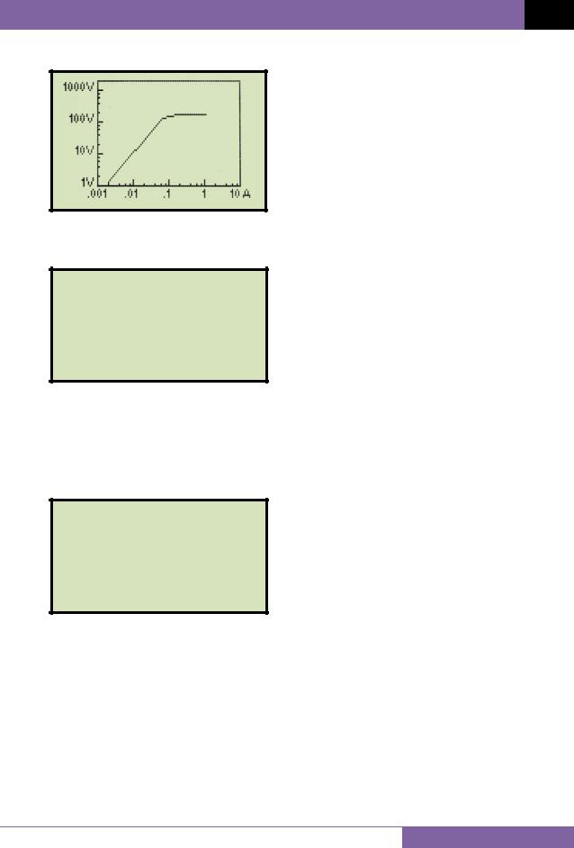
When the testing is finished, the final results graph will be displayed:
Press any key on the keypad to continue.
l.The following screen will be displayed:
print test results?
1.YES
2.NO
Press the [1] key (YES) if you would like to print the test results. The test results will be printed on the thermal printer. A typical EZCT S2A tabulated test report printout is shown in Figure 5. A typical graphic report is shown in Figure 6.
Press the [2] key (NO) if you do not want to print the test results.
m. The following screen will be displayed:
KEEP THIS TEST?
1.YES
2.NO
Press the [1] key (YES) to keep the test results.
18

REV 1 EZCT S2A USER’S MANUAL
n. The following screen will be displayed:
TEST 1 SAVED
Press any key to continue.
o. The following screen will be displayed:
RUN ANOTHER TEST?
1.YES
2.NO
Press the [2] key (NO).
p. The following screen will be displayed:
SAVE THIS RECORD?
1.YES
2.NO
Press the [1] key (YES) to save the record.
The following screen will be displayed momentarily:
SAVING RECORD...
PLEASE WAIT...
19

EZCT S2A USER’S MANUAL REV 1
q. The following confirmation screen will then be displayed:
RECORD NUMBER 1 has been saved!
The test record number is automatically assigned to each test record stored in the EZCT S2A’s Flash EEPROM.
NOTE
Press any key to return to the “START-UP” menu.
20

REV 1 EZCT S2A USER’S MANUAL
Figure 5. Typical EZCT S2A Tabulated Report Printout
21

EZCT S2A USER’S MANUAL REV 1
Table 3. Descriptions of Tabulated Test Results Elements
Item |
Description |
|
Number |
||
|
1Test record header information.
2The X terminals (taps) that were selected for this test.
3 Test note for this particular test. The test note can be up to 20-characters long.
4Recorded excitation current readings on the CT secondary winding.
5 Recorded excitation test voltages applied to the CT secondary winding.
6Impedance calculated at each data point.
7The voltage, current, and impedance data points recorded on the graph grid-marks.
8ASA 10/50 knee point voltage and excitation current
(This is equivalent to the IEC 10/50 and ANSI 10/50 knee point voltage and excitation current)
9 IEEE 30° knee point voltage and excitation current.
10IEEE 45° knee point voltage and excitation current.
11CT nameplate turns ratio.
12Measured turns ratio.
13Turns ratio percentage error.
14Polarity of the CT.
15Measured phase angle.
16Excitation voltage used in CT turns ratio test.
17Excitation current in turns ratio test.
22
REV 1 EZCT S2A USER’S MANUAL
Knee Point Marker
Figure 6. Typical EZCT S2A Graphic Report
23

EZCT S2A USER’S MANUAL REV 1
3.3Working With Test Records
3.3.1. Restoring and Printing a Test Record From Flash EEPROM
You can restore a test record from the EZCT S2A’s Flash EEPROM to the working memory. You can then print the restored test record on the unit’s built-in thermal printer. To restore a test record:
a. Start from the “START-UP” menu:
1. |
RUN TEST |
02/16/10 |
2. |
SETUP |
10:24:25 |
3.TEST PLANS
4.DIAGNOSTIC
Press the [2] key (SETUP).
b.The following screen will be displayed:
1.RECORD ID
2.PRINT RECORD
3.RECORD DIRECTORY
4.SAVE/RES RECORD
5.ERASE RECORD
6.NEXT PAGE
Press the [4] key (SAVE/RES RECORD).
c. The following screen will be displayed:
RESTORE RECORD
1.enter record number
2.scroll to select
If you have a USB Flash drive inserted in the EZCT S2A’s “USB MEM” port, the following screen will be displayed instead of the above screen:
NOTE |
1. |
RESTORE |
RECORD |
|
2. |
COPY TO |
THUMB DRIVE |
|
|
|
|
Press the [1] key (RESTORE RECORD).
The following screen will be displayed:
24
REV 1 EZCT S2A USER’S MANUAL
1.INTERNAL STORAGE
2.THUMB DRIVE
Press the [1] key (INTERNAL STORAGE).
The following screen will then be displayed:
RESTORE RECORD
1.enter record number
2.scroll to select
Continue with the steps below.
1.ENTER RECORD NUMBER
If you know the record number that you would like to restore, press the [1] key. The following screen will be displayed:
RESTORE RECORD
NUMBER:
Type the record number using the alpha-numeric keypad and then press the [ENTER] key. The test record’s graph will be displayed as shown below:
Press any key to continue.
25

EZCT S2A USER’S MANUAL REV 1
The following screen will be displayed:
RECORD RESTORED!
PRINT RECORD?
1.YES
2.NO
If you do not want to print the test record, press the [2] key (NO). The test record will be restored to the working memory, and you will be returned to the “STARTUP” menu.
If you would like to print the test record, press the [1] key (YES). Continue to step d.
26
 Loading...