


ATRT-01 S2, ATRT-01B S2, and ATRT-01D S2
SINGLE PHASE TRANSFORMER TURNS-RATIO METERS
USER’S MANUAL
Vanguard Instruments Company, Inc.
1520 S. Hellman Ave.
Ontario, California 91761, USA
TEL: (909) 923-9390 |
July 2010 |
FAX: (909) 923-9391 |
Revision 2 |
|
|

ATRT-01 S2, ATRT-01B S2, AND ATRT-01D S2 USER’S MANUAL REV 2
SAFETY SUMMARY
This manual applies to the ATRT-01 S2, ATRT-01B S2, and ATRT-1D S2 current transformer turns-ratio meters. The operating procedures are virtually the same for all three models, and any differences are clearly described where applicable.
FOLLOW EXACT OPERATING PROCEDURES
Any deviation from procedures described in this User’s Manual may create one or more safety hazards, damage the ATRT-01/01B/01D S2, damage the test transformer, or cause errors in the test results. Vanguard Instruments Company, Inc. assumes no liability for unsafe or improper use of the ATRT-01/01B/01D S2.
SAFETY WARNINGS AND CAUTIONS
The ATRT-01/01B/01D S2 shall be used only by trained operators. All transformers under test shall be off-line and fully isolated. Do not perform test procedures or service unless another person is also present who is capable of rendering aid and resuscitation.
DO NOT MODIFY TEST EQUIPMENT
To avoid the risk of introducing additional or unknown hazards, do not install substitute parts or perform any unauthorized modification to any ATRT-01/01B/01D S2 test unit. To ensure that all designed safety features are maintained, it is highly recommended that repairs be performed only by Vanguard Instruments Company factory personnel or by an authorized repair service provider. Unauthorized modifications can cause safety hazards and will void the manufacturer’s warranty.
WARNING
Do not remove test leads during a test. Failure to heed this warning can result in electrical shock to personnel and damage to the equipment.
i

REV 2 ATRT-01 S2, ATRT-01B S2, AND ATRT-01D S2 USER’S MANUAL |
|
|
|
TABLE OF CONTENTS |
|
CONVENTIONS USED IN THIS DOCUMENT ..................................................................................... |
1 |
|
1.0 |
INTRODUCTION.................................................................................................................... |
2 |
1.1 |
General Description and Features ................................................................................... |
2 |
1.2 |
Technical Specifications ................................................................................................... |
4 |
1.2.1. ATRT-01 S2 Technical Specifications ........................................................................ |
4 |
|
1.2.2. ATRT-01B S2 Technical Specifications ...................................................................... |
5 |
|
1.2.3. ATRT-01D S2 Technical Specifications...................................................................... |
6 |
|
1.3 |
Controls and Indicators.................................................................................................... |
7 |
2.0 |
PRE-TEST SETUP ................................................................................................................. |
11 |
2.1 |
ATRT-01 S2 Operating Voltages ..................................................................................... |
11 |
2.2 |
ATRT-01B S2 Operating Power ...................................................................................... |
13 |
2.3 |
ATRT-01D S2 Operating Power ...................................................................................... |
13 |
2.4 |
LCD Screen Contrast Control.......................................................................................... |
13 |
3.0 |
OPERATING PROCEDURES ................................................................................................. |
14 |
3.1 |
ATRT Transformer Connection Diagrams ...................................................................... |
14 |
3.2 |
Setting the Test Voltage................................................................................................. |
18 |
3.3 |
Enabling the Computer Interface .................................................................................. |
19 |
3.4 |
Setting the Date and Time ............................................................................................. |
20 |
3.5 |
Performing Tests............................................................................................................ |
21 |
3.5.1. Testing a Single Phase Transformer ....................................................................... |
21 |
|
3.5.2. Testing a Three Phase Transformer ....................................................................... |
24 |
|
3.5.3. Performing a Quick Test ......................................................................................... |
28 |
|
APPENDIX A – TRANSFORMER VECTOR GROUP CODES ............................................................... |
32 |
|
APPENDIX B – Common ANSI Transformer Descriptions ............................................................. |
33 |
|
APPENDIX C – CEI/IEC 60076-1 Transformer Descriptions ........................................................... |
41 |
|
APPENDIX D – Australian Std.2374 Transformer Descriptions..................................................... |
48 |
|
ii

|
ATRT-01 S2, ATRT-01B S2, AND ATRT-01D S2 USER’S MANUAL |
REV 2 |
|
LIST OF TABLES |
|
Table 1. ATRT-01 S2 Technical Specifications ................................................................................. |
4 |
|
Table 2. ATRT-01B S2 Technical Specifications............................................................................... |
5 |
|
Table 3. ATRT-01D S2 Technical Specifications .............................................................................. |
6 |
|
Table 4. |
Functional Descriptions of ATRT-01 S2 Controls and Indicators ...................................... |
8 |
Table 5. |
Functional Descriptions of ATRT-01B S2 Controls and Indicators .................................... |
9 |
Table 6. |
Functional Descriptions of ATRT-01D S2 Controls and Indicators .................................. |
10 |
Table 7. |
ATRT-01 S2 Voltage Selection Jumper Settings .............................................................. |
11 |
Table 8. Pre-programmed Nameplate Voltages ........................................................................... |
31 |
|
|
|
LIST OF FIGURES |
|
Figure 1. ATRT-01 S2 |
Controls and Indicators ................................................................................ |
8 |
|
Figure 2. ATRT-01B S2 Controls and Indicators .............................................................................. |
9 |
||
Figure 3. ATRT-01D S2 Controls and Indicators ............................................................................ |
10 |
||
Figure 4. |
ATRT-01 S2 |
Voltage Selection Jumper Location ............................................................ |
11 |
Figure 5. ATRT-01 S2 |
100 – 120 Vac Jumper Settings................................................................... |
12 |
|
Figure 6. ATRT-01 S2 |
200 – 240 Vac Jumper Settings................................................................... |
12 |
|
Figure 7. |
Typical Single-Phase Transformer Connection .............................................................. |
14 |
|
Figure 8. |
Typical Auto Transformer Connection........................................................................... |
15 |
|
Figure 9. |
Typical CT Connection.................................................................................................... |
16 |
|
Figure 10. Typical Bushing CT Connection on a Single Transformer ............................................ |
17 |
||
Figure 11. Test Results Elements .................................................................................................. |
30 |
||
iii
REV 2 ATRT-01 S2, ATRT-01B S2, AND ATRT-01D S2 USER’S MANUAL
CONVENTIONS USED IN THIS DOCUMENT
This document uses the following conventions:
•The general term “ATRT” is used in this manual to refer to any of the ATRT-01 S2 models (ATRT-01 S2, ATRT-01B S2, and ATRT-1D S2).
•A key, switch, or knob on the ATRT is indicated as [KEY], [SWITCH], [KNOB].
•Menu names are referenced as “MENU NAME”
•ATRT screen output is shown as:
TEXT LINE 1
TEXT LINE 2
TEXT LINE 3
TEXT LINE 4
•Warning messages are indicated as:
Warning message
WARNING
•Important notes are indicated as:
Note details
NOTE
1

ATRT-01 S2, ATRT-01B S2, AND ATRT-01D S2 USER’S MANUAL REV 2
1.0INTRODUCTION
1.1General Description and Features
The ATRT-01 S2 is Vanguard’s third-generation micro-processor-based, single-phase, automatic, transformer-turns-ratio tester. This portable test equipment is offered in three models: the ATRT-01 S2, ATRT-01B S2, and ATRT-01D S2. The ATRT-01 S2 is ac-line powered; the ATRT-01B S2 is ac-line or rechargeable-battery powered, and the ATRT-01D S2 is powered by six D-cells.
The ATRT-01 S2 determines the transformer turns-ratio using the IEEE C57.12.90 measurement method. The transformer turns-ratio is determined by precisely measuring the voltages across the unloaded transformer windings. The ATRT-01 S2’s measuring circuitry self calibrates before each measurement to ensure turns-ratio accuracy.
The ATRT-01 S2 measures turns-ratios ranging from 0.800 to 15,000 and can be used to test voltage regulators, power transformers, current transformers (CT), and Potential Transformers (PT). The ATRT-01 S2 also measures and displays transformer-winding excitation current, and winding polarity. Test results are displayed on a back-lit LCD screen (4 lines by 20 characters).
In addition to measuring a transformer’s turns-ratio, nameplate voltages can also be entered via the keypad, and the ATRT-01 S2 will then display the turns-ratio error as a percentage. This convenient feature eliminates any user-calculation error when testing transformers.
If a 3-phase transformer is being tested, the ATRT-01 S2 will also provide connection information (H and X test probes to transformer bushings) for phases A, B, and C tests. Threephase test results (turns-ratio, excitation current, winding polarity, and percentage error) are displayed on the LCD screen at the end of each test.
User Interface
The ATRT-01 S2 features a back-lit LCD screen (4 lines by 20 characters) that is viewable in both bright sunlight and low-light levels. Displayed test results include turns-ratio, winding polarity, excitation current, and percentage error calculation.
The ATRT-01 S2’s rugged, 16-key membrane keypad is used to select a test and enter the nameplate voltages for turns-ratio percentage error calculation.
Computer Interface
The ATRT-01 S2, ATRT-01B S2 and the ATRT-01D S2 can be used with a PC via the RS-232C interface. Windows® XP/Vista-based software is provided with each unit and can be used to test transformers and to store the test results on the computer. The test results can be retrieved later, in the office for example, for analysis and for printing on an office printer. The test results can also be exported in text or Microsoft® Excel format, thus allowing the results to be used with other PC applications.
The included PC software can also be used to create test plans for specific transformers. A test plan is comprised of the transformer nameplate voltages for each tap setting. Computed turnsratio is based on the nameplate voltages which can be compared to the measured ratio to derive percentage error.
2

REV 2 ATRT-01 S2, ATRT-01B S2, AND ATRT-01D S2 USER’S MANUAL
Battery Power for Exceptional Portability
The ATRT-01B S2 is powered by a 6-Volt, 7 Ampere-hour, lead-acid battery. The high capacity battery, coupled with the ATRT-01B S2’s low power consuming circuitry, allows the unit to be used continuously for up to 6 hours between re-charges. A built-in charger lets the unit be used while the battery is being charged.
The ATRT-01D S2 uses 6 D-cell batteries. Up to 250 tests can be performed with one set of D- cell batteries.
3

ATRT-01 S2, ATRT-01B S2, AND ATRT-01D S2 USER’S MANUAL REV 2
1.2Technical Specifications
1.2.1. ATRT-01 S2 Technical Specifications
Table 1. ATRT-01 S2 Technical Specifications
TYPE |
Portable, automatic, single-phase transformer turns ratio meter |
INPUT POWER |
120 or 240Vac (Selectable), 50/60Hz (See section 2.1) |
|
|
MEASUREMENT METHOD |
ANSI/IEEE C57.12.90 |
RATIO MEASURING RANGE |
0.8 – 15,000 (5-digit resolution) |
|
|
TURNS-RATIO ACCURACY |
0.800 – 1,999 (±0.1%), |
|
2,000 – 3,999 (±0.25%), |
|
4,000 – 15,000 (±1%) |
TEST VOLTAGES |
8 Vac @ 1.0 Amp, 40 Vac @ 0.6 Amp |
EXCITATION READING |
0 – 2 Amperes |
RANGE |
|
CURRENT READING |
±1 milli-amp, ±2% of reading (±1-digit) |
ACCURACY |
|
|
|
DISPLAY |
Back-lit LCD screen (4 lines by 20 characters), viewable in bright sunlight and |
|
low-light levels |
COMPUTER INTERFACE |
One RS-232C (19,200 baud) port |
PC SOFTWARE |
Windows® XP/Vista-based, included with purchase price |
SAFETY |
Designed to meet IEC61010 (1995), UL61010A-1, CSA-C22.2 standards |
|
|
ENVIRONMENT |
Operating: -10˚C to 50˚C (15˚F to 122˚F); Storage: -30˚ C to 70˚C (-22˚F to |
|
158˚F) |
HUMIDITY (MAX) |
90% RH @ 40˚ C (104˚ F) non-condensing |
ALTITUDE (MAX) |
2000m (6562 ft) to fully safety specifications |
CABLES |
One 15-foot single-phase cable, one cable-carrying duffel bag included |
|
|
OPTIONS |
Transportation case |
WARRANTY |
One year on parts and labor |
The above specifications are valid at nominal operating voltage and at a temperature of 25°C (77°F). Specifications may change without prior notice.
NOTE
4

REV 2 ATRT-01 S2, ATRT-01B S2, AND ATRT-01D S2 USER’S MANUAL
1.2.2. ATRT-01B S2 Technical Specifications
Table 2. ATRT-01B S2 Technical Specifications
TYPE |
Portable, automatic, single-phase transformer turns ratio meter |
INPUT POWER |
SLA battery (90–240Vac, 50/60Hz). Delivers up to 6-hours of operation. |
MEASUREMENT METHOD |
ANSI/IEEE C57.12.90 |
RATIO MEASURING RANGE |
0.8 – 15,000 (5-digit resolution) |
TURNS-RATIO ACCURACY |
0.800–1,999 (±0.1%), |
|
2,000–3,999 (±0.25%), |
|
4,000–15,000 (±1.5%) |
TEST VOLTAGES |
8 Vac @ 350 mA, 40 Vac @ 70 mA |
EXCITATION READING |
0 – 2 Amperes |
RANGE |
|
CURRENT READING |
±1 Milli-amp, ±2% of reading (±1-digit) |
ACCURACY |
|
|
|
DISPLAY |
Back-lit LCD screen (4 lines by 20 characters), viewable in bright sunlight and |
|
low-light levels |
COMPUTER INTERFACE |
One RS-232C (19,200 baud) port |
PC SOFTWARE |
Windows® XP/Vista-based, included with purchase price |
SAFETY |
Designed to meet IEC61010 (1995), UL61010A-1, CSA-C22.2 standards |
|
|
ENVIRONMENT |
Operating: -10˚C to 50˚C (15˚F to 122˚F); Storage: -30˚ C to 70˚C (-22˚F to |
|
158˚F) |
HUMIDITY (MAX) |
90% RH @ 40˚ C (104˚ F) non-condensing |
ALTITUDE (MAX) |
2000m (6562 ft) to fully safety specifications |
CABLES |
One 15-foot single-phase cable, one cable-carrying duffel bag included |
|
|
OPTIONS |
Transportation case |
WARRANTY |
One year on parts and labor |
The above specifications are valid at nominal operating voltage and at a temperature of 25°C (77°F). Specifications may change without prior notice.
NOTE
5

ATRT-01 S2, ATRT-01B S2, AND ATRT-01D S2 USER’S MANUAL REV 2
1.2.3. ATRT-01D S2 Technical Specifications
Table 3. ATRT-01D S2 Technical Specifications
TYPE |
Portable, automatic, single-phase transformer turns ratio meter |
INPUT POWER |
6 D Cells (250-test capacity) |
MEASUREMENT METHOD |
ANSI/IEEE C57.12.90 |
RATIO MEASURING RANGE |
0.8 – 15,000 (5-digit resolution) |
TURNS-RATIO ACCURACY |
0.800–1,999 (±0.1%), |
|
2,000–3,999 (±0.25%), |
|
4,000–15,000 (±1.5%) |
TEST VOLTAGES |
8 Vac @ 350 mA, 40 Vac @ 70 mA |
EXCITATION READING |
0 – 2 Amperes |
RANGE |
|
CURRENT READING |
±1 Milli-amp, ±2% of reading (±1-digit) |
ACCURACY |
|
|
|
DISPLAY |
Back-lit LCD screen (4 lines by 20 characters), viewable in bright sunlight and |
|
low-light levels |
COMPUTER INTERFACE |
One RS-232C (19,200 baud) port |
PC SOFTWARE |
Windows® XP/Vista-based, included with purchase price |
SAFETY |
Designed to meet IEC61010 (1995), UL61010A-1, CSA-C22.2 standards |
|
|
ENVIRONMENT |
Operating: -10˚C to 50˚C (15˚F to 122˚F); Storage: -30˚ C to 70˚C (-22˚F to |
|
158˚F) |
HUMIDITY (MAX) |
90% RH @ 40˚ C (104˚ F) non-condensing |
ALTITUDE (MAX) |
2000m (6562 ft) to fully safety specifications |
CABLES |
One 15-foot single-phase cable, one cable-carrying duffel bag included |
|
|
OPTIONS |
Transportation case |
WARRANTY |
One year on parts and labor |
The above specifications are valid at nominal operating voltage and at a temperature of 25°C (77°F). Specifications may change without prior notice.
NOTE
6
REV 2 ATRT-01 S2, ATRT-01B S2, AND ATRT-01D S2 USER’S MANUAL
1.3Controls and Indicators
The ATRT-01 S2, ATRT-01B S2, and ATRT-01D S2 controls and indicators are shown in Figure 1, Figure 2, and Figure 3, respectively. A leader line with an index number points to each control and indicator, which is cross-referenced to a functional description in the corresponding table. The purpose of the controls and indicators may seem obvious, but users should familiarize themselves with them before using the ATRT. Accidental misuse of the controls will usually cause no serious harm. Users should also familiarize themselves with the safety summary information found on the front page of this User’s Manual.
7
ATRT-01 S2, ATRT-01B S2, AND ATRT-01D S2 USER’S MANUAL REV 2
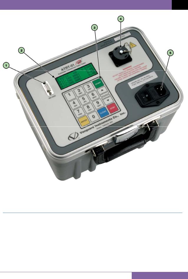
Figure 1. ATRT-01 S2 Controls and Indicators
Table 4. Functional Descriptions of ATRT-01 S2 Controls and Indicators
|
Item |
|
Panel Markings |
|
Functional Description |
|
|
Number |
|
|
|||
|
1 |
|
RS-232C |
|
RS-232C computer interface port. Data rate is set to 19,200 baud, 1 start bit, 8 |
|
|
|
|
data bits, 2 stop bits, and no parity bit. |
|
||
|
|
|
|
|
|
|
2 |
|
|
|
Back-lit LCD screen (20 characters by 4 lines), viewable in bright sunlight and |
||
|
|
|
low-light levels. |
|||
|
|
|
|
|
||
|
3 |
|
|
|
Rugged alpha-numeric keypad. |
|
4 |
|
|
|
H and X lead connector; 16-pin male. |
||
|
5 |
|
120 Vac, 2A, |
|
Input power connector and fused power switch with third-wire safety ground. |
|
|
|
50-60Hz |
|
|
|
|
|
|
|
|
|
|
|
|
|
|
|
|
|
|
8
REV 2 ATRT-01 S2, ATRT-01B S2, AND ATRT-01D S2 USER’S MANUAL
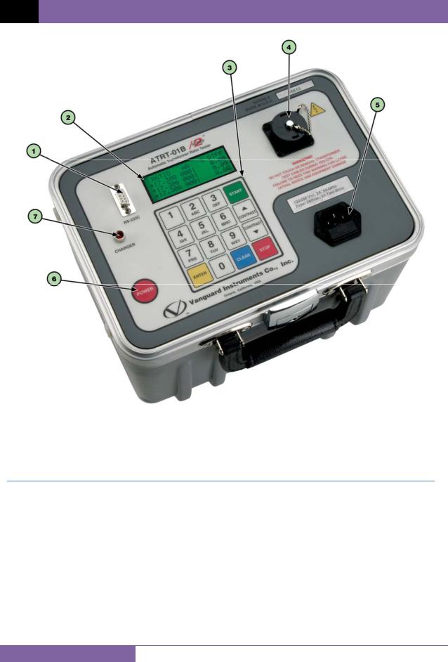
Figure 2. ATRT-01B S2 Controls and Indicators
Table 5. Functional Descriptions of ATRT-01B S2 Controls and Indicators
|
Item |
|
Panel Markings |
|
Functional Description |
|
|
Number |
|
|
|||
|
1 |
|
RS-232C |
|
RS-232C computer interface port. Data rate is set to 19,200 baud, 1 start bit, 8 |
|
|
|
|
data bits, 2 stop bits, and no parity bit. |
|
||
|
|
|
|
|
|
|
2 |
|
|
|
Back-lit LCD screen (20 characters by 4 lines), viewable in bright sunlight and |
||
|
|
|
low-light levels. |
|||
|
|
|
|
|
||
|
3 |
|
|
|
Rugged alpha-numeric keypad. |
|
4 |
|
|
|
H and X lead connector; 16-pin male. |
||
|
5 |
|
120 Vac, 2A, |
|
Input power connector and fused power switch with third-wire safety ground. |
|
|
|
50-60Hz |
|
|
|
|
|
|
|
|
|
|
|
6 |
|
POWER |
|
Power switch, momentary contact. |
||
|
7 |
|
CHARGER |
|
Battery charging indicator. LED lights up when battery is being charged. |
|
|
|
|
|
|
|
|
9
ATRT-01 S2, ATRT-01B S2, AND ATRT-01D S2 USER’S MANUAL REV 2
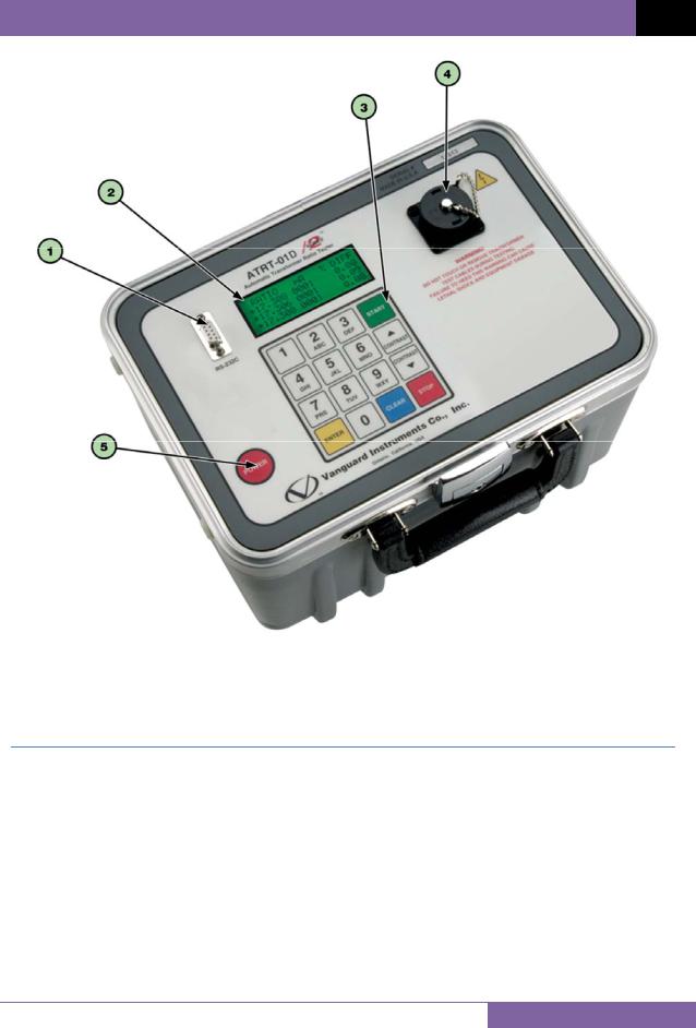
Figure 3. ATRT-01D S2 Controls and Indicators
Table 6. Functional Descriptions of ATRT-01D S2 Controls and Indicators
|
Item |
|
Panel Markings |
|
Functional Description |
|
|
Number |
|
|
|||
|
1 |
|
RS-232C |
|
RS-232C computer interface port. Data rate is set to 19,200 baud, 1 start bit, 8 |
|
|
|
|
data bits, 2 stop bits, and no parity bit. |
|
||
|
|
|
|
|
|
|
2 |
|
|
|
Back-lit LCD screen (20 characters by 4 lines), viewable in bright sunlight and |
||
|
|
|
low-light levels. |
|||
|
|
|
|
|
||
|
3 |
|
|
|
Rugged alpha-numeric keypad. |
|
4 |
|
|
|
H and X lead connector; 16-pin male. |
||
|
5 |
|
POWER |
|
Power switch, momentary contact. |
|
|
|
|
|
|
|
|
10
REV 2 ATRT-01 S2, ATRT-01B S2, AND ATRT-01D S2 USER’S MANUAL
2.0PRE-TEST SETUP
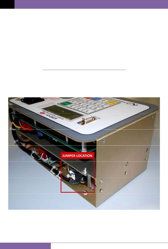
2.1ATRT-01 S2 Operating Voltages
The ATRT-01 S2 is powered by ac line voltage only. The operating voltage is preset at the factory and is selectable between 100-120 Vac, 50/60 Hz or 200-240 Vac, 50/60 Hz. Only the reference transformer requires voltage selection for the different operating voltages. The voltage is set by placing jumper(s) on the transformer (part number 200466-1) as shown in Figure 5 and Figure 6.
Table 7. ATRT-01 S2 Voltage Selection Jumper Settings
|
Voltage |
|
Transformer Jumpers |
|
Selection |
|
|
|
|
|
|
|
100 – 120 Vac |
|
Pin 1 and 3, Pin 2 and 4 |
|
200 – 240 Vac |
|
Pin 2 and 3 |
Figure 4. ATRT-01 S2 Voltage Selection Jumper Location
11

ATRT-01 S2, ATRT-01B S2, AND ATRT-01D S2 USER’S MANUAL REV 2
Figure 5. ATRT-01 S2 100 – 120 Vac Jumper Settings
Figure 6. ATRT-01 S2 200 – 240 Vac Jumper Settings
12

REV 2 ATRT-01 S2, ATRT-01B S2, AND ATRT-01D S2 USER’S MANUAL
2.2ATRT-01B S2 Operating Power
The ATRT-01B S2 is powered by a rechargeable (6 Vdc / 7 AH) sealed lead acid gel battery. The unit can operate continuously for up to 6 hours between charges. It can also be used while charging. Plugging the ATRT-01B S2 into an ac power outlet after the battery is fully charged will not damage the battery.
•It is recommended that the ATRT-01B S2 be plugged into an ac outlet when it is not in use.
NOTES • The ATRT-01B S2 battery can be replaced with the Panasonic model LC-R122R2PU battery.
2.3ATRT-01D S2 Operating Power
The ATRT-01D S2 is powered by six standard D cell batteries. We recommend industrial (1.5 volts) D cells such as the Duracell 1300.
To turn the unit on or off, press and hold the [POWER] switch for 2 seconds.
2.4LCD Screen Contrast Control
To increase the LCD screen contrast, press and hold the [ Contrast] key for two seconds. Release the button when the desired contrast level has been reached.
To decrease the LCD screen contrast, press and hold the [ Contrast] key for two seconds. Release the button when the desired contrast level has been reached.
For the ATRT-01B S2 and ATRT-01D S2, the back-light turns off after 30 seconds of operation to conserve power. Press any key on the keypad to re-light the back-light.
13
ATRT-01 S2, ATRT-01B S2, AND ATRT-01D S2 USER’S MANUAL REV 2
3.0OPERATING PROCEDURES
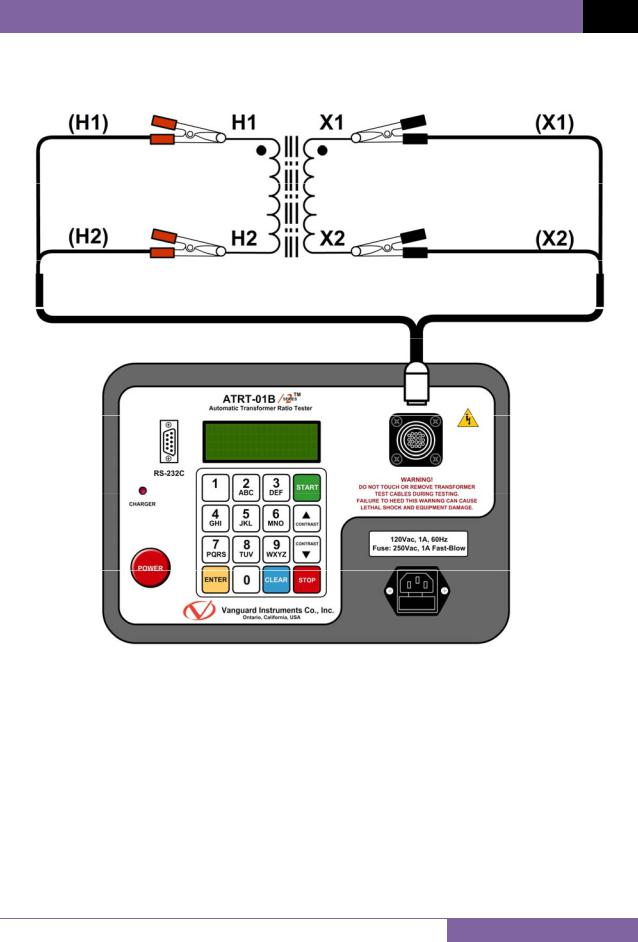
3.1ATRT Transformer Connection Diagrams
Figure 7. Typical Single-Phase Transformer Connection
14
 Loading...