


OPERATING INSTRUCTIONS
for the
CT-6500 Series 2
Digital Circuit Breaker Analyzer
|
Vanguard Instruments Company |
|
1520 South Hellman Avenue |
|
Ontario, California 91761, USA |
|
|
TEL: (909) 923-9390 |
May 2008 |
FAX: (909) 923-9391 |
Rev 2 |

CT-6500 Series 2 Operating Instructions
SAFETY WARNINGS AND CAUTIONS
Only trained operators shall use the device. All circuit breakers under test shall be off line and fully isolated.
DO NOT SERVICE OR TEST ALONE
Do not perform test procedures or service unless another person is also present who is capable of rendering aid and resuscitation.
DO NOT MODIFY TEST EQUIPMENT
Due to the added risk of introducing additional or unknown hazards, do not install substitute parts or perform any unauthorized modifications to any CT-6500 test unit. To ensure that all designed safety features are maintained, it is recommended that repairs be performed only by Vanguard Instruments Company’s factory personnel or by an authorized repair and service center. Unauthorized modifications can cause serious safety hazards and will nullify the manufacturer's warranty.
FOLLOW EXACT OPERATING PROCEDURES
Any deviation from the procedures described in the operator’s manual may create one or more safety hazards, damage the CT-6500, the test circuit breaker or cause errors in the test results. Vanguard Instruments Company, Incorporated assumes no liability for unsafe or improper use of the CT-6500.
WARRANTY
The CT-6500’s warranty is only valid to the original purchaser to be free from defects in material and workmanship for a period of one year. The warranty does not apply to normal wear or damage from misuse, abuse, improper storage, installation, accident, unauthorized repair or alterations.
I

|
CT-6500 Series 2 Operating Instructions |
|
|
Table of Contents |
|
1.0 Introduction ............................................................................................................................. |
7 |
|
2.0 CT-6500 Description............................................................................................................... |
8 |
|
2.1 |
Contact Timing Channels............................................................................................ |
8 |
2.2 |
Analog Voltage Monitoring Channel............................................................................ |
8 |
2.3 |
Digital Voltage Monitoring Channel............................................................................. |
8 |
2.4 |
Trip/Close Current Monitoring ..................................................................................... |
8 |
2.5 |
Travel Transducer Input Channels.............................................................................. |
8 |
2.6 |
Breaker Initiate Capability ........................................................................................... |
8 |
2.7 |
Built-in Thermal Printer ............................................................................................... |
9 |
2.8 |
Computer Interface Capabilities.................................................................................. |
9 |
2.9 |
Timing Records Storage Capabilities.......................................................................... |
9 |
2.10 Diagnostic Capabilities.............................................................................................. |
9 |
|
2.11 CT-6500 Display and Control Switches .................................................................... |
9 |
|
3.0 Test Result Tabulation............................................................................................................ |
9 |
|
3.1 |
Timing Test Measurement Results ............................................................................. |
9 |
3.2 |
Mechanical Measurement Results ............................................................................ |
10 |
3.3 |
Analog Voltage Input Results.................................................................................... |
10 |
3.4 |
Digital Voltage Input Results..................................................................................... |
10 |
3.5 |
Initiate Current Results.............................................................................................. |
10 |
3.6 |
Slow-Close Test Results........................................................................................... |
11 |
4.0 Test Result Graphics ............................................................................................................ |
11 |
|
4.1 |
Thermal Printer Graphic Printout .............................................................................. |
11 |
5.0 CT-6500 Controls and Display.............................................................................................. |
12 |
|
6.0 CT-6500 Analyzer Specifications.......................................................................................... |
15 |
|
7.0 CT-6500 Special Features.................................................................................................... |
17 |
|
7.1 |
CT-6500 Supplied Cables......................................................................................... |
17 |
7.2 |
CT-6500 Operating Voltages .................................................................................... |
18 |
7.3 |
CT-6500 Main Power Switch & Circuit Breaker ........................................................ |
18 |
7.4 |
Initiate Circuit Protection Fuses ................................................................................ |
18 |
7.5 |
CT-6500 Printer and Printer Paper ........................................................................... |
19 |
7.6 |
Replacing CT-6500 Thermal Paper .......................................................................... |
19 |
7.7 |
CT-6500 Printer Paper Control ................................................................................. |
19 |
7.8 |
CT-6500 LCD Contrast Control................................................................................. |
19 |
8.0 Test Hook-up Connections ................................................................................................... |
20 |
|
8.1 |
Contact Cable Hookup.............................................................................................. |
20 |
8.2 |
Initiate Cable Hookup................................................................................................ |
22 |
8.3 |
Analog Voltage Monitor Hookup ............................................................................... |
23 |
8.4 |
Digital Voltage Monitor Hookup................................................................................. |
23 |
8.5 |
External Trigger Input................................................................................................ |
24 |
8.6 |
Digital Transducer Connection.................................................................................. |
25 |
9.0 Operating Procedures........................................................................................................... |
26 |
|
9.1 |
Timing a Circuit Breaker............................................................................................ |
27 |
9.1.1 Timing an OPEN Operation (With No Insertion Resistors) .................................... |
28 |
|
9.1.2 Timing an OPEN Operation with Insertion Resistors ............................................. |
29 |
|
9.1.3 Timing CLOSE-OPEN Operation Using Contact Channel #1 ................................ |
30 |
|
9.1.4 Timing OPEN-CLOSE-OPEN Operation................................................................ |
32 |
|
II

CT-6500 Series 2 Operating Instructions
9.2 |
Printing Tabulated Timing Results Using the Thermal Printer .................................. |
33 |
|
9.2.1 Tabulated Results Interpretation............................................................................ |
35 |
||
9.3 |
Get Graphic Timing Results Using the Thermal Printer ............................................ |
36 |
|
9.4 |
Save Timing Test Records in the EEPROM ............................................................. |
41 |
|
9.5 |
Printing Timing Test Record Directory Stored in the EEPROM ................................ |
42 |
|
9.6 |
Recalling a Timing Test Record................................................................................ |
44 |
|
9.7 |
Deleting a Timing Test Record.................................................................................. |
45 |
|
9.8 |
Test Record Description............................................................................................ |
46 |
|
9.9 |
Computer Interface ................................................................................................... |
48 |
|
9.10 |
Breaker Travel Analysis .......................................................................................... |
49 |
|
9.10.1 Breaker Stroke ..................................................................................................... |
49 |
||
9.10.2 Breaker Over-Travel Distance.............................................................................. |
49 |
||
9.10.3 Breaker Bounce-Back Distance ........................................................................... |
49 |
||
9.10.4 Contact Wipe........................................................................................................ |
49 |
||
9.10.5 Breaker Velocity................................................................................................... |
49 |
||
9.10.6 Analysis Point Selections..................................................................................... |
49 |
||
9.10.7 Analysis Point No.1 (AP1).................................................................................... |
50 |
||
9.10.8 Analysis Point No. 2 (AP2)................................................................................... |
50 |
||
9.10.9 Set-Up Open Analysis Points............................................................................... |
52 |
||
9.11 |
Select English or Metric Measurement Unit. ........................................................... |
54 |
|
9.12 |
Digital Rotary Transducer Selection........................................................................ |
54 |
|
9.13 |
Slow-Close Test...................................................................................................... |
55 |
|
9.14 |
Transducer Self-Test............................................................................................... |
57 |
|
9.15 |
Check Cable Hookup .............................................................................................. |
58 |
|
9.16 |
Set CT-6500 Time and Date ................................................................................... |
59 |
|
9.17 |
Automatic Print Setting............................................................................................ |
60 |
|
9.18 |
Selecting 50 Hz or 60 Hz for Contact Time Reading .............................................. |
61 |
|
9.19 |
CT-6500 Channel Configuration ............................................................................. |
63 |
|
9.20 |
Print Test Record Data............................................................................................ |
64 |
|
9.21 |
Transducer Encoder Filter Setting .......................................................................... |
65 |
|
9.22 |
Contact Filter Setting............................................................................................... |
66 |
|
9.23 |
Running CT-6500s in Tandem ................................................................................ |
68 |
|
10.0 CT-6500 Trouble Shooting Guide....................................................................................... |
69 |
||
III

|
CT-6500 Series 2 Operating Instructions |
|
|
List of Figures |
|
Figure 1.0 |
CT-6500 Control Panel.......................................................................................... |
12 |
Figure 2.0 |
CT-6500 Operating Voltage Setting....................................................................... |
18 |
Figure 3.0 |
Contact Cable Connection..................................................................................... |
20 |
Figure 4.0 |
Series Contact Cable Connection.......................................................................... |
21 |
Figure 5.0 |
DC Trip and DC Close, Initiate Circuit Cable Hook-Up.......................................... |
22 |
Figure 6.0 |
DC Trip and AC Close, Initiate Circuit Cable Hook-Up .......................................... |
22 |
Figure 7.0 |
Voltage Monitoring Cable Hook-Up ....................................................................... |
23 |
Figure 8.0 |
External Trigger Cable Hook-Up............................................................................ |
24 |
Figure 9.0 |
Transducer Connection ......................................................................................... |
25 |
Figure 10.0 |
CT-6500 Operating Steps.................................................................................... |
26 |
Figure 11.0 |
Typical Tabulated Printout of an Open Operation From the Thermal Printer....... |
34 |
Figure 12.0 |
Typical Graphic Result Printed on Thermal Printer.............................................. |
37 |
Figure 13.0 |
Expansion Graph From 0 to 300ms Printed on Thermal Printer .......................... |
38 |
Figure 14.0 |
Graphical Interpretation of an Open Timing Shot ................................................ |
39 |
Figure 15.0 |
Graphical Interpretation of a Close Timing Shot .................................................. |
39 |
Figure 16.0 |
Graphical Interpretations of an Open-Close and a Close-Open Timing Shot ...... |
40 |
Figure 17.0 |
Printout of the Timing Shot Directory From the Thermal Printer.......................... |
43 |
Figure 18.0 |
Typical Slow-Close Test Report .......................................................................... |
56 |
Figure 19.0 |
Typical 50 Hz Tabulated Report .......................................................................... |
62 |
Figure 20.0 |
Typical 60 Hz Tabulated Report .......................................................................... |
62 |
Figure 21.0 CT-6500 Timing Data ........................................................................................... |
64 |
|
Figure 22.0 |
Contact Filter Setting Illustration.......................................................................... |
67 |
IV

|
CT-6500 Series 2 Operating Instructions |
|
|
List of Tables |
|
Table 1.0 |
CT-6500 Controls and Displays .............................................................................. |
13 |
Table 2.0 CT-6500 Cable set.................................................................................................. |
17 |
|
Table 3.0 |
Open Operation With No Insertion Resistors.......................................................... |
28 |
Table 4.0 |
Open Operation With Insertion Resistor ................................................................. |
29 |
Table 5.0 Close-Open Operation Using Contact Channel #1 ................................................. |
31 |
|
Table 6.0 Open-Close-Open Operation Using Delay.............................................................. |
32 |
|
Table 7.0 |
Printing Tabulated Results...................................................................................... |
33 |
Table 8.0 |
Plot Timing Chart .................................................................................................... |
36 |
Table 9.0 Save Timing Test Record In EEPROM................................................................... |
41 |
|
Table 10.0 |
Print Timing Test Record Directory....................................................................... |
42 |
Table 11.0 |
Recalling a Timing Test Record............................................................................ |
44 |
Table 12.0 |
Deleting a Timing Record ..................................................................................... |
45 |
Table 13.0 |
Entering Test Record Identification Header .......................................................... |
46 |
Table 14.0 |
RS-232C Connector Pin Definition ....................................................................... |
48 |
Table 15.0 |
Setting Up "OPEN" Analysis Points Using Distance ............................................. |
52 |
Table 16.0 |
Select English or Metric Procedure....................................................................... |
54 |
Table 17.0 |
Select Rotary Transducer ..................................................................................... |
54 |
Table 18.0 |
Performing a Slow-Close Test .............................................................................. |
55 |
Table 19.0 |
Performing a Transducer Self Test ....................................................................... |
57 |
Table 20.0 Checking the Cable Hookup ................................................................................. |
58 |
|
Table 21.0 Set CT-6500 Time and Date ................................................................................. |
59 |
|
Table 22.0 |
Automatic Print Setting ......................................................................................... |
60 |
Table 23.0 Selecting 50Hz or 60 Hz for Contact Time Reading .............................................. |
61 |
|
Table 24.0 |
Channel Configuration .......................................................................................... |
63 |
Table 25.0 |
Print Test Record Data ......................................................................................... |
64 |
Table 26.0 |
Set Transducer Filter ............................................................................................ |
65 |
Table 27.0 |
Set Contact Filter .................................................................................................. |
66 |
V

CT-6500 Series 2 Operating Instructions |
|
Appendix |
|
APPENDIX A ITE Circuit Breaker model 14.4K Timing Chart................................................... |
71 |
APPENDIX B CLOSE-OPEN Timing Chart for ITE Circuit Breaker Model 14.4K ..................... |
72 |
APPENDIX C CLOSE-OPEN Tabulated Report for ITE Circuit Breaker Model 14.4K.............. |
73 |
APPENDIX D OPEN-CLOSE Timing Chart for ITE Circuit Breaker Model 14.4K ..................... |
74 |
APPENDIX E OPEN-CLOSE Tabulated Report for ITE Circuit Breaker Model 14.4K .............. |
75 |
APPENDIX F SIEMENS TCP Breaker Velocity Calculation ...................................................... |
76 |
APPENDIX G SIEMENS SPS2 Breaker Velocity Calculation ................................................... |
77 |
APPENDIX H CT-6500 SIEMENS SPS2 Test Plan .................................................................. |
78 |
APPENDIX I CT-6500 Transducer Illustration ........................................................................... |
79 |
VI

CT-6500 Series 2 Operating Instructions
1.0 Introduction
The CT-6500 is the fifth generation microprocessor-based, digital time travel circuit breaker analyzer developed by Vanguard Instruments Co. The CT-6500 can fully analyze a utility circuit breaker’s performance by measuring: the contact time, stroke, velocity, over-travel, bounce-back and contact wipe.
The circuit breaker contact motion analysis includes: Open, Close, Open-Close, Close-Open and Open-Close-Open operations. A timing window of one second, ten second or twenty second can be selected. The ten and twenty second windows allow timing of long timing events such as circuit switcher contact activities.
The conventional Time-Travel test mode allows the user to fully analyze the circuit breaker contact time and contact travel information. Additional circuit breaker information such as:
Operating-coil current reading, breaker DC coil power supply voltage reading are also available.
The CT-6500 is available with the following configurations:
CT-6500-3:
-Three Contact-Input channels
-Three Digital Travel Transducer Input channels
-One Analog Voltage Monitor Input channel
-One Digital Voltage Monitor Input channel
-One Trip/Close Current Monitor channel
CT-6500-6:
-Six Contact-Input channels
-Three Digital Travel Transducer Input channels
-One Analog Voltage Monitor Input channel
-One Digital Voltage Monitor Input channel
-One Trip/Close Current Monitor channel
CT-6500-12:
-Twelve Contact-Input channels
-Three Digital Travel Transducer Input channels
-One Analog Voltage Monitor Input channel
-One Digital Voltage Monitor Input channel
-One Trip/Close Current Monitor channel
There are two different modes of operation for the CT-6500 which are Stand Alone Mode and Computer Control Mode. The manual will focus on the Stand Alone Mode. The Computer Control
Mode is covered under the Circuit Breaker Analyzer Software Series 2 manual.
7

CT-6500 Series 2 Operating Instructions
2.0CT-6500 Description
2.1Contact Timing Channels
A breaker's interruption of contacts are timed with the dry-contact input channels. Each contact channel can detect the main contacts and the insertion resistor contact times in milliseconds and cycles.
The CT-6500 applies a test voltage of 35Vdc to each of the contact channels thus allowing an analog to digital converter (A/D) to determine if a close, an open or an insertion resistor was the state of the contact. The CT-6500 records into the memory 20,000 readings from the A/Ds and the transducer position counters. The contact time, circuit breaker stroke and velocity is then derived from the data that was stored in the memory.
NOTE
The CT-6500 can detect insertion resistors ranging from 10 to 7,000 Ohms. Resistances over 7,000 Ohms are detected as an open contact.
2.2 Analog Voltage Monitoring Channel
One analog voltage, input channel, “V1” is dedicated to monitoring the breaker's DC power supply or coil voltages from 0 to 255Vdc or peak Vac.
NOTE
Maximum input voltage is 300Vdc or peak Vac. Recording voltage readings are from 0 to 255Vdc.
2.3 Digital Voltage Monitoring Channel
One digital voltage, input channel, “V2” monitors the status voltage as “ON” or “OFF.” Voltages from 30 to 255Vdc are considered as “ON” status. Voltages less than 30Vdc are considered as
“OFF” status.
2.4 Trip/Close Current Monitoring
A built-in, hall-effect, current sensor measures the trip and close coil current levels and duration. The coil current waveform can be graphically plotted onto a printout. The coil current reading is also printed in the tabulated report. The CT-6500 initiate circuit is capable of carrying up to 30 amperes. Maximum coil current reading is 20 amperes.
2.5 Travel Transducer Input Channels
Each CT-6500 has three digital transducer input channels. The CT-6500 uses up-down counters to sense the breaker’s transducer reading. The CT-6500 travel transducer employs optical encoders to send quadrature signals to the CT-6500’s counters. With the use of digital transducers and counters, the need to set up or calibrate the transducers is eliminated.
The CT-6500 will interface with a linear, a rotary and other special transducers developed by Vanguard Instruments Company. Please refer to Appendix I for more details.
2.6 Breaker Initiate Capability
A built-in, solid-state, initiate device allows the user to operate the circuit breaker from the CT6500. Operational modes include: Open, Close, Open-Close, Close-Open and Open-Close- Open. The multiple operations of: Open-Close, Close-Open and Open-Close-Open can be initiated with a programmable delay time or by sensing the breaker's contact state.
The solid-state switching implemented in the initiate circuitry allows the CT-6500 to switch a
8

CT-6500 Series 2 Operating Instructions
breaker's AC or DC control circuit. . The CT-6500 initiate circuit is capable of carrying up to 30 amperes. Separate 5 Ampere, fast-blow fuses protect each trip and close circuits. An interlock
“ARM” switch action is required by the operator to operate the initiate circuit.
2.7 Built-in Thermal Printer
The breaker's contact analysis results can be printed in both tabular and graphical formats by a built-in, 4.5 inch wide, thermal printer. Refer to paragraph 7.5 for ordering thermal paper.
2.8 Computer Interface Capabilities
Built-in, RS-232C and USB ports allow the CT-6500 to be interfaced with an IBM-compatible personal computer. A Windows XP Circuit Breaker Analyzer software is supplied with each CT-
6500. The software allows the user to:
-Control CT-6500 from a personal computer.
-Retrieve timing records stored in the CT-6500.
-Transfer circuit breaker test plans to CT-6500.
-Recall timing records from a hard drive for reanalysis at an office PC.
2.9Timing Records Storage Capabilities
The CT-6500 uses Electrically Erasable Programmable Read-Only-Memory (EEPROM) to store timing-shot data. Unlike other media, EEPROMs are immune to temperature, shock and humidity. Stored shots can be recalled to reanalyze the test data, to reprint test reports or to transfer data to a personal computer for record keeping. Up to 100 timing records can be stored in the EEPROMs. The number of test records stored in the EEPROMs may vary depending upon the size of the records.
2.10 Diagnostic Capabilities
The CT-6500 is designed with self-diagnostic capability to check the integrity of the electronics. Self testing of the contact cable hook-up and transducers permits the user to examine the CT6500‘s components whenever verification is required.
2.11 CT-6500 Display and Control Switches
An alphanumeric keypad enables the users to operate the CT-6500 and to enter the breaker’s nameplate data such as: the substation name, breaker model and other descriptions. A 4-line by
20-character LCD readout displays user messages and menus. The LCD is back-lighted to allow messages to be viewed in low light conditions.
3.0Test Result Tabulation
3.1Timing Test Measurement Results
In the Time Travel Mode, each CT-6500 contact channel provides the following test results:
-Contact Close time
-Contact Open time
-Insertion Resistor Contact Open and Close times
-Contact Bounce time
-Resistor On time
-Contact Spread time
9
CT-6500 Series 2 Operating Instructions
NOTE
The CT-6500 can detect insertion resistors ranging from 10 to 7,000 Ohms.
Resistances over 7,000 Ohms are detected as an open contact.
3.2 Mechanical Measurement Results
In the Time Travel Mode, the digital transducer channels provide the following test results:
-CB contact stroke
-CB contact over travel
-CB Contact bounce back
-CB Contact wipe
-CB Contact velocity
Breaker contact speed calculations are based upon a contact's travel distance over a period of time, which is defined by the manufacturer's specifications.
NOTE
When the resistor type transducer channel is used, the test results are shown as transducer channel 1.
CB contact mechanical measurement can be shown in “English” or “Metric” units.
3.3 Analog Voltage Input Results
The analog voltage, input channel, “V1” measures the breaker's DC control voltage during an operation. Printed voltage readings include nominal voltage (when the supply voltage has no load) and minimum voltage (when the supply voltage is under load or when a coil is energized).
The “V1” connection allows the user to monitor the DC power supply’s voltage fluctuations during a breaker operation. This feature is effective in detecting breaker power supply problems, which normally can not be seen by using a voltmeter.
NOTE
Printed voltage readings can range from 0 to 255Vdc.
3.4 Digital Voltage Input Results
The digital voltage, input channel, “V2” monitors the voltage status as “ON” or “OFF” conditions and graphs the result. A voltage level above 30Vdc is considered as the “ON” state.
The input channel is dedicated to monitor the breaker’s auxiliary switch action during a breaker operation.
NOTE
The input voltage ranges from 0 to 300Vdc or peak ac.
3.5 Initiate Current Results
The CT-6500 not only plots the trip or close current waveforms, but also prints the steady-state current readings of the trip and close coils during an operation. A typical circuit breaker timing report is shown in Figure 11.0.
10

CT-6500 Series 2 Operating Instructions
3.6 Slow-Close Test Results
A Slow-Close test determines the contact touch distance and penetration by using the travel transducer and dry contact channels. See section 9.13 for Slow-Close test Procedure.
4.0Test Result Graphics
4.1Thermal Printer Graphic Printout
A 4.5 inch wide, built-in, thermal printer can output graphic waveforms of the contact channels, travel curves and actuator-coil currents. Using the Zoom Graphics Mode, the user can enlarge the graphical outputs by specifying the timing zone. Typical graphical results are shown in Figures 12.0 and 13.0.
11

CT-6500 Series 2 Operating Instructions
5.0 CT-6500 Controls and Display
Before using the CT-6500, users should become familiar with all of the controls and display indications. The keypad and display are used to operate the CT-6500. Figure 1.0 represents the control panel and the numbered lines pointing to each control and indicator refer to Table 1.0, which describes the function of each control and indicator.
Figure 1.0 CT-6500 Control Panel
12

|
CT-6500 Series 2 Operating Instructions |
||
|
Table 1.0 CT-6500 Controls and Displays |
||
Fig. 1.0 |
PANEL MARKING |
FUNCTIONAL DESCRIPTION |
|
Index |
|
|
|
no. |
|
|
|
1-11 & |
CONTACT INPUT |
Female connectors for the contact channels. |
|
31 |
(C1–C12) |
|
|
12 |
0-300V |
3-pin connector. V1 voltage input channel is dedicated to |
|
V1 |
monitor circuit breaker DC power supply or coil voltages. |
||
|
|||
|
|
Voltage sensing range is from 0-255 volts, dc or peak |
|
|
|
ac. |
|
13, 16, |
D1, D2, D3 |
16-pin connectors. Digital travel transducer input |
|
19 |
TRANSDUCER INPUT |
channels. |
|
14 |
0-300V |
3-pin connector. V2 voltage input channel is dedicated to |
|
V2 |
detect voltage on/off status (present or absent) of an A/B |
||
|
|||
|
|
switch. Voltage input ranges from 0-300 volts, dc or |
|
|
|
peak ac. |
|
15 |
0-300V |
3-pin connector. Triggers voltage input for external |
|
|
TRIGGER |
trigger application. Voltage levels ranging from 30 to 300 |
|
|
V, dc or peak ac. |
||
|
|
||
17 |
GROUND |
Safety, ground terminal. 5/16-18 thread stud, with wing |
|
|
|
nut. |
|
18 |
120/240Vac, 2A, 50-60Hz |
3-wire power plug. 3 Ampere, AC fuses. The ON/OFF |
|
|
Fuse: 250V 3A, Fast Blow |
switch is a 2-pole rocker. |
|
|
|
||
20 |
INITIATE |
4-pin connector used for the switching circuit for |
|
|
|
operating the circuit breaker under test. |
|
21 |
OPEN |
Open circuit fuse: 5 Ampere, 250V, Fast-Blow. |
|
|
250V, 5A FAST-BLOW |
|
|
22 |
CLOSE |
Close circuit fuse: 5 Ampere, 250V, Fast-Blow. |
|
|
250V, 5A FAST-BLOW |
|
|
23 |
“PUSH” TO ARM |
Spring-loaded, pushbutton switch. Press and hold to |
|
|
|
complete the Trip or Close circuits for breaker tests. |
|
24 |
(Printer; No panel marking) |
Thermal printer. Microprocessor controlled printer that |
|
|
|
uses specially treated, 4.5 inch wide paper. |
|
13

|
CT-6500 Series 2 Operating Instructions |
|
|
Table 1.0 CT-6500 Controls and Displays (Continued) |
|
Fig. 1.0 |
PANEL MARKING |
FUNCTIONAL DESCRIPTION |
Index no. |
|
|
25 |
RS-232C |
RS-232C serial computer interface port. |
26 |
1-9, 0, ENTER, START, |
16 button keypad. The keys are momentary-contact, |
|
STOP, CLEAR, |
pushbutton switches. Allows users to make menu |
|
↑ PAPER LCD, |
selections, enter alphanumeric data, adjust the LCD |
|
contrast and reposition the printer paper. |
|
|
↓ PAPER LCD |
|
|
|
|
27 |
(Display; no panel marking) |
4-line by 20-character, backlit LCD. Displays menus, |
|
|
options, prompts and test result data. |
28 |
USB |
Computer interface, USB Port. |
14

CT-6500 Series 2 Operating Instructions
6.0 CT-6500 Analyzer Specifications
PHYSICAL SPECIFICATIONS |
16” W by 11”H by 14”D (40.6 cm x 29.9 cm x 35.6 cm) |
|
Weight: 25lbs (11.3Kg). |
INPUT POWER |
8 Amperes, 90-120Vac or 200-240Vac (selectable), 50/60 Hz. |
DRY-CONTACT INPUT |
3 or 6 or 12 contact channels. All contact inputs are grounded until testing |
|
is started. Each contact detects main and insertion resistor contacts. |
TIMING WINDOW |
Selectable between: 1, 10, or 20 second. |
TIMING RESOLUTION |
±50 microseconds at 1 second duration. |
|
±0.5 millisecond at 10 second duration. |
|
±1.0 millisecond at 20 second duration. |
TIMING ACCURACY |
0.05% of reading, ±50 micro-seconds at 1-second duration. |
CONTACT DETECTION RANGE |
CLOSED: less than 20 Ohms. |
RANGE |
OPEN: greater than 10,000 Ohms. |
RESISTOR DETECTION RANGE |
Ranges from 50 to 5,000 Ohms. |
EXTERNAL TRIGGER INPUT |
Open/Close: 30 to 300Vdc, peak Vac. |
VOLTAGE SENSING INPUTS |
V1: analog input, 0-255V dc or peak ac. Sensitivity: ±1V; |
|
V2: voltage detector (present/absent).Input: 30-300V, dc or peak ac. |
BREAKER OPERATION |
Open, Close, Open-Close, Close-Open, and Open-Close-Open. |
BREAKER INITIATE CAPACITY |
30A/250V ac/dc max (100A inrush). |
INITIATE CURRENT READING |
One, Non-contact, hall-effect sensor ranging from 0-20 Amperes, DC to 5 kHz. |
RANGE |
|
TRAVEL TRANSDUCER |
3 travel-transducer channels. Linear motion from 0.0 to 30.0 inches (±0.01) inch. |
INPUT |
Rotary ranges from 0 to 360o (± 0.36º). |
BREAKER SLOW-CLOSE |
Measures “Slow-Close” the contact point distance (hard copy printout). |
TEST |
|
DISPLAY |
Back-lit LCD screen, 4-lines by 20-characters, sunlight viewable. |
PRINTOUT |
Both graphic contact-travel waveforms & tabulated results are printed on 4.5 inch |
|
thermal paper. |
STORAGE CAPABILITIES |
Store up to 100 timing records. |
COMPUTER INTERFACE |
RS-232C Port, USB Port. |
PC SOFTWARE (included) |
Furnished Circuit Breaker Analyzer PC software. Windows XP and Windows Vista |
|
compatible. The analysis software can be installed on an IBM-compatible computer |
|
for graphical display, numerical reports and database utility for office use. |
SAFETY |
Designed to meet UL 61010A-1 Certification and CAN/CSA C22.2 No 1010.1-92. |
15

|
CT-6500 Series 2 Operating Instructions |
ENVIROMENT |
Operating: -10°C to 50°C (+15°F to +122°F). |
|
Storage: -30°C to 70°C (-22°F to +158°F). |
OPTIONS |
Hard shipping case for CT-6500. |
|
Hard shipping case for Travel Transducers. |
WARRANTY |
One year warranty on parts and labor. |
16

CT-6500 Series 2 Operating Instructions
7.0CT-6500 Special Features
7.1CT-6500 Supplied Cables
Table 2.0 CT-6500 Cable set
ITEM |
DESCRIPTION |
QTY |
1 |
GND Cable |
1 |
2 |
Power Cord |
1 |
3 |
Contact Cable |
3 or 6 or 12 |
4 |
Contact Extension Cable |
3 or 6 or 12 |
5 |
Transducer cable |
1 |
6 |
Voltage & Trigger Leads |
3 |
7 |
Voltage & Trigger Extension cables |
3 |
8 |
Initiate Lead |
1 |
9 |
Initiate Extension Cable |
1 |
10 |
USB Cable |
1 |
11 |
RS-232C Cable |
1 |
17

CT-6500 Series 2 Operating Instructions
7.2 CT-6500 Operating Voltages
The CT-6500 operating voltage is selectable between 110-120Vac, 50/60 Hz or 220-240Vac,
50/60 Hz. Operating voltage is set by the voltage selection switch as shown in Figure 2.0.
To change the voltage setting, remove the CT-6500 from the case, locate the voltage setting switch and set the new operating voltage.
Figure 2.0 CT-6500 Operating Voltage Setting
7.3 CT-6500 Main Power Switch & Circuit Breaker
The CT-6500 uses an AC input module that contains the AC receptacle, power switch and fuse holder. A 3AG, 250Vac, 3 ampere, fast-blow type fuse is recommend.
7.4 Initiate Circuit Protection Fuses
The OPEN and CLOSE initiate circuits are protected by 5 Ampere fuses (3AG, 250Vac, fastblow types).
18

CT-6500 Series 2 Operating Instructions
7.5 CT-6500 Printer and Printer Paper
The built-in, thermal printer uses 4.5 inch wide, thermal paper for printing test results. To maintain the highest, quality printing and to avoid paper jamming, it is highly recommended that the thermal paper be supplied by the factory. Additional paper can be ordered from either of the two sources listed below:
Vanguard Instruments Co, Inc.
1520 S. Hellman Ave.
Ontario, CA 91761
Tel: 909-923-9390
Fax: 909-923-9391
Part Number: TP-4 Paper
BG Instrument Co.
13607 E. Trent Avenue Spokane, WA 99216 Tel: 509-893-9881 Fax: 509-893-9803
Part Number: TP-4 paper
7.6 Replacing CT-6500 Thermal Paper
The roll of thermal paper resides inside a pocket underneath the printer cover. To replace the paper, follow the steps below:
-Remove the printer cover.
-Remove the leftover thermal paper roll from the paper holder.
-Unroll the new thermal paper.
-Feed the thermal paper into the slot between the paper pocket and the rubber roller. The printer will automatically pull the paper under the thermal head.
-Place the paper roll into the paper holder.
-Lift the thermal head and align the thermal paper if necessary.
-Replace the printer cover back.
NOTE
The paper should feed from the bottom of the roll.
The thermal paper will show a colored stripe in the margin to indicate that the roll is about to run out of paper.
7.7 CT-6500 Printer Paper Control
To advance the paper from the printer, press and release the “↑ PAPER LCD” button. To retract the thermal paper from the printer, press and release the “↓ PAPER LCD” button.
7.8 CT-6500 LCD Contrast Control
To darken the LCD screen, press and hold the “↑ PAPER LCD” button to decrease the contrast of the LCD screen, press and hold the “↓ PAPER LCD” until the desired contrast is reached.
19
CT-6500 Series 2 Operating Instructions
8.0Test Hook-up Connections
8.1Contact Cable Hookup
A typical, contact cable connection to a circuit breaker is shown in Figure 3.0. Red and black clips are connected across the circuit breaker contact phase A, B and C.
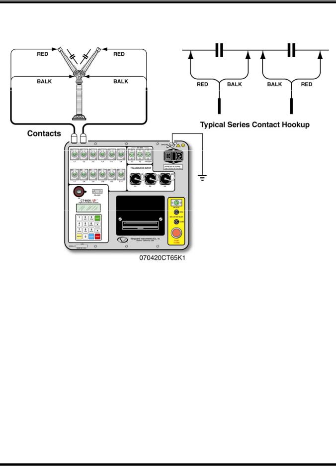
A typical circuit breaker with series contacts is shown in Figure 4.0. In the below example, the circuit breaker has 2 contacts in series per phase. Contact timing channel 1 and 2 are used in the illustration.
NOTE
It is advisable to ground one side of the contacts for most testing purposes. If a breaker is floating or ungrounded, ensure that the contact channel inputs are protected against static discharge.
Figure 3.0 Contact Cable Connection
20
CT-6500 Series 2 Operating Instructions
Figure 4.0 Series Contact Cable Connection
21
CT-6500 Series 2 Operating Instructions
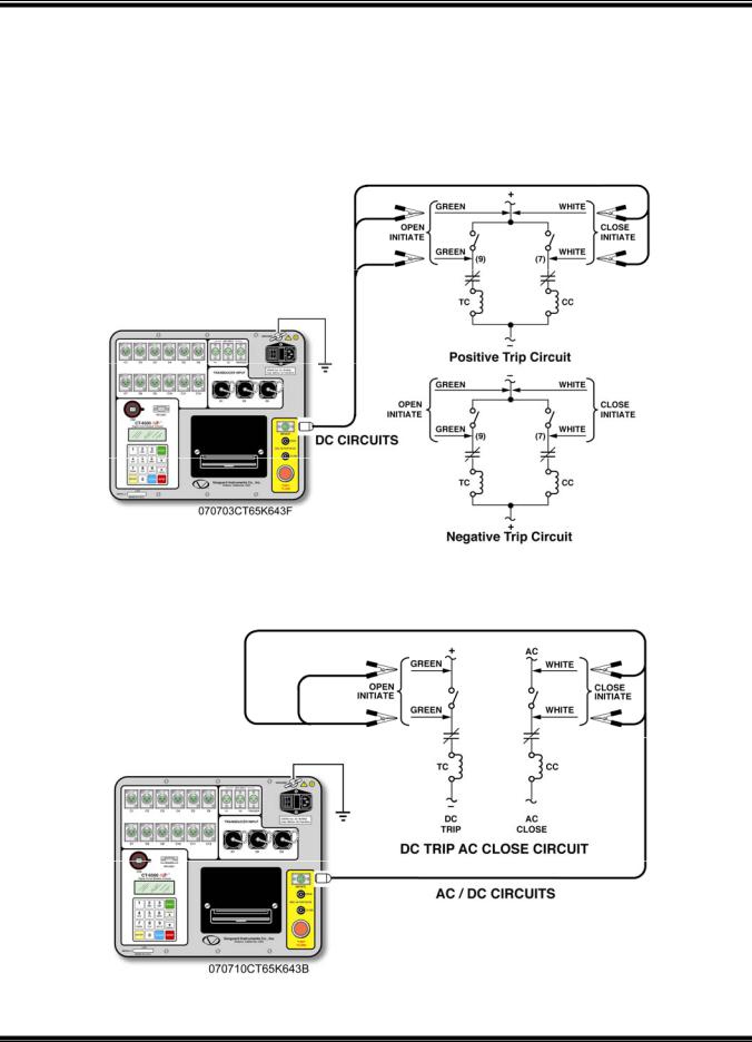
8.2 Initiate Cable Hookup
The CT-6500 will trip or close breakers through a solid-state device, which will operate on any
AC or DC control voltage ranging from 10 to 300 Volts. Both the trip and close circuits are protected by 5 Ampere fuses.
A typical DC trip and DC close, control circuit test hookup is shown in Figure 5.0.
A typical DC trip and AC close, control circuit test hookup is shown in Figure 6.0.
Figure 5.0 DC Trip and DC Close, Initiate Circuit Cable Hook-Up
Figure 6.0 DC Trip and AC Close, Initiate Circuit Cable Hook-Up
22
CT-6500 Series 2 Operating Instructions
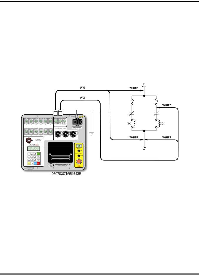
8.3 Analog Voltage Monitor Hookup
The analog voltage input, “V1” permits the user to monitor a breaker's DC control voltage during an operation. The analog voltage input will record the nominal DC voltage at no load and the minimum DC voltage while the Trip or Close coil is energized.
The nominal and minimal voltage readings will be printed on a tabulated report. Analog waveforms will also be plotted in a graphical format. Thus, the user is able to see the breaker's
DC control voltage "dip" under load conditions. Problems, such as a poor connection or an excessive voltage drop, during the circuit breaker operation can be easily detected.
A typical voltage monitoring hook up scheme is shown on Figure 7.0.
NOTE
The maximum voltage that can be recorded is 255 Vdc.
Figure 7.0 Voltage Monitoring Cable Hook-Up
8.4 Digital Voltage Monitor Hookup
The digital, voltage input channel, “V2” permits the user to monitor the voltage status as “ON” or “OFF” states. The voltage “ON” or “OFF” states will be plotted on the graphical report. A typical hook up is shown in Figure 7.0.
23
CT-6500 Series 2 Operating Instructions
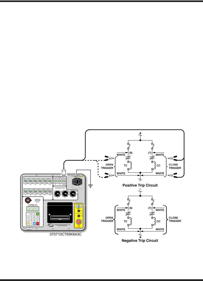
8.5 External Trigger Input
The External Trigger Mode enables the user to start recording data when the CT-6500 senses a voltage. A typical application for the External Trigger Mode is to time a circuit breaker in a close operation and to start timing only when the close coil is energized, thus bypassing the 52X relay delay time.
Since the 52X relay carries the close coil current, the user will need to connect the CT-6500’s initiate cable to the close terminal shown in Figure 5.0. The CT-6500 will energize the 52X relay to start the close operation, which will then start the timing when the CT-6500 senses the voltage across the closing coil. See Figure 8.0 for a typical test hookup. Another application for external trigger is to start timing the breaker when the user trips or closes the breaker remotely.
NOTE
Minimum trigger voltage is set for 30 Vac/dc. Maximum, continuous voltage is limited to 300 Vac/dc. Different trigger voltages can be set at the factory, based upon specific requests.
The CT-6500 will start looking for the external trigger voltage when the message, “AWAITING TRIGGER…” is shown on the LCD screen. The external trigger voltage needs to be sensed by the CT-6500 within 15 seconds after the initiate sequence has begun. The CT-6500 will return to the main menu if no voltage is sensed.
Figure 8.0 External Trigger Cable Hook-Up
24
 Loading...