


TB500ML

Ver. 090816
Model 45700
Safe Operation Practices • Set-Up • Operation • Maintenance • Service • Troubleshooting • Warranty
READ AND FOLLOW ALL SAFETY RULES AND INSTRUCTIONS IN THIS MANUAL
BEFORE ATTEMPTING TO OPERATE THIS MACHINE. FAILURE TO COMPLY WITH THESE
INSTRUCTIONS MAY RESULT IN PERSONAL INJURY.
WARNING
BY MOJACK DISTRIBUTORS, LLC

2
Troy-Bilt TB500ML
Introduction
Patent #: U.S., 8,448,920
Patent #: U.S., 8,387,953
© 2013 (MoJack Distributors, LLC)
MoJack and the MoJack logo are registered trademarks of MoJack Distributors, LLC.
This manual contains assembly, parts, operating,
maintenance, adjustment and safety instructions
for your lift.
BEFORE USING YOUR LIFT, CAREFULLY READ
THIS MANUAL IN ITS ENTIRETY.
By following these operating, maintenance and
safety instructions, you will prolong the life of your
lift and promote safe operation.
If additional information is needed, or should you
require a trained service mechanic, contact your
authorized MoJack equipment dealer or distributor
or call MoJack at 1-877-575-3173.
All MoJack parts are thoroughly tested and inspected
before leaving the factory to ensure that they comply
with all relevant safety standards.
NOTE: Please save this manual for future reference.
NOTE: Location of unit Serial Number.
Submit your questions online at:
www.theMoJack.com
Need Assistance?
Please DO NOT return this product to the store.
Our Customer Service Department is ready to help!
1-877-575-3173

3
Troy-Bilt TB500ML
Warnings and Safety Instructions
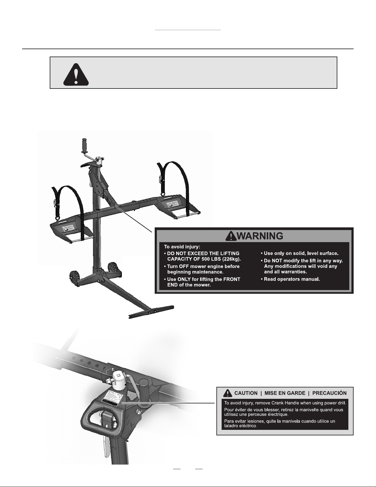
IMPORTANT: The mower lift is intended for use with mowers only. Do not exceed 500 lbs. (226 kg) front end weight.
It should never be used to service other types of machinery unless there is an approved accessory tted for the type of machinery.
Please contact MoJack for approved accessories.
Read and understand all safety and operating instructions before using the mower lift.
Never allow anyone unfamiliar with the safety or operating instructions to use the lift.
Follow all safety and servicing instructions provided by the lawn mower’s manufacturer before using the lift.
Do not modify the lift in any way. Any modications will void any and all warranties and could compromise your personal
safety.
When using the lift, keep ALL bystanders at a safe distance away from the mower lift.
The lift must be used on a solid level surface.
Only lift the FRONT end on the mower.
Do not lift the front end and back end of the mower at the same time.
Only use the lift for mowers that are less than 500lbs (226 kg) front end weight and properly ts in the provided wheel pads
(ie. 10” to 17” diameter and within outside wheel measurements of 31.5” to 62.5”).
Always stop engine and remove key before beginning any work on the mower.
Always place mower in neutral or disengage the hydraulic drive by following the mower owner’s manual.
Never operate the engine while using the mower lift.
Do not exceed the lifting capacity of 500 lbs. (226 kg) front end weight. If you have a question regarding weight of your
machine, please contact the manufacturer at 1-877-575-3173 or a local MoJack Dealer.
If the lift Tower is leaning while lifting or lowering the mower, this indicates an overload condition.
REMOVE THE MOWER IMMEDIATELY.
Towe r must be secured in place with the Tower Clevis Pin before using the lift.
Carrier Locking Handle must be locked into Tower before starting any service on mower.
Do not remove safety warnings or decals from lift.
Before each use, always check for any worn, loose or damaged parts on the lift. If any damaged parts are present, do not
use the lift and contact MoJack.
Do not climb on mower while it is lifted, being lifted or being lowered.
No one should be on the mower while it is lifted, being lifted or being lowered.
After the mower is raised to a working height, always place wheel chocks (not included) behind the back tires of the mower.
Wheel Pads must be equal distance from the Lift Arm to maintain proper balance.
Always secure front mower tires with enclosed safety straps.
Remove all mower attachments before using the lift. Remove all front mower attachments (ballast, bumper or brush guard)
that interferes with handle before using the lift.
Some mowers which are equipped with a fuel tank vent may spill fuel when lifted. If this happens, run fuel level down in
the tank to prevent spilling.
Always use proper personal protection equipment.
Failure to follow these warnings may result in property damage and serious bodily injury or death.
4
Troy-Bilt TB500ML
NOTE: There can be additional safety information contained on parts
and components sourced from suppliers that is not reproduced in this
instruction manual.
CAUTION: Avoid injury!
This symbol and text highlight potential hazards or death to the operator or bystanders
that may occur if the hazards or procedures are ignored.
Warnings and Safety Decals

5
Troy-Bilt TB500ML
LIMITED WARRANTY
For two years for residential use and one year for commercial use MoJack warrants the product against failure due to defect
in material or workmanship when product is used properly. MoJack will replace any defective part at no cost. This warranty
does not cover any product that has been altered or adjusted, or any product that has been misused or abused. THIS IS
THE CUSTOMER’S SOLE AND EXCLUSIVE REMEDY. MOJACK DISCLAIMS ALL IMPLIED WARRANTIES, INCLUDING
THE WARRANTY OF MERCHANTABILITY AND FITNESS FOR A PARTICULAR PURPOSE. MOJACK SHALL NOT BE
LIABLE FOR ANY INCIDENTIAL OR CONSEQUENTIAL DAMAGES. SOME STATES OR PROVINCES DO NOT ALLOW
THE EXCLUSION OR LIMITATION OF THE IMPLIED WARRANTIES OR THE REMEDIES FOR BREACH OF THE
IMPLIED WARRANTIES, SO THESE EXCLUSIONS MAY NOT APPLY TO YOU. THIS LIMITED WARRANTY GIVES YOU
SPECIFIC LEGAL RIGHTS, AND YOU MAY ALSO HAVE OTHER RIGHTS WHICH VARY FROM STATE TO STATE OR
PROVINCE TO PROVINCE.
What does this warranty cover?
This warranty covers against a failure due to a defect in material or workmanship within two years of purchase for
residential use and within one year of purchase for commercial use.
What does this warranty NOT cover?
This warranty does not cover any jack which has been altered or adjusted in any way from its original model. It will not
cover any jack which has been damaged due to misuse, abuse, accident or negligence. This warranty does not cover
incidental or consequential damages.
What is the period of coverage?
Two-year warranty for residential use, one-year for commercial use from date of purchase for the original owner.
What will MoJack do to correct problems?
We will replace any defective part (within the coverage period) at no charge.
How can I get service?
In order to be eligible for service under this warranty you MUST register your jack within thirty (30) days of purchasing.
You must keep your receipt as proof of date of sale. You can register your new jack on our website at www.themojack.com
or by calling our toll-free number 1-877-575-3173.
How do I contact MoJack about a warranty issue?
You can contact us from our website at www.themojack.com or by calling our toll-free number 1-877-575-3173.
Do I have other rights under State Law?
This warranty gives you specic legal rights, and you may also have other rights which vary from state to state.
What is the return policy?
Please refer to the Return Policy and Procedures of your place of purchase for returns and refunds.
Warranty and Returns
6
Troy-Bilt TB500ML
5
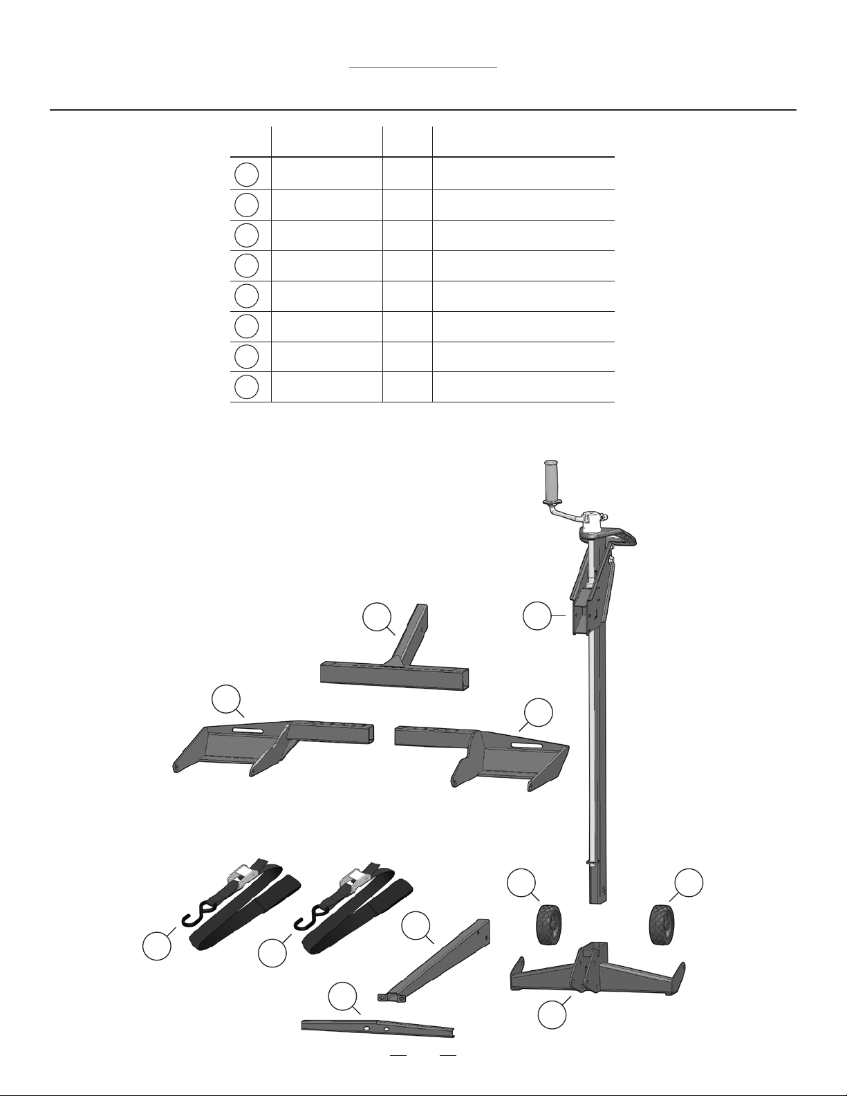
Parts List
5
Par t
No.
Qty.
Description
Tower Assembly
Lift Arm
Base Floor Tube
Base
Base Support Channel
Wheel Pad
Safety Strap
Wheels
509-0014
509-0026
509-0033
509-0048
509-0036
509-0039
009-0007
010-0013
6
7
1
1
1
1
1
2
2
2
Item
No.
1
2
3
4
6
3
8
2
1
6
7
7
4
8
8
7
Troy-Bilt TB500ML
9
Wheel Pad Support Rod
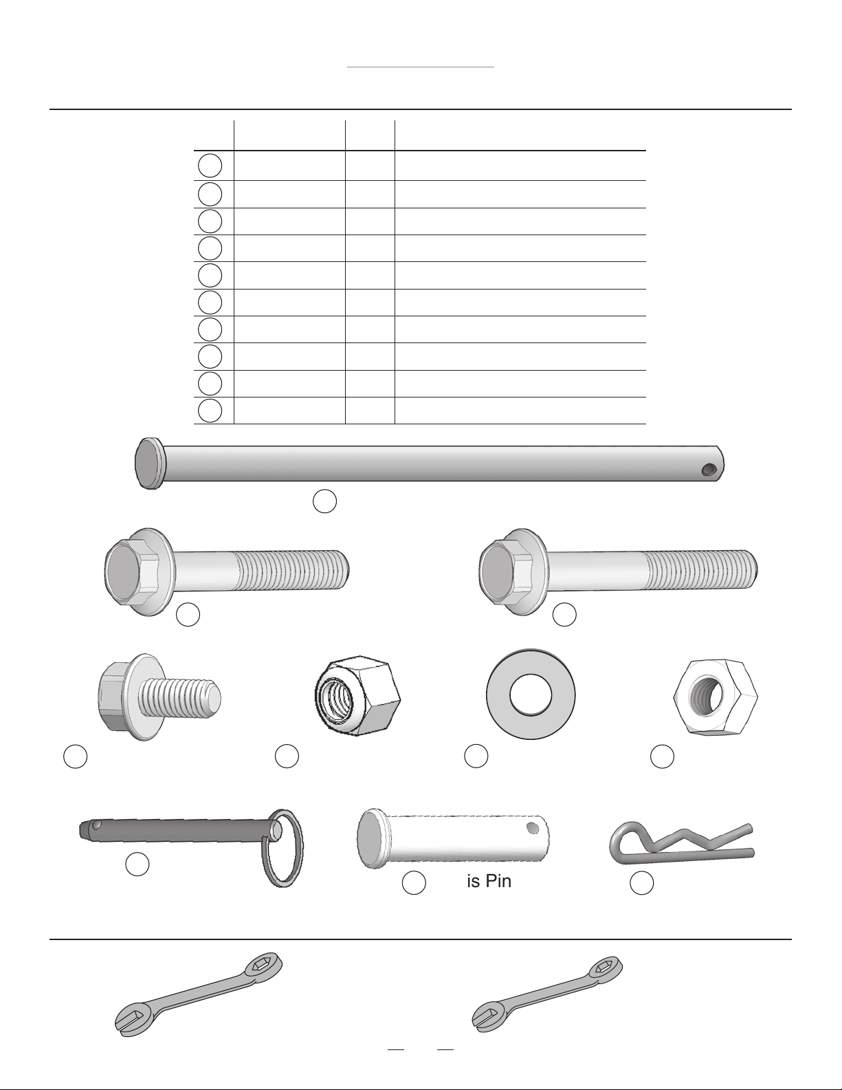
Hardware List
Tools Needed for Assembly (not included)
17mm Wrench (2 each)
13
Par t
No.
Qty.
Description
16
2
2
2
2
4
4
2
2
2
4
Item
No.
9
10
11
12
17
Clevis Pin
16
Push Pin
12
Flange Head Bolt
M8-1.25 X 16
13
Nylon Lock Nut
M10-1.5
10
Flange Head Bolt
M10-1.5 X 60
18
Hair Pin
14
Washer M10
14
15
Nut M10
11
Flange Head Bolt
M10-1.5 X 65
18
15
Wheel Pad Support Rod
Flange Head Bolt M10-1.5 X 60
Flange Head Bolt M10-1.5 X 65
Flange Head Bolt M8-1.25 X 16
Nylon Lock Nut – M10-1.5
Washer – M10
Nut – M10
Push Pin
Clevis Pin
Hair Pin
509-0040
003-0005
003-0016
003-0007
002-0001
001-0014
002-0008
001-0013
001-0012
001-0010
17
12mm Wrench (1 each)
8
Troy-Bilt TB500ML
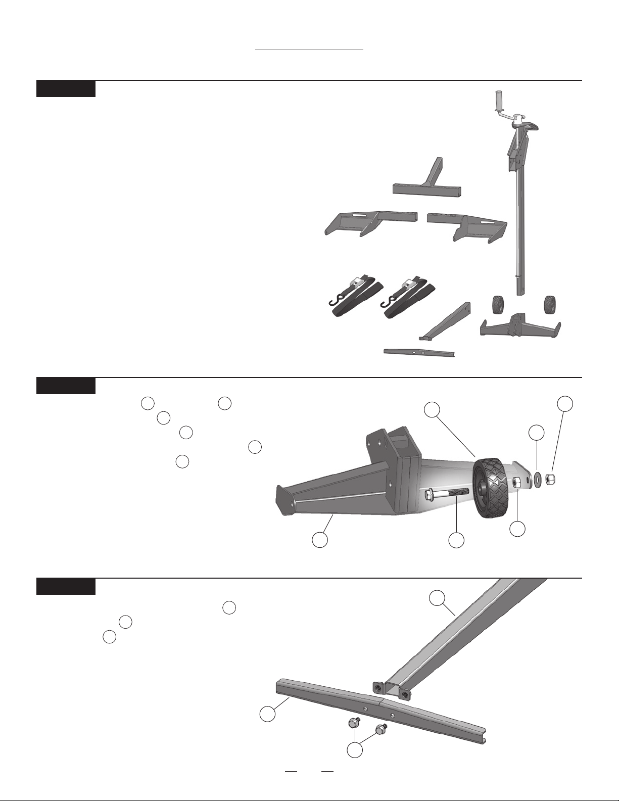
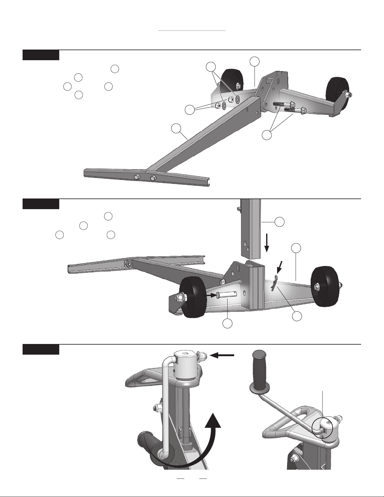
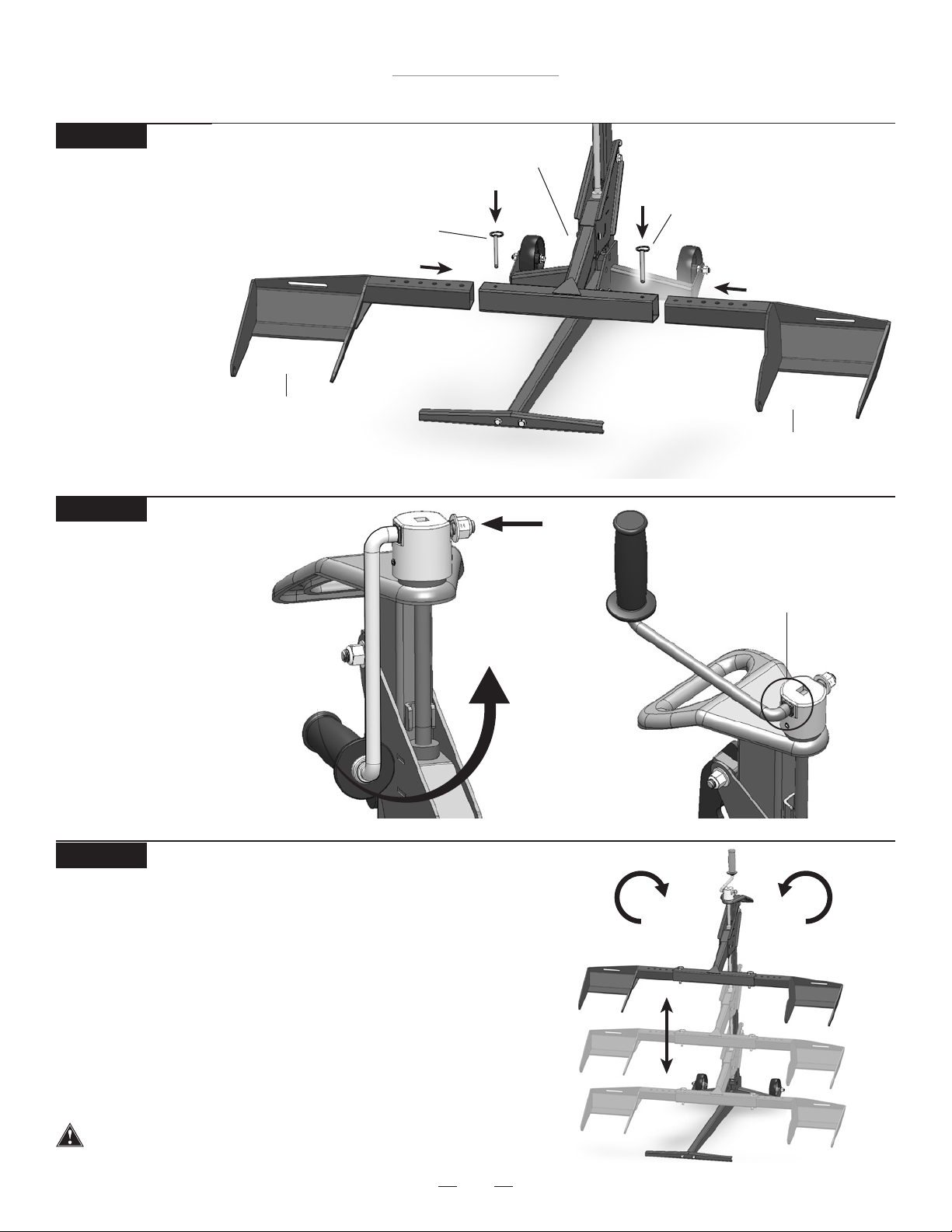
Assemble the Base Support Channel to the
Base Floor Tube by inserting the two
Flange Bolts and tighten with 12mm wrench.
Assembly Instructions
STEP 1
Remove lift from package.
Inventory items to be certain all parts and hardware
are present. If any parts or hardware are missing,
please contact MoJack at 1-877-575-3173 or
email us at parts@themojack.com.
Base Support Channel
5
Base Floor Tube
3
Flange Bolts
12
STEP 3
5
3
12
STEP 2
Assemble the Wheel to the Base
by inserting Flange Bolt through the
wheel and threading the Nut . Insert
Flange Bolt through the Base, add Washer
and secure with Nylock Nut .
Repeat with second Wheel.
Note: Do not over tighten Nylon Lock Nut.
Base
4
Wheel
8
Flange Bolt
11
Washer
14
Nut
15
Nylock Nut
13
8 4
11
15
14
13
9
Troy-Bilt TB500ML
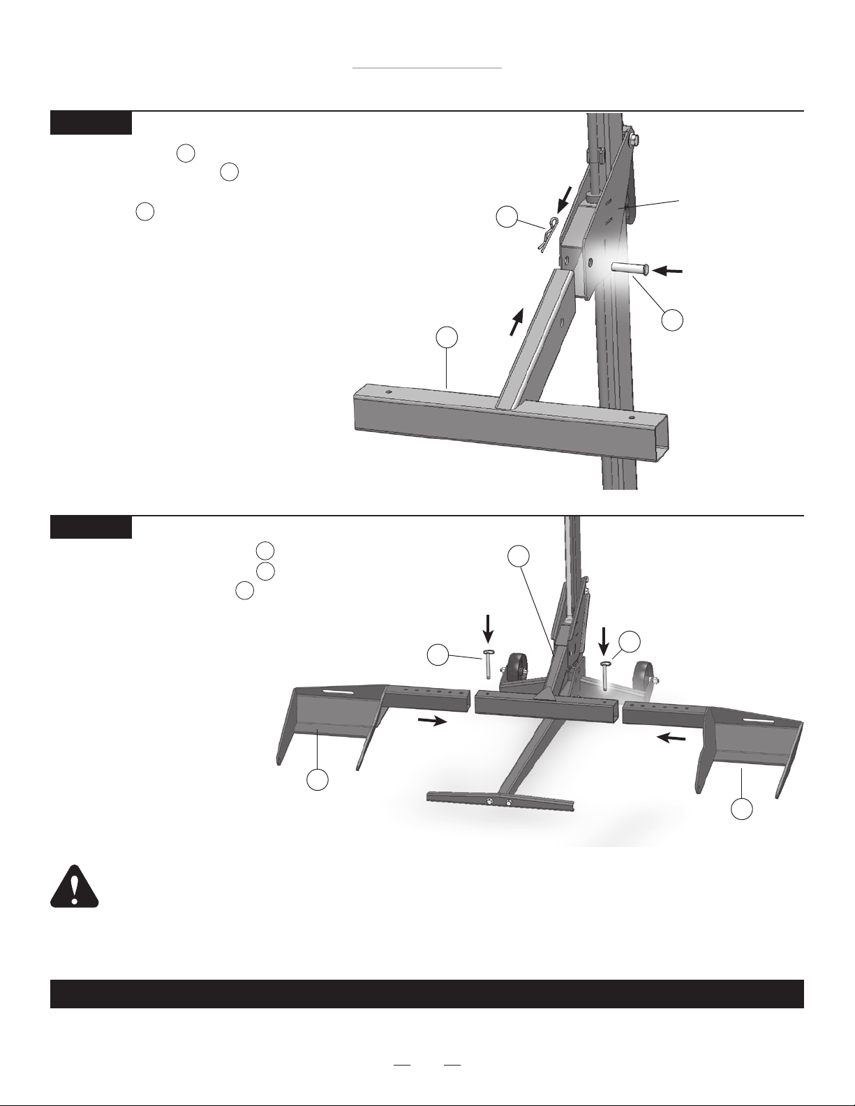
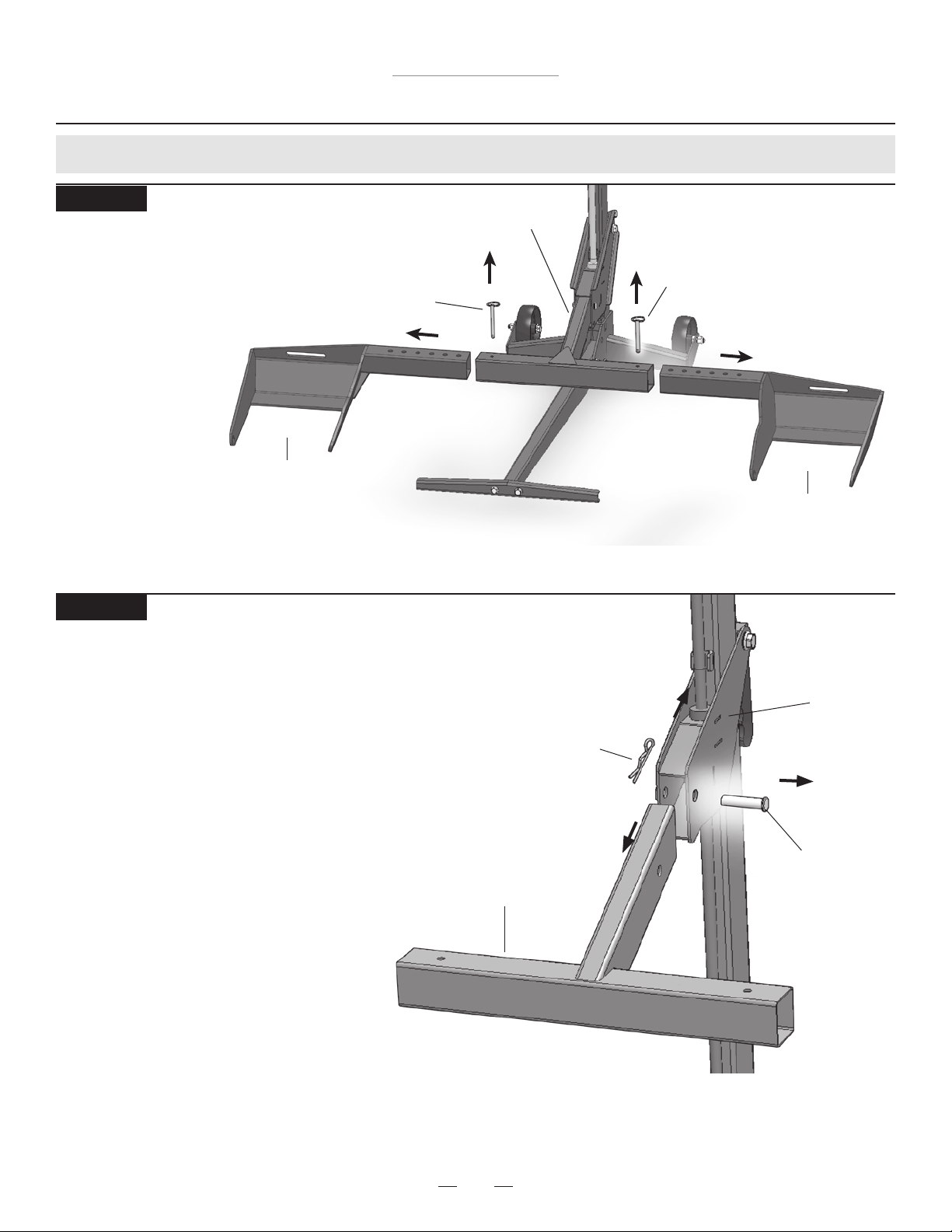
Assemble Base with Wheels to the
Base Floor Tube by inserting the two
Flange Bolts , Washers and
Nylon Lock Nuts and tighten with
15mm wrenches.
Assembly Instructions
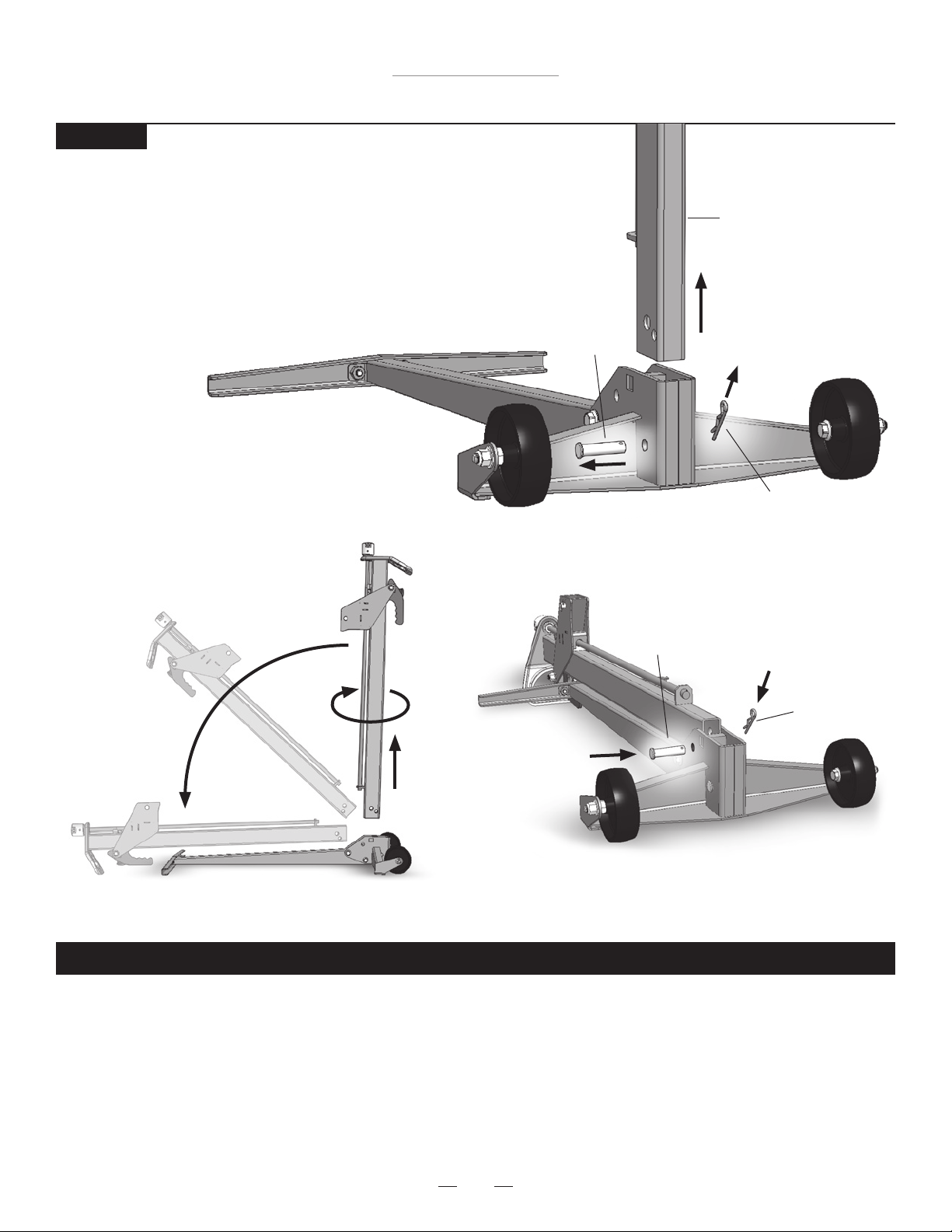
STEP 5
Insert the Tower Assembly to the
Base with Wheels and affix with
Clevis Pin and Hair Pin as shown.
1
4
17 18
Towe r
1
Clevis Pin
17
Hair Pin
18
Base with Wheels
4
Locked Position
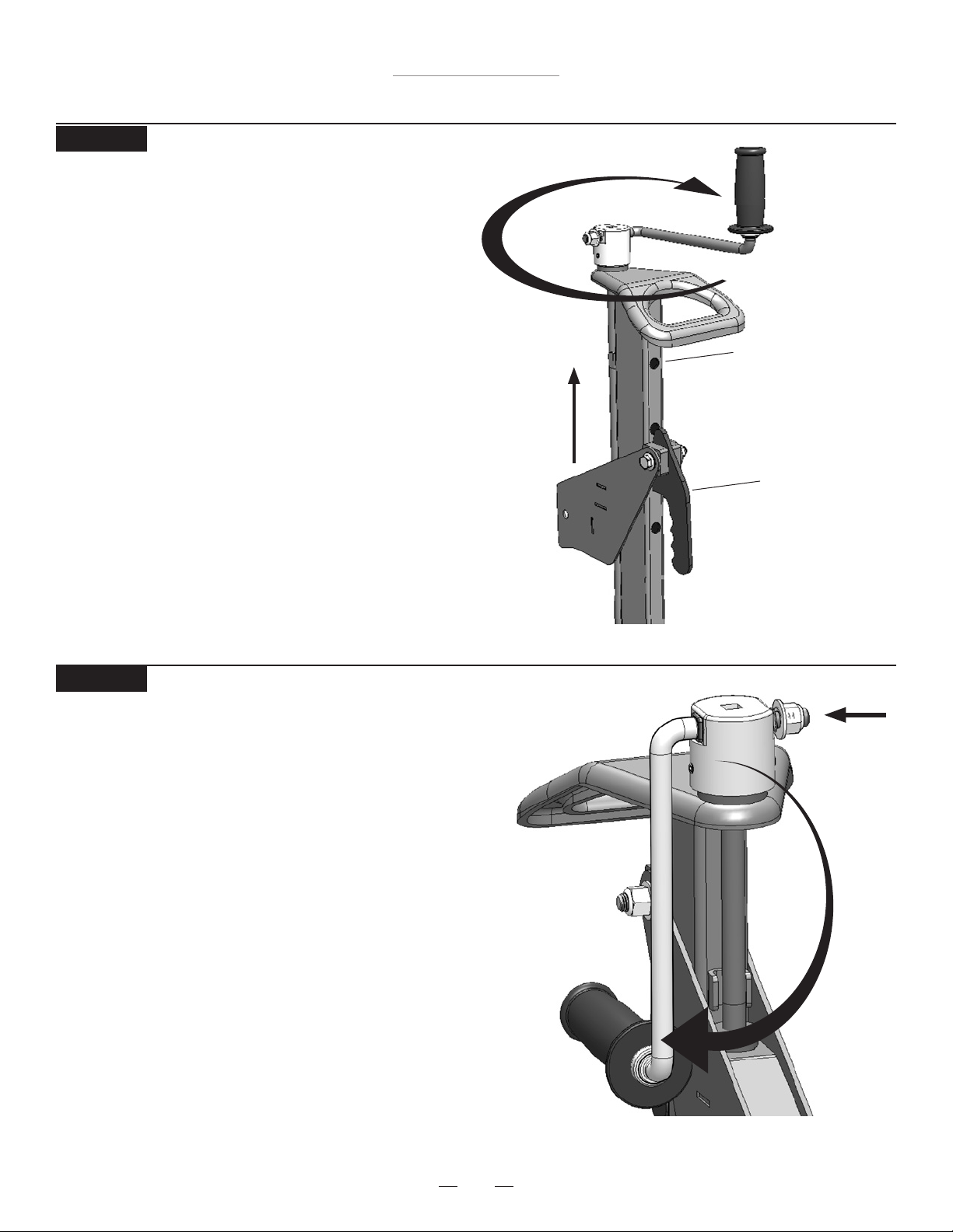
STEP 6
Push in side of handle and
rotate from storage position
to the operating position.
Allow to seat into the locked
position.
STEP 4
4
10
3
14
Nylon Lock Nuts
13
Base Floor Tube
3
Flange Bolts
10
Base with Wheels
4
Washer
14
13
10
Troy-Bilt TB500ML
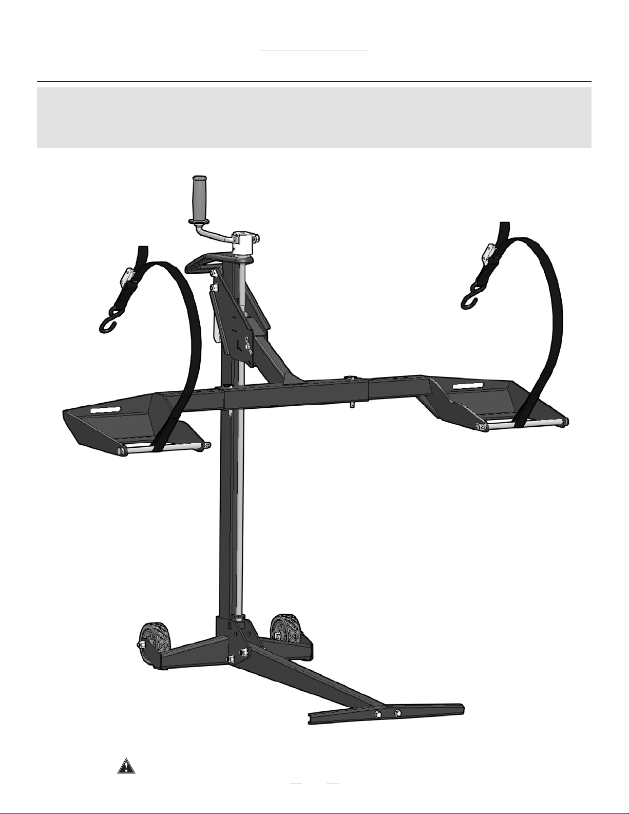
THIS COMPLETES ASSEMBLY.
STEP 7
Insert the Lift Arm into the Carrier
and insert the Clevis Pin through
the hole in Carrier and lock by fastening
the Hair Pin to the Clevis Pin.
2
17
18
Hair Pin
18
Lift Arm
2
Carrier
Clevis Pin
17
Assembly Instructions
Push Pin
16
Lift Arm
2
Wheel Pad Lift Arm
6
STEP 8
Slide the Wheel Pad Lift Arms
onto both sides of the Lift Arm
and secure with Push Pins .
NOTE: The Wheel Pads can be
moved in or out to t different mower
widths. Use the conguration that
works best with your model of
lawn mower.
NOTE: The Safety Straps must
be used during operation
(see Step 9 of the Operating
Instructions).
6
2
16
Push Pin
16
WARNING: Wheel pads must be equal distance from the Lift Arm to maintain proper balance.
For additional information, see see Step 6 of the Operating Instructions.
Wheel Pad Lift Arm
6
11
Troy-Bilt TB500ML
Operating Instructions
Before using the mower lift, carefully read this manual in its entirety.
Some steps of the Operating Instructions are repeated from the
Assembly Instructions. The Operating Instructions will show a full
working cycle of the mower lift.
12
Troy-Bilt TB500ML
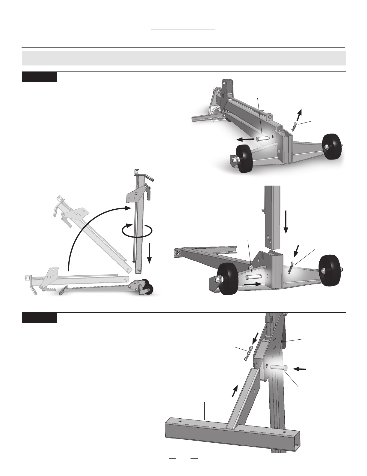
Clevis Pin
Hair Pin
Operating Instructions
Preparing for use (Steps 1 - 7)
STEP 1
STEP 2
Hair Pin
Lift Arm
Carrier
Clevis Pin
Installing Lift Arm
• Insert the Lift Arm into the Carrier and insert
the Clevis Pin through the hole in Carrier and
lock by fastening the Hair Pin to the Clevis Pin.
Clevis Pin
Hair Pin
Towe r
Unfolding the Mower Lift (if not applicable, skip to Step 2)
• Remove Hair Pin and Clevis Pin from the Wheel Frame.
• Remove the Tower out of the Wheel Frame.
• Rotate Tower 180 degrees and insert into Wheel Frame.
• Secure the Tower to the Wheel Frame by inserting
Clevis Pin and Hair Pin.
13
Troy-Bilt TB500ML
Push Pin
Push Pin
Lift Arm
Wheel Pad Lift Arm
Operating Instructions
STEP 3
Installing Wheel Pad Lift Arms
• Slide Wheel Pad Lift Arms
into both sides of the
Lift Arm and secure
with Push Pins.
STEP 4
Preparing the handle
• Push in side of handle
and rotate from storage
position to the operating
position. Allow to seat
into the locked position.
Wheel Pad Lift Arm
Locked Position
STEP 5
Familiarize yourself with the jack
• Practice raising and lowering the Lift Arm before attempting to
lift the mower (see Steps 10 – 13 on how to raise and lower
the Lift Arm).
• Practice Step 15 if you intend to raise or lower the
mower with a drill attachment.
NOTE: Remove all front mower attachments that interfere with
handle before using the lift.
When using the lift, keep ALL bystanders at a safe
distance away from the mower lift.
RAISE LOWER
14
Troy-Bilt TB500ML
Operating Instructions
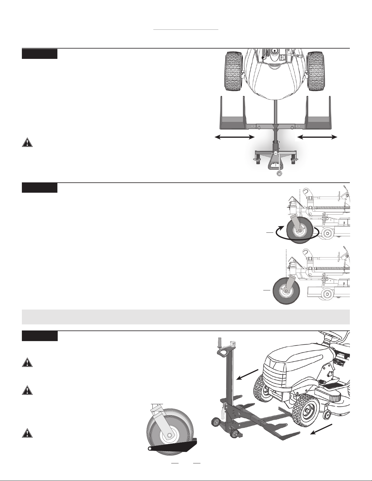
STEP 6
Aligning Wheel Pads to Fit Mower
• Position the jack in front of the mower.
• Remove Push Pins and adjust the wheel pad to align with
the mower’s front tires.
• Replace the Push Pins to lock the Wheel Pad Lift Arms to
the Lift Arm.
Wheel Pad Lift Arms must be equal distance from the
Lift Arm to maintain proper balance.
Using the Lift (Steps 8 - 15)
STEP 8
Move mower onto jack
The jack must be used on a solid level surface.
• Drive or roll the mower onto the Wheel Pads.
Stop engine and remove the key.
NOTE: Wheel Pads accommodate wheel
sizes from 10” – 17” (25cm – 43cm).
Not for use with tires
over 17” (43cm) in size.
STEP 7
(optional – if not applicable, skip to Step 8)
In some cases, the mower deck or anti-scalping wheels will hit the
Lift Arm while the mower is being raised. This is often the case if
part of the deck (including the anti-scalping wheels) protrudes past
the center line of the front wheels of the mower. If this happens:
• Rotate the front tires 180° so that they are in the reverse position.
• Slide the lift as close to the wheels as possible.
NOTE: Reference Step 6 for Aligning Wheel Pads to t
ZTR mower.
Reverse
Wheel
Position
Forward
Wheel
Position
15
Troy-Bilt TB500ML
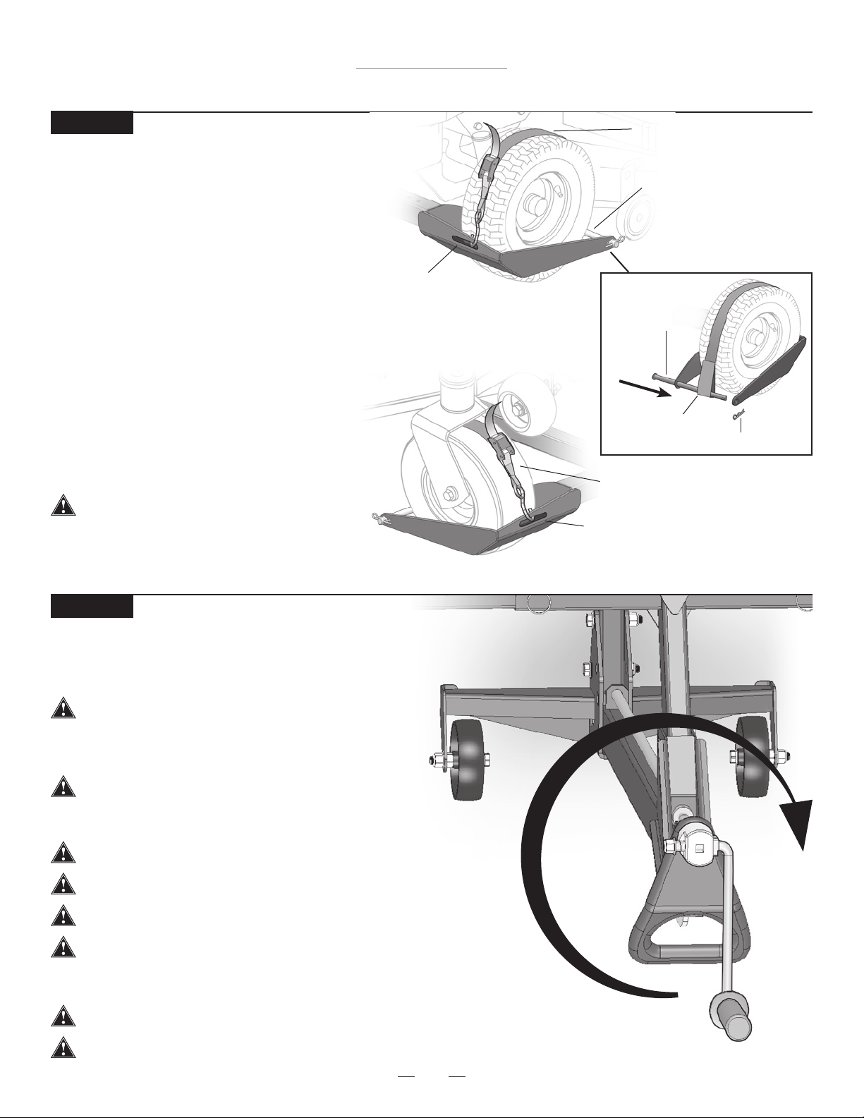
Wheel Pad
Slot
Safety Strap
Wheel
Support
Rod
Safety
Strap
STEP 9
Operating Instructions
STEP 10
Raising the Mower
• Raise the mower by rotating the Crank Handle clockwise.
• See Step 15 for raising the mower with drill attachment.
If the lift Tower is leaning while lifting or lowering
the mower, this indicates an overload condition.
REMOVE THE MOWER IMMEDIATELY.
The jack must be used on a solid level surface.
The engine must be turned off and key removed.
The mower must be in neutral when raising or
lowering to allow the wheels roll as the mower is
raised or lowered.
The parking brake must be off during this step.
Always use attached safety straps. The Safety Straps must be rmly tightened.
Do not exceed the lifting capacity of 500 lbs.
(226 kg) front end weight. If you have a question
regarding weight of your machine, please contact
MoJack at 1-877-575-3173.
Mower deck must be raised to highest setting.
Strapping Front Mower Tires to Wheel Pads
• Secure the front mower tires to the Wheel
Pads using the Safety Straps. Secure the
hook on the Safety Strap to the Wheel Pad
Slot. The Safety Strap hook should always be
facing upward.
• Extend the Safety Strap over the top of tire.
• Insert the Wheel Support Rod through one
hole on the Wheel Pad, through the loop on
the Safety Strap and through the other side of
the Wheel Pad. Secure with Large Hair Pin.
• Squeeze the metal buckle and pull end of
strap to tighten the Safety Straps over the top
of the tires to secure mower to Wheel Pads.
NOTE: Inspect Safety Strap for wear before
each use.
Always secure front mower tires with
enclosed safety straps.
Wheel Pad
Slot
Wheel
Support Rod
Safety Strap
Loop
Hair Pin
16
Troy-Bilt TB500ML
STEP 13
Operating Instructions
Lowering the Mower
• Remove wheel chocks.
• Release the parking brake.
• Mower must be in neutral or hydraulic drive disengaged.
• Pull and hold the Carrier Locking Handle out and turn
the Crank Handle counter clockwise until Wheel Pads
are rmly on the ground. The Carrier Locking Handle
must be pulled out until it clears the bottom Tower
Hole. It may be necessary to raise the Carrier
slightly to allow the Carrier Locking Handle to be
pulled out.
NOTE: The lift is equipped with a clutch to protect itself
from accidental damage. If the Carrier Locking Handle is
not disengaged when lowering, the clutch will release the
Crank Handle from the screw and rotate freely.
To re-engage the Crank Handle, turn clockwise for
a few turns.
STEP 12
Preparing the Mower for Service
• Place wheel chocks (not included) behind the back tires of the
mower.
• Apply the parking brake on the mower.
• The Carrier Locking Handle must be locked into one of the
two Tower Holes.
Wheel Chock
Tower Holes
Carrier
Locking
Handle
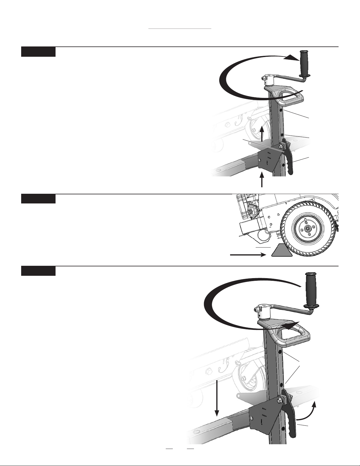
STEP 11
Raising Lift Arm to Locking Position
• Raise the Lift Arm until the Carrier Locking Handle drops into one
of the three Tower Holes. The Tower Locking Holes are the
automaticsafety engagement system.
• The Carrier Locking Handle automatically drops into the Tower
Holes as the Carrier passes the Tower Holes when raising.
Locking engagement occurs at 14”, 19” and 24”.
NOTE: When lowering the Lift Arm, the Carrier Locking Handle must
be held out by the operator until it clears the bottom Tower Hole.
NOTE: The lift is equipped with a clutch to protect itself from
accidental damage. If the Carrier Locking Handle is not disengaged
when lowering, the clutch will release the Crank Handle from the
screw and rotate freely. To re-engage the Crank Handle,
turn clockwise for a few turns.
Carrier
Locking
Handle
19” – Second
Locking Hole
height
Tower Locking
Holes are the
automatic
safety
engagement
system
24” – Third
Locking Hole
height
14” – First
Locking Hole
height
17
Troy-Bilt TB500ML
Square Driver not included
Nylock
Locking
Nut
Spring
Crank
Handle
Before using a drill,
remove the Crank
Handle
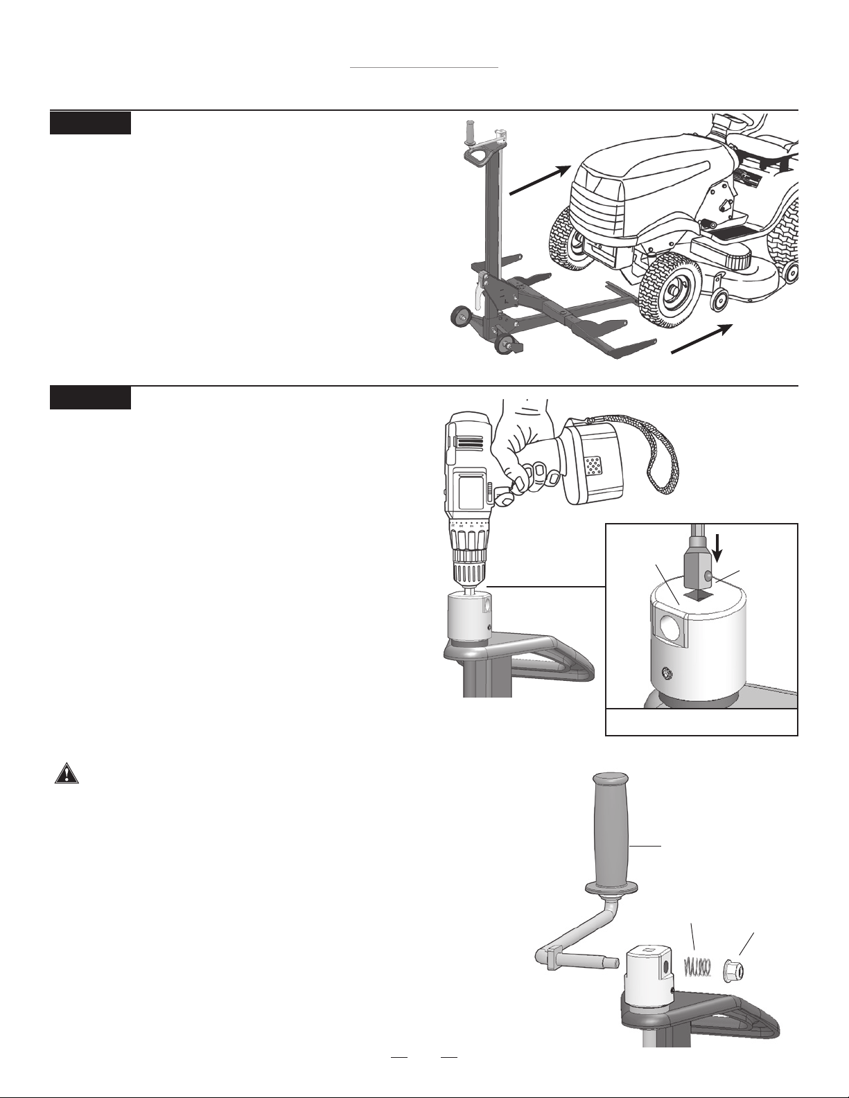
Raising the lift with a power drill
(optional – power drill not included)
The lift can be raised or lowered by using a variable
speed corded drill (7 amp minimum) or variable speed
cordless drill (18V minimum). The drill will require a
3/8” square driver (not included).
• Remove Crank Handle by taking off the Nylon Lock
Nut and Spring using 15mm wrench.
After Crank Handle removal, re-attach Spring and
Nylon Lock Nut to Crank Handle to prevent loss.
• Firmly insert the 3/8” square driver in the Square
Receiver. Rotate the drill forward (clockwise) to
raise the Lift Arm and rotate the drill in reverse
(counterclockwise) to lower the Lift Arm.
• Carrier Locking Handle must be manually pulled out when lowering
until it clears the bottom Tower Hole.
NOTE: Crank Handle must be removed in order to use the drill attachment.
Follow all other operating instructions while using the drill
attachment. Replace the Crank Handle as necessary for future use.
NOTE: When re-assembling handle, take care not to over-tighten
the Nylon Lock Nut against the spring. There should be enough
free space for the handle to be pushed in to move from storage
position to operating position.
NOTE: When re-assembling the handle, a “popping” sound may
occur due to the re-engagement of the clutch system.
Operating Instructions
STEP 15
Operator must have a rm grip on the drill before raising or
lowering the Lift Arm.
3/8”
Square
Driver
Square
Receiver
STEP 14
Removing the Mower from the lift
• Remove the Safety Straps from front mower tires.
• Drive or roll the mower off of the Wheel Pads.
Make sure drill is
fully charged and
set at highest
torque.
18
Troy-Bilt TB500ML
Hair Pin
Lift Arm
Carrier
Clevis Pin
Operating Instructions
STEP 17
Removing the Lift Arm
• While holding the Lift Arm, remove the
Hair Pin and Clevis Pin from Lift Arm.
• Slide the Lift Arm out of the Carrier.
• Store the Hair Pin and Clevis Pin in the
Lift Arm to prevent loss.
Preparing for Storage (Steps 16 - 20)
Push Pin
Push Pin
Lift Arm
Wheel Pad Lift Arm
Wheel Pad Lift Arm
STEP 16
Removing the Wheel Pads
• Remove Push Pins and
pull the Wheel Pad
Lift Arms out of the
Lift Arm.
• Store the Push Pins
in the Lift Arm to
prevent loss.
19
Troy-Bilt TB500ML
Operating Instructions
STEP 19
Rotate Crank Handle to Storage position
• Push in side of handle and rotate from operating
position to the storage position. Allow to seat into
the locked position.
STEP 18
Raise Carrier
• Raise the Carrier by turning the Crank Handle
clockwise until the Carrier Locking Handle
drops into the top Tower Hole.
Top Tower Hole
Carrier
Locking
Handle
20
Troy-Bilt TB500ML
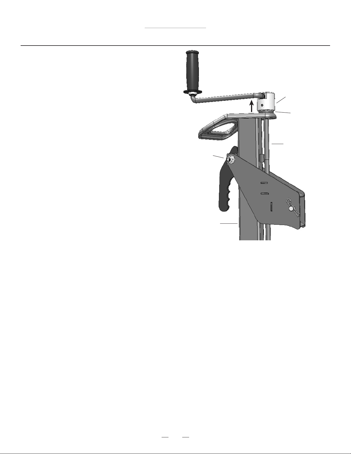
STEP 20
THE LIFT IS NOW READY FOR STORAGE OR TRANSPORT.
Clevis Pin
Hair Pin
Moving the Tower Assembly to Storage position
• Remove Hair Pin and Clevis Pin from bottom of Tower Assembly.
• Raise the Tower out of the Base by pulling up on the Lift Handle.
• Rotate Tower Assembly 180 degrees and lower into storage position.
• Secure the Tower by inserting Clevis Pin and Hair Pin to lock
Tower Assembly in storage position.
Tower Assembly
Clevis Pin
Hair Pin
Operating Instructions
21
Troy-Bilt TB500ML
Maintenance Schedule
• Before each use, always check for any worn, loose or
damaged parts on the lift. If any damaged parts are
present, do not use the lift and contact MoJack at
1-877-575-3173.
• Clean and oil the entire screw thread after every fty
(50) uses or at least once a year using light machine
oil.
• Place lithium grease between the Crank Handle Base
and the brass bearing after every fty (50) uses or once
a year. Without weight on carrier, lift the Crank Handle
to create a small gap between the brass bearing and
the Crank Handle Base. Use a small brush to apply the
lithium grease between the two surfaces.
• Spray grease or lube in Carrier Locking Handle pivot
after every fty (50) uses or at least once a year.
• Wipe clean and lightly apply grease to front and back
of Tower Assembly after every fty (50) uses or at least
once a year.
Screw Thread
Brass Bearing
Crank Handle
Base
Carrier
Locking
Handle
pivot
Towe r
Assembly
 Loading...