


Operator’s Manual
Electric Start Capable
4-Cycle Gas Trimmer
TB525 EC
TABLE OF CONTENTS
Service Information . . . . . . . . . . . . . . . . . . . . . . . . . . . . . . . . . . . . . . . . . . . .1 Rules for Safe Operation . . . . . . . . . . . . . . . . . . . . . . . . . . . . . . . . . . . . . . .2 Know Your Unit . . . . . . . . . . . . . . . . . . . . . . . . . . . . . . . . . . . . . . . . . . . . . . .4 Assembly Instructions . . . . . . . . . . . . . . . . . . . . . . . . . . . . . . . . . . . . . . . . .4 Oil and Fuel Information . . . . . . . . . . . . . . . . . . . . . . . . . . . . . . . . . . . . . . . .5 Starting and Stopping Instructions . . . . . . . . . . . . . . . . . . . . . . . . . . . . . . . .6 Operating Instructions . . . . . . . . . . . . . . . . . . . . . . . . . . . . . . . . . . . . . . . . .7 Maintenance and Repair Instructions . . . . . . . . . . . . . . . . . . . . . . . . . . . . . .8 Cleaning and Storage . . . . . . . . . . . . . . . . . . . . . . . . . . . . . . . . . . . . . . . . .10 Optional Accessory . . . . . . . . . . . . . . . . . . . . . . . . . . . . . . . . . . . . . . . . . .10 Troubleshooting Chart . . . . . . . . . . . . . . . . . . . . . . . . . . . . . . . . . . . . . . . .10 Specifications . . . . . . . . . . . . . . . . . . . . . . . . . . . . . . . . . . . . . . . . . . . . . . .10 Warranty Information . . . . . . . . . . . . . . . . . . . . . . . . . . . . . . . . . . . . . . . . .24
SAVE THESE INSTRUCTIONS
SERVICE INFORMATION
DO NOT RETURN THIS UNIT TO THE RETAILER. PROOF OF PURCHASE WILL BE REQUIRED FOR WARRANTY SERVICE.
For assistance regarding the assembly, controls, operation or maintenance of the unit, please call the Customer Support Department at 1-800-828-5500 in the United States or 1-800-668-1238 in Canada. Additional information about the unit can be found on our website at www.troybilt.com or www.troybilt.ca.
For service, please call the Customer Support Department to obtain a list of authorized service dealers near you. Service on this unit, both within and after the warranty period, should only be performed by an authorized and approved service dealer. When servicing, use only identical replacement parts.
All information, illustrations, and specifications in this manual are based on the latest product information available at the time of printing. We reserve the right to make changes at any time without notice.
Copyright© 2011 MTD SOUTHWEST INC, All Rights Reserved.
769-07280 P00 |
10/11 |

RULES FOR SAFE OPERATION
SPARK ARRESTOR NOTE
NOTE: For users on U.S. Forest Land and in the states of California, Maine, Oregon and Washington. All U.S. Forest Land and the state of California (Public Resources Codes 4442 and 4443), Oregon and Washington require, by law that certain internal combustion engines operated on forest brush and/or grass-covered areas be equipped with a spark arrestor, maintained in effective working order, or the engine be constructed, equipped and maintained for the prevention of fire. Check with your state or local authorities for regulations pertaining to these requirements. Failure to follow these requirements could subject you to liability or a fine. This unit is factory equipped with a spark arrestor. If it requires replacement, ask your LOCAL SERVICE DEALER to install the Accessory Part #753-05245 Muffler
Read the Operator’s Manual and follow all warnings and safety instructions. Failure to do so can result in serious injury to the operator and/or bystanders. FOR QUESTIONS, CALL 1-800-828-5500 IN U.S. OR 1-800-668-1238 in CANADA
The purpose of safety symbols is to attract your attention to possible dangers. The safety symbols, and their explanations, deserve your careful attention and understanding. The safety warnings do not by themselves eliminate any danger. The instructions or warnings they give are not substitutes for proper accident prevention measures.
SYMBOL MEANING
SAFETY ALERT: Indicates danger, warning or caution. Attention is required in order to avoid serious personal injury. May be used in conjunction with other symbols or pictographs.
DANGER: Failure to obey a safety warning will result in serious injury to yourself or to others. Always follow the safety precautions to reduce the risk of fire, electric shock and personal injury.
WARNING: Failure to obey a safety warning can result in injury to yourself and others. Always follow the safety precautions to reduce the risk of fire, electric shock and personal injury.
CAUTION: Failure to obey a safety warning may result in property damage or personal injury to yourself or to others. Always follow the safety precautions to reduce the risk of fire, electric shock and personal injury.
NOTE: Advises you of information or instructions vital to the operation or maintenance of the equipment.
• IMPORTANT SAFETY INSTRUCTIONS •
CALIFORNIA PROPOSITION 65
WARNING: Engine exhaust, some of its constituents and certain finished components contain or emit chemicals known to the State of California to cause cancer and birth defects or other reproductive harm. Wash hands after handling.
READ ALL INSTRUCTIONS BEFORE OPERATING
WARNING: When using the unit, you must follow the safety rules. Please read these instructions before operating the unit in order to ensure the safety of the operator and any bystanders. Please keep these instructions for later use.
SAFETY WARNINGS FOR GAS UNITS
WARNING: Gasoline is highly flammable, and its vapors can explode if ignited. Take the following precautions:
•Store fuel only in containers specifically designed and approved for the storage of such materials.
•Always stop the engine and allow it to cool before filling the fuel tank. Never remove the fuel tank cap or add fuel when the engine is hot. Always loosen the fuel tank cap slowly to relieve any pressure in the tank before fueling. Do not smoke.
•Always add fuel in a clean, well-ventilated outdoor area where there are no sparks or flames. Do not smoke.
•Read the instructions carefully. Be familiar with the controls and proper use of the unit.
•Do not operate this unit when tired, ill, or under the influence of alcohol, drugs, or medication.
•Children and teens under the age of 15 must not use the unit, except for teens guided by an adult.
•All guards and safety attachments must be installed properly before operating the unit.
•Inspect the unit before use. Replace damaged parts. Check for fuel leaks. Make sure all fasteners are in place and secure. Replace parts that are cracked, chipped, or damaged in any way. Do not operate the unit with loose or damaged parts.
•Carefully inspect the area before starting the unit. Remove all debris and hard or sharp objects such as glass, wire, etc.
•Be aware of the risk of injury to the head, hands and feet.
•Clear the area of children, bystanders, and pets. At a minimum, keep all children, bystanders, and pets outside a 50 feet (15 m) radius; there still may be a risk to bystanders from thrown objects. Bystanders should be encouraged to wear eye protection. If you are approached, stop the unit immediately.
•Use only 0.095 inch, 2.41 mm diameter original equipment manufacturer replacement line. Never use metal-reinforced line, wire or rope. These can break off and become dangerous projectiles.
•Squeeze the throttle control and check that it returns automatically to the idle position. Make all adjustments or repairs before using unit.
•Never operate the unit without the fuel cap securely in place.
•Avoid creating a source of ignition for spilled fuel. Wipe up any spilled fuel from the unit immediately, before starting the engine. Move the unit at least 30 feet (9.1 m) from the fueling source and site before starting the engine. Do not smoke.
•Never start or run the unit inside a closed room or building. Breathing exhaust fumes can kill. Only operate this unit in a well-ventilated outdoor area.
WHILE OPERATING
•Wear safety glasses or goggles that meet ANSI Z87.-1989 standards and are marked as such. Wear ear/hearing protection when operating this unit. Wear a face or dust mask if the operation is dusty.
•Wear heavy long pants, boots, gloves and a long sleeve shirt. Do not wear loose clothing, jewelry, short pants, sandals or go barefoot. Secure hair above shoulder level.
•The cutting attachment shield must always be in place while operating the unit as a trimmer. Do not operate unit without both trimming lines extended, and the proper line installed. Do not extend the trimming line beyond the length of the shield.
•This unit has a clutch. The cutting attachment remains stationary when the engine is idling. If it does not, have the unit adjusted by an authorized service technician.
•Adjust the handle to your size in order to provide the best grip.
•Be sure the cutting attachment is not in contact with anything before starting the unit.
•Use the unit only in daylight or good artificial light.
•Avoid accidental starting. Be in the starting position whenever pulling the starter rope. The operator and unit must be in a stable position while starting. Refer to Starting and Stopping Instructions.
•Use the right tool. Only use this tool for its intended purpose.
•Do not overreach. Always keep proper footing and balance.
2
RULES FOR SAFE OPERATION
•Always hold the unit with both hands when operating. Keep a firm grip on both handles or grips.
•Keep hands, face, and feet at a distance from all moving parts. Do not touch or try to stop the cutting attachment when it rotates.
•Do not touch the engine, gear housing or muffler. These parts get extremely hot from operation, even after the unit is turned off.
•Do not operate the engine faster than the speed needed to cut, trim or edge. Do not run the engine at high speed when not cutting.
•Always stop the engine when cutting is delayed or when walking from one cutting location to another.
•If you strike or become entangled with a foreign object, stop the engine immediately and check for damage. Do not operate before repairing damage. Do not operate the unit with loose or damaged parts.
•Stop the unit, switch the engine to off, and disconnect the spark plug for maintenance or repair.
•Use only original equipment manufacturer replacement parts and accessories for this unit. These are available from your authorized service dealer. Use of any unauthorized parts or accessories could lead to serious injury to the user, or damage to the unit, and void your warranty.
•Keep unit clean of vegetation and other materials. They may become lodged between the cutting attachment and shield.
•To reduce fire hazard, replace a faulty muffler and spark arrestor. Keep the engine and muffler free from grass, leaves, excessive grease or carbon build up.
OTHER SAFETY WARNINGS
•Never store a fueled unit inside a building where fumes may reach an open flame or spark.
•Allow the engine to cool before storing or transporting. Be sure to secure the unit while transporting.
•Store the unit in a dry area, locked up or up high to prevent unauthorized use or damage, out of the reach of children.
•Never douse or squirt the unit with water or any other liquid. Keep handles dry, clean and free from debris. Clean after each use, see Cleaning and Storage instructions.
•Keep these instructions. Refer to them often and use them to instruct other users. If you loan someone this unit, also loan them these instructions.
SAVE THESE INSTRUCTIONS
• SAFETY AND INTERNATIONAL SYMBOLS •
This operator's manual describes safety and international symbols and pictographs that may appear on this product. Read the operator's manual for complete safety, assembly, operating, maintenance, and repair information.
SYMBOL MEANING
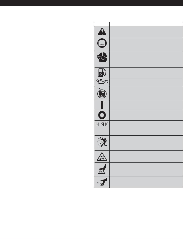
•SAFETY ALERT SYMBOL
Indicates danger, warning or caution. May be used in conjunction with other symbols or pictographs.
•READ OPERATOR'S MANUAL
WARNING: Read the operator’s manual(s) and follow all warnings and safety instructions. Failure to do so can result in serious injury to the operator and/or bystanders.
•WEAR EYE AND HEARING PROTECTION
WARNING: Thrown objects and loud noise can cause severe eye injury and hearing loss. Wear eye protection meeting ANSI Z87.1-1989 standards and ear protection when operating this unit. Use a full face shield when needed.
•UNLEADED FUEL
Always use clean, fresh unleaded fuel
•OIL
Refer to operator’s manual for the proper type of oil.
•DO NOT USE E85 FUEL IN THIS UNIT
WARNING: It has been proven that fuel containing greater than 10% ethanol will likely damage this engine and void the warranty.
•ON/OFF STOP CONTROL
ON / START / RUN
•ON/OFF STOP CONTROL
OFF or STOP
• CHOKE CONTROL
1.• FULL choke position
2.• PARTIAL choke position
3.• RUN choke position
• THROWN OBJECTS AND ROTATING CUTTER CAN CAUSE SEVERE INJURY
WARNING: Small objects can be propelled at high speed, causing injury. Keep away from the rotating rotor.
• KEEP BYSTANDERS AWAY
WARNING: Keep all bystanders, especially children and pets, at least 50 feet (15 m) from the operating area.
• HOT SURFACE WARNING
Do not touch a hot muffler or cylinder. You may get burned. These parts get extremely hot from operation. When turned off they remain hot for a short time.
• SHARP BLADE
WARNING: Sharp blade on cutting attachment shield. To prevent serious injury, do not touch the line cutting blade.
3

KNOW YOUR UNIT
APPLICATIONS
As a trimmer:
•Cutting grass and light weeds.
•Edging
•Decorative trimming around trees, fences, etc.
Other optional accessories may be used.
TOOLS REQUIRED:
•Phillips Screwdriver
•3/8” Socket
Oil Fill Plug |
Spark Plug
Choke Lever
Fuel Cap
Muffler
Starter Rope Grip
Shaft Grip |
|
Primer |
|
|
Bulb |
On/Off Stop Control |
|
|
|
Throttle |
|
D-Handle |
Control |
Air Filter |
|
||
|
Cover |
|
|
|
ASSEMBLY INSTRUCTIONS
INSTALL CUTTING ATTACHMENT SHIELD
WARNING: To prevent serious personal injury, never operate the trimmer without the cutting attachment shield in place.
Use the following instructions if the cutting attachment shield on your unit is not installed. Use only the instructions that apply to the type of shaft and shield that your unit is equipped with.
INSTALLING THE CUTTING HEAD SHIELD
1. Place the cutting |
Cutting |
attachment shield onto the |
Shield |
shaft housing. Be sure the |
|
guard mounting bracket |
|
slides into the slot on the |
|
edge of the cutting shield. |
|
Rotate the shield into |
|
place, counterclockwise |
|
(Fig. 1). The holes in the |
|
guard mounting bracket |
|
and cutting attachment |
|
shield will line up. |
|
2. From inside the cutting attachment shield, push the square bolt through
the hole until the threaded Square Bolt end protrudes through the
guard mounting bracket (Fig. 1).
3. Put the washer on the bolt, then screw the wing nut onto the bolt and tighten.
Mount Bracket
Washer
Wing
Nut
Fig. 1
ADJUSTING THE D-HANDLE
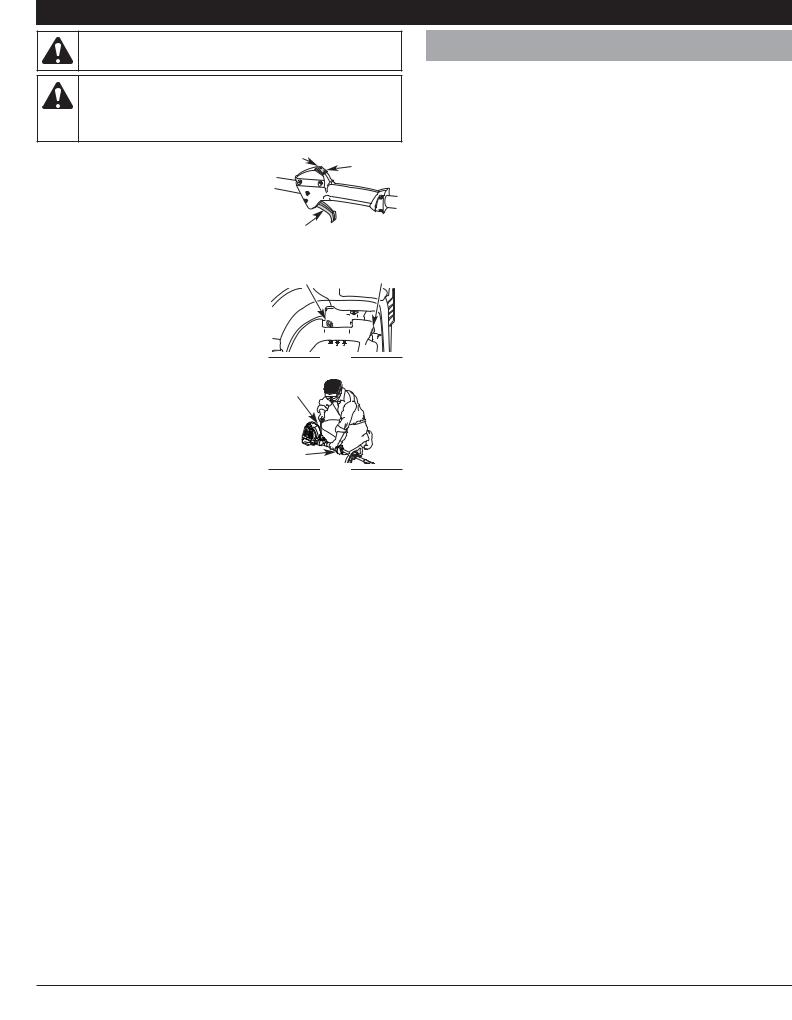
1.Loosen the bolt on the handle just enough to move it (Fig. 2).
2.While holding the unit in the operating position (Fig. 14), move the D-handle to the location that provides the best grip.
3.Tighten the bolt until the D-handle is secure. (Fig. 2)
D-Handle
6 in. 


 (15.24 cm)


 Minimum


 Bolt
Bolt
Fig. 2
EZ-Link™
Line Cutting Blade
Cutting Head Shield


 Cutting Head
4
OIL AND FUEL INFORMATION
WARNING: OVERFILLING OIL CRANKCASE MAY CAUSE SERIOUS PERSONAL INJURY. Check and maintain the proper oil level in the crank case; it is important and cannot be overemphasized. Check the oil before each use and change it as needed. See Changing the Oil.
FUELING THE UNIT
WARNING: Remove fuel cap slowly to avoid injury from fuel spray. Never operate the unit without the fuel cap securely in place.
1. Remove the fuel cap (Fig. 6).
RECOMMENDED OIL TYPE
Using the proper type and weight of oil in the crankcase is extremely important.
Check the oil before each use and change the oil regularly. Failure to use the correct oil, or using dirty oil, can cause premature engine wear and failure.
Use a high-quality SAE 30 weight oil of API (American Petroleum Institute) service class SF, SG, SH.
ADDING OIL TO CRANKCASE: INITIAL USE
NOTE: This unit is shipped without oil. In order to avoid damage to the unit, put oil in the crankcase before you attempt to start the unit.
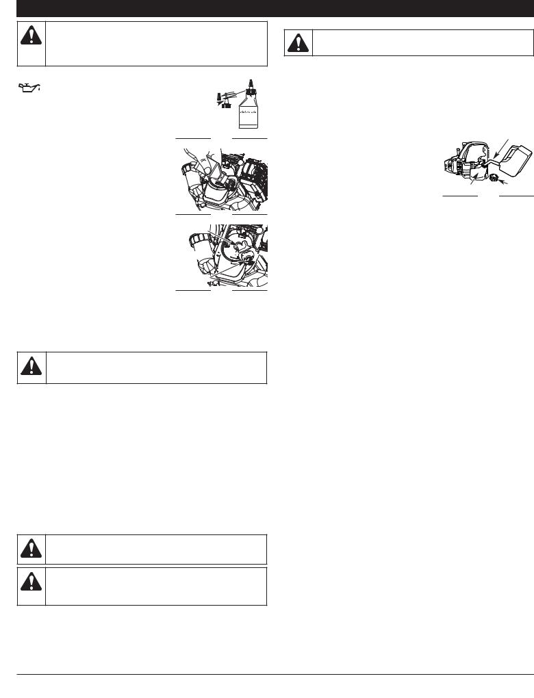
Your unit is supplied with one 3.04 fluid oz. (90 ml) bottle of SAE 30 SF, SG, SH oil (Fig. 3).
NOTE: Save the bottle of oil. It can be used to measure the correct amount during future oil changes. See Changing the Oil.
1.Unscrew the top of the bottle of oil and remove the paper seal covering the opening. Replace the top. Next, cut the tip off the funnel spout (Fig. 3).
2.Tip unit so that the back of the engine is facing up in a vertical position.
Funnel 


Spout
Fig. 3
 Fig. 4
Oil Fill Plug
O-Ring 


Oil Fill Hole
3. Remove the oil fill plug from the crankcase |
Fig. 5 |
|
(Fig. 5). |
||
|
4.Pour the entire bottle of oil into the oil fill hole (Fig. 5). NOTE: Never add oil to the fuel or fuel tank.
5.Wipe up any oil that may have spilled and reinstall the oil fill plug.
Check oil before each use and change as needed. Refer to Checking the Oil Level.
RECOMMENDED FUEL TYPE
WARNING: DO NOT USE E85 FUEL IN THIS UNIT.
It has been proven that fuel containing greater than 10% ethanol will likely damage this engine and void the warranty.
Old fuel is the primary reason for improper unit performance. Be sure to use fresh, clean, unleaded gasoline.
NOTE: This is a four cycle engine. In order to avoid damage to the unit, do not mix oil with gasoline.
Definition of Blended Fuels
Today's fuels are often a blend of gasoline and oxygenates such as ethanol, methanol or MTBE (ether). Alcohol-blended fuel absorbs water. As little as 1% water in the fuel can make fuel and oil separate or form acids when stored. Use fresh fuel (less than 30 days old), when using alcohol-blended fuel.
Using Blended Fuels
If you choose to use a blended fuel, or its use is unavoidable, follow recommended precautions:
•Always use fresh unleaded gasoline
•Use the fuel additive STA-BIL® or an equivalent
•Drain tank and run the engine dry before storing unit
Using Fuel Additives
2.Place the gas container’s spout into the fill hole on the fuel tank (Fig. 6) and fill the tank.
NOTE: Do not overfill the tank.
3.Wipe up any gasoline that may have spilled.
4.Reinstall the fuel cap.
5.Move the unit at least 30 ft. (9.1 m) from the fueling source and site before starting the engine.
Gas Can Spout
NOTE: Dispose of the old gasoline in accordance
with federal, state and local regulations.
Fuel Tank |
Fuel Cap |
Fig. 6
WARNING: Add fuel in a clean, well ventilated outdoor area. Wipe up any spilled fuel immediately. Avoid creating a source of ignition for spilt fuel. Do not start the engine until fuel vapors dissipate.
WARNING: Gasoline is extremely flammable. Ignited vapors may explode. Always stop the engine and allow it to cool before filling the fuel tank. Do not smoke while filling the tank. Keep sparks and open flames at a distance from the area.
The use of fuel additives, such as STA-BIL® Gas Stabilizer or an equivalent, will inhibit corrosion and minimize the formation of gum deposits. Using a fuel additive can keep fuel from forming harmful deposits in the carburetor for up to six (6) months. Add 0.8 oz. (23 ml) of fuel additive per gallon of fuel according to the instructions on the container. NEVER add fuel additives directly to the unit's gas tank.
5
STARTING AND STOPPING INSTRUCTIONS
WARNING: Operate this unit only in a well-ventilated outdoor area. Carbon monoxide exhaust fumes can be lethal in a confined area.
WARNING: Avoid accidental starting. Make sure you are in the starting position when pulling the starter rope (Fig. 10). To avoid serious injury, the operator and unit must be in a stable position while starting. Make sure that any Add-On item is installed correctly and secure before starting the unit.
STARTING INSTRUCTIONS
1.Check the oil level in the crankcase. Refer to
Checking the Oil Level.
2.Fill the fuel tank with fresh, clean unleaded gasoline. Refer to Fueling the Unit.
NOTE: There is no need to turn the unit on. The On/Off Stop Control is in the ON ( I ) position at all times (Fig. 7).
3.Fully press and release the primer bulb 10 times, slowly. Some amount of fuel should be visible in the primer bulb (Fig. 8). If fuel cannot be seen in the bulb, press and release the bulb until fuel is visible.
4.Move the choke lever to Position 1 (Fig. 8).
5.Crouch in the starting position (Fig. 9).
SQUEEZE and HOLD the throttle control for ALL further steps. Pull the starter rope
5 times.
OFF (O)
ON (I)
Throttle Control
|
|
Fig. 7 |
|
|
|
|||||||||||
Choke |
|
Primer |
||||||||||||||
|
|
|
|
|
|
|
|
|
|
|
|
|
|
|||
Lever |
|
|
|
|
|
|
|
|
|
|
|
|
|
|
Bulb |
|
|
|
|
|
|
|
|
|
|
|
|
|
|
|
|
|
|
|
|
|
|
|
|
|
|
|
|
|
|
|
|
|
|
|
|
|
|
|
|
|
|
|
|
|
|
|
|
|
|
|
|
|
|
|
|
|
|
|
|
|
|
|
|
|
|
|
|
|
|
|
|
|
|
|
|
|
|
|
|
|
|
|
|
|
|
Fig. 8
6.Continue to squeeze the throttle control.
Move the choke lever to Position 2 (Fig. 9).
7.Continue to squeeze the throttle control.
Pull the starter rope 3-5 times to start the engine.
8.Continue to squeeze the throttle control.
Allow the engine to warm up for 30-60 seconds.
9.Continue to squeeze the throttle control.
Move the choke lever to Position 3 (Fig. 8).
Starter |
Starting |
Rope |
Position |
Throttle
Control
Fig. 9
10.Continue to squeeze the throttle control. Run the unit for an additional 60 seconds to complete the warm-up. The unit may be used during this step.
NOTE: The unit is properly warmed up when the engine accelerates without hesitation.
IF... the engine hesitates, return the choke lever to Position 2 and continue the warm-up.
IF... the engine does not start, go back to step 3.
IF... the engine fails to start after a few attempts, move the choke lever to Position 3 and squeeze the throttle control. Pull the starter rope 3-8 times. The engine should start. If not, repeat.
IF THE ENGINE IS HOT... Move the choke lever to Position 2, press the primer bulb 10 times, squeeze the throttle control and pull the starter rope until the unit starts. Run the unit for 2-5 minutes. The unit may be used during this time. Then move the choke lever to Position 3.
STOPPING INSTRUCTIONS
1.Release your hand from the throttle control. Allow the engine to cool down by idling.
2.Press and hold the On/Off Stop Control switch in the OFF (O) position until the unit comes to a complete stop (Fig. 7).
IF USING THE OPTIONAL ELECTRIC STARTER
OR POWER START BIT™ ACCESSORY
HOW TO START THE UNIT USING THE ELECTRIC STARTER OR POWER START BIT ACCESSORY
NOTE: This Unit Can Use an Electric Start or Power Start Bit™ Optional Accessory!
Please refer to the Electric Starter or Power Start Bit operator’s manual for proper use of this feature. (Items Sold Separately! Please refer to page 10 of this manual about purchasing these accessories.)
STARTING INSTRUCTIONS
1.Check the oil level in the crankcase. Refer to Checking the Oil Level.
2.Fill the fuel tank with fresh, clean unleaded gasoline. Refer to Fueling the Unit.
NOTE: There is no need to turn the unit on. The On/Off Stop Control is in the ON ( I ) position at all times (Fig. 7).
3.Fully press and release the primer bulb 10 times, slowly. Some amount of fuel should be visible in the primer bulb (Fig. 8). If fuel cannot be seen in the bulb, press and release the bulb until fuel is visible.
4.Move the choke lever to Position 1 (Fig. 8).
5.Crouch in the starting position (Fig. 9). Place the electric starter or Power Start Bit™ into the back of the unit (Fig. 38). Refer to the Operation section of the Electric Starter or Power Start Bit™ operator’s manual.
6.SQUEEZE and HOLD the throttle control for ALL further steps. Press and hold the electric starter or drill ON (I) button for 2 seconds.
7.Continue to squeeze the throttle control. Move the choke lever to Position 2 (Fig. 8).
8.Continue to squeeze the throttle control. Press and hold the electric starter or drill ON (I) button for 2-second intervals until the unit starts.
9.Continue to squeeze the throttle control. Remove the electric starter or drill from the unit.
10.Continue to squeeze the throttle control. Allow the engine to warm up for 30-60 seconds.
11.Continue to squeeze the throttle control. Move the choke lever to Position 3 (Fig. 8).
12.Continue to squeeze the throttle control. Run the unit for an additional 60 seconds to complete the warm-up. The unit may be used during this step.
NOTE: The unit is properly warmed up when the engine accelerates without hesitation.
IF... the engine hesitates, return the choke lever to Position 2 and continue the warm-up.
IF... the engine does not start, go back to step 3.
IF... the engine fails to start after a few attempts, move the choke lever to Position 3 and squeeze the throttle control. Press and hold the electric starter or drill ON (I) button for 2-second intervals until the unit starts.
IF THE ENGINE IS HOT... Move the choke lever to Position 2, press the primer bulb 10 times, squeeze the throttle control, and press and hold the electric starter or drill ON (I) button for 2-second intervals until the unit starts. Run the unit for 2-5 minutes. The unit may be used during this time. Then move the choke lever to Position 3.
STOPPING INSTRUCTIONS
1.Release your hand from the throttle control. Allow the engine to cool down by idling.
2.Press and hold the On/Off Stop Control switch in the OFF (O) position until the unit comes to a complete stop (Fig. 7).
6
OPERATING INSTRUCTIONS
OPERATING THE EZ-LINK™ SYSTEM
WARNING: Before you begin using any attachment, read and understand the manual that came with the attachment. Follow all safety information contained within.
The EZ-Link™ system enables the use of these optional Add-Ons:
Trimmer . . . . . . . . . . . . . . . . . . . . . . . . . . . . . . . . . . . . . . . . . . . . . . . . . AF720 Hedge Trimmer . . . . . . . . . . . . . . . . . . . . . . . . . . . . . . . . . . . . . . . . . . AH720 Brushcutter . . . . . . . . . . . . . . . . . . . . . . . . . . . . . . . . . . . . . . . . . . . . . BC720* Cultivator . . . . . . . . . . . . . . . . . . . . . . . . . . . . . . . . . . . . . . . . . . . . . . . GC720 Edger . . . . . . . . . . . . . . . . . . . . . . . . . . . . . . . . . . . . . . . . . . . . . . . . . . . LE720 Pole Saw . . . . . . . . . . . . . . . . . . . . . . . . . . . . . . . . . . . . . . . . . . . . . . . PS720 Straight Shaft Trimmer . . . . . . . . . . . . . . . . . . . . . . . . . . . . . . . . . . . . . SS725 Turbo Blower . . . . . . . . . . . . . . . . . . . . . . . . . . . . . . . . . . . . . . . . . . . . TB720 *Do NOT use this attachment with an electric powered unit.
Removing the Cutting Attachment or Add-On
WARNING: To avoid serious |
EZ-Link™ |
Release |
personal injury and damage to the |
Coupler |
Button |
|
|
|
unit, shut the unit off before |
|
|
removing or installing add-ons. |
|
|
1.Turn the knob counterclockwise to loosen (Fig. 12).
2.Press and hold the release button (Fig. 10).
3.While firmly holding the upper shaft housing, pull the cutting attachment or add-on straight out of the EZ-Link™ coupler (Fig. 11).
Installing the Cutting Attachment or Add-On
CAUTION: Add-ons are to be used in the primary hole only. Using the wrong hole could lead to personal injury or damage to the unit.
NOTE: Place the unit on the ground or on a work bench to make add-on installation or removal easier.
1.Turn knob counterclockwise to loosen (Fig. 12).
2.While firmly holding the add-on, push it straight into the EZ-Link™ coupler (Fig. 11).
NOTE: Aligning the release button with the guide recess will help installation (Fig. 10).
3. Turn the knob clockwise to tighten (Fig. 12).
Guide Recess
Fig. 10
Primary Hole
Upper Shaft |
Lower Shaft |
|
Housing |
||
Housing |
||
|
||
Fig. 11 |
|
|
90˚ Edging Hole |
|
|
(Trimmer Only) |
|
Knob
Fig. 12
CAUTION: Lock the release button in the primary hole and securely tighten the knob before operating this unit.
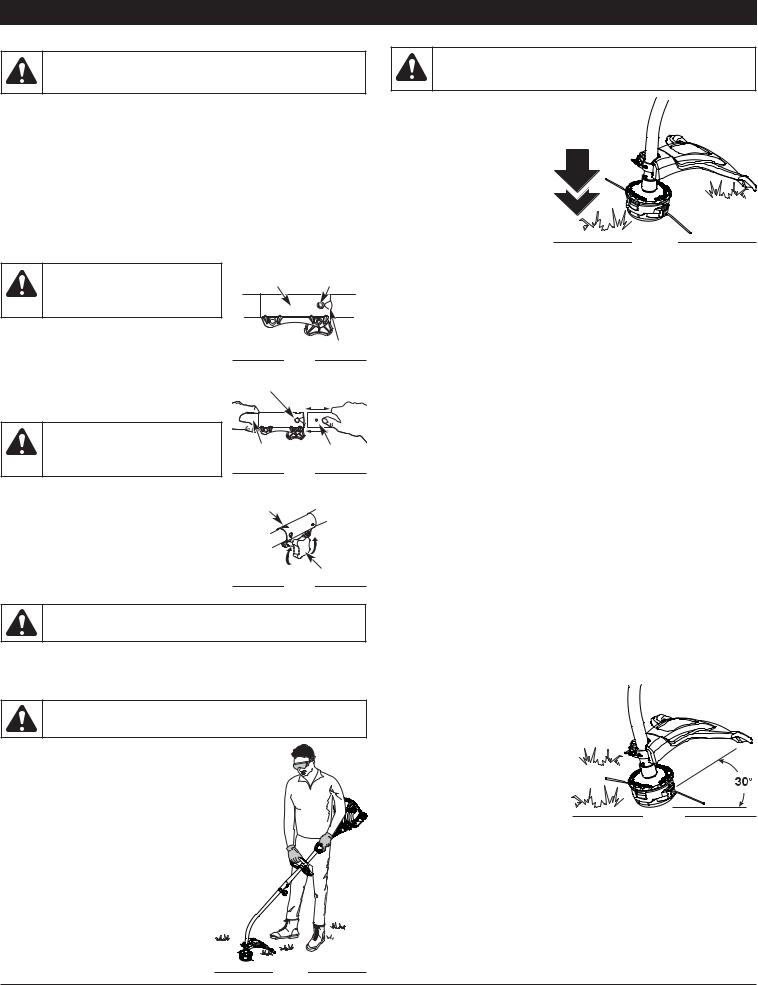
ADJUSTING TRIMMING LINE LENGTH
WARNING: Do not remove or alter the line cutting blade assembly. Excessive line length will make the clutch overheat. This may lead to serious personal injury or damage to the unit.
The Bump Head™ cutting attachment allows you to release trimming line without stopping the engine. To release more line, lightly tap the cutting attachment on the ground (Fig. 14) while operating the trimmer at high speed.
NOTE: Always keep the trimming |
|
line fully extended. Line |
|
release becomes more |
|
difficult as the cutting line |
Fig. 14 |
becomes shorter. |
Each time the head is bumped, about 1 inch (25.4 mm) of trimming line is released. A blade in the cutting attachment shield will cut the line to the proper length if excess line is released.
For best results, tap the Bump Head™ on bare ground or hard soil. If line release is attempted in tall grass, the engine may stall. Always keep the trimming line fully extended. Line release becomes more difficult as the cutting line becomes shorter.
NOTE: Do not rest the Bump Head™ on the ground while the unit is running. Some line breakage will occur from:
•Entanglement with foreign matter
•Normal line fatigue
•Attempting to cut thick, stalky weeds
•Forcing the line into objects such as walls or fence posts
TIPS FOR BEST TRIMMING RESULTS
•For best trimming results, operate unit at full throttle.
•Keep the cutting attachment parallel to the ground.
•Do not force the cutting attachment. Allow the tip of the line to do the cutting, especially along walls. Cutting with more than the tip will reduce cutting efficiency and may overload the engine.
•Cut grass over 8 inches (200 mm) by working from top to bottom in small increments to avoid premature line wear or engine drag.
•Cutting from right to left improves the unit's cutting efficiency. Clippings are thrown away from the operator.
•Slowly move the trimmer into and out of the cutting area at the desired height. Move either in a forward-backward or side-to-side motion. Cutting shorter lengths produces the best results.
•Trim only when grass and weeds are dry.
•The life of your cutting line is dependent upon proper adherence of explained trimming techniques, what vegetation is cut, and where vegetation is cut.
For edging (when using the line head cutting attachment with EZ-Link™ models), lock the release button of the cutting attachment into the 90° edging hole (Fig. 12).
HOLDING THE TRIMMER
WARNING: Always wear eye, hearing, foot and body protection to reduce the risk of injury when operating this unit.
Before operating the unit, stand in the operating position (Fig. 13). Check for the following:
• The operator is wearing eye protection and proper clothing
• With a slightly-bent right arm, the operator’s right hand is holding the shaft grip
• The operator’s left arm is straight, the left hand holding the assist handle
• The unit is at waist level
• The cutting attachment is parallel to the ground and easily contacts the grass without the need to bend over
For example, the line will wear faster when trimming against a foundation wall as opposed to trimming around a tree.
DECORATIVE TRIMMING
Decorative trimming is accomplished by removing all vegetation around trees, posts, fences and more.
Rotate the whole unit so that the cutting attachment is at a 30° angle to the ground (Fig. 15).
Fig. 15
Fig. 13
7
MAINTENANCE AND REPAIR INSTRUCTIONS
WARNING: To prevent serious injury, never perform maintenance or repairs with unit running. Always service and repair a cool unit. Disconnect the spark plug wire to ensure that the unit cannot start.
MAINTENANCE SCHEDULE
Perform these required maintenance procedures at the frequency stated in the table. These procedures should also be a part of any seasonal tune-up.
NOTE: Some maintenance procedures may require special tools or skills. If you are unsure about these procedures take your unit to any non-road engine repair establishment, individual or authorized service dealer.
NOTE: Maintenance, replacement, or repair of the emission control devices and system may be performed by any non-road engine repair establishment, individual or authorized service dealer.
NOTE: Please read the California/EPA statement that came with the unit for a complete listing of terms and coverage for the emissions control devices, such as the spark arrestor, muffler, carburetor, etc.
FREQUENCY |
MAINTENANCE REQUIRED |
SEE |
|
|
|
Every 10 hours |
Clean and oil air filter |
p. 9 |
|
|
|
After 1st 10 hours |
Change oil |
p. 8 |
|
|
|
|
Change oil |
p. 8 |
Every 25 hours |
Check rocker arm to valve clearance and adjust |
p. 9 |
|
Check spark plug condition and gap |
p. 9 |
|
|
|
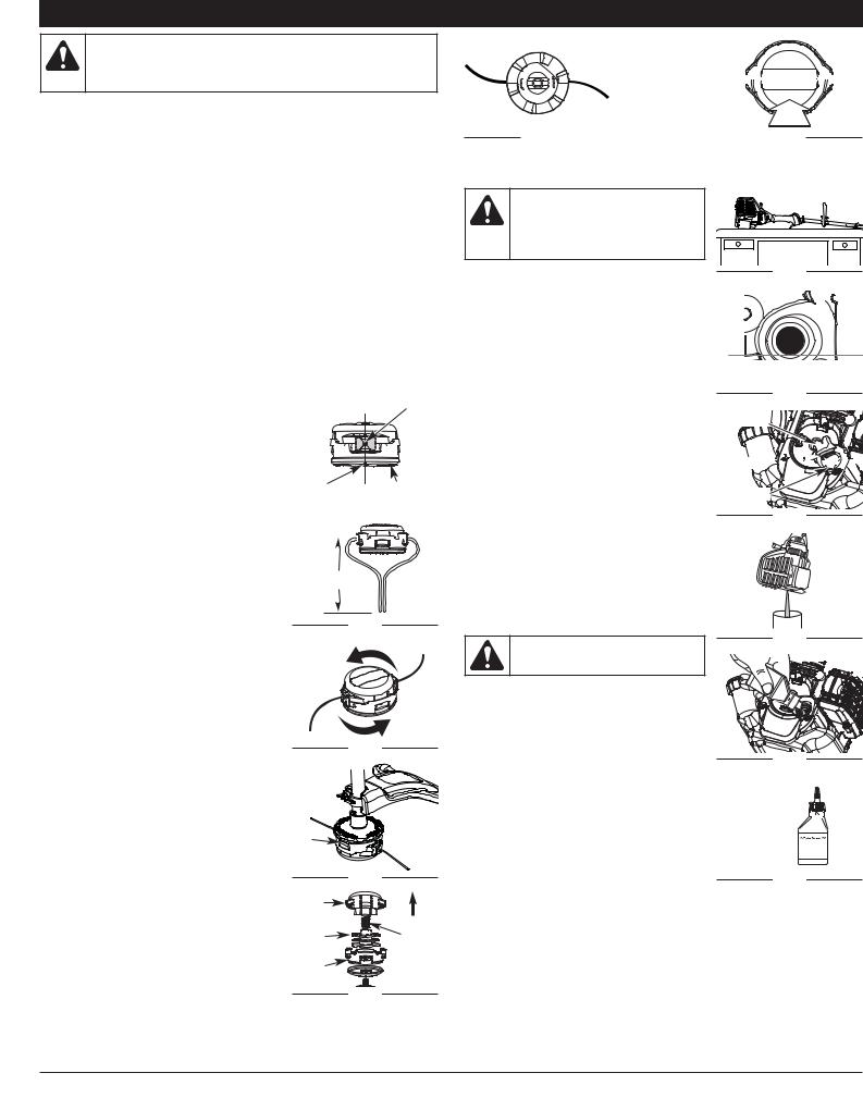
LINE INSTALLATION
Always use original equipment manufacturer 0.095 in. (2.41 mm) replacement line. Other types of line may make the engine overheat or fail.
NOTE: There may be a need to remove the old line prior to installing new line. If so, please refer to Removing the old line or obstructions.
NOTE: Line installation DOES NOT require removal or disassembly of the cutting head.
1.Align the arrows on the cutting head knob with the outer spool eyelets, if they are not already. (Fig. 16)
2.Using 10.5 ft. (3.2 m) of 0.095 in. (2.41 mm) replacement line push an end of the line through one of the eyelets until it protrudes through the opposite side. Continue pushing or pulling the line until the line is evenly distributed, so approximately 5 ft. (1.5 m) is visible from both sides of the cutting head. (Fig. 17)
3.Hold the cutting head knob and turn the cutting head counterclockwise to wind the line around the spool until 5 in. (12.7 cm) is protruding from each side of the cutting head. (Fig. 18)
NOTE: If winding the line from a large spool of line, cut the line from the spool so that it measures 5” from the eyelet.
4.Start the unit and bump the cutting head on the ground until the desired cutting length is achieved.
REMOVING THE OLD LINE OR OBSTRUCTIONS
NOTE: There should only be a need to remove the bump cap if the old line gets jammed or an obstruction preventing the new line from being installed properly.
1.Firmly press in on the tabs that are on each side of the cutting head. (Fig. 19)
NOTE: It may be easier to press in and then up on one tab at a time.
2.Remove the cap either by letting it pop off or a slight wiggle of the cap may be required and pull it off the outer spool (Fig. 20).
3.Remove any old line from the inner reel or obstructions from the outer spool. (Fig. 21)
4.Place the inner reel back into the outer spool (Fig. 20).
Align Eyelet
Arrow |
|
|
Cutting Head Knob |
|
|||||||||||
|
|
|
Fig. 16 |
|
|
|
|
|
|||||||
|
|
|
|
|
|||||||||||
|
|
|
|
|
|
|
|
|
|
|
|
|
|
|
|
|
|
|
|
|
|
|
|
|
|
|
|
|
|
|
|
|
|
|
|
|
|
|
|
|
|
|
|
|
|
|
|
5 Feet
Fig. 17
Fig. 18
Tab |
|
|
Fig. 19 |
Bump |
|
Cap |
UP |
|
|
Inner |
Spring |
Reel |
|
Outer |
|
Spool |
|
|
Fig. 20 |


 PRESS
PRESS


Fig. 21 |
|
|
|
Fig. 22 |
|
|
CHECKING THE OIL LEVEL
WARNING: To prevent extensive engine wear and damage to the unit, always maintain the proper oil level in the crankcase. Never operate the unit with a low oil level.
The importance of checking and maintaining the proper oil level in the crankcase cannot be overemphasized. Check oil before each use:
1.Stop the engine and allow oil to drain into the crankcase.
2.Place the engine on a flat, level surface with the cutting head shield hanging off a work bench or table to get a proper oil level reading (Fig. 23).
Fig. 23
Max Oil Fill Line
3.Keep dirt, grass clippings and other debris out of the engine. Clean the area around the dipstick before removing it.
4.Remove the oil fill plug (Fig. 25).
5.Look into the oil fill hole, use a flashlight if needed. The oil should be just touching the inner most thread (Fig. 24).
6.If the oil level is not touching the inner most thread on the oil fill hole, add a small amount of oil to the oil fill hole and recheck (Fig. 24). Repeat this procedure until the oil level reaches the inner most thread on the oil fill hole.
NOTE: Do not overfill the unit.
NOTE: Make sure the O-ring is in place on the oil fill plug when checking and changing the oil (Fig. 25).
CHANGING THE OIL
CAUTION: Wear gloves to prevent injury when handling the unit.
Change the oil while the engine is still warm. The oil will flow freely and carry away more impurities.
1.Unplug spark plug boot to prevent accidental starting.
2.Remove the oil fill plug.
3.Pour the oil out of the oil fill hole and into a container by tipping the unit to a vertical position (Fig. 26). Allow ample time for complete drainage.
4.Wipe up any oil residue on the unit and clean up any oil that may have spilled. Dispose of the oil according to federal, state and local regulations.
5.Refill the crankcase with 3.04 fluid ounce (90 ml) of SAE 30 SF, SG, SH oil (Fig. 28).
Fig. 24
Oil Fill Plug
O-Ring


Oil Fill Hole
 Fig. 25
Fig. 26
 Fig. 27
Fill Line 

Fig. 28
NOTE: Use the bottle and spout saved from
initial use to measure the correct amount of oil. The top of the label on the bottle measures approximately 3.04 ounces (90 ml) (Fig. 29). Check the level, See Checking the Oil Level. If the level is low, add a small amount of oil and recheck. Do not overfill (Fig. 24).
6.Replace the oil fill plug.
7.Reconnect the spark plug boot.
5.Replace the bump cap by aligning the tabs of the bump cap with the tab lock windows of the outer spool and press down firmly until both tabs snap back into place. (Fig. 22)
To install new line, please refer to the Line Installation section.
8
 Loading...