


Operator’s Manual
2-Cycle Mulching Blower / Vacuum
TB310QS
TABLE OF CONTENTS
Service Information . . . . . . . . . . . . . . . . . . . . . . . . . . . . . . . . . . . . .1 Rules for Safe Operation . . . . . . . . . . . . . . . . . . . . . . . . . . . . . . . . .2 Know Your Unit . . . . . . . . . . . . . . . . . . . . . . . . . . . . . . . . . . . . . . . .4 Assembly Instructions . . . . . . . . . . . . . . . . . . . . . . . . . . . . . . . . . . .4 Oil and Fuel Information . . . . . . . . . . . . . . . . . . . . . . . . . . . . . . . . .4 Starting/Stopping Instructions . . . . . . . . . . . . . . . . . . . . . . . . . . . .4 Operating Instructions . . . . . . . . . . . . . . . . . . . . . . . . . . . . . . . . . . .5 Maintenance & Repair Instructions . . . . . . . . . . . . . . . . . . . . . . . . .6 Cleaning and Storage . . . . . . . . . . . . . . . . . . . . . . . . . . . . . . . . . . .6 Troubleshooting Chart . . . . . . . . . . . . . . . . . . . . . . . . . . . . . . . . . . .7 Specifications . . . . . . . . . . . . . . . . . . . . . . . . . . . . . . . . . . . . . . . . .7 Warranty Information . . . . . . . . . . . . . . . . . . . . . . . . . . . . . . . . . . .28 Parts List . . . . . . . . . . . . . . . . . . . . . . . . . . . . . . . . . . . . . . . . . . . .26
In an effort to reduce the impact on the forests, and reduce carbon and greenhouse gas emissions, MTD is using less paper by reducing the text size of this manual.
PART NO. 769-03704
SAVE THESE INSTRUCTIONS
For service call 1-800-828-5500, or 1-800-668-1238 in Canada to obtain a list of authorized service dealers near you. For more details about your unit, visit our website at www.troybilt.com.
If you have difficulty assembling this product or have any questions regarding the controls, operation or maintenance of this unit, please call the Customer Support Department.
DO NOT RETURN THE UNIT TO THE RETAILER. PROOF OF PURCHASE WILL BE REQUIRED FOR WARRANTY SERVICE.
THIS PRODUCT IS COVERED BY ONE OR MORE U.S. PATENTS. OTHER PATENTS PENDING.
Service on this unit both within and after the warranty period should be performed only by an authorized and approved service dealer.
Before beginning, locate the unit’s model plate. It lists the model and serial numbers of your unit. Refer to the sample plate below and copy the information for future reference.
Copy the model and parent part number here:
Copy the serial number here:
SPARK ARRESTOR NOTE
NOTE: For users on U.S. Forest Land and in the states of California, Maine, Oregon and Washington. All U.S. Forest Land and the state of California (Public Resources Codes 4442 and 4443), Oregon and Washington require, by law that certain internal combustion engines operated on forest brush and/or grass-covered areas be equipped with a spark arrestor, maintained in effective working order, or the engine be constructed, equipped and maintained for the prevention of fire. Check with your state or local authorities for regulations pertaining to these requirements. Failure to follow these requirements could subject you to liability or a fine. This unit is factory equipped with a spark arrestor. If it requires replacement, ask your LOCAL SERVICE DEALER to install the
Accessory Part #753-05709 Mufler Assembly.
CALIFORNIA PROPOSITION 65
WARNING
THE ENGINE EXHAUST FROM THIS PRODUCT CONTAINS CHEMICALS KNOWN TO THE STATE OF CALIFORNIA TO CAUSE CANCER, BIRTH DEFECTS OR OTHER REPRODUCTIVE HARM.
All information, illustrations, and specifications in this manual are based on the latest product information available at the time of printing. We reserve the right to make changes at any time without notice.
Copyright© 2008 MTD SOUTHWEST INC, All Rights Reserved.
(2/08)

RULES FOR SAFE OPERATION
The purpose of safety symbols is to attract your attention to possible dangers. The safety symbols, and their explanations, deserve your careful attention and understanding. The safety warnings do not by themselves eliminate any danger. The instructions or warnings they give are not substitutes for proper accident prevention measures.
SYMBOL MEANING
SAFETY ALERT: Indicates danger, warning or caution. Attention is required in order to avoid serious personal injury. May be used in conjunction with other symbols or pictographs.
NOTE: Advises you of information or instructions vital to the operation or maintenance of the equipment.
DANGER: Failure to obey a safety warning will result in serious injury to yourself or to others. Always follow the safety precautions to reduce the risk of fire, electric shock and personal injury.
WARNING: Failure to obey a safety warning can result in injury to yourself and others. Always follow the safety precautions to reduce the risk of fire, electric shock and personal injury.
CAUTION: Failure to obey a safety warning may result in property damage or personal injury to yourself or to others. Always follow the safety precautions to reduce the risk of fire, electric shock and personal injury.
Read the Operator’s Manual and follow all warnings and safety instructions. Failure to do so can result in serious injury to the operator and/or bystanders.
FOR QUESTIONS, CALL 1-800-828-5500 IN U.S. OR 1-800-668-1238 in CANADA
• IMPORTANT SAFETY INSTRUCTIONS • READ ALL INSTRUCTIONS
WARNING: When using the unit, you must follow the safety rules. Please read these instructions before operating the unit in order to ensure the safety of the operator and any bystanders.
Please keep these instructions for later use.
BEFORE OPERATING
•Read the instructions carefully. Be familiar with the controls and proper use of the unit.
•Do not operate this unit when tired, ill, or under the influence of alcohol, drugs, or medication.
•Children and teens under the age of 15 must not use the unit, except for teens guided by an adult.
•All guards and safety attachments must be installed properly before operating the unit.
•Inspect the unit before use. Replace damaged parts. Check for fuel leaks. Make sure all fasteners are in place and secure. Replace parts that are cracked, chipped, or damaged in any way. Do not operate the unit with loose or damaged parts.
•Carefully inspect the area before starting the unit. Remove all debris and hard or sharp objects such as glass, wire, etc.
•Clear the area of children, bystanders, and pets. At a minimum, keep all children, bystanders, and pets outside a 50 feet (15 m.) radius; there still may be a risk to bystanders from thrown objects. Bystanders should be encouraged to wear eye protection. If you are approached, stop the unit immediately.
SAFETY WARNINGS FOR GAS UNITS
WARNING: Gasoline is highly flammable, and its vapors can explode if ignited. Take the following precautions:
•Store fuel only in containers specifically designed and approved for the storage of such materials.
•Avoid creating a source of ignition for spilled fuel. Do not start the engine until fuel vapors dissipate.
•Always stop the engine and allow it to cool before filling the fuel tank. Never remove the cap of the fuel tank, or add fuel, when the engine is
hot. Never operate the unit without the fuel cap securely in place. Loosen the fuel tank cap slowly to relieve any pressure in the tank.
•Mix and add fuel in a clean, well-ventilated outdoor area where there are no sparks or flames. Slowly remove the fuel cap only after stopping engine. Do not smoke while fueling or mixing fuel. Wipe up any spilled fuel from the unit immediately. Always wipe unit dry before using.
•Move the unit at least 30 feet (9.1 m) from the fueling source and site before starting the engine. Do not smoke or allow sparks and open flames near the area while adding fuel or operating the unit.
WHILE OPERATING
•Never start or run the unit inside a closed room or building. Breathing exhaust fumes can kill. Operate this unit only in a well-ventilated outdoor area.
•To reduce the risk of injury associated with thrown objects, wear safety glasses or goggles that are marked as meeting ANSI Z87. standards.
•Never run the unit without the the proper equipment attached. When using this unit, always install the blower/vacuum tubes and vacuum bag depending on model. Make sure the vacuum bag is completely zipped closed.
•To reduce the risk of hearing loss associated with sound level(s), always wear ear/hearing protection when operating this unit.
•Wear heavy, long pants, boots, and gloves. Do not wear short pants, sandals, or go barefoot.
•To avoid static electricity shock, do not wear rubber gloves or any other insulated gloves while operating this unit.
•To reduce the risk of injury associated with objects being drawn into rotating parts, do not wear loose clothing, jewelry, scarves, and the like. Secure hair above shoulder level.
•Wear a face or dust mask if the operation is dusty. Long sleeve shirts are recommended.
•Use the unit only in daylight or good artificial light.
•Keep outside surfaces free from oil and fuel.
•Avoid accidental starting. Be in the starting position whenever pulling the starter rope. The operator and unit must be in a stable position while starting. Refer to Starting/Stopping Instructions.
•Do not set unit on any surface except a clean, hard area while engine is running. Debris such as gravel, sand, dust, grass, etc. could be picked up by the air intake and thrown out by the discharge opening, damaging unit, property, or causing serious injury to bystanders or operator.
•Use the right tool. Only use this tool for the purpose intended.
•Do not force unit. It will do the job better and with less likelihood of injury at a rate for which it was designed.
•Do not overreach or use from unstable surfaces such as ladders, trees, steep slopes, rooftops, etc. Always keep proper footing and balance.
•Always hold the unit with a firm grip when operating.
•Keep hands, face, and feet at a distance from all moving parts. Do not touch or try to stop the impeller when it is rotating. Do not operate without guards in place.
•Do not put any object into openings. Do not use with any opening blocked; keep free of dirt, debris, and anything that may reduce the air flow.
•Do not touch the engine or muffler. These parts get extremely hot from operation. When turned off they remain hot for a short time.
•Do not operate the engine faster than the speed needed to do the job. Do not run the engine at high speed when not in use.
•Always stop the engine when operation is delayed or when walking from one location to another.
•Stop the engine for maintenance, repair, to install or remove the blower tubes or vacuum attachments. The unit must be stopped and the impeller no longer turning to avoid contact with the rotating blades.
•Use only original equipment manufacturer replacement parts when servicing this unit. These parts are available from your authorized service dealer. Do not use unauthorized parts, accessories, or attachments for this unit. Doing so could lead to serious injury to the user, or damage to the unit, and void your warranty.
•Never use this unit for spreading chemicals, fertilizers or other substances which may contain toxic materials.
•To reduce fire hazard, replace faulty muffler and spark arrestor, keep the engine and muffler free from grass, leaves, excessive grease or carbon build up.
2

RULES FOR SAFE OPERATION
WHILE OPERATING UNIT AS A BLOWER
•Never point the blower in the direction of people or pets, or in the direction of windows. Always direct the blowing debris away from people, animals, and windows. Use extra caution when blowing debris near solid objects such as trees, automobiles, walls, etc.
WHILE OPERATING UNIT AS A VACUUM
•Avoid situations that could catch the vacuum bag on fire. Do not operate near an open flame. Do not vacuum warm ash from fireplaces, barbecue pits, brush piles, etc. Do not vacuum discarded cigars or cigarettes unless the cinders are completely cool.
•The unit is designed to pickup dry material such as leaves, grass, small twigs, and bits of paper. Do not attempt to vacuum wet debris and/or standing water as this may result in damage to the blower/ vacuum. To avoid severe damage to the impeller, do not vacuum metal, broken glass, etc.
OTHER SAFETY WARNINGS
•Always disconnect the spark plug before performing maintenance or accessing movable parts.
•Never store the unit, with fuel in the tank, inside a building where fumes may reach an open flame (pilot lights, etc.) or sparks (switches, electrical motors, etc.).
•Allow the engine to cool before storing or transporting. Be sure to secure the unit while transporting.
•Store the unit in a dry place, either locked up or up high to prevent unauthorized use or damage. Keep out of the reach of children.
•Never douse or squirt the unit with water or any other liquid. Keep handles dry, clean, and free from debris. Clean after each use, see Cleaning and Storage instructions.
•Keep these instructions. Refer to them often and use them to instruct other users. If you loan this unit to others, also loan these instructions to them.
SPECIAL NOTE: Exposure to vibrations through prolonged use of gasoline powered hand tools could cause blood vessel or nerve damage in the fingers, hands, and joints of people prone to circulation disorders or abnormal swelling. Prolonged use in cold weather has been linked to blood vessel damage in otherwise healthy people. If symptoms occur such as numbness, pain, loss of strength, change in skin color or texture, or loss of feeling in the fingers, hands or joints, discontinue use of this tool and seek medical attention. An anti-vibration system does not guarantee avoidance of these problems. Users who operate power tools on a regular basis must closely monitor their physical condition and the condition of this tool.
SAVE THESE INSTRUCTIONS
This operator's manual describes safety and international symbols and pictographs that may appear on this product. Read the operator's manual for complete safety, assembly, operating and maintenance and repair information.
SYMBOL MEANING
•SAFETY ALERT SYMBOL
Indicates danger, warning or caution. May be used in conjunction with other symbols or pictographs.
•WARNING - READ OPERATOR'S MANUAL
Read the operator’s manual(s) and follow all warnings and safety instructions. Failure to do so can result in serious injury to the operator and/or bystanders.
•WEAR EYE AND HEARING PROTECTION
WARNING: Thrown objects and loud noise can cause severe eye injury and hearing loss. Wear eye protection meeting ANSI Z87.1-1989 standards and ear protection when operating this unit. Use a full face shield when needed.
•UNLEADED FUEL
Always use clean, fresh unleaded fuel
RULES FOR SAFE OPERATION
• KEEP BYSTANDERS AWAY
WARNING: Keep all bystanders, especially children and pets, at least 50 feet (15 m.) from the operating area.
• HOT SURFACE WARNING
Do not touch a hot muffler or cylinder. You may get burned. These parts get extremely hot from operation. When turned off they remain hot for a short time.
• OIL
Refer to operator’s manual for the proper type of oil.
•BLOWERS – ROTATING IMPELLER BLADES CAN CAUSE SEVERE INJURY
WARNING: Stop the engine and allow the impeller to stop before opening the vacuum door, installing or changing tubes or bag, or before cleaning or performing any maintenance.
•BLOWER/VACUUM MODE QUICKSHIFT® LEVER
A - Vacuum mode B - Blower mode
•THROTTLE CONTROL
Indicates “HIGH” or “FASTEST” speed.
•THROTTLE CONTROL
Indicates “IDLE”, “LOW” or “SLOWEST” speed
•ON/OFF STOP CONTROL
ON / START / RUN
•ON/OFF STOP CONTROL
OFF or STOP
• THROWN OBJECTS AND ROTATING CUTTER CAN CAUSE SEVERE INJURY
WARNING: Small objects can be propelled at high speed, causing injury. Keep away from the rotating rotor.
3

KNOW YOUR UNIT
APPLICATION
As a blower:
•Cleaning yards, garages, driveways, porches, patios, around walls, fences and more
As a vacuum:
•Picking up leaves and other light debris
Vacuum Inlet |
Blower/ Vacuum |
|
Tube |
||
|
Blower Outlet
Vacuum Bag
Hook
Blower/Vacuum Mode
Quickshift™ Lever
On/Off Stop |
|
Control |
Throttle |
|
|
Fuel Cap |
Control |
|
Starter Rope
Grip
Vacuum Bag |
Blue Choke |
Zipper |
|
|
Lever |
Vacuum Bag |
Air Filter |
|
Cover |
|
Primer Bulb |
|
Muffler |
|
Spark Plug |
ASSEMBLY INSTRUCTIONS
ATTACHING AND REMOVING THE BLOWER/VACUUM TUBE
WARNING: To avoid serious personal injury, the blower/vacuum tube and vacuum bag must be used when operating this unit.
Attaching
NOTE: The blower/vacuum tube comes unassembled on this unit. Installation is required to provide safe and easy use for the operator.
WARNING: To prevent serious personal injury, stop the engine and allow the impeller to stop before attaching or removing tubes.
1.Remove the screws and nuts provided from the hardware pack.
2.Insert the blower/vacuum tube all the way into the opening on the motor housing until the holes in the tabs on the blower/vacuum tube align with the screw holes in the housing (Fig. 1).
3.Insert the 2 (two) 8-32 x 3/4” slotted T20 Torx screws into the right side of the motor housing and the 2 (two) nuts into the left side of the motor housing (Fig. 1).
4.Tighten the screws firmly. Do not over-tighten.
5.Install the 2 (two) remaining self-tapping 8-16 x 3/4” slotted T20 Torx screws into the holes on either side of the housing (Fig. 1). Tighten until snug, do not over-tighten.
Engine |
Nut |
Housing |
Screw |
Blower/ Vacuum |
|
Tube |
|
Fig. 1 |
|
Screw |
Screw & |
Screw & |
Nut |
Nut |
|
Fig. 2 |
Removing |
Vacuum |
|
Bag Hook |
WARNING: To prevent serious personal injury, stop the engine and allow the impeller to stop before attaching or removing tubes.
NOTE: It may be necessary to remove the blower/vacuum tube to clear a blocked tube or impeller.
1.Remove the 2 (two) self-tapping screws from either side of the housing.
2.Remove the 2 (two) screws and nuts holding the blower/vacuum tube on the housing (Fig. 2).
NOTE: Keep the hardware in a safe place for future use.
3.Remove the blower/vacuum tube from the motor housing.
4.Replace blower/vacuum tube before use.
ATTACHING AND REMOVING THE VACUUM BAG
Attaching
1.Attach the vacuum bag to the vacuum bag hook on the blower/vacuum tube (Fig. 3).
2.Slide the vacuum bag tube over the debris exhaust tube on the housing. Push the tube until the latching tabs on both sides click into place, securing the bag on the unit (Fig. 4).
Removing
1.Press the latching tabs on both sides of the vacuum bag tube and pull the vacuum bag down from the unit (Fig. 5).
2.Detach the vacuum bag from the vacuum bag hook.
Fig. 3
Debris Exhaust
Tube
Vacuum Bag
Tube
Vacuum Bag
 Zipper
Fig. 4
Latching Tabs


 PRESS IN PRESS IN


Fig. 5
ASSEMBLY INSTRUCTIONS
INSTALLING THE SHOULDER HARNESS (OPTIONAL)
WARNING: To prevent serious personal injury, stop the engine and allow the impeller to stop before attaching or removing tubes.
The shoulder strap is an optional accessory.
1. Push the strap through the center of the buckle.
2. Pull the strap over the cross bar and down through the slot
in the buckle (Fig. 6). |
Clip |
|
3. Snap the clip on to the support fittings on the front or back of the handle. Clip to the front portion of the handle when
using the unit as a blower, and clip to the back portion of the handle when using the unit as a vacuum (Fig. 7).
4.While standing in the operating position adjust length to fit the operator’s size. Pull tab to lengthen, pull strap to shorten (Fig 8).
Attach Here
for Blower Attach Here for Vacuum
Fig. 7 |
Fig. 8 |
OIL AND FUEL INFORMATION
OIL AND FUEL MIXING INSTRUCTIONS
Old and/or improperly mixed fuel are the main reasons for the unit not running properly. Be sure to use fresh, clean unleaded fuel. Follow the instructions carefully for the proper fuel/oil mixture.
Definition of Blended Fuels
Today's fuels are often a blend of gasoline and oxygenates such as ethanol, methanol, or MTBE (ether). Alcohol-blended fuel absorbs water. As little as 1% water in the fuel can make fuel and oil separate. It forms acids when stored. When using alcohol-blended fuel, use fresh fuel (less than 60 days old).
Using Blended Fuels
If you choose to use a blended fuel, or its use is unavoidable, follow recommended precautions:
•Always use the fresh fuel mix explained in your operator's manual
•Always agitate the fuel mix before fueling the unit
•Drain the tank and run the engine dry before storing the unit
Using Fuel Additives
The bottle of 2-cycle oil that came with your unit contains a fuel additive which will help inhibit corrosion and minimize the formation of gum deposits. It is recommended that you use our 2-cycle oil with this unit. If unavailable, use a good 2-cycle oil de-signed for air-cooled engines along with a fuel additive, such as STA-BIL® Gas Stabilizer or an equivalent. Add 0.8 oz. (23 ml.) of fuel additive per gallon of fuel according to the instructions on the container. NEVER add fuel additives directly to the unit's fuel tank.
CAUTION: For proper engine operation and maximum reliability, pay strict attention to the oil and fuel mixing instructions on the 2-cycle oil container. Using improperly mixed fuel can severely damage the engine.
Thoroughly mix the proper ratio of 2-cycle engine oil with unleaded gasoline in a separate fuel can. Use a 40:1 fuel/oil ratio. Do not mix them directly in the engine fuel tank. See the table below for specific gas and oil mixing ratios.
NOTE: One gallon (3.8 liters) of unleaded gasoline mixed with one 3.2 oz. (95 ml.) bottle of 2-cycle oil makes a 40:1 fuel/oil ratio.
WARNING: Gasoline is extremely flammable. Ignited vapors may explode. Always stop the engine and allow it to cool before filling the fuel tank. Do not smoke while filling the tank. Keep sparks and open flames at a distance from the area.
NOTE: Dispose of the old fuel/oil mix in accordance to Federal, State and Local regulations.
|
|
UNLEADED GAS |
2 CYCLE OIL |
|
|
1 GALLON US |
3.2 FL. OZ. |
(3.8 LITERS) |
(95 ml) |
|
|
1 LITER |
25 ml |
|
|
MIXING RATIO - 40:1
WARNING: Remove fuel cap slowly to avoid injury from fuel spray. Never operate the unit without the fuel cap securely in place.
WARNING: Add fuel in a clean, well ventilated outdoor area. Wipe up any spilled fuel immediately. Avoid creating a source of ignition for spilt fuel. Do not start the engine until fuel vapors dissipate.
STARTING/STOPPING INSTRUCTIONS
WARNING: Operate this unit only in a well-ventilated outdoor area. Carbon monoxide exhaust fumes can be lethal in a confined area.
WARNING: Avoid accidental starting. Make sure you are in the starting position when pulling the starter rope (Fig. 11). To avoid serious injury, the operator and unit must be in a stable position while starting.
STARTING INSTRUCTIONS |
Throttle Control |
Slow |
Fast |
1. Mix gas with oil. Fill fuel tank with fuel/oil mixture. See Oil and Fuel Mixing Instructions.
WARNING: To avoid serious personal injury, always remove the vacuum bag prior to refueling the unit. The bag may become a fire hazard when saturated with fuel.
NOTE: The throttle control will remain in the position
it’s placed until moved. Fast position is to the
Fig. 9
right. Also, there is no need to turn the unit on.
The On/Off Stop Control is in the ON (I) position at all times.
4

|
STARTING/STOPPING INSTRUCTIONS |
2. |
Set the blower/vacuum mode Quickshift™ lever to Position 1 |
|
the up position (Blower Mode). See Operating as a |
|
Blower. This prevents the vacuum bag from filling up |
|
while starting the engine. |
3. |
Fully press and release the primer bulb 10 times, |
|
slowly. Some amount of fuel should be visible in the |
|
primer bulb and fuel lines (Fig. 10). If you can not |
|
see fuel in the bulb, press and release the bulb as |
|
many times as it takes before you can see fuel in it. |
4. With the unit in the starting position (Fig. 11), move the choke lever to Position 1 (Fig. 10) and the throttle lever to the fast position (  ) (Fig. 9).
5.Pull the starter rope out with a controlled and steady motion 5 times. If the engine attempts to run before the fifth pull, proceed to step 6 (Fig. 11).
NOTE: The engine will not run with the choke lever in Position 1 (Fig 10).
NOTE:The unit uses Spring Assist Starting™, which 
 significantly reduces the effort required to start the


 engine. You must pull the starter rope out far enough
  to hear the engine attempt to start. There is no need
 to pull the rope brisklythere is no harsh resistance
 when pulling. Be aware that this starting method is
vastly different from (and much easier than) what you may be used to.
6.Move the choke lever to Position 2, (Fig. 10).
Position 2
Position 3
Choke
Lever
Primer Bulb
7.Pull the starter rope out with a controlled and steady motion until the unit starts. (Fig. 11)
8.Keep the throttle control in the fast position (  ) and let the engine warm up for 15 to 30 seconds.
NOTE: Engine may take longer to warm up and reach maximum operating speed at cooler temperatures.
9.Once the engine is warmed up, move the choke lever to Position 3, (Fig. 10). The unit is ready for use.

 IF... The engine does not start, go back to step 3.
STOPPING INSTRUCTIONS
1.Move the throttle control to the idle position (  ). Allow the engine to cool down by idling.
2.Press and hold On/Off Stop Control in the OFF (O) position until engine comes to a complete stop.
OPERATING INSTRUCTIONS
HOLDING THE BLOWER/VACUUM
Before operating the unit, stand in the operating position. (Fig. 12). Check for the following:
•Operator is wearing proper clothing, such as boots, safety glasses or goggles, ear/ hearing protection, gloves, long pants and long sleeve shirt
WARNING: Always wear eye, hearing, foot and body protection to reduce the risk of injury when operating this unit.
•If the conditions are dusty, the operator should be wearing a dust mask or face mask
•The unit is in good working condition
•The tubes and guards are in place and secure
WARNING: Always wear eye, hearing, foot and body protection to reduce the risk of injury when operating this unit.
OPERATING TIPS
• Be sure the vacuum bag is zipped closed before operating the unit.
• Assure the unit is not directed at anybody or at any loose debris before starting the unit.
• Verify that the unit is in good working condition. Make sure the tubes and guards are in place and secure.
• Always hold the unit with both hands when operating. Keep a firm grip on both the front and rear handle or grips.
• To reduce the risk of hearing loss associated with sound |
|
level(s), hearing protection is required. |
Fig. 12 |
•Operate power equipment only at reasonable hours— not early in the morning or late at night when people might be disturbed. Comply with times listed in local ordinances. Usual recommendations are 9:00 am to 5:00 pm, Monday through Saturday.
•To reduce noise levels, limit the number of pieces of equipment used at any one time.
•To reduce noise levels, operate power blowers at the lowest possible speed to do the job.
•Check your equipment before operation, especially the muffler, air intakes and air filters.
•Use rakes and brooms to loosen debris before blowing.
•In dusty conditions, slightly dampen surfaces or use a mister attachment when water is available.
•Conserve water by using power blowers instead of hoses for many lawn and garden applications, including areas such as gutters, screens, patios, grills, porches and gardens.
•Watch out for children, pets, open windows or freshly washed cars, and blow debris safely away.
•Use the full blower nozzle extension so the air stream can work close to the ground.
•Clean up after using blowers and other equipment. Dispose of debris appropriately.
OPERATING AS A BLOWER
Converting to a Blower
1.Start the engine. See Starting/Stopping Instructions.
2.Set the blower/vacuum mode Quickshift® lever to the up position (Blower Mode) (Fig. 13).
NOTE: Never use the unit with the lever in a position half way between either mode.
Vacuum
 Mode
Mode
Blower
Mode
Quickshift®
Lever
Fig. 13
OPERATING INSTRUCTIONS
Blower Operating Procedures
Hold the blower as shown in Figures 14, 15, and 16. Sweep from side to side with the nozzle several inches above the ground or floor. Slowly advance the unit, keeping the accumulated pile of debris in front of you.
Most dry blowing operations are better suited to low speeds, rather than high. High speed blowing is a better way to move heavier items like large debris or gravel.
1 Use the blower for trees, shrubs, flower beds and hard-to- clean areas (Fig. 14).
2. |
Use the unit around buildings and for other normal cleaning |
Fig. 14 |
|
procedures (Fig. 15). |
3. Use the blower around walls, overhangs, fences and screens (Fig. 16).
OPERATING AS A VACUUM
Converting to Vacuum
1. Start engine. See Starting/Stopping Instructions.
2. Set the blower/vacuum mode Quickshift® lever to the down position (Vacuum Mode) (Fig. 13).
NOTE: Never use the unit with the lever in a position half way between either mode.
Fig. 15
WARNING: Always wear eye, hearing, foot and body protection to reduce the risk of injury when operating this unit.
Vacuum Operation Procedures
Check for the following before operating the unit:
• Operator is wearing proper clothing, such as boots, safety glasses or goggles, ear/hearing protection, gloves, long pants
and long sleeve shirt
• If the conditions are dusty, operator is equipped with a dust
mask or face mask
Fig. 16
•The unit is in good working condition-- the vacuum tubes and
vacuum bag are in place and secure.
• The shoulder harness is in place and correctly adjusted
Use the unit for vacuuming up light debris like leaves and paper.
Hold the vacuum, tilting the suction tube slightly (2-4 in or 50-100 mm), and use a sweeping action to collect light debris (Fig. 17). The debris will flow into the vacuum bag. Items such as small leaves and small twigs will be mulched as they pass through the fan housing, allowing the vacuum bag to hold more debris.
When the bag is full, suction will noticeably decrease. Turn off the unit before removing the bag. Remove and unzip the bag and
empty the contents before continuing. |
Fig. 17 |
|
|
||
NOTE: |
Empty the bag after each use to avoid deterioration |
|
|
and obstructing air flow, which will reduce the |
|
|
performance of the vacuum. |
|
PATIO HEAD |
|
|
NOTE: |
To use the patio head, the unit must be operated as a |
|
|
vacuum. See the Operating as a Vacuum section of |
|
|
your manual. |
|
Installation |
|
|
1. |
Turn the unit so that the blower/vacuum tube openings |
|
|
point straight up (Fig. 18). |
Fig. 18 |
|
|
|
2.Place the round opening of the patio head into the round
vacuum opening (Fig. 19).
3. Press down until the patio head seats into place.
Operation
Hold the vacuum, tilting the blower/vacuum tube down. The Patio Head should roll without scraping, adjust the angle of the tube so that the Patio
Head opening runs parallel to the ground. Use a forward and backward motion to vacuum up debris (Fig. 20). Small leaves and twigs will flow into the vacuum bag and be mulched as they pass through the fan housing, allowing the vacuum bag to hold more debris. DO NOT attempt to
vacuum up materials that are larger than the Patio Head Openings.
Fig. 19
When the bag is full, suction will noticeably decrease. Turn off the unit before removing the bag. Unzip the bag and empty the contents before continuing.
Removal
1. Turn the unit so that the blower/vacuum tube openings are straight up (Fig. 18).
2. Place one hand on the blower part of the tube and grip the patio head with the other.
3. Pull the patio head straight up.
CLEARING A BLOCKED TUBE / IMPELLER |
|
|
1. |
Press the On/Off Stop control down in the STOP (O) |
Fig. 20 |
|
position until the engine comes to a complete stop (Fig. 9). |
|
2.Disconnect the spark plug wire to prevent the unit from starting.
3.Remove the blower/vacuum tube and the vacuum bag.
4.Carefully remove material blocking the tube or impeller. Inspect the blades to assure no damage has occurred. Rotate the impeller blades by hand to assure the blockage is completely cleared.
5.Reinstall the vacuum bag and blower/ vacuum tube.
6.Reconnect the spark plug wire.
EMPTYING THE VACUUM BAG
NOTE: Empty the bag after each use to avoid deterioration and obstructing air flow, which will reduce the performance of the vacuum.
1.While pressing the latching tabs on both sides of the vacuum bag tube, pull the vacuum bag down off the unit (Fig. 5).
2.Detach the vacuum bag from the vacuum bag hook.
3.Unzip the bag and empty the contents into a garbage bag or container.
4.Turn the bag inside out after initial emptying and vigorously shake out dust and debris.
5.Return the bag to outside in, zip the bag closed and reinstall vacuum bag.
5
MAINTENANCE AND REPAIR INSTRUCTIONS
MAINTENANCE SCHEDULE
Perform these required maintenance procedures at the frequency stated in the table. These procedures should also be a part of any seasonal tune-up.
NOTE: Some maintenance procedures may require special tools or skills. If you are unsure about these procedures take your unit to any non-road engine repair establishment, individual or authorized service dealer.
NOTE: Maintenance, replacement, or repair of the emission control devices and system may be performed by any non-road engine repair establishment, individual or authorized service dealer.
WARNING: To prevent serious injury, never perform maintenance or repairs with unit running. Always service and repair a cool unit. Disconnect the spark plug wire to ensure that the unit cannot start.
In order to assure peak performance of your engine, inspection of the engine exhaust port may be necessary after 50 hours of operation. If you notice lost RPM, poor performance or general lack of acceleration, this service may be required. If you feel your engine is in need of this inspection, refer service to any non-road engine repair establishment, individual or authorized service dealer for repair. DO NOT attempt to perform this process yourself as engine damage may result from contaminants involved in the cleaning process for the port.
FREQUENCY |
MAINTENANCE REQUIRED |
SEE |
|
|
|
Before starting engine |
Fill fuel tank with fresh fuel |
Page 4 |
|
|
|
Every 10 hours |
Clean and re-oil air filter |
Page 6 |
|
|
|
Every 25 hours |
Check and clean spark arrestor |
Page 6 |
|
Check spark plug condition and gap |
Page 6 |
|
|
|
Every 50 hours |
Inspect exhaust port and spark arrestor screen for clogging |
Page 6 |
|
or obstruction to assure maximum performance levels |
|
|
|
|
AIR FILTER MAINTENANCE |
Blue Choke |
|
|
|
WARNING: To avoid serious personal injury, |
Lever |
|
|
|
Position 2 |
|
|
always turn your unit off and allow it to cool |
|
|
|
before you clean or service it. |
|
|
Removing the Air Filter/Muffler Cover |
Screws |
Screws |
|
|
|
||
1. |
Place the choke lever in Position 2. |
|
|
NOTE: |
The choke lever must be in Position 2 (Fig. 21) to |
|
|
|
remove the air filter/muffler cover. |
|
|
2. |
Remove the four (4) screws securing the air filter/muffler |
|
Fig. 21 |
|
cover (Fig. 21). Use a T20 Torx bit screwdriver. |
|
|
2. |
Pull the cover from the engine. Do not force. |
|
|
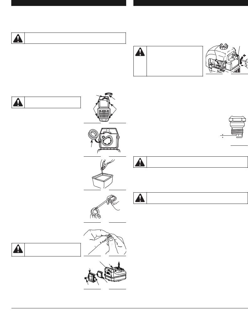
Cleaning the Air Filter
Clean and re-oil the air filter every 10 hours of operation. It is an important item to maintain. Failure to maintain your air filter properly can result in poor performance or can cause permanent damage to your engine.
1.Remove air filter/muffler cover. Refer to Removing the Air
Filter/Muffler Cover. |
Air Filter |
2.Turn cover over and look inside to locate the air filter. Remove the air filter from inside the air filter/muffler cover (Fig. 22).
3.Wash the filter in detergent and water (Fig. 23). Rinse the filter thoroughly. Squeeze out excess water. Allow it to dry completely.
4.Apply enough clean SAE 30 oil to lightly coat the filter (Fig. 24).
5.Squeeze the filter to spread and remove excess oil (Fig. 25).
6.Replace the air filter inside the air filter/muffler cover (Fig. 22).
NOTE: Operating the unit without the air filter and air filter/muffler cover assembly will VOID the warranty.
Inside Muffler Cover
Fig. 22
Reinstalling the Air Filter/Muffler Cover
1. Place the air filter/muffler cover over the back of the
carburetor and muffler. Align the screw holes.
Fig. 23
NOTE: The choke lever must be in Position 2 (Fig. 21) to install the air filter/muffler cover.
2.Insert the four (4) screws into the holes in the air filter/muffler cover (Fig. 21) and tighten.
Do not over tighten.
SPARK ARRESTOR MAINTENANCE
NOTE: The exhaust can only flow in one direction: AWAY from the engine. Pay close attention when
disassembling the muffler so you can put it back together correctly. Failure to do so will damage the
unit and may cause serious personal injury.
Fig. 24
1. Remove air filter/muffler cover. Refer to Removing the Air Filter/Muffler Cover.
2. Locate the muffler, but do not remove it. Find the two (2) screws on the bottom of the muffler (Fig. 26). These two screws hold the Spark Arrestor Hood Assembly and the spark arrestor screen to the bottom of the muffler. Remove the two (2) screws using either a torx #20 or flat blade screwdriver.
WARNING: If the spark arrestor hood and spark arrestor screen are not tightened securely,
they could fall off causing damage to the unit
and possible serious personal injury.
Fig. 25
3. |
Using a small flat blade screwdriver, carefully pry up the spark |
Spark |
Slots |
Engine |
|
arrestor screen from the recessed hole, taking care to notice that |
|
Muffler |
|
|
the “raised” part of the spark arrestor screen is inside the recessed |
Arrestor |
|
|
|
Hood |
|
|
|
|
hole. Remove the spark arrestor screen from the muffler. |
|
|
|
|
|
|
|
|
4. |
Clean the spark arrestor screen with a wire brush. Replace |
|
|
|
|
it if it is damaged, or if you are unable to clean it thoroughly. |
|
|
|
5. |
Reinstall the spark arrestor screen by putting the “raised” |
|
|
|
|
portion of the screen inside the recessed hole of the muffler. |
|
|
|
|
Make sure that the spark arrestor screen fits flat against the |
Screw |
|
Spark Arrestor |
|
muffler. |
Tabs |
Screen |
|
6. |
Place the spark arrestor plate on top of the spark arrestor |
|
Fig. 26 |
|
with the “raised” side up and the opening facing towards the engine (Fig. 26).
7.Place the spark arrestor hood on top of the spark arrestor plate with the “raised” side up and the opening facing AWAY from the engine (Fig. 26). Verify that the exhaust will be directed AWAY from the engine.
8.Replace the two screws you removed in Step 2 and tighten them securely.
9.Reinstall the air filter/muffler cover.
MAINTENANCE AND REPAIR INSTRUCTIONS
CARBURETOR ADJUSTMENT
The idle speed of the engine is adjustable through the air filter/muffler cover (Fig. 27).
NOTE: Careless adjustments can seriously damage your unit. An authorized service dealer should make carburetor adjustments.
Check Fuel Mixture
Old and/or improperly mixed fuel is usually the reason for improper unit performance. Drain and refill the tank with fresh, properly-mixed fuel prior to making any adjustments. Refer to Oil and Fuel Information.
Clean Air Filter
The condition of the air filter is important to the operation of the unit. A dirty air filter will restrict air flow and change the air/fuel mixture. This is often mistaken for an out of adjustment carburetor. Check the condition of the air filter before adjusting the idle speed screw. Refer to Air Filter Maintenance.
Adjust Idle Speed Screw
WARNING: This unit will need to be running during idle speed adjustment. Wear protective clothing and observe all safety instructions to prevent serious personal injury.
Also, DO NOT set unit on any surface except a clean, hard area while starting or performing any adjustments. Debris such as gravel, sand, dust, grass, etc. could be picked up by the air intake and thrown out by the discharge opening, damaging unit, property, or causing serious injury to bystanders or operator.
Idle Speed Screw
Fig. 27
If after checking the fuel mixture and cleaning the air filter the engine still will not idle, adjust the idle speed adjuster as follows.
1.Start the engine and let it run at the fast position for a minute to warm up.
2.Set the blower/vacuum mode Quickshift® lever to the up position (Blower Mode). Refer to Operating as a Blower.
NOTE: Setting the lever to the blower mode prevents the vacuum bag from filling up while starting or running the unit.
3.Move the throttle control and let the engine idle. If the engine stops, insert a small phillips screwdriver into the hole in the air filter/muffler cover (Fig. 27). Turn the idle speed adjuster in, clockwise, 1/8 of a turn at a time (as needed) until the engine idles smoothly.
4.If the unit appears to be idling too fast, turn the idle speed adjuster counterclockwise 1/8 of a turn at a time (as needed), to reduce idle speed.
Checking the fuel mixture, cleaning the air filter, and adjusting the idle speed should solve most engine problems. If not and all of the following are true: 
• the engine will not idle
• the engine hesitates or stalls on acceleration
• there is a loss of engine power Have the carburetor adjusted by an authorized service dealer.
REPLACING THE SPARK PLUG
0.025 in.
Use spark plug P/N 791-610311B, or equivalent. The correct air (0.635 mm)  gap is 0.025 inch (0.635 mm). Remove the plug after every 25
hours of operation and check its condition.
1. |
Stop the engine and allow it to cool. Grasp the plug wire |
|
Fig. 28 |
|
|||
|
firmly and pull it from the spark plug. |
|
|
|
|
|
2.Clean around the spark plug. Remove the spark plug from the cylinder head by turning a 5/8-inch socket counterclockwise.
WARNING: Do not sand blast, scrape or clean electrodes. Grit in the engine could damage the cylinder.
3.Replace a cracked, fouled or dirty spark plug. Set the air gap at 0.025 inch (0.635 mm) using a feeler gauge (Fig. 28).
4.Install a correctly-gapped spark plug in the cylinder head. Tighten by turning the 5/8-inch socket clockwise until snug.
If using a torque wrench torque to: 110-120 in.•lb. (12.3-13.5 N•m)
Do not over tighten.
CLEANING THE UNIT
WARNING: To avoid serious personal injury, always turn your trimmer off and allow it to cool before you clean or service it.
Use a small brush to clean off the outside of the unit. Do not use strong detergents. Household cleaners that contain aromatic oils such as pine and lemon, and solvents such as kerosene, can damage plastic housing or handle. Wipe off any moisture with a soft cloth.
CLEANING THE VACUUM BAG
1.Empty the bag after each use to avoid deterioration and obstructing air flow, which will reduce the performance of the vacuum.
2.Wearing eye protection and a dust mask, clean the bag as needed. Turn the bag inside out after initial emptying and vigorously shake out dust and debris.
3.Wash the bag once a year or more often if needed:
a.Remove the vacuum bag.
b.Turn bag inside out.
c.Hang it up.
d.Hose it down thoroughly.
e.Hang to dry.
f.Turn bag right-side out and reinstall.
STORAGE
•Never store a fueled unit where fumes may reach an open flame or spark.
•Allow the engine to cool before storing.
•Store the unit locked up to prevent unauthorized use or damage.
•Store the unit in a dry, well-ventilated area.
•Store the unit out of the reach of children.
6

MAINTENANCE AND REPAIR INSTRUCTIONS
LONG TERM STORAGE
If you plan on storing the unit for an extended time, use the following storage procedure:
1.Drain all fuel from the fuel tank into a container with the same 2-cycle fuel mixture. Do not use fuel that has been stored for more than 60 days. Dispose of the old fuel/oil mix in accordance to Federal, State and Local regulations.
2.Start the engine and allow it to run until it stalls. This ensures that all fuel has been drained from the carburetor.
3.Allow the engine to cool. Remove the spark plug and put 1 oz. (30 ml) of any high quality motor oil or 2-cycle oil into the cylinder. Pull the starter rope slowly to distribute the oil. Reinstall the spark plug.
NOTE: Remove the spark plug and drain all of the oil from the cylinder before attempting to start the unit after storage.
4.Thoroughly clean the unit and inspect it for any loose or damaged parts. Repair or replace damaged parts and tighten loose screws, nuts or bolts. The unit is ready for storage.
TRANSPORTING
•Allow the engine to cool before transporting.
•Drain fuel from unit.
•Tighten fuel cap before transporting.
•Secure the unit while transporting.
TROUBLESHOOTING
ENGINE WILL NOT START |
|
|
CAUSE |
ACTION |
|
|
|
|
Throttle lever is in the incorrect position |
Refer to the Starting/Stopping instructions |
|
Empty fuel tank |
Fill fuel tank with properly mixed fuel |
|
|
|
|
Primer bulb wasn't pressed enough |
Press primer bulb fully and slowly 10 times |
|
Engine is flooded |
Move the choke lever to Position 3, flip Throttle lever |
|
to FAST and pull the starter rope |
||
|
||
|
|
|
Old or improperly mixed fuel |
Drain gas tank and add fresh fuel mixture |
|
Fouled spark plug |
Replace or clean the spark plug |
|
|
|
|
Plugged spark arrestor |
Clean or replace spark arrestor |
|
|
|
|
ENGINE WILL NOT IDLE |
|
|
CAUSE |
ACTION |
|
|
|
|
Air filter is plugged |
Replace or clean the air filter |
|
Old or improperly mixed fuel |
Drain gas tank and add fresh fuel mixture |
|
|
|
|
Improper carburetor adjustment |
Adjust according to the Carburetor Adjustments |
|
section |
||
|
||
|
|
|
ENGINE WILL NOT ACCELERATE |
|
|
CAUSE |
ACTION |
|
|
|
|
Old or improperly mixed fuel |
Drain gas tank and add fresh fuel mixture |
|
Improper carburetor adjustment |
Take to an authorized service dealer for an |
|
adjustment |
||
|
||
|
|
|
Dirty air filter |
Clean or replace the air filter |
|
Plugged spark arrestor |
Clean or replace spark arrestor |
|
|
|
|
ENGINE LACKS POWER OR STALLS WHEN CUTTING |
||
CAUSE |
ACTION |
|
|
|
|
Old or improperly mixed fuel |
Drain gas tank and add fresh fuel mixture |
|
Improper carburetor adjustment |
Take to an authorized service dealer for an |
|
adjustment |
||
|
||
|
|
|
Fouled spark plug |
Replace or clean the spark plug |
|
Plugged spark arrestor |
Clean or replace spark arrestor |
|
|
|
|
UNIT WILL NOT BLOW OR VACUUM |
|
|
CAUSE |
ACTION |
|
|
|
|
Bag is full |
Empty bag. See Empty the Vacuum Bag |
|
Damaged impeller |
Take unite to an authorized service dealer |
|
|
|
|
Blocked Tube |
Remove the Blower/ Vacuum Tube to remove any |
|
debris |
||
|
||
|
|
|
If further assistance is required, contact your authorized service dealer.
SPECIFICATIONS
ENGINE*
Engine Type . . . . . . . . . . . . . . . . . . . . . . . . . . . . . . . . . . . . . . . . . . . . . . . . . . . . . . . . . Air-Cooled, 2-Cycle Displacement. . . . . . . . . . . . . . . . . . . . . . . . . . . . . . . . . . . . . . . . . . . . . . . . . . . . . . . . . . . 31 cc (1.9 cu. in) Operating RPM . . . . . . . . . . . . . . . . . . . . . . . . . . . . . . . . . . . . . . . . . . . . . . . . . . . . . . . . . 6,800-9,200 rpm Idle Speed RPM . . . . . . . . . . . . . . . . . . . . . . . . . . . . . . . . . . . . . . . . . . . . . . . . . . . . . . . . 3,200-4,200 rpm Ignition Type . . . . . . . . . . . . . . . . . . . . . . . . . . . . . . . . . . . . . . . . . . . . . . . . . . . . . . . . . . . . . . . . . Electronic On/Off Stop Control . . . . . . . . . . . . . . . . . . . . . . . . . . . . . . . . . . . . . . . . . . . . . . . . . . . . . . . Rocker Switch Spark Plug Gap . . . . . . . . . . . . . . . . . . . . . . . . . . . . . . . . . . . . . . . . . . . . . . . . . . . . 0.025 inch (0.635 mm) Lubrication. . . . . . . . . . . . . . . . . . . . . . . . . . . . . . . . . . . . . . . . . . . . . . . . . . . . . . . . . . . . . . Fuel/Oil Mixture Fuel/Oil Ratio . . . . . . . . . . . . . . . . . . . . . . . . . . . . . . . . . . . . . . . . . . . . . . . . . . . . . . . . . . . . . . . . . . . . 40:1 Carburetor. . . . . . . . . . . . . . . . . . . . . . . . . . . . . . . . . . . . . . . . . . . . . . . . . . . . . . . . Diaphragm, All-Position Starter. . . . . . . . . . . . . . . . . . . . . . . . . . . . . . . . . . . . . . . . . . . . . . . . . . . . . . . . . . . . . . . . . . . . Auto Rewind Muffler. . . . . . . . . . . . . . . . . . . . . . . . . . . . . . . . . . . . . . . . . . . . . . . . . . . . . . . . . . . . . . . Baffled with Guard Fuel Tank Capacity . . . . . . . . . . . . . . . . . . . . . . . . . . . . . . . . . . . . . . . . . . . . . . . . . . . . . 13 ounces (384 ml)
BLOWER/ VAUUM*
Throttle Control. . . . . . . . . . . . . . . . . . . . . . . . . . . . . . . . . . . . . . . . . . . . . . . . . . . . . . . . . . Finger-Tip Lever Blower Velocity . . . . . . . . . . . . . . . . . . . . . . . . . . . . . . . . . . . . . . . . . . . . . . . . . . . up to 180 mph (290 kmh) Blower Air Output . . . . . . . . . . . . . . . . . . . . . . . . . . . . . . . . . . . . . . . . . . . . . . . . up to 425 cfm (12.1 cmm) Mulching Ratio. . . . . . . . . . . . . . . . . . . . . . . . . . . . . . . . . . . . . . . . . . . . . . . . . . . . . . . . . . . . . . . . up to 10:1 Vacuum Bag Capacity . . . . . . . . . . . . . . . . . . . . . . . . . . . . . . . . . . . . . . . . . . . . . 0.75 bushels (26.4 Liters) Shoulder Harness. . . . . . . . . . . . . . . . . . . . . . . . . . . . . . . . . . . . . Optional Accessory (Single Quick-Snap) Approximate Weight (no fuel, with blower/vacuum tube and empty vacuum bag) . . . . . . . . . .13 lb. (6 kg)
*All specifications are based on the latest product information available at the time of printing. We reserve the right to make changes at any time without notice.
7

CALIFORNIA / EPA EMISSION CONTROL WARRANTY STATEMENT
Your Warranty Rights and Obligations
The California Air Resources Board, the Environmental Protection Agency, and Troy-Bilt LLC ( TROY-BILT) are pleased to explain the emission control system warranty on your 2007 and later small off-road engine. In California and the 49 states, new small off-road engines must be designed, built and equipped to meet the state’s stringent anti-smog standards. TROY-BILT must warrant the emission control system on your small offroad engine for the periods of time listed below provided there has been no abuse, neglect or improper maintenance of your small off-road engine.
Your emission control system may include parts such as the carburetor or fuel-injection system, the ignition system, and catalytic converter. Also included may be hoses, belts, connectors and other emission-related assemblies.
Where a warrantable condition exists, TROY-BILT will repair your small off-road engine at no cost to you including diagnosis, parts and labor.
The 2007 and later small off-road engines are warranted for two years. If any emission-related part on your engine is defective, the part will be repaired or replaced by TROY-BILT.
Owners Warranty Responsibilities
As the small off-road engine owner, you are responsible for the performance of the required maintenance listed in your operator’s manual. TROY-BILT recommends that you retain all receipts covering maintenance on your small off-road engine, but TROY-BILT cannot deny warranty solely for the lack of receipts or for your failure to ensure the performance of all scheduled maintenance.
•As the small off-road engine owner, you should however be aware that TROY-BILT may deny you warranty coverage if your small off-road engine or a part has failed due to abuse, neglect, improper maintenance or unapproved modifications.
•You are responsible for presenting your small off-road engine to a TROY-BILT Authorized Service Center as soon as a problem exists. The warranty repairs should be completed in a reasonable amount of time, not to exceed 30 days.
If you have any questions regarding your warranty rights and responsibilities, you should call 1-800-828-5500.
Manufacturer’s Warranty Coverage
•The warranty period begins on the date the engine or equipment is delivered to the retail purchaser.
•The manufacturer warrants to the initial owner and each subsequent purchaser, that the engine is free from defects in material and workmanship which cause the failure of a warranted part for a period of two years.
•Repair or replacement of warranted part will be performed at no charge to the owner at an Authorized TROY-BILT Service Center. For the nearest location please contact TROY-BILT at: 1-800-828-5500.
•Any warranted part which is not scheduled for replacement, as required maintenance or which is scheduled for only for regular inspection to the effect of “Repair or Replace as Necessary” is warranted for the warranty period. Any warranted part which is scheduled for replacement as required maintenance will be warranted for the period of time up to the first scheduled replacement point for that part.
•The owner will not be charged for diagnostic labor which leads to the determination that a warranted part is defective, if the diagnostic work is performed at an Authorized TROY-BILT Service Center.
•The manufacturer is liable for damages to other engine components caused by the failure of a warranted part still under warranty.
•Failures caused by abuse, neglect or improper maintenance are not covered under warranty.
•The use of add-on or modified parts can be grounds for disallowing a warranty claim. The manufacturer is not liable to cover failures of warranted parts caused by the use of add-on or modified parts.
•In order to file a claim, go to your nearest Authorized TROY-BILT Service Center. Warranty services or repairs will be provided at all Authorized TROY-BILT Service Centers.
•Any manufacturer approved replacement part may be used in the performance of any warranty maintenance or repair of emission related parts and will be provided without charge to the owner. Any replacement part that is equivalent in performance or durability may be used in non-warranty maintenance or repair and will not reduce the warranty obligations of the manufacturer.
Emission Warranty Parts List:
The following components are included in the emission-related warranty of the engine: air filter, carburetor, primer, fuel lines, fuel pick up/ fuel filter, ignition module, spark plug, and muffler. Valves and Cam are additionally included if your engine is a 4-Stroke Model.
CALIFORNIA EVAPORATIVE EMISSION CONTROL WARRANTY STATEMENT
Your Warranty Rights and Obligations
The California Air Resources Board and Troy-Bilt LLC ( TROY-BILT) is pleased to explain the evaporative emission control system’s warranty on your 2007 model year and later small off-road (equipment type) engine. In California, new equipment that use small off-engines must be designed, built, and equipped to meet the State’s stringent anti-smog standards TROY-BILT must warrant the evaporative emission control system on your small off-road Lawn & Garden engine for the period listed below provided there has been no abuse, neglect or improper maintenance of your equipment.
Your evaporative emission control system may include parts such as: carburetors, fuel tanks, fuel lines, fuel caps, valves, canisters, filters, vapor hoses, clamps, connectors, and other associated components. For engines less than or equal to 80 cc, only the fuel tank is subject to the evaporative emission control warranty requirements of this section. The displacement of your small off road engine is less than 80 cc.
Manufacturer’s Warranty Coverage
This evaporative emission control system is warranted for two years. If any evaporative emission-related part on your equipment is defective, the part will be repaired or replaced by TROY-BILT.
Owner’s Warranty Responsibilities
•As the small off-road Lawn & Garden engine owner, you are responsible for performance of the required maintenance listed in your owner’s manual. TROY-BILT recommends that you retain all receipts covering maintenance on your Lawn & Garden Engine but TROY-BILT cannot deny warranty solely for the lack of receipts.
•As the small off-road Lawn & Garden engine owner, you should however be aware that the TROY-BILT may deny you warranty coverage if your fuel tank has failed due to abuse, neglect, or improper maintenance or unapproved modifications.
•You are responsible for presenting your Lawn & Garden fuel tank to TROY-BILT distribution center or service center as soon as the problem exists. The warranty repairs should be completed in a reasonable amount of time, not to exceed 30 days. If you have a question regarding your warranty coverage, you should contact TROY-BILT at 1-800-828-5500.
Defects Warranty Requirements
(a)The warranty period begins on the date the engine or equipment is delivered to an ultimate purchaser.
(b)General Evaporative Emissions Warranty Coverage. The fuel tank must be warranted to the ultimate purchaser and any subsequent owner that the evaporative emission control system when installed was:
(1)Designed, built, and equipped so as to conform with all applicable regulations; and
(2)Free from defects in materials and workmanship that causes the failure of a warranted part for a period of two years.
(c)The warranty on evaporative emissions-related parts will be interpreted as follows:
(1)Any warranted part that is not scheduled for replacement as required maintenance in the written instructions must be warranted for the warranty period defined in subsection (b)(2). If any such part fails during the period of warranty coverage, it must be repaired or replaced by TROY-BILT. Any such part repaired or replaced under the warranty must be warranted for a time not less than the remaining warranty period.
(2)Any warranted part that is scheduled only for regular inspection in the written instructions must be warranted for the warranty period defined in subsection (b)(2). A statement in such written instructions to the effect of “repair or replace as necessary” will not reduce the period of warranty coverage. Any such part repaired or replaced under warranty must be warranted for a time not less than the remaining warranty period.
(3)Any warranted part that is scheduled for replacement as required maintenance in the written instructions must be warranted for the period of time prior to the first scheduled replacement point for that part. If the part fails prior to the first scheduled replacement, the part must be repaired or replaced by the TROY-BILT. Any such part repaired or replaced under warranty must be warranted for a time not less than the remainder of the period prior to the first scheduled replacement point for the part.
(4)Repair or replacement of any warranted part under the warranty provisions of this article must be performed at no charge to the owner at a warranty station.
(5)Not withstanding the provisions of subsection (4) above, warranty services or repairs must be provided at distribution centers that are franchised to service the subject engines or equipment.
(6)The owner must not be charged for diagnostic labor that leads to the determination that a warranted part is in fact defective, provided that such diagnostic work is performed at a warranty station.
(7)Throughout the evaporative emission control system’s warranty period set out in subsection (b)(2), TROY-BILT must maintain a supply of warranted parts sufficient to meet the expected demand for such parts.
(8)Manufacturer approved replacement parts must be used in the performance of any warranty maintenance or repairs and must be provided without charge to the owner. Such use will not reduce the warranty obligations of the manufacturer issuing the warranty.
(9)The use of any add-on or modified parts will be grounds for disallowing a warranty claim made in accordance with this article. The manufacturer issuing the warranty will not be liable under this Article to warrant failures of warranted parts caused by the use of an add-on or modified part.
(10)TROY-BILT shall provide any documents that describe the warranty procedures or policies within five working days of request by the Air Resources Board.
Emission Warranty Parts List
(1)Fuel Tank
Written instructions for the maintenance and use of the evaporative emissions control system by the owner shall be furnished with each new engine or equipment.
8

Manuel de L'utilisateur
Souffleuse Aspirateur Á Pailler à 2-temps
TB310QS
TABLE DES MATIÈRES
Service technique . . . . . . . . . . . . . . . . . . . . . . . . . . . . . . . . . . . . . .9 Consignes de sécurité . . . . . . . . . . . . . . . . . . . . . . . . . . . . . . . . . .10 Familiarisez-vous avec votre appareil . . . . . . . . . . . . . . . . . . . . . .12 Instructions de montage . . . . . . . . . . . . . . . . . . . . . . . . . . . . . . . .12 Informations sur l'huile et le carburant . . . . . . . . . . . . . . . . . . . . .12 Instructions de démarrage et d'arrêt . . . . . . . . . . . . . . . . . . . . . . .13 Mode d'emploi . . . . . . . . . . . . . . . . . . . . . . . . . . . . . . . . . . . . . . .13 Entretien et réparations . . . . . . . . . . . . . . . . . . . . . . . . . . . . . . . . .14 Nettoyage et entreposage . . . . . . . . . . . . . . . . . . . . . . . . . . . . . . .15 Tableau de dépannage . . . . . . . . . . . . . . . . . . . . . . . . . . . . . . . . .15 Caractéristiques . . . . . . . . . . . . . . . . . . . . . . . . . . . . . . . . . . . . . .15 Garantie . . . . . . . . . . . . . . . . . . . . . . . . . . . . . . . . . . . . . . . . . . . . .28 Liste des pièces . . . . . . . . . . . . . . . . . . . . . . . . . . . . . . . . . . . . . .26
Dans un effort de réduire l’impact sur les forets et réduire les émissions de gaz carbonique ainsi que les émissions de gaz à effet de serre, MTD utilise moins de papier en réduisant la taille du texte de ce manuel.
PART NO. 769-03704
CONSERVEZ CES INSTRUCTIONS
Obtenez la liste des concessionnaires agréés appelez le 1-800-828-5500 aux États-Unis ou le 1-800-668-1238 au Canada. Pour de plus amples informations à propos de votre appareil, visitez www.troybilt.com.
Si vous éprouvez des difficultés à assembler ce produit ou si vous avez des questions sur les commandes, l'utilisation ou l'entretien de cet appareil, veuillez contacter le service à la clientèle.
NE RETOURNEZ PAS L'APPAREIL AU DÉTAILLANT CHEZ QUI VOUS L'AVEZ ACHETÉ. TOUT SERVICE SOUS GARANTIE NÉCESSITE UNE PREUVE D'ACHAT.
CE PRODUIT EST COUVERT PAR UN OU PLUSIEURS BREVETS AMÉRICAINS, ET D’AUTRES SONT EN INSTANCE.
Tout entretien effectué sur cet appareil pendant et après la période de garantie doit être fait par un concessionnaire agréé uniquement.
Avant de commencer, trouver la plaque indiquant le modèle de l’appareil. Vous y trouverez le modèle et les numéros de série de votre appareil. Consultez l’exemple de plaque ci-dessous et copiez les informations pour toute référence future.
Copiez le numéro de modèle / pièce mère ici :
Copiez le numéro de série ici :
PARE-ÉTINCELLES
REMARQUE: à l'intention des utilisateurs opérant dans les terres forestières des États-Unis et dans les états de Californie, du Maine, de l'Orégon et de Washington. Toutes les terres forestières des États-Unis et de l'état de Californie (Codes sur les ressources publiques 4442 et 4443), de l'Orégon et de Washington exigent de par la loi que certains moteurs à combustion interne utilisés dans des zones couvertes de taillis ou d'herbe soient équipés d'un pare-étincelles en parfait état de fonctionnement, ou qu'ils soient conçus, équipés et entretenus pour la prévention des incendies. Renseignez-vous auprès des autorités de votre province ou de votre municipalité concernant la réglementation en vigueur. Vous pourriez être passible d'une amende ou être tenu responsable si vous ne respectez pas cette réglementation. Cet appareil est équipé d'un pare-étincelles en usine. Si l'écran pare-étincelles, réf. 753-05709, doit être remplacé, communiquez avec le service technique.
PROPOSITION 65 DE CALIFORNIE
AVERTISSEMENT
LES GAZ D'ÉCHAPPEMENT DU MOTEUR DE CET APPAREIL CONTIENNENT DES PRODUITS CHIMIQUES CONSIDÉRÉS PAR L'ÉTAT DE CALIFORNIE COMME POUVANT CAUSER LE CANCER, DES MALFORMATIONS CONGÉNITALES OU D'AUTRES EFFETS NOCIFS SUR L'APPAREIL DE REPRODUCTION.
Toutes les informations, illustrations et spécifications contenues dans ce manuel tiennent compte des dernières informations techniques disponibles au moment de mettre sous presse. Nous nous réservons le droit d'y apporter des modifications à tout moment, sans préavis.
Copyright© 2008 MTD SOUTHWEST INC., Tous droits réservés.
(1/08)
 Loading...