

Trebor IQ Chemical Heater User Manual

IQ CHEMICAL
HEATER
Operation / Maintenance
Manual
SERIAL NUMBER:
PATENTS: U.S. 5971402, U.S. 6433319, U.S. 6479094B2, U.S. 6544583B2, 01/25/13 – MIQ-B
U.S. 6580061B2, U.S. 6663914, U.S 6674053B2;
ADDITIONAL PATENTS PENDING

CONTENTS
1 INTRODUCTION ........................................................................................................... 3
1.1 INTENDED USE AND AUDIENCE ..................................................................... 4
1.2 HEATER SIZING ................................................................................................ 4
2 SAFETY ........................................................................................................................ 5
2.1 SAFETY PRECAUTIONS ................................................................................... 5
2.1.a General Safety ....................................................................................... 5
2.2 SAFETY MESSAGE CONVENTIONS ............................................................... 5
2.2.a Caution .................................................................................................. 5
2.2.b Warning ................................................................................................. 6
2.2.c Danger ................................................................................................... 6
2.3 HEATER INTERLOCKS ..................................................................................... 6
2.3.a Leak Sensor........................................................................................... 6
2.3.b Element Over-Temperature Protection ................................................. 7
2.3.c Liquid Over-Temperature Protection ..................................................... 7
2.3.d Internal Over-Temperature Protection ................................................... 8
2.3.e Liquid Level Sensor Interlock ................................................................ 8
3 INSTALLATION ............................................................................................................ 9
3.1 UTILITY REQUIREMENTS .............................................................................. 10
3.2 UNPACKING .................................................................................................... 10
3.3 ORIENTATION ................................................................................................. 10
3.4 FLUID CONNECTIONS .................................................................................... 10
3.4.a Inlet & Outlet ........................................................................................ 10
3.4.b Liquid Drain .......................................................................................... 10
3.5 ELECTRICAL CONNECTIONS ........................................................................ 11
4 OPERATION ............................................................................................................... 12
4.1 GENERAL ......................................................................................................... 12
4.2 LIQUID START-UP ........................................................................................... 12
4.3 TEMPERATURE CONTROL ............................................................................ 13
4.4 SHUT DOWN .................................................................................................... 13
5 MAINTENANCE .......................................................................................................... 14
5.1 SPARE PARTS ................................................................................................. 14
5.2 PREVENTIVE MAINTENANCE SCHEDULE ................................................... 14
5.3 REMOVAL AND REPLACEMENT INSTRUCTIONS ....................................... 14
5.3.a Heater Replacement ............................................................................ 14
5.3.b Heater Decommissioning .................................................................... 14
5.3.c Heater Disposal ................................................................................... 14
6 TROUBLESHOOTING ............................................................................................... 15
6.1 IRREGULAR TEMPERATURE CONTROL ...................................................... 15
6.2 HEATER ELEMENT CHECK ........................................................................... 15
6.3 INTERLOCK SENSORS .................................................................................. 16
7 WIRING SCHEMATIC ................................................................................................ 17
8 OPTIONS .................................................................................................................... 20
8.1 FLUID CONNECTIONS (IQL04V208SB08AAA00): ......................................... 20
8.2 LIQUID LEVEL SENSOR (IQL04V208SB08AAA00): ...................................... 20
8.3 LEAK SENSOR (IQL04V208SB08AAA00): ..................................................... 20
8.4 INTERLOCK TEMPERATURE SENSORS (IQL04V208SB08AAA00): ........... 20
9 WARRANTY AND EXCLUSIONS .............................................................................. 21
10 CONTACT INFORMATION ........................................................................................ 22
10.1 GENERAL CONTACT INFORMATION ............................................................ 22
10.2 TECHNICAL SUPPORT ................................................................................... 22
10.3 REGIONAL REPRESENTATIVES ................................................................... 22
MODEL IQ QUARTZ HEATER OPERATION / MAINTENANCE MANUAL CONTENTS
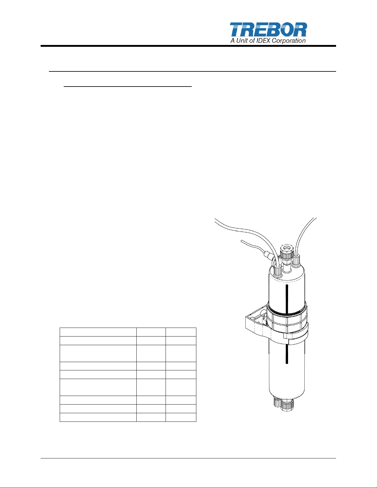
Shown with Optional Capacitive
Fluid Connections and Drain
IQL — Low Temperature
Metric
English
Maximum Pressure
.55 MPa
80 psig
Maximum Chemical
Operating Temperature
100 °C
212 °F
IQH — High Temperature
Maximum Pressure
.31 MPa
45 psig
Maximum Chemical
Operating Temperature
200 °C
392 °F
IQL/IQH
Minimum Pressure
.10 MPa
15 psig
Minimum Flow Rate
2 LPM
.53 GPM
1 INTRODUCTION
IQ Chemical Heater - The Smart Choice!
Trebor’s IQ in-line quartz chemical heater provides the ultra-high purity you demand, with
the reliability you expect.
The IQ’s flow path is smooth, free of particle traps and constructed entirely of GE 214
quartz and PFA, making it compatible with all non-combustible chemistries, except HF &
KOH. The PFA enclosure ensures plenum compatibility and resists corrosion or
discoloration. Most importantly, unlike immersion style resistive heaters your application is
free from metal ion contamination risk if the external thin-film heating element should fail.
Trebor’s patented sealing technology not only protects against liquid leaks, but eliminates
the breakage commonly associated with fragile quartz fluid connections. Plus, there are no
O-rings to service or replace.
Simplicity and flexibility are key elements of the IQ heater. The modular design allows
heaters to be connected in parallel or series. Heaters are available in multiple voltages
and with multiple fluid fitting options to accommodate your heating needs.
Features
Quartz/PFA liquid path
Multiple fluid fitting options
No metal contamination risk
No particle traps
Efficient heat transfer and small thermal
volume for fast response
SEMI S2, S3, and CE compliant
Performance Summary
MODEL IQ QUARTZ HEATER OPERATION / MAINTENANCE MANUAL PAGE 3
Fluid Sensor and Pillar Super 300

1.1 INTENDED USE AND AUDIENCE
The IQ chemical heater is designed to safely heat acids, DI water, and other
noncombustible quartz-compatible liquid solutions up to 200°C. The IQ chemical
heater is not intended for use with combustible or flammable chemistries, such
as solvents, or chemistries such as HF or KOH with accelerated quartz etch
rates.
This manual only covers the Trebor IQ chemical heater and heater accessories
provided by Trebor. The user is responsible for the external control system and
all necessary connections required to safely operate the heater (see Sections 4.3
and 7)
The Trebor IQ chemical heater is not to be used for proposes other than that
which is designed for. The heater and optional components are to be used only
with liquids and parameters stated within this manual. This manual assumes
personnel are familiar with the installation, operation and maintenance
requirements of chemical heaters.
The IQ chemical heater is intended for use by properly trained personnel. Read
and understand this manual prior to installation and/or operation of the heater.
Do not use this equipment until familiar with its operation and safety features.
1.2 HEATER SIZING
Sizing Formula
Required kW = 0.264(Flow)(Temp Delta)
Conversion Calculations:
GPM = LPM/3.8
°C = 5/9(°F - 32)
Heater Sizing Formula Example
Temperature delta per pass = 15 °C
Required kW=0.264(1 GPM)(15 °C) = 3.96 kW
For optimal temperature response and to compensate for overshoot; Trebor
recommends adding 25% excess heating capacity.
3.96 kW(1.25) = 4.95 kW.
Trebor recommends a 6 kW heater for this application.
PAGE 4 MODEL IQ CHEMICAL HEATER OPERATION / MAINTENANCE MANUAL
Caution
Corrosive Chemical
Product may contain
hazardous corrosive
liquids.
Handle with care.
2 SAFETY
2.1 SAFETY PRECAUTIONS
This section provides important information for safe operation of the IQ chemical
heater.
The equipment described in this manual uses hazardous voltage electricity that
can be dangerous. Local policies and procedures for safely operating any Trebor
chemical heater(s) supersede the safety considerations listed below. It is the
responsibility of all personnel to follow such policies and procedures. All safety
guard devices must be in place when equipment is in operation. Operators, setup operators, helpers or installation personnel should not alter, remove or disable
safety devices or equipment.
2.1.a General Safety
There are no serviceable parts inside the heater assembly; never open or
disassemble. Attempting to do so will void the product warranty.
Do not attempt to work on or with hazardous chemicals or electrical
equipment without proper safety training and certification, understand first aid
for electrical shock and hazardous chemicals spills.
Lockout and tag the electrical and chemical systems prior to installation or
replacement. Refer to company safety policies and procedures prior to
installation or replacement.
Always disengage the heater and optional equipment from electrical sources
prior to installation or replacement.
Always refer to company safety policies and procedures for flushing and
decontamination prior to removal.
2.2 SAFETY MESSAGE CONVENTIONS
2.2.a Caution
A Caution message indicates a potentially
hazardous situation, which, if not avoided,
could result in minor or moderate injury. It
may also be used to alert against unsafe
practices. A typical Caution message:
MODEL IQ CHEMICAL HEATER OPERATION / MAINTENANCE MANUAL PAGE 5
Warning
Hazardous Voltage
Voltage or current
hazard sufficient to
cause shock, burn or
death. Disconnect and
lockout power before
servicing.
2.2.b Warning
A Warning message indicates a potentially
hazardous situation that, if not avoided,
could result in serious injury. A typical
example of a Warning message:
2.2.c Danger
A Danger message indicates an imminently hazardous situation that, if
not avoided, will result in death or serious injury. Messages identified by
the word Danger are used sparingly and only for those situations
presenting the most serious hazards
2.3 HEATER INTERLOCKS
2.3.a Leak Sensor
The Trebor IQ chemical heater is supplied with a 24Vdc conductive liquid
leak sensor. Note, two modes of operation are available – NPN (normally
open) and PNP (normally closed).
An integrated magnetic reed switch allows a non-intrusive method for
verification of sensor operation. Pass a magnet next to the area near the
heater bottom, labeled “LEAK SENSOR TEST” to engage the reed switch
and alarm the leak sensor, see Figure 2-1. See Section 7 for wiring
instructions.
PAGE 6 MODEL IQ CHEMICAL HEATER OPERATION / MAINTENANCE MANUAL
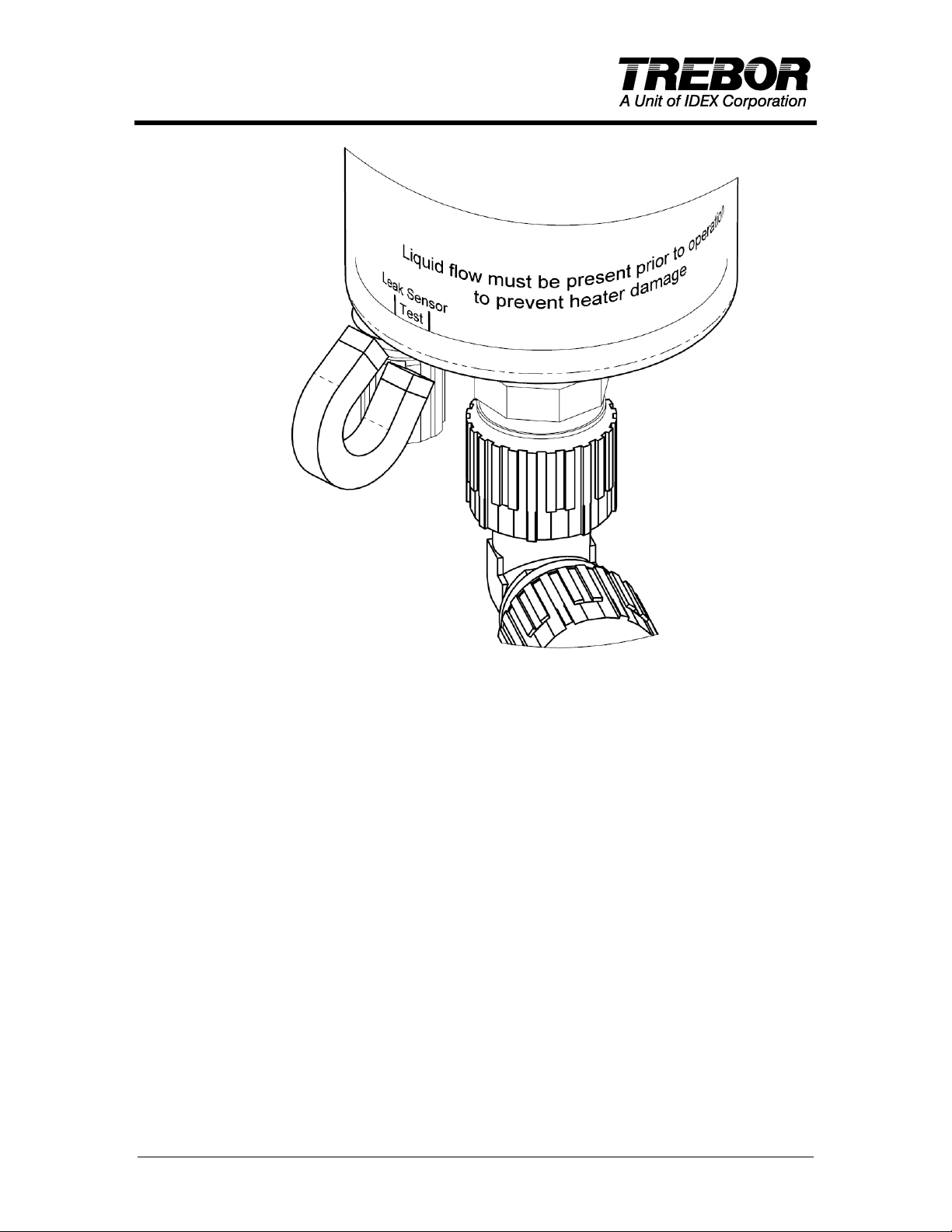
Figure 2-1
Note: The heater has no provision for monitoring or controlling flow rates
or provisions to turn off flow to the heater during a leak alarm. It is
recommended that the user incorporate a separate interlock to isolate
flow and power from the heater in the event of an alarm.
2.3.b Element Over-Temperature Protection
The Trebor IQ chemical heater is supplied with a temperature sensor(s)
located on the heater element. The element temperature sensor(s) must
be used with an interlock to ensure the element temperature does not
exceed 250°C. Note, two types of sensors are available – thermocouple
and RTD. See Section 7 for wiring instructions.
2.3.c Liquid Over-Temperature Protection
The maximum liquid temperature (T
element temperature (Te°C), heater power rating (P - i.e. 3-kW, 4-kW, 6kW, etc.) and duty cycle (duty %). Te = T
Example 1: Given a maximum allowable liquid temperature of 140°C, a
heater rated at 6 kW and a 100% duty cycle, the maximum
element temperature limit is:
°C) can be estimated from the
max
max
+ P * duty * 16.1
Te = 140°C + (6)*(1.00)*(16.1)
MODEL IQ CHEMICAL HEATER OPERATION / MAINTENANCE MANUAL PAGE 7
 Loading...