

Page 1

Phone: 800-669-1303 or 801-561-0303
Fax: 801-255-2312
e-mail: [email protected]
PURUS CP
Operation / Maintenance
Manual
SERIAL NUMBER (located on top of product):
08/29/12– MPCP-A
Page 2

CONTENTS
1 INTRODUCTION .......................................................................................................... 3
1.1 INTENDED USE AND AUDIENCE .................................................................... 4
2 SAFTEY ........................................................................................................................ 5
2.1 SAFETY PRECAUTIONS ................................................................................... 5
2.1.a General Safety ....................................................................................... 5
3 INSTALLATION ............................................................................................................ 6
3.1 UTILITIES / HOOK-UP ....................................................................................... 7
3.2 UNPACKING ...................................................................................................... 7
3.3 ORIENTATION ................................................................................................... 7
3.4 FLUID CONNECTIONS ...................................................................................... 7
4 OPERATION ................................................................................................................. 8
4.1 PRINCIPALS OF OPERATION .......................................................................... 8
4.2 START UP .......................................................................................................... 8
4.3 CONTOLLER ...................................................................................................... 9
4.4 PERFORMANCE CHARTS ................................................................................ 9
5 INSPECTION AND MAINTENANCE ......................................................................... 11
5.1 MAINTENANCE ............................................................................................... 11
5.2 MATERIALS LIST ............................................................................................. 11
5.2.a Wetted Materials .................................................................................. 11
5.2.b Non-wetted Materials ........................................................................... 11
6 PC15CP (OPTIONAL) INSTALLATION .................................................................... 12
6.1 PC15CP OVERVIEW ....................................................................................... 12
6.2 PC15CP INSTALLATION ................................................................................. 12
6.3 PC15CP UTILITIES / HOOK-UP ...................................................................... 13
6.4 PC15CP CONTROLLER OPERATION ............................................................ 14
6.4.a Turning Pump On and Off ................................................................... 14
7 TROUBLESHOOTING ............................................................................................... 15
7.1 PUMP ............................................................................................................... 15
8 WARRANTY AND EXCLUSIONS .............................................................................. 16
9 CONTACT INFORMATION ........................................................................................ 17
9.1 GENERAL CONTACT INFORMATION ............................................................ 17
9.2 TECHNICAL SUPPORT ................................................................................... 17
9.3 REGIONAL REPRESENTATIVES ................................................................... 17
PURUS CP PUMP OPERATION / MAINTENANCE MANUAL CONTENTS
Page 3
1 INTRODUCTION
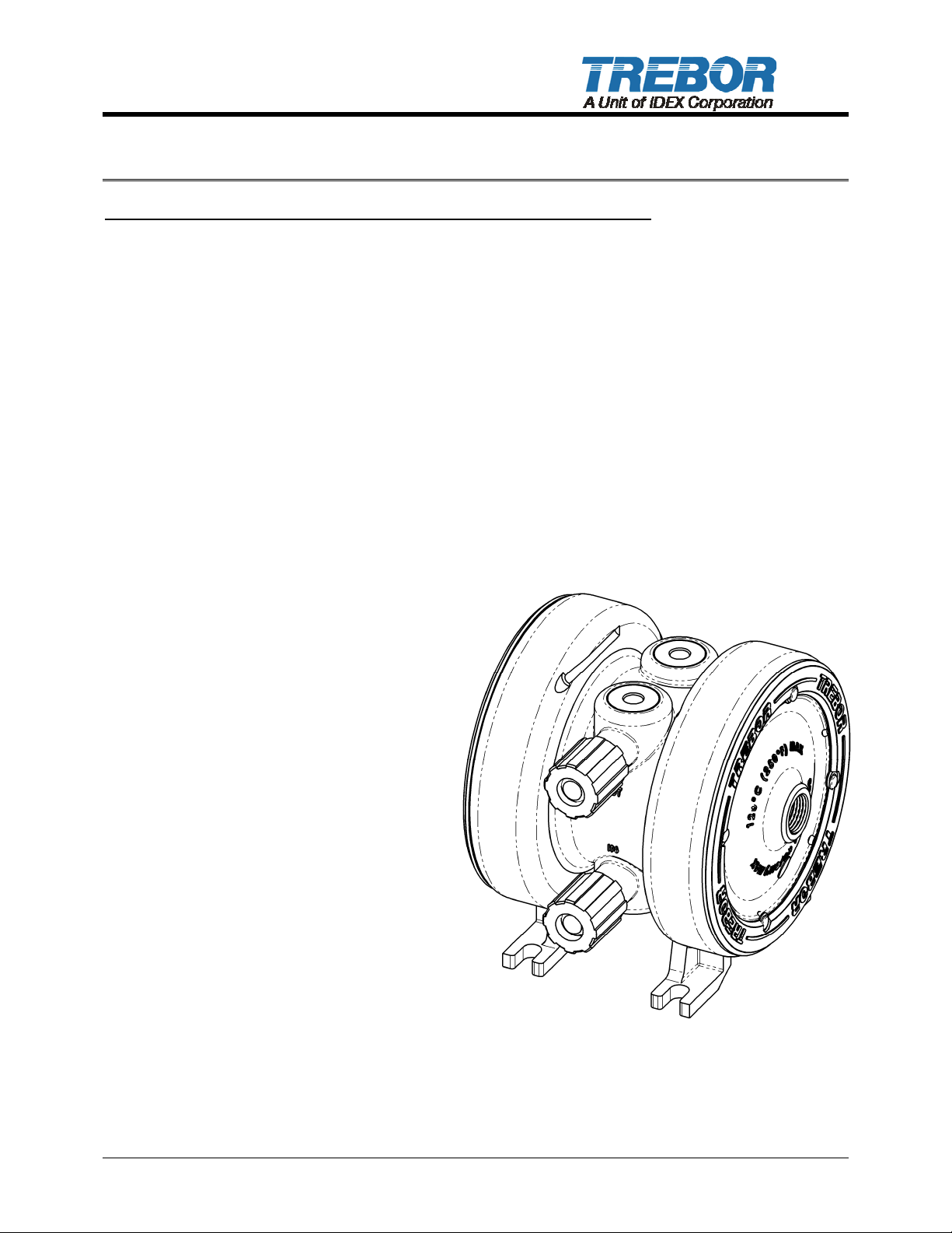
Purus CP – A Revolutionary PFA High-Purity, Low-Pulsation Pump!
TREBOR’S Purus CP diaphragm pump offers a unique solution to critical applications requiring
stable flow and low pulsation. With a revolutionary injection molded PFA design, Trebor has
created an ultrapure pump utilizing proven components with minimal parts. This manufacturing
approach has created a reliable, leak proof, disposable pump that costs less than most
competitors’ rebuild kits; while providing the utmost in purity and performance. The Purus CP is
constructed entirely of PFA and PTFE, and includes no elastomers or metal parts for maximum
purity and chemical compatibility.
Purus CP pumps are externally controlled and when combined with the Trebor PC15 Pump
Controller can minimize pulsation to within 3% peak to peak.
Product Benefits:
Maintains constant flow within 3% or less at flows from 0-6 lpm.
Longer stroke for excellent suction lift and priming capability.
Operating life exceeding 100 million cycles (most applications).
100% PFA/PTFE wetted construction for
the ultimate chemical compatibility and
process purity.
No elastomer seals or gaskets to break
down or replace.
No metal parts to corrode or
contaminate process.
No maintenance.
Compact size.
Air operated.
Handles chemical temperatures up to
120°C.
FM4910 compliant.
Cleaned, assembled, and packaged in
Class 1000 clean room.
PURUS CP PUMP OPERATION / MAINTENANCE MANUAL PAGE 3
Page 4

1.1 INTENDED USE AND AUDIENCE
The Purus CP pump is designed to safely pump liquids up to 120°C.
This manual only covers the Trebor Purus CP pump and pump accessories provided by
Trebor.
The Purus CP pump is not to be used for proposes other than that which it is designed for.
The pump and optional components are to be used only with liquids and parameters
stated within this manual. This manual assumes personnel are familiar with the
installation, operation and maintenance requirements of chemical pumps.
The Purus CP pump is intended for use by properly trained personnel. Read and
understand this manual prior to installation and/or operation of the pump or pump
controller. Do not use this equipment until familiar with its operation and features.
PAGE 4 PURUS CP PUMP OPERATION / MAINTENANCE MANUAL
Page 5
2 SAFTEY
2.1 SAFETY PRECAUTIONS
This section provides important information for safe operation of the Purus CP pump.
The equipment described in this manual can be used to pump hazardous chemicals that
can be dangerous. Local policies and procedures for safely operating any Trebor Purus
CP pump(s) supersede the safety considerations listed below. It is the responsibility of all
personnel to follow such policies and procedures. All safety guard devices must be in
place when equipment is in operation. Operators, set-up operators, helpers or installation
personnel should not alter, remove or disable safety devices or equipment.
2.1.a General Safety
There are no serviceable parts inside the pump; never open or disassemble.
Attempting to do so will render the pump inoperable and void the product warranty.
Do not attempt to work on or with hazardous chemicals or electrical equipment without
proper safety training and certification, understand first aid for electrical shock and
hazardous chemicals spills.
Lockout and tag the electrical and chemical systems prior to installation or
replacement. Refer to company safety policies and procedures prior to installation or
replacement.
Always disengage the pump and optional equipment from electrical sources prior to
installation or replacement.
Always refer to company safety policies and procedures for flushing and
decontamination prior to removal.
CAUTION: When handling potentially dangerous fluids under pressure, the pump
and its fittings should be placed in an enclosure away from operators.
PURUS CP PUMP OPERATION / MAINTENANCE MANUAL PAGE 5
Page 6
3 INSTALLATION
Ensure all system interlock and safety devices are functional prior to operation (refer to
Section 2, Safety Requirements). Before starting the system, it is important to read and
understand Section 4, Operation. Only trained, qualified, authorized personnel should
operate this pump.
9.2
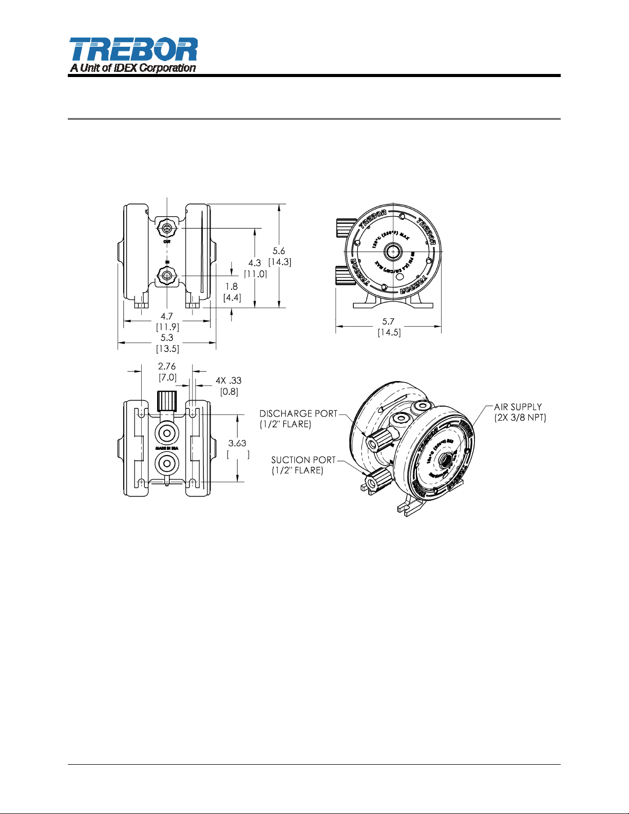
Figure 3-1: Dimensions (in / [cm])
PAGE 6 PURUS CP PUMP OPERATION / MAINTENANCE MANUAL
Page 7

3.1 UTILITIES / HOOK-UP
Utility Pump
Air Inlet:
Air Supply:
Fluid Ports:
Pump Weight:
3.2 UNPACKING
After unpacking, the pump should be checked for any damage that may have occurred
during shipment. Damage should be reported to the carrier immediately.
The following items should be included within the shipping container:
QTY. DESCRIPTION
1 Purus CP Pump
1 Purus CP Manual
1 Quick Installation Guide (QIG)
NOTE: Although extensive efforts are made to deliver pumps to our customers completely
dry, new pumps may contain residual moisture from their final DI water test.
3/8” FNPT per head.
20-80 PSIG (.14 – .55 MPa), clean dry air or inert gas
1/2” Flare
1/2” Tube Stub (Optional)
1/2” Pillar Super 300 (Optional)
2.2 lbs (1.0 Kg) dry
3.3 ORIENTATION
To maintain self-priming ability and pumping efficiency the pump should be positioned
within 15° from level.
3.4 FLUID CONNECTIONS
Attach the inlet and outlet fluid connections per the fitting manufacturer’s
specifications. Fluid connections are located on the pump side, inlet lower and outlet
upper, see Figure 3-1.
For high-temperature operation, Trebor recommends operating the pump with DI water
for two or more thermal cycles to visually inspect for leaks prior to pumping chemicals.
For maximum flow performance, the following is recommended
o Maximize suction line diameter
o Minimize suction line length
o Minimize suction line restrictions (i.e. valves, fittings)
PURUS CP PUMP OPERATION / MAINTENANCE MANUAL PAGE 7
Page 8
4 OPERATION
4.1 PRINCIPALS OF OPERATION
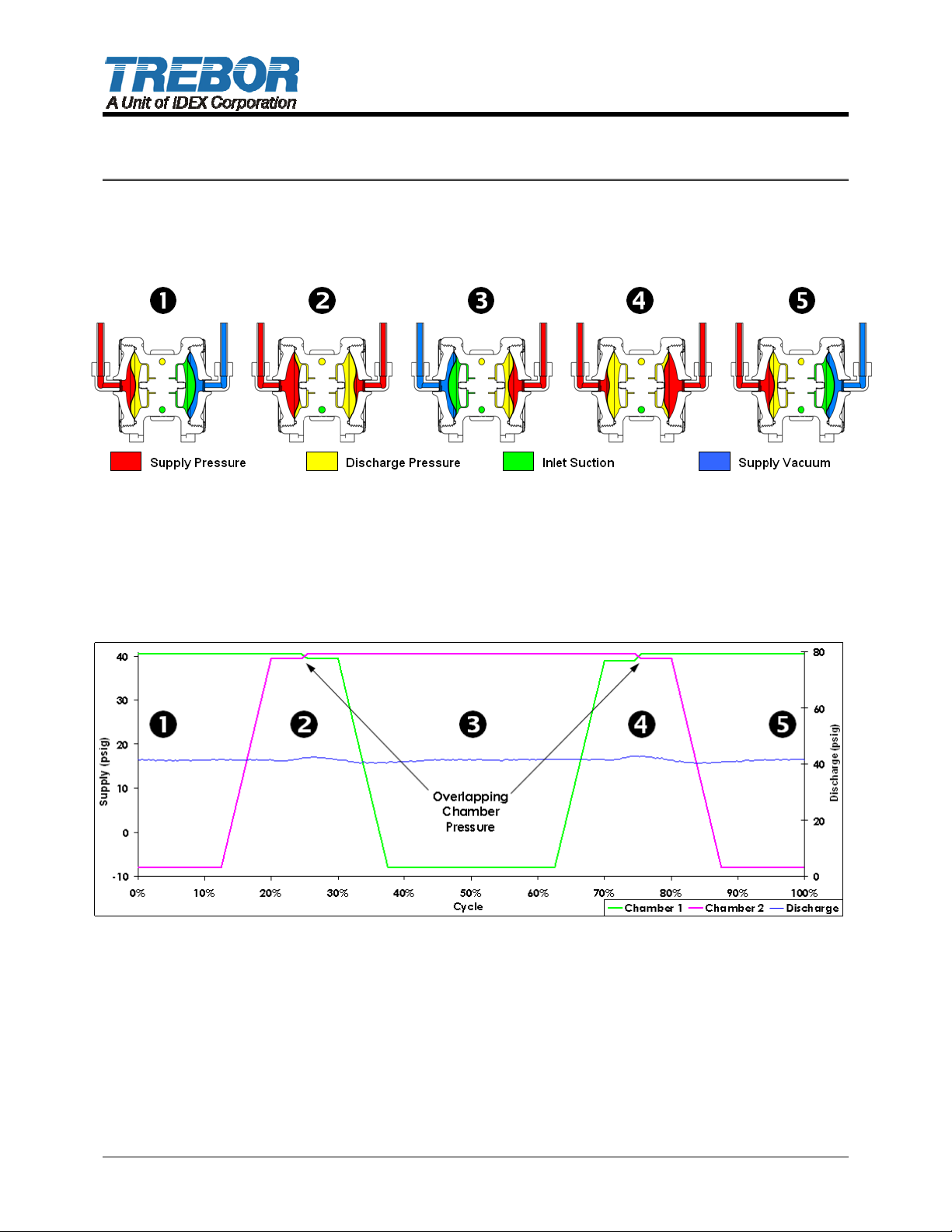
The Purus CP accomplishes near pulseless flow by Cross-Phase operation (refer to
the following step-by-step illustration):
Chamber 1 – pressure / Chamber 2 – vacuum.
Chamber 1 – pressure / Chamber 2 – pressure (crossed-phase).
Chamber 1 – vacuum / Chamber 2 – pressure.
Chamber 1 – pressure / Chamber 2 – pressure (crossed-phase).
Chamber 1 – pressure / Chamber 2 – vacuum.
4.2 START UP
Open the fluid suction (IN) line valve, if necessary
Open the fluid discharge (OUT) line valve, if necessary
Set air pump supply regulator at the desired discharge pressure. Increase pressure to
attain desired outlet pressure, up to the maximum rating (See Section 3.1)
Activate pump controller.
PAGE 8 PURUS CP PUMP OPERATION / MAINTENANCE MANUAL
Page 9
Refer to Troubleshooting Section 7 if pump fails to start or contact Trebor for further
assistance.
ATTENTION: The pump should be operated with clean, dry air or nitrogen. Particulate,
water and oils in the air supply can damage or contaminate the pump air chamber.
NOTE: The Purus CP can be operated dry for extended periods up to 24 continuous
hours.
4.3 CONTOLLER
The Purus CP pump requires an external controller.
o Trebor PC15CP
NOTE: See PC15CP manual for operating instructions, requirements, limitations, and
troubleshooting.
4.4 PERFORMANCE CHARTS
Pumping capacity is a function of air supply pressure and volume, suction head, suction
line restrictions, discharge head, discharge line restriction, and fluid specific gravity and
viscosity.
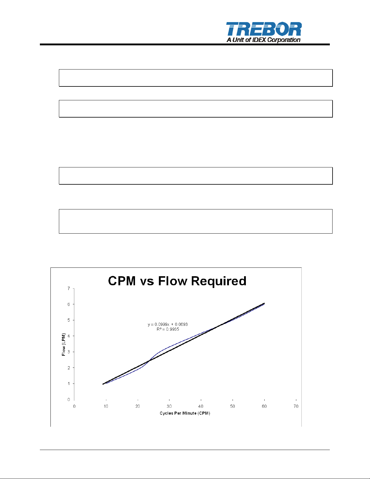
The chart below defines the relationship between the pump controller cycle rate and the
required flow from the Purus CP utilizing the PC15-02 controller.
PURUS CP PUMP OPERATION / MAINTENANCE MANUAL PAGE 9
Page 10
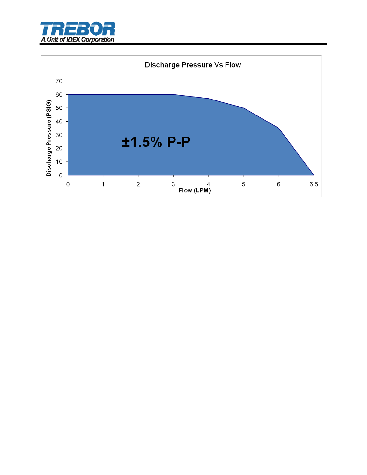
Figure 4-2: Pressure and Flow Capacity Chart
The preceding chart defines a region of operation over which the Purus CP pump may be
operated with a PC15 pump controller with a discharge flow variance of less than +/-1.5%
of nominal value.
PAGE 10 PURUS CP PUMP OPERATION / MAINTENANCE MANUAL
Page 11

5 INSPECTION AND MAINTENANCE
5.1 MAINTENANCE
The Purus CP has no serviceable parts. Pumps removed from service, decommissioned,
or dismantled should be decontaminated and disposed of per company policy.
5.2 MATERIALS LIST
5.2.a Wetted Materials
PFA and PTFE
5.2.b Non-wetted Materials
PVDF and PP
NOTE: PURUS CP has no serviceable parts.
PURUS CP PUMP OPERATION / MAINTENANCE MANUAL PAGE 11
Page 12
6 PC15 (OPTIONAL) INSTALLATION
6.1 PC15 OVERVIEW
The PC15 Pump Controller is designed specifically to operate Trebor’s Purus CP pump.
Cross-phase timing results in overlapping pump strokes which produces a near pulse-less
pump output. PC15 controllers can be configured depending on flow requirements (See
QIG manual)
6.2 PC15 INSTALLATION
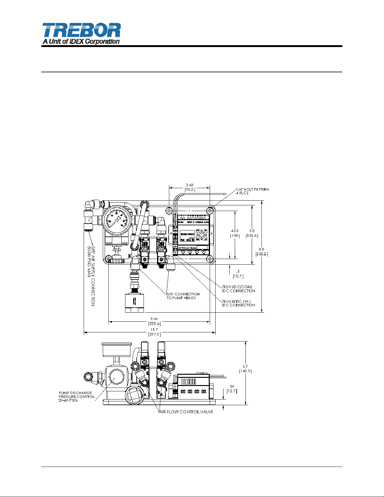
The PC15 pump controller can be installed in any orientation. Pump controller mounts
using four ¼” (6mm) bolts and should be mounted above the level of the fluid feeding the
pump. Allow clearance for tubing connectors.
Figure 6-1 Dimension (in / [mm])
PAGE 12 PURUS CP PUMP OPERATION / MAINTENANCE MANUAL
Page 13

6.3 PC15 UTILITIES / HOOK-UP
Utility Pump
Air Inlet:
Air Supply:
Power
Controller Weight:
ATTENTION: Air supplied to the PC15 pump controller must be regulated to 50 - 80 PSIG
to operate the vacuum venturi. An onboard precision regulator controls pump air supply
pressure.
Air supply connections between the pump and the pump controller are required.
NOTE: 3/8” tubing required for distances not to exceed 4 meters between the pump and
the pump controller.
24VDC is required to operate the pump controller.
o Terminal blocks are insulation displacement type. Insert 22-16 awg wires into
the indicated location and rock lever to engage connection, see Figure 6-2.
3/8” Diameter supply tube.
50-80 PSIG (.55±.03 MPa Max), clean dry air or inert
gas
24VDC - 500mA
4.4 lbs (2.0 Kg)
NOTE: Follow local wiring codes and applicable wiring standards to insure proper power
and over-current protection.
Figure 6-2: 24VDC Connection
PURUS CP PUMP OPERATION / MAINTENANCE MANUAL PAGE 13
Page 14
6.4 PC15 CONTROLLER OPERATION
Ensure that all system interlock and safety devices are functional prior to operation.
Before starting the system, it is important to read and understand the PC15PC manual.
Only trained, qualified, authorized personnel should operate this pump controller.
The controller is operated by using the buttons located on the PLR, see Table 6-1.
Table 6-1: PLC Buttons
Button Normal mode Numeric value change mode
Scroll through Menu pages. Activates setup pages when depressed
during Home page.
Enables/Disables controller
cycling.
Increases pump cycle rate on
Home page.
Decreases pump cycle rate on
Home page.
Maintenance alarm page. Displays the Maintenance alarm page
Return to home page Displays the Home page.
Activates controller when depressed during
Home page.
Increases value of digital readout.
Reduces value of digital readout.
(while digit is flashing)
6.4.a Turning Pump On and Off
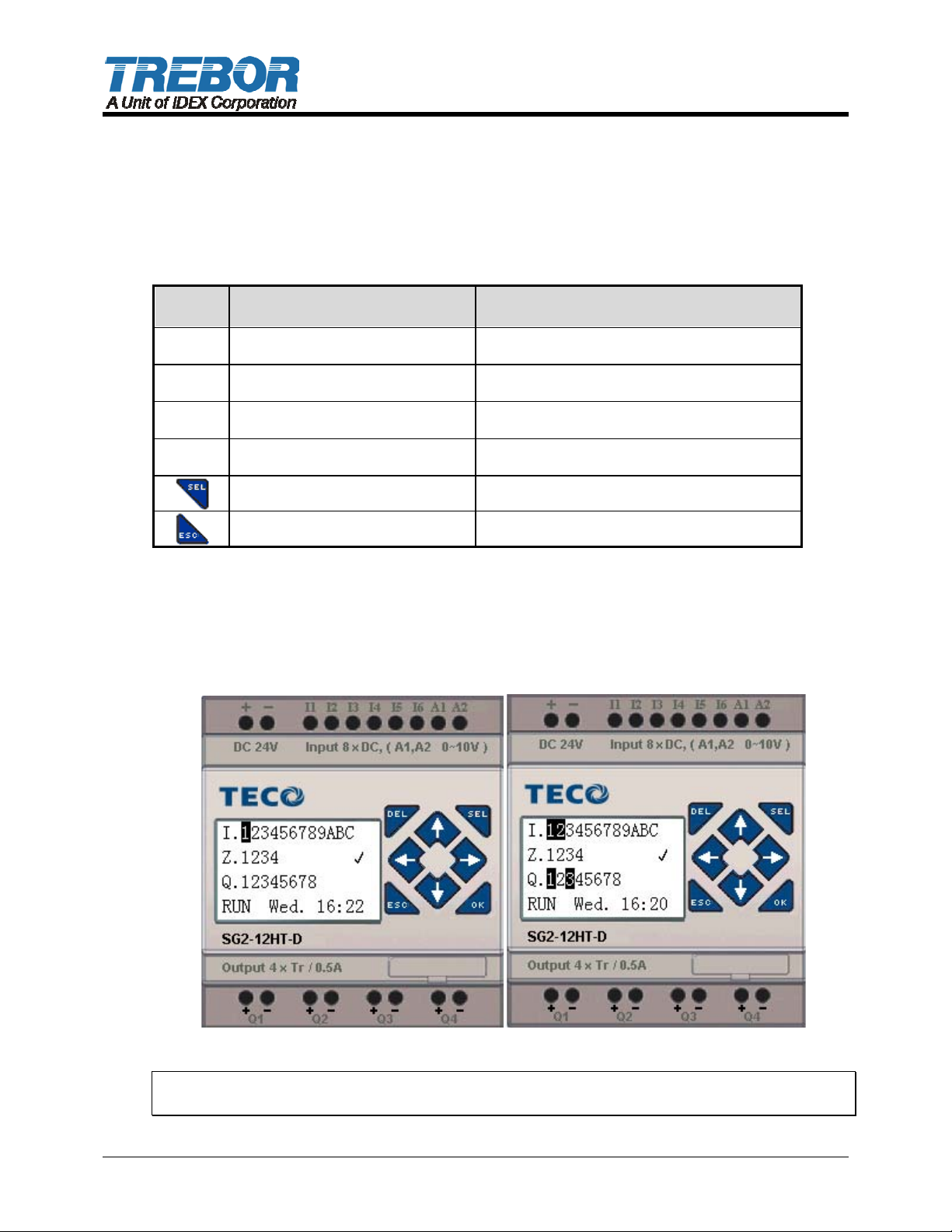
From the Home Page, pressing the RIGHT arrow key () will start and stop the
cycling of the pump controller. When activated a cursor will be located below
position 3 (Figure 6-3), accompanied by an oscillating curser between positions 1 &
2 (Figure 6-3).
Figure 6-3: Controller Off Figure 6-4: Controller Cycling
NOTE: See PC15 manual for additional instructions, requirements, limitations and
troubleshooting.
PAGE 14 PURUS CP PUMP OPERATION / MAINTENANCE MANUAL
Page 15
7 TROUBLESHOOTING
7.1 PUMP
SYMPTOM CAUSES SOLUTIONS
Bubbles in Fluid
Discharge
Fluid Leaks Weld failure Replace pump assembly
For controller troubleshooting guide refer to PC15 manual.
Diaphragm puncture Replace pump assy. (Non
Serviceable)
Loose inlet fitting Check and tighten all fittings
on the suction line feeding the
pump.
(Non Serviceable)
Loose suction or
discharge connections
Inspect tubing and tighten
fluid fittings.
PURUS CP PUMP OPERATION / MAINTENANCE MANUAL PAGE 15
Page 16

8 WARRANTY AND EXCLUSIONS
See the Trebor Standard Limited Warranty at
www.idex-hs.com/support/trebor/downloads/TreborStandardLimitedWarranty_02-07.pdf
PAGE 16 PURUS CP PUMP OPERATION / MAINTENANCE MANUAL
Page 17

9 CONTACT INFORMATION
9.1 GENERAL CONTACT INFORMATION
Web: www.teborintl.com
Phone Number: (801) 561-0303
Toll Free Number: (800) 669-1303
Fax Number: (801) 255-2312
Address: Trebor International
8100 South 1300 West
West Jordan, Utah 84088 U.S.A.
9.2 TECHNICAL SUPPORT
9.3 REGIONAL REPRESENTATIVES
Web: www.treborintl.com/about_contact_us.asp#
PURUS CP PUMP OPERATION / MAINTENANCE MANUAL PAGE 17
 Loading...