

Page 1

Phone: 800-669-1303 or 801-561-0303
Fax: 801-255-2312
e-mail: [email protected]
PC15CP PUMP
CONTROLLER
Operation / Maintenance
Manual
SERIAL NUMBER (located on top of product):
PATENTS: 06/22/12 – MPC15CP
Page 2

CONTENTS
1 PC15CP INSTALLATION ............................................................................................. 3
1.1 PC15CP OVERVIEW ......................................................................................... 3
1.2 PC15CP INSTALLATION ................................................................................... 3
1.3 PC15CP UTILITIES / HOOK-UP ........................................................................ 4
2 PC15CP CONTROLLER OPERATION........................................................................ 5
2.1 TURNING PUMP ON AND OFF ......................................................................... 5
2.2 ADJUSTING CONTROLLER .............................................................................. 5
2.2.a Suggested Controller Values ................................................................. 5
2.2.b Cycle Rate ............................................................................................. 5
2.2.c Overlap .................................................................................................. 6
2.3 MAINTENANCE ALARM .................................................................................... 6
2.3.a Maintenance Alarm Counter .................................................................. 6
2.3.b Maintenance Alarm Status .................................................................... 7
3 REMOTE OPERATION ................................................................................................ 9
4 SPARE PARTS ........................................................................................................... 10
4.1 SOLENOID VALVE REPLACEMENT .............................................................. 10
5 TROUBLESHOOTING ............................................................................................... 11
6 CONTACT INFORMATION ........................................................................................ 12
6.1 GENERAL CONTACT INFORMATION ............................................................ 12
6.2 TECHNICAL SUPPORT ................................................................................... 12
6.3 REGIONAL REPRESENTATIVES ................................................................... 12
PC15CP PUMP CONTROLLER OPERATION / MAINTENANCE MANUAL CONTENTS
Page 3

Controller Air Supply
Connection (50-80 PSIG)
Pump Air Supply
Connection
Remote Capable
Exhaust Muffler
Pump Air Supply
Regulator
Air Flow Control
Valves
1 PC15CP INSTALLATION
1.1 PC15CP OVERVIEW
The PC15CP Pump Controller is designed to operate Trebor’s Purus CP pump. Crossphase timing results in overlapping pump strokes which produces a near pulse-less pump
output.
Note: Attach the included muffler prior to installation.
1.2 PC15CP INSTALLATION
The PC15CP pump controller can be installer in any orientation. Pump controller mounts
using two ¼” (6mm) bolts and should be mounted above the level of the fluid feeding the
pump. Allow clearance for tubing connectors.
Figure 1: Dimension (mm / [in])
PC15CP PUMP CONTROLLER OPERATION / MAINTENANCE MANUAL PAGE 3
Page 4
Utility
Pump
Air Inlet:
1/4” Diameter (6mm) supply tube.
Air Supply:
80±5 PSIG (.55±.03 MPa), clean dry air or inert gas
Power
24VDC - 500mA
Controller Weight:
4.4 lbs (2.0 Kg)
1.3 PC15CP UTILITIES / HOOK-UP
ATTENTION: Air supplied to the PC15CP pump controller must be regulated to 80±5
PSIG. A secondary regulator controls pump air supply pressure.
Air supply connections between the pump and the pump controller are required.
NOTE: 3/8” tubing or larger is required for distances exceeding 3 meters between the
pump and the pump controller.
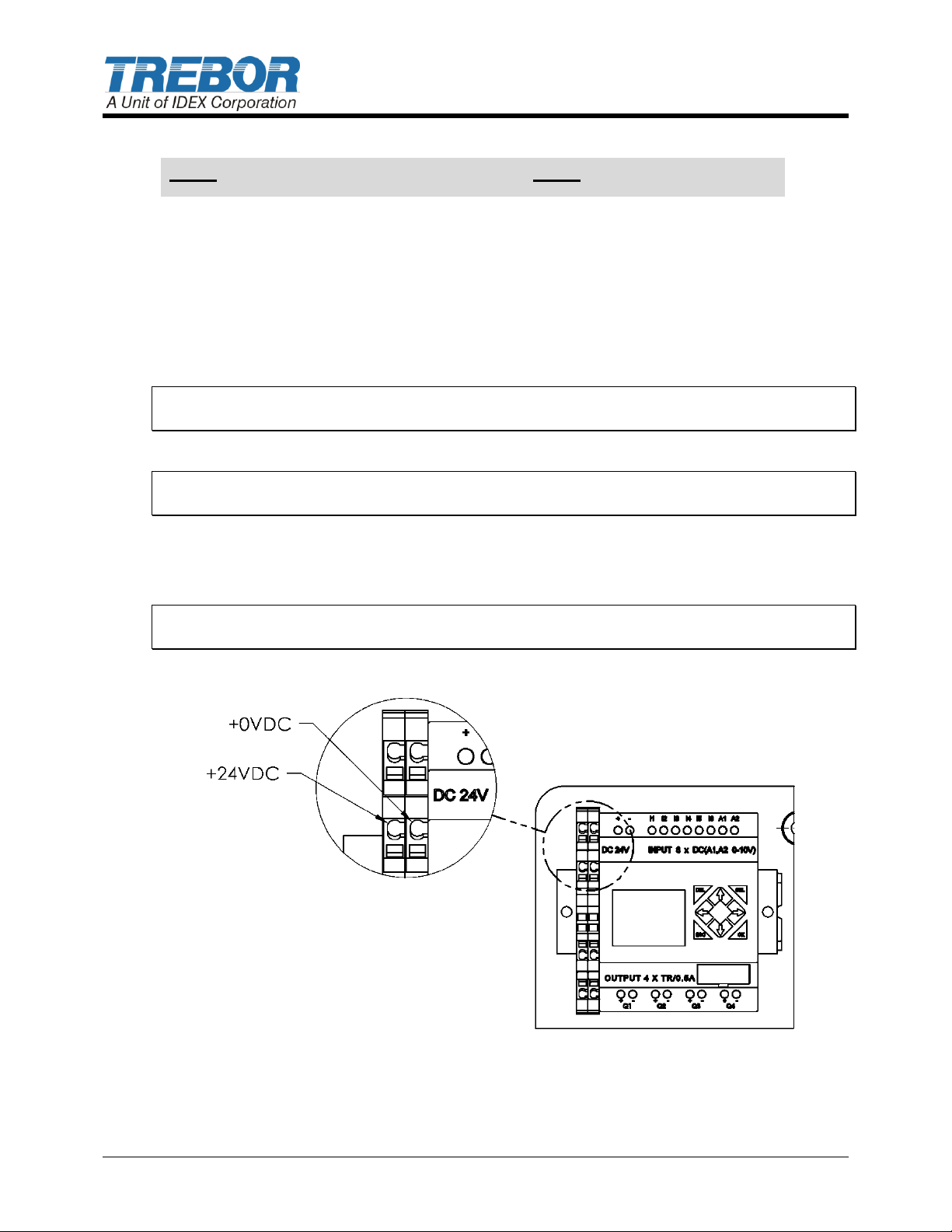
24VDC is required to operate the pump controller.
o Terminal blocks are insulation displacement type. Insert 18 gage wires into the
indicated location and push down lever to complete connection, see Figure .
NOTE: Follow local wiring codes and applicable wiring standards to insure proper power
and over-current protection.
Figure 2: 24VDC Connection
PAGE 4 PC15CP PUMP CONTROLLER OPERATION / MAINTENANCE MANUAL
Page 5
Button
Action from “Home Page”
Action from “Menu Pages”
Scroll through Menu pages
Go to Home page
Enables/Disables controller
cycling
Navigate between Menu pages
Increases pump cycle rate on
Home page
Increase values
Decreases pump cycle rate on
Home page
Decrease values
2 PC15CP CONTROLLER OPERATION
The controller is operated by using the buttons located on the PLC, see Table 2-1.
Table 2-1: PLC Buttons
2.1 TURNING PUMP ON AND OFF
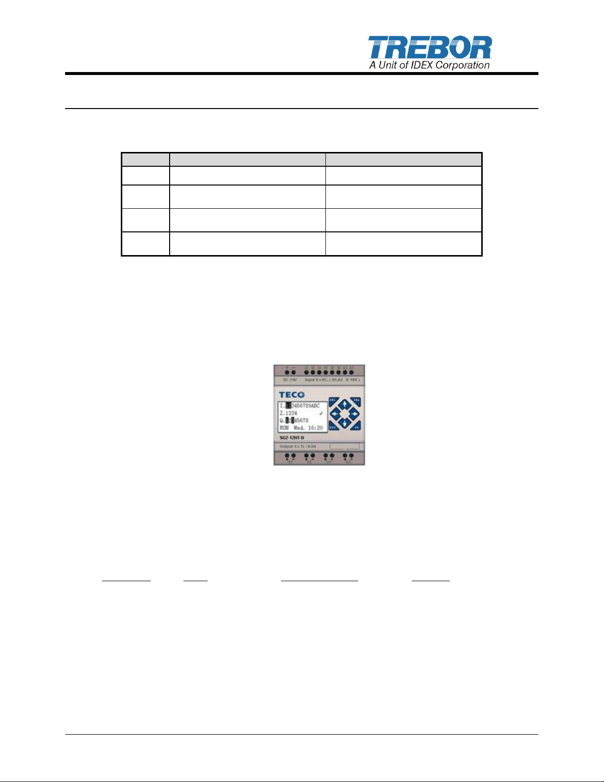
From the Home Page, pressing the RIGHT arrow key () will start and stop the
cycling of the pump controller. When cycling, a cursor will oscillate under positions
“1” & “2”.
Figure 3: Controller Cycling
2.2 ADJUSTING CONTROLLER
2.2.a Suggested Controller Values
Flow Rate CPM Air Flow Control Overlap
- 0-4 LPM: “000030” “3” Turns from closed 20
- 3-6 LPM: “000056” “2” Turns from closed 10
Please contact Trebor Service Group for any updates on these settings.
2.2.b Cycle Rate
From the Home Page, press the LEFT arrow key () to open the Cycle Rate. From there
the cycle rate can be adjusted by pressing the UP () and DOWN () arrows.
PC15CP PUMP CONTROLLER OPERATION / MAINTENANCE MANUAL PAGE 5
Page 6
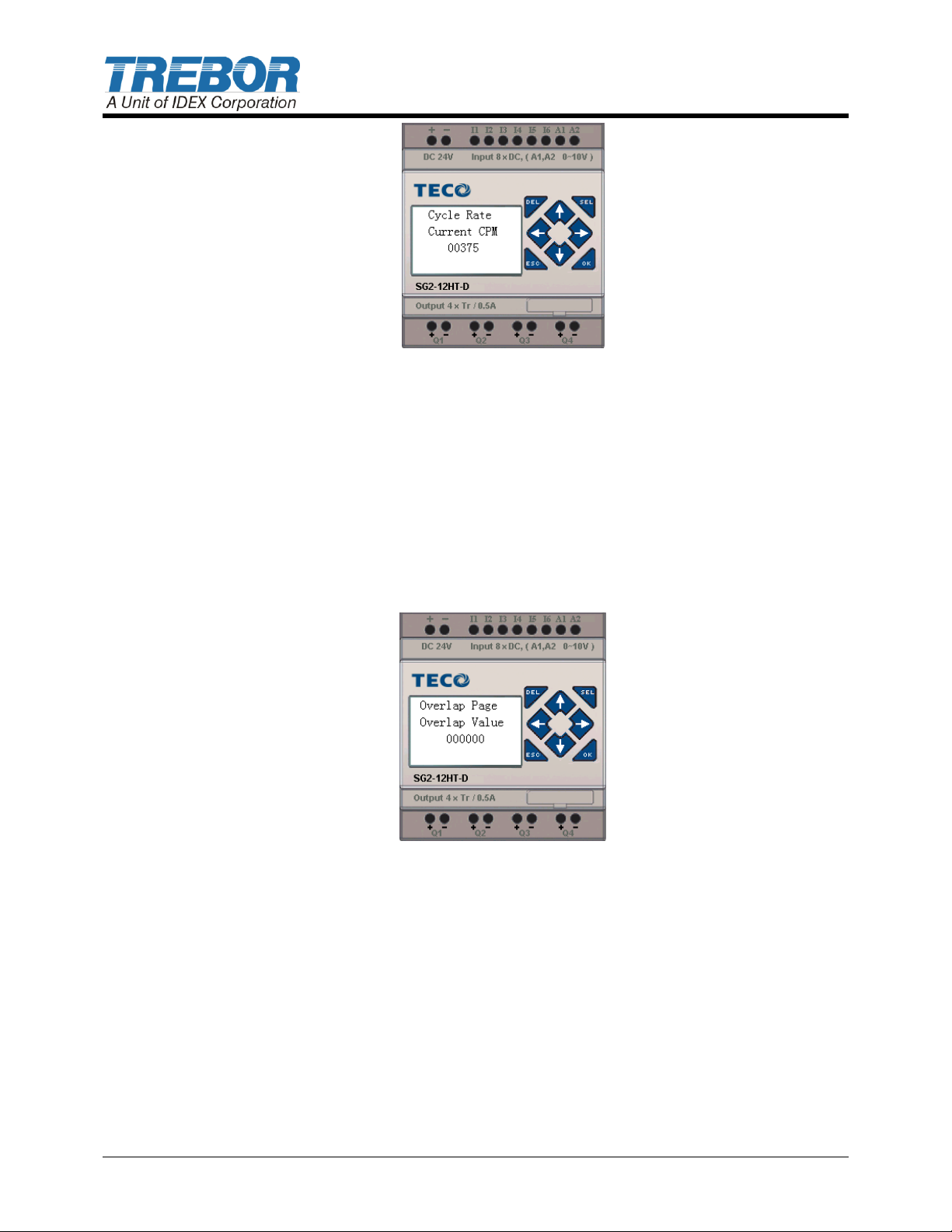
Figure 4: Cycle Rate Page
Press the LEFT arrow key () to return to the home page.
Press the RIGHT arrow key () to open the Overlap page.
2.2.c Overlap
From the Cycle Rate Page, press the RIGHT arrow key () to open the Overlap page.
From here the overlap delay can be adjust by pressing the UP () and DOWN ()
arrows.
Press the LEFT arrow key () to return to the home page.
Press the RIGHT arrow key () to open the Maintenance Alarm page.
2.3 MAINTENANCE ALARM
Figure 5: Overlap Page
2.3.a Maintenance Alarm Counter
The Maintenance Alarm Counter page is a visual display indicating how many cycles the
pump has run since the last maintenance counter reset. The top 6 digits MSB (most
significant bit) displays cycle count in millions while the lower digits LSB (least significant
bits) display values up to one million.
PAGE 6 PC15CP PUMP CONTROLLER OPERATION / MAINTENANCE MANUAL
Page 7
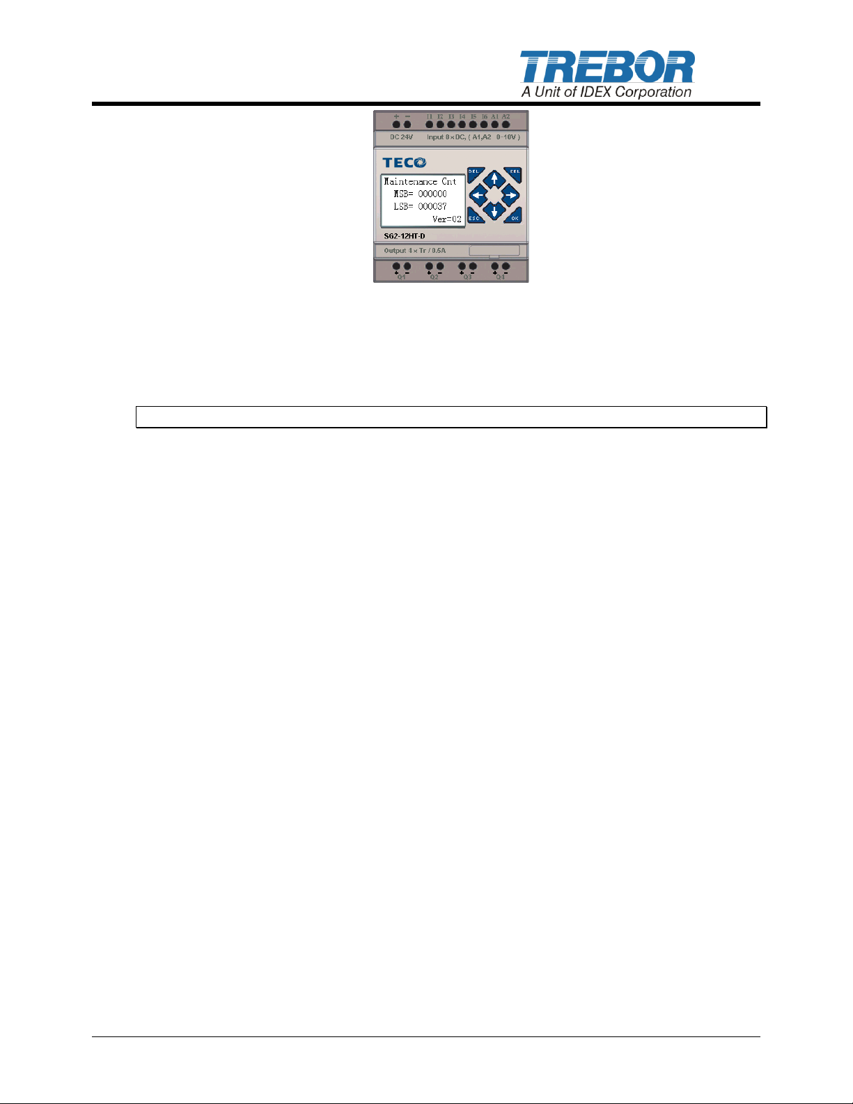
Figure 6: Maintenance Counter Display Page
When the maintenance counter MSB value exceeds the alarm setting a service alarm will
be initiated. The alarm can be acknowledged and silenced by pressing both the UP ()
and DOWN () arrow keys simultaneously while viewing this page.
Note: Resetting this counter is only possible on the Maintenance Alarm status page.
From the Maintenance Alarm Counter Page the following can be done:
Pressing the RIGHT arrow key () advances the menu screen to the maintenance
alarm page.
Pressing the LEFT arrow key () or (ESC) key will return the display to the HOME
page
Pressing both the UP () and DOWN () arrow keys simultaneously the
maintenance alarm can be silenced.
2.3.b Maintenance Alarm Status
The Maintenance Alarm status page displays the MSB value that the maintenance counter
from the previous page must reach in order to activate the maintenance alarm output Q4
(see Figure 7).
Press either the UP () or DOWN () arrow key to change the alarm set point value
(MSB). This is the value at which service is requested. When this value is zero, the
maintenance alarm is deactivated (default state).
PC15CP PUMP CONTROLLER OPERATION / MAINTENANCE MANUAL PAGE 7
Page 8
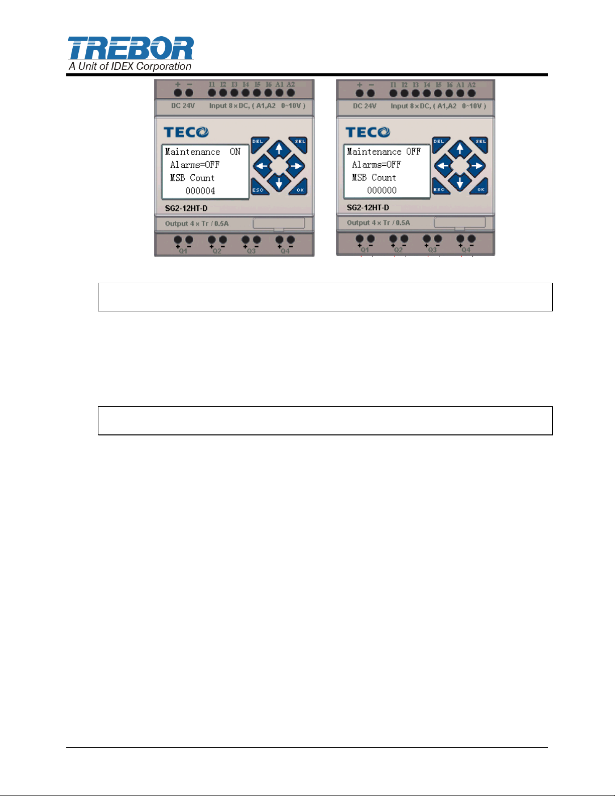
Figure 7: Maintenance Alarm ON and OFF
Note: The factory default setting of 000000 prevents the maintenance alarm from
operating. The MSB value must be ≥ 000001 to enable the Maintenance Alarm Output.
In the Figure 6, the MSB shows the factory default setting of 000000. If the setting were
set to 000010 and the maintenance counter reached 10 million cycles, the maintenance
alarm output (Q4) will be activated (ON) as indicated by the Alarms = ON/OFF line in the
display.
Pressing both the UP () and DOWN () arrow keys simultaneously while viewing this
page will reset the maintenance counter to zero resetting the alarm output.
Note: Performing this procedure resets the maintenance counter on the previous page to
zero and should only be used once maintenance has been performed as prescribed.
To silence the alarm output (Q4) return to the maintenance counter page by pressing the
RIGHT arrow key () then proceeding as outline previously.
The following actions can be done from the Maintenance Alarm page:
Pressing the RIGHT arrow key () will move to the Maintenance Alarm Counter
page
Pressing the LEFT arrow key () or (ESC) key will return the display to the HOME
page
Pressing both the UP () and DOWN () arrow keys simultaneously will reset the
maintenance counter to zero resetting the alarm output.
Pressing either the UP () or DOWN () arrow key will change the alarm set point
value (MSB). This is the value at which maintenance service is requested. When
this value is zero, the maintenance alarm is deactivated.
PAGE 8 PC15CP PUMP CONTROLLER OPERATION / MAINTENANCE MANUAL
Page 9
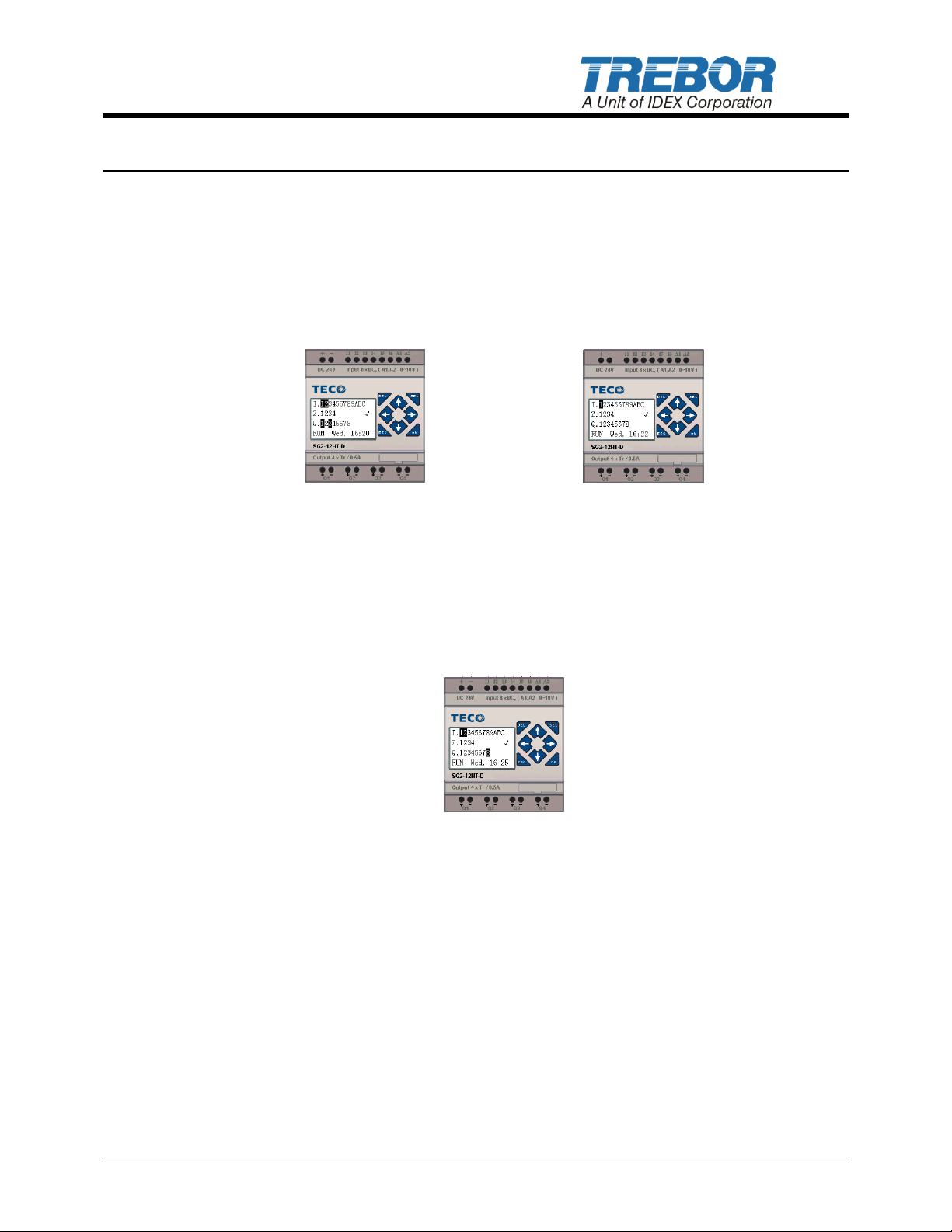
3 REMOTE OPERATION
To operate the controller by a remote signal, the following conditions must be met:
Input 1 (I1) must have a source input sufficient (>9 VDC) to activate the input as
indicated in the display below to activate the remote operation capabilities.
Input 2 (I2) must have a switched source input sufficient (>9 VDC) to activate the
input in conjunction with I1 to turn the controller ON (High Signal) or OFF (Low
Signal) as shown in the display below.
Figure 8: Remote Mode (ON) Figure 9: Remote Mode (OFF)
During remote operation, the controller can be manually stopped by pressing the RIGHT
arrow key () from the HOME page, this will locally stop controller oscillation. While in the
override stop state, the cursor under the position 8 will be ON (Figure 8).
To resume pump operation toggle input I2 changing its state (ON state to the OFF state)
resetting output 8 and then turning I2 on again. In order to turn the controller on locally exit
out of remote mode (I1 = OFF) then from the Home Page, press the RIGHT arrow key ()
will start and stop the control of the pump as normal.
Figure 10: Local Override Stop Display
Pump status feedback is provided on output Q3. As indicated in Figure 8 and 9 this output
may be wired to provide an indication signal of pump operation
PC15CP PUMP CONTROLLER OPERATION / MAINTENANCE MANUAL PAGE 9
Page 10

PART NO.
DESCRIPTION
RECOMMENDED
SPARE QTY.
98003972
Valve, Solenoid
1
4 SPARE PARTS
The following list represents spare parts we recommend for on-site system repair.
Consult factory for other parts not shown above.
4.1 SOLENOID VALVE REPLACEMENT
Remove nut from machine screw mounting valve to mounting panel.
Identify and remove air transfer tubes from push connect ports.
Disconnect solenoid electrical connectors.
Remove and replace valve assembly.
Reverse removal procedure for reassembly.
PAGE 10 PC15CP PUMP CONTROLLER OPERATION / MAINTENANCE MANUAL
Page 11
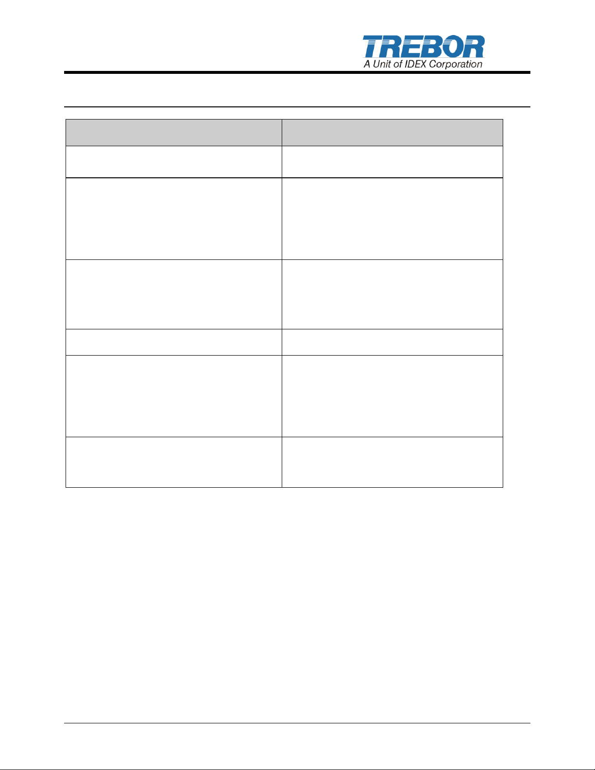
SYMPTOMS
SOLUTIONS
Pump turns on when on/off switch is
activated, but the pump is running slow
Increase cycle rate setting: maximum of
375.
Pump flow does not increase with cycle
rate
Confirm regulated air supply pressure at
50-80 psig.
Increase pump discharge pressures if
discharge pressure is not surging!
Reduce inlet suction (Lift) requirements.
Pump is surging (discharge pressure
variation >4 psig)
Initiate controller calibration to reduce
pulsation. Contact Trebor
Reduce inlet suction requirements.
Increase cycle rate.
Controller display does not turn on
Check power supply voltage >19VDC.
Pump will not run
Check pump regulator pressure is above
15 psig.
Check controller air supply pressure <>
50-80 psig.
Check if remote operation enabled.
Pump will not prime
Increase cycle rate.
Check controller supply pressure is >50
PSIG.
5 TROUBLESHOOTING
PC15CP PUMP CONTROLLER OPERATION / MAINTENANCE MANUAL PAGE 11
Page 12

6 CONTACT INFORMATION
6.1 GENERAL CONTACT INFORMATION
Web: www.treborintl.com
Phone Number: (801) 561-0303
Toll Free Number: (800) 669-1303
Fax Number: (801) 255-2312
Address: Trebor International
8100 South 1300 West
West Jordan, Utah 84088 U.S.A.
6.2 TECHNICAL SUPPORT
6.3 REGIONAL REPRESENTATIVES
Web: www.treborintl.com
PAGE 12 PC15CP PUMP CONTROLLER OPERATION / MAINTENANCE MANUAL
 Loading...