

Page 1

Phone: 800-669-1303 or 801-561-0303
Fax: 801-255-2312
e-mail: [email protected]
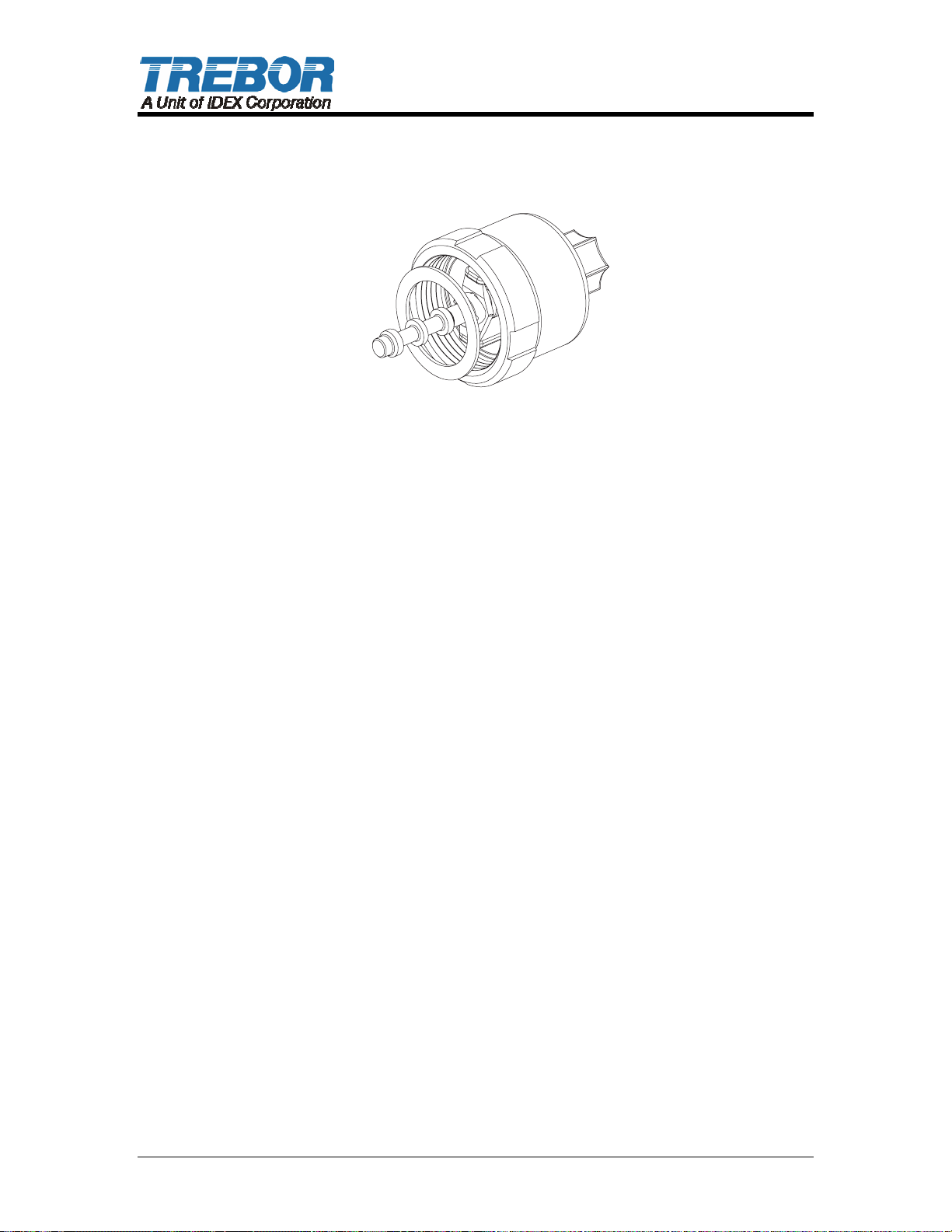
PC7 PUMP
CONTROLLER
Operation / Maintenance
Manual
SERIAL NUMBER (located on top of product):
PATENTS: U.S. 09642426, U.S. 06106246, U.S. 05971402, U.S. 05370507 02/16/05 – MPC7-PRJ0305
Page 2

CONTENTS
1 INSTALLATION............................................................................................................3
1.1 UNPACKING ......................................................................................................3
1.2 UTILITIES / HOOK-UP.......................................................................................3
2 OPTIONS......................................................................................................................5
2.1 UNIT IS AVAILABLE IN BOTH PFA AND PP CONSTRUCTION......................5
3 START-UP....................................................................................................................6
3.1 PERFORMANCE CHARTS................................................................................7
4 MAINTENANCE ...........................................................................................................8
4.1 PREVENTIVE MAINTENANCE SCHEDULE.....................................................8
4.1.a Preventive Maintenance Record...........................................................9
4.2 RECOMMENDED SPARE PARTS ..................................................................10
4.3 TOOLS..............................................................................................................10
4.4 PARTS ILLUSTRATION – PC7........................................................................10
4.5 PARTS LIST – PC7F........................................................................................11
4.6 PARTS LIST – PC7P........................................................................................11
4.7 CLEAN-UP........................................................................................................12
4.8 DISASSEMBLY ................................................................................................12
4.9 ASSEMBLY ......................................................................................................12
5 TROUBLESHOOTING ...............................................................................................15
6 WARRANTY .......................................................................................................16
PC7 CONTROLLER OPERATION / MAINTENANCE MANUAL CONTENTS
Page 3
1 INSTALLATION
1.1 UNPACKING
After unpacking, the pump should be checked for any damage that may have
occurred during shipment. Damage should be reported to the carrier
immediately.
The following items should be included within the shipping container:
Qty Item Description
1 PC7F or PC7P PC7 PUMP CONTROLLER
1 PC7-Manual Manual, PC7 Pump Controller
1.2 UTILITIES / HOOK-UP
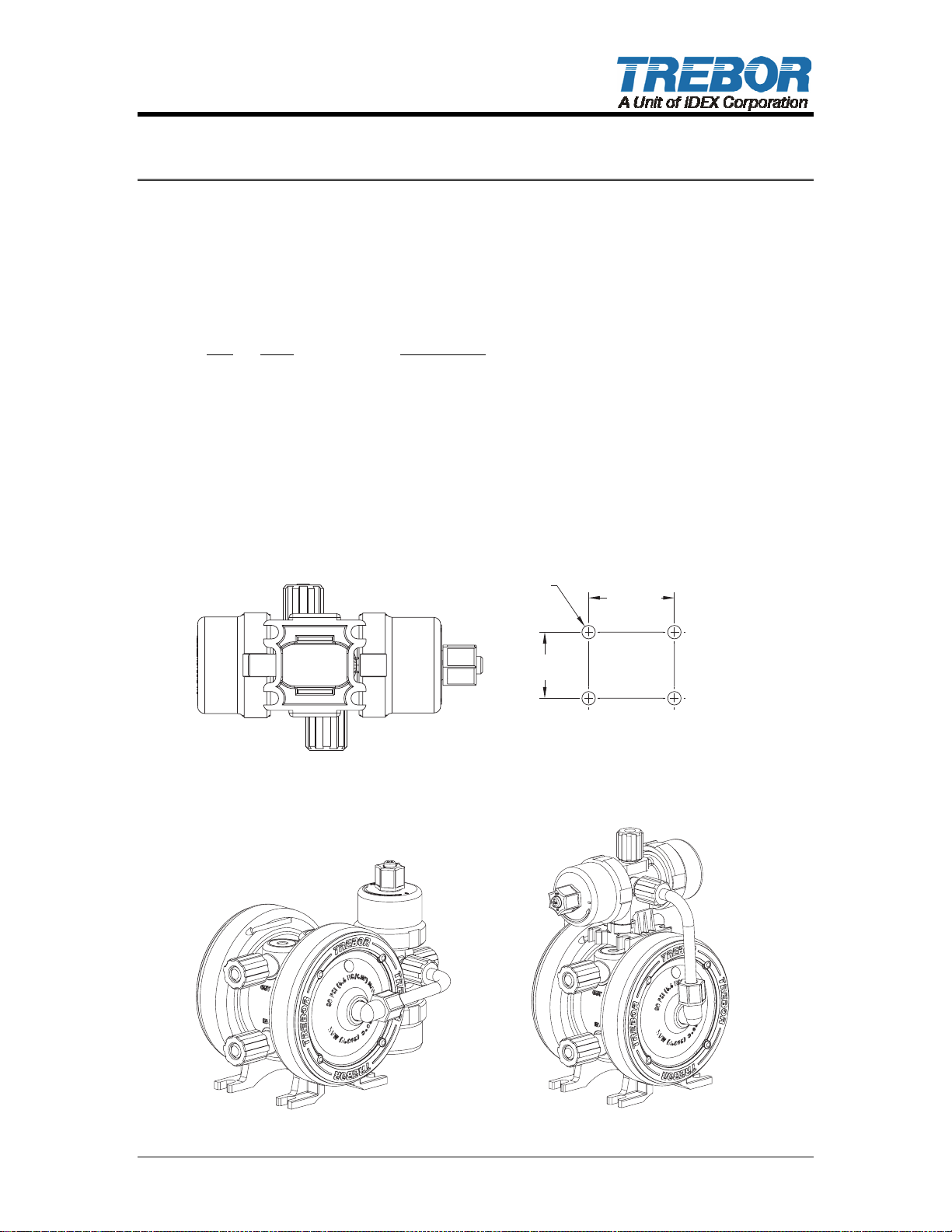
The controller can be mounted by any of three methods. It can be bolted to a wall
or deck using the snap on base slots as shown below using four ¼”(6mm) bolts
in the pattern shown below.
CONTROLLER - BOTTOM VIEW
5/16"
DIA
4X
1 7/16"1 7/16"
BOLT PATTERNBOLT
MTD0616
1 7/8"1 7/8"
PATTERN
MTD0617
MTD0618
PUMP INSTALLATION - BACK PUMP INSTALLATION - TOP
PC7 CONTROLLER OPERATION / MAINTENANCE MANUAL PAGE 3
Page 4
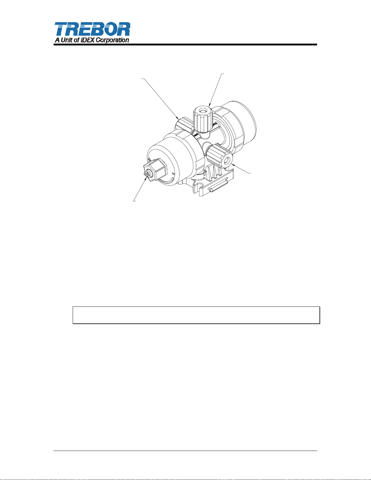
HEAD 1HEAD 1
CONNECTION
SPEED
ADJUSTMENT
SCREW
AIR INLETAIR INLET
CONNECTION
HEAD 2HEAD 2
CONNECTION
MTD0619
Air Inlet: 3/8” Flaretek (3/8” OD TUBING)
Air Supply: 20-80 PSIG (1.4 – 5.4 BAR), CLEAN DRY AIR OR NITROGEN.
Head Ports: 3/8” Flaretek (3/8” OD PFA TUBING)
Recommended Maximum Operating Levels: 80 psig (5.4 bar)
ATTENTION: The controller should be operated with clean, dry air or nitrogen.
Particulate, water and oils in the air supply can damage the controller.
PAGE 4 PC7 CONTROLLER OPERATION / MAINTENANCE MANUAL
Page 5

2 OPTIONS
2.1 UNIT IS AVAILABLE IN BOTH PFA AND PP CONSTRUCTION
The PFA unit exterior parts are molded using PFA (Fluoroplastic) and the shuttle
assembly is constructed of PEEK & PPS. The PFA unit is intended for severe
applications and for compliance with FM4910.
The PP unit exterior parts are molded using Polypropylene (Polyolefin) and the
shuttle assembly is constructed of PEEK & PPS. This unit is intended as a lower
cost option with similar service life where exposure to oxidizing acids is limited.
PC7 CONTROLLER OPERATION / MAINTENANCE MANUAL PAGE 5
Page 6
3 START-UP
• Controller air supply pressure must be regulated to a maximum of 80 psig.
• Open the fluid suction (IN) line valve, if necessary.
• Open the fluid discharge (OUT) line valve, if necessary.
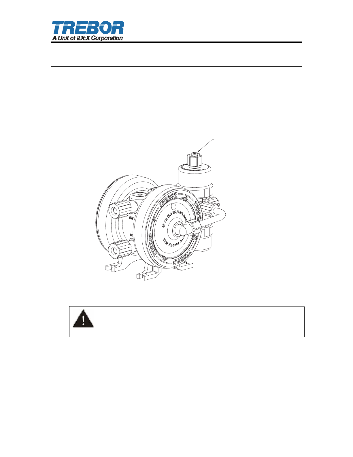
• Adjust the speed control screw fully Clockwise (CW) until fully retracted.
Warning! Do not apply too much torque to screw or damage may result.
SPEED CONTROL SCREWSPEED CONTROL SCREW
MTD0629
• Open air supply line to operate pump. Operate pump at 20 psig initially to
prime pump.
CAUTION: When handling potentially dangerous fluids under pressure,
the pump and its fittings should be placed in an enclosure away from operators.
PAGE 6 PC7 CONTROLLER OPERATION / MAINTENANCE MANUAL
Page 7

3.1 PERFORMANCE CHARTS
Pumping capacity is a function of air supply pressure and volume, suction head,
suction line restrictions, discharge head, discharge line restriction, and fluid
specific gravity and viscosity.
Air Supply
Pressure
(PSIG)
20 0 80
20 1/2 30
40 0 135
40 2 70
60 0 190
60 2 80
80 0 240
80 2 110
Turns on
adjustment
screw
Cycles
Per
Minute
(+/-15%)
NOTE: Test information is based on specific conditions and limited sampling.
Use for general reference only. This information is preliminary and may be
changed at a future date.
PC7 CONTROLLER OPERATION / MAINTENANCE MANUAL PAGE 7
Page 8
4 MAINTENANCE
4.1 PREVENTIVE MAINTENANCE SCHEDULE
The following maintenance schedule is recommended to optimize pump
performance and minimize failures.
Adhering to the recommended preventative maintenance schedule along with
periodic inspection of the pump will ensure continued efficient operation and
overall reliable pump performance.
It is recommended that the Preventive Maintenance Record (Section 4.1.a) be
copied, maintained and kept with this unit for future reference.
PC7 Maintenance
Replacement Inspection
Component /
1 Year
X Fitting Nuts (Connections) P/N (9002914)
X X Detent Legs P/N (305-PD)
X X Shuttle Spool P/N (305-PJ)
X X Spring Bar P/N (305-QA)
X Muffler Media (PC7 Controller) P/N (305-FR)
2 Year
1 Year
6 months
2 Year
Comments
PAGE 8 PC7 CONTROLLER OPERATION / MAINTENANCE MANUAL
Page 9

4.1.a Preventive Maintenance Record
Company Name: _____________________________________________________
Company Address:
_____________________________________________________
Product: _________________ Serial Number: ________________
Date: ________ Tech: _____ Notes: ________________________________________
________________________________________
Date: ________ Tech: _____ Notes: ________________________________________
________________________________________
Date: ________ Tech: _____ Notes: ________________________________________
________________________________________
Date: ________ Tech: _____ Notes: ________________________________________
________________________________________
Date: ________ Tech: _____ Notes: ________________________________________
________________________________________
Date: ________ Tech: _____ Notes: ________________________________________
________________________________________
Date: ________ Tech: _____ Notes: ________________________________________
________________________________________
Date: ________ Tech: _____ Notes: ________________________________________
________________________________________
Date: ________ Tech: _____ Notes: ________________________________________
________________________________________
Date: ________ Tech: _____ Notes: ________________________________________
________________________________________
Date: ________ Tech: _____ Notes: ________________________________________
________________________________________
Date: ________ Tech: _____ Notes: ________________________________________
________________________________________
Date: ________ Tech: _____ Notes: ________________________________________
________________________________________
Date: ________ Tech: _____ Notes: ________________________________________
________________________________________
Date: ________ Tech: _____ Notes: ________________________________________
________________________________________
Date: ________ Tech: _____ Notes: ________________________________________
________________________________________
Date: ________ Tech: _____ Notes: ________________________________________
________________________________________
Date: ________ Tech: _____ Notes: ________________________________________
________________________________________
Date: ________ Tech: _____ Notes: ________________________________________
________________________________________
Date: ________ Tech: _____ Notes: ________________________________________
________________________________________
Date: ________ Tech: _____ Notes: ________________________________________
________________________________________
Date: ________ Tech:
Date: ________ Tech: _____ Notes: ________________________________________
Date: ________ Tech: _____ Notes: ________________________________________
_____ Notes: ________________________________________
________________________________________
________________________________________
________________________________________
PC7 CONTROLLER OPERATION / MAINTENANCE MANUAL PAGE 9
Page 10
4.2 RECOMMENDED SPARE PARTS
There are no recommended spare parts for the Purus 20 pump due to it’s welded
and sealed construction. However there are spare parts available for rebuild of
the PC7 pump controller.
PC7 Pump Controller
305-PD 4 EA LEG, DETENT
305-QA 2 EA SPRING BAR, DETENT
305-P016 2 EA SEAL, PTFE, 1.75 X 1.33 X .02 (PC7F ONLY!)
305-P015 2 EA SEAL, PTFE, 1.82 X 1.33 X .02 (PC7P ONLY!)
305-PJ 1 EA SPOOL, SHUTTLE
305-P040 1 EA SCREW, SPEED ADJUSTMENT
305-P048 1 EA FERRULE, PTFE
305-FR 5 EA PAD, MUFFLER
4.3 TOOLS
The only tool requirements are a Phillips #2 and Straight screwdriver.
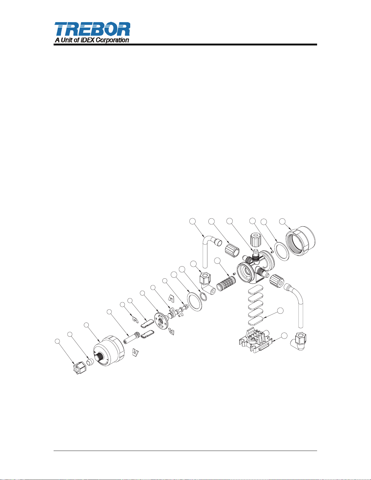
4.4 PARTS ILLUSTRATION – PC7
14
15
16
17
10
18
12
11
10
9
8
7
6
5
4
3
2
1
13
19
20
MTD0615
PAGE 10 PC7 CONTROLLER OPERATION / MAINTENANCE MANUAL
Page 11
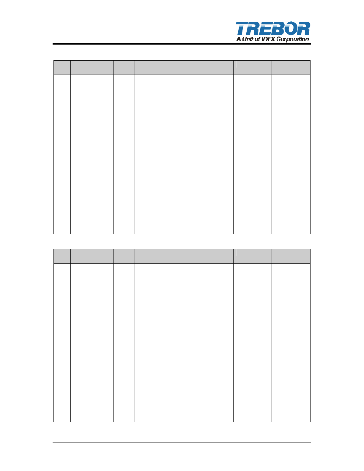
4.5 PARTS LIST – PC7F
ILL
PART NO QTY DESCRIPTION PM YEAR # MATERIAL
NO
1 305-P049 1 NUT, COMPRESSION,PVDF, 3/8 PVDF
2 305-P048 1 FERRULE, PTFE, PC7 PTFE
3 305-P047 1 CAP,PFA,ADJUST,PC7 PFA
4 305-040 1 SCR, ADJUST,PC7 PVDF
5 305-PD 4 LEG,DETENT,PC7 DELRIN
6 305-QA 2 SPRING BAR,DETENT,OSCILLATOR PEEK
7 305-QB 1 PLATE,SUPPORT,PC7 PVDF
8 305-P007 2 SCR,NYLON,#8-32x.31,SLOVHD NYLON
9 305-PJ 1 SPOOL,SHUTTLE,OSCILLATOR PEEK
10 305-P016 2 SEAL,PTFE,GORTEX,1.75x1.33x.02 PTFE
11 305-P050 1
12 305-P014 2 FTG,PVDF,3/8" ME PVDF
13 AK058 1 ASSY,SHUTTLE SLEEVE CERAMIC
14 305-P013 2 TUBE,TRANSFER,PFA PFA
15 98002913 3 NUT,PVDF,FLR,3/8T PVDF
16 305-PA 1 BODY,OSCILLATOR,PFA,PC7 PFA
17 AW036-01 2 ORIFICE, PRESS-IN .024 PEEK
18 305-P011 1 CAP,PFA,PC7 PFA
19 305-FR 4 PAD,MUFFLER,PP,25 MICRON PP
20 305-QF 1 BASE,PFA,PC7 PFA
RING,SPLIT,SINGLE TURN,PTFE,016
PTFE
4.6 PARTS LIST – PC7P
ILL
NO
1 305-P052 1 NUT, COMPRESSION, PP, 3/8 PP
2 305-P048 1 FERRULE, PTFE, PC7 PTFE
3 305-P046 1 CAP,PP, ADJUST,PC7 PP
4 305-P040 1 SCR, ADJUST,PC7 PVDF
5 305-PD 4 LEG,DETENT,PC7 DELRIN
6 305-QA 2 SPRING BAR,DETENT,OSCILLATOR PEEK
7 305-QB 1 PLATE,SUPPORT,PC7 PVDF
8 305-P007 2 SCR,NYLON,#8-32x.31,SLOVHD NYLON
9 305-PJ 1 SPOOL,SHUTTLE,OSCILLATOR PEEK
10 305-P016 2 SEAL,PTFE,GORTEX,1.75x1.33x.02 PTFE
11 305-P050 1
12 305-P045 2 FTG,PP,3/8" ME PP
13 AK058 1 ASSY,SHUTTLE SLEEVE CERAMIC
14 305-P013 2 TUBE,TRANSFER,PFA PFA
15 98002913 3 NUT,PVDF,FLR,3/8T PVDF
16 305-P006 1 BODY,OSCILLATOR,PP PC7 PP
17 AW036-01 2 ORIFICE, PRESS-IN .024 PEEK
18 305-P002 1 CAP,PFA,PC7 PFA
19 305-FR 4 PAD,MUFFLER,PP,25 MICRON PP
20 305-P005 1 BASE,PP,PC7 PP
PART NO QTY DESCRIPTION PM YEAR # MATERIAL
RING,SPLIT,SINGLE TURN,PTFE,016
PTFE
PC7 CONTROLLER OPERATION / MAINTENANCE MANUAL PAGE 11
Page 12
4.7 CLEAN-UP
Due to possible contamination all components must be flushed clean and
neutralized before disassembly to prevent fluid contact with personnel.
4.8 DISASSEMBLY
To disassemble PC7 pump controller for service, remove controller from pump by
disconnecting the flare fittings on the PC7 from the transfer tubes connecting it to
the pump.
Caution: For safety make sure air supply to PC7 has been shut off prior to
removal of supply line.
• Unscrew Adjustment Cap from controller body and carefully twist shuttle
spool from sleeve by rotating cap assembly.
• Gently remove the cap seal from the seat inside the cap to prevent any
damage or possible scratches to sealing surface. Replacement of seal is
recommended after service.
• Use a straight blade screwdriver to remove the two retaining screws from the
support plate. Next loosen compression nut and ferrule from adjustment
screw and gently push the adjustment screw out of the cap by pressing on
the end. This assembly contains the only serviceable items. See exploded
assembly for part numbers and part locations.
• Inspect parts for wear and replace if necessary.
4.9 ASSEMBLY
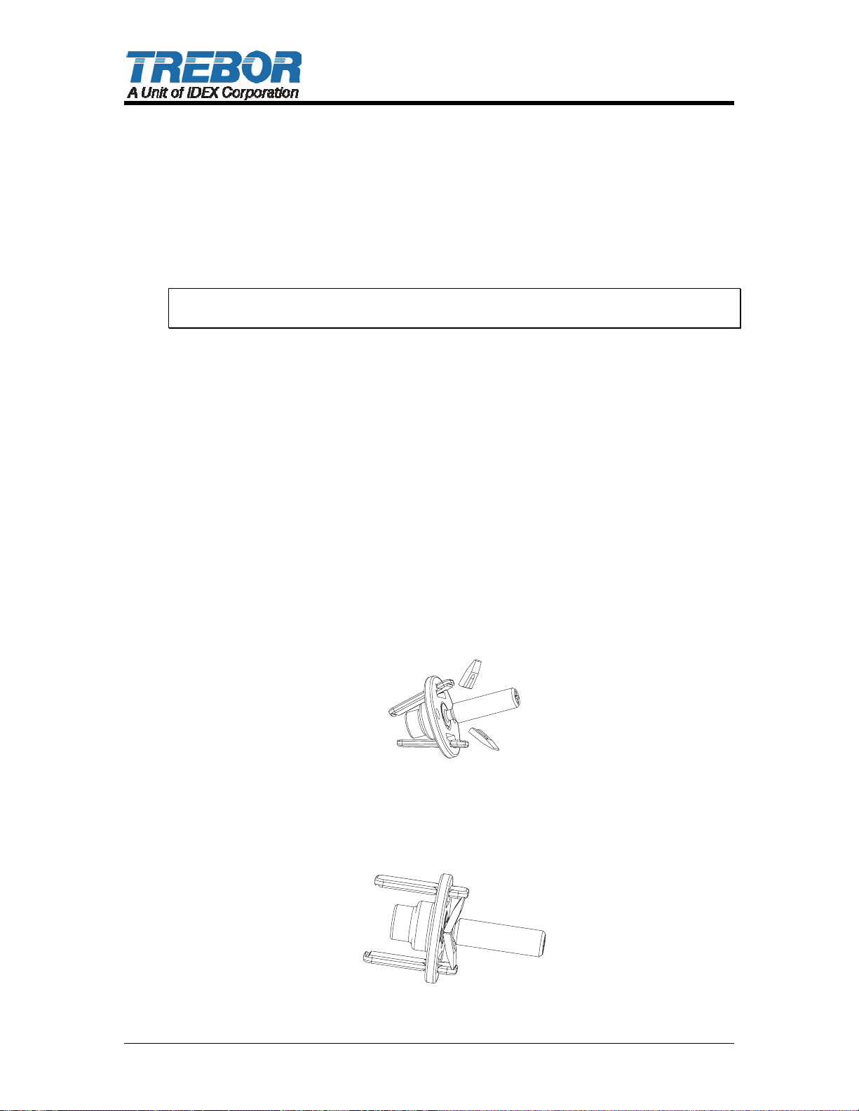
• To reassemble detent, twist the adjustment screw into the support plate and
then insert 2 each spring bars into slots as per figure 1.
• Next insert 2 each detent legs as shown in Figure 1 and open spring bars to
lock assembly as shown in Figure 2.
MTD0 3 6 0
Figure 1
MTD06 1 3
Figure 2
PAGE 12 PC7 CONTROLLER OPERATION / MAINTENANCE MANUAL
Page 13
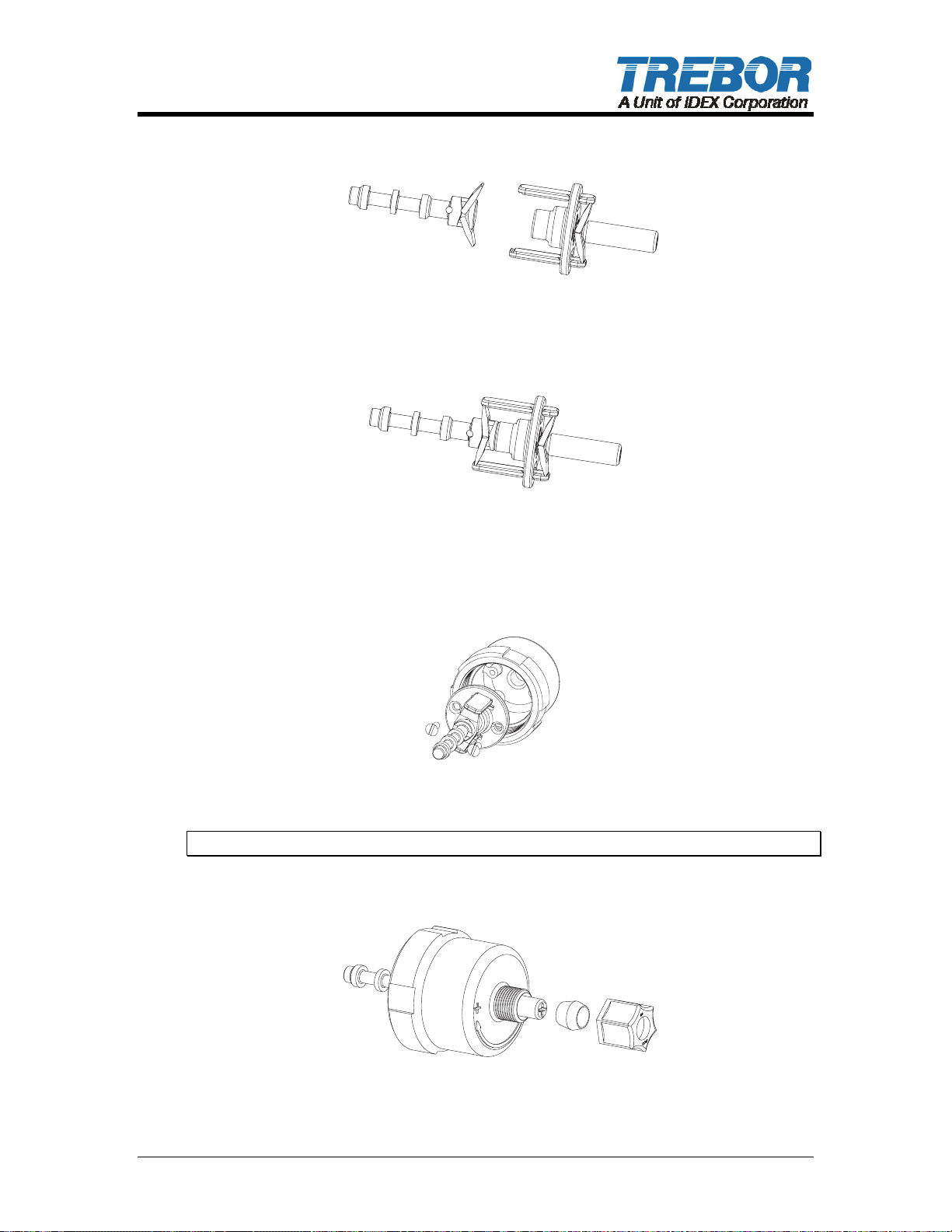
• Lastly insert 2 ea. detent legs into slots on shuttle spool as shown in Figure 3
and insert into previous assembly.
MTD0632
Figure 3
• See completed detent assembly illustrated in Figure 4.
M D 63
T 0 3
Figure 4
• Insert detent assembly into adjustable cap as shown here and install 2 each
retaining screws.
MTD0634
Figure 5
Note: Do not over tighten screws. Cap threads are easily stripped.
• Install ferrule onto adjustment screw with the longest taper toward the
adjustment cap. Then install compression nut onto cap per figure 6.
MTD0 3 6 5
Figure 6
PC7 CONTROLLER OPERATION / MAINTENANCE MANUAL PAGE 13
Page 14
• Tighten nut finger tight to engage compression seal.
• Insert Gortex seal into thread end of adjustable cap assembly onto sealing
land as shown.
M D 6 6M D 6 6
T 0 3T 0 3
Figure 7
• Screw cap assembly with seal onto the open end of body assembly carefully
inserting shuttle spool into valve body and engage air seal completely.
• Cap requires only moderate installation torque to activate seal. Over
tightening can dislocate seal gasket preventing oscillation of the controller
valve.
PAGE 14 PC7 CONTROLLER OPERATION / MAINTENANCE MANUAL
Page 15

5 TROUBLESHOOTING
Controller Will Not Operate or Cycles Erratically
Cause: Solution:
PC7 cap seal failure
•
Debris in shuttle valve
•
Insuffisant air pressure
•
Adjustment Screw Seal failure
•
Spring bar failure
•
Remove caps from PC7 and replace PTFE cap seal.
•
Isopropyl alcohol clean the shuttle sleeve and spool assy.
•
Increase regulated supply pressure or check control
•
valves for proper operation.
Rotate PC7 speed control screw CW until it stops. Then
readjust for correct speed.
Replace adjustment screw assy.
•
Spring bar needs replacement if not flat.
•
PC7 CONTROLLER OPERATION / MAINTENANCE MANUAL PAGE 15
Page 16
6 WARRANTY
PC7F OR PC7P CONTROLLER
TREBOR International, Inc. warrants to the purchaser of new equipment
manufactured by TREBOR to be free from defects in material and workmanship
when used for its intended purpose under normal operating conditions, and
maintained according to the Operation/Maintenance Manual.
TREBOR’s obligation under this warranty is limited to repairing or replacing, at
TREBOR’s option and at the TREBOR factory, any part or parts thereof which
shall, within 1 year after delivery thereof to the original purchaser, be
demonstrated to TREBOR’s satisfaction to have been defective. This warranty
may be transferred to subsequent owners. The warranty period is based on the
original ship date from the factory. All warranty related freight costs shall be
borne by the customer.
Excessive wear to pump components caused by pumping abrasive solutions or
chemicals, as well as damage caused by ingesting foreign objects shall not be
covered by this warranty.
This warranty shall not apply to any equipment which, in the judgment of
TREBOR, shall have been repaired or altered outside TREBOR’s factory in any
way, so as to affect its performance or reliability; subjected to misuse, negligence
or accident; or used other than in accordance with TREBOR’s printed
instructions.
There are no terms, conditions or warranties, expressed, implied or
statutory, of merchantability, fitness, capacity, or otherwise, of the goods
ordered, other than, or different from, the warranty set forth above. This
warranty takes precedence over any other warranty, expressed or implied.
TREBOR neither assumes, nor authorizes any other party to assume for it, any
liability in connection with said equipment except as set forth above.
PAGE 16 PC7 CONTROLLER OPERATION / MAINTENANCE MANUAL
 Loading...