

Page 1

Phone: 800-669-1303 or 801-561-0303
Fax: 801-255-2312
e-mail: [email protected]
Q-SERIES DI WATER
HEATER
Operation / Maintenance
Manual
SERIAL NUMBER:
PATENTS: U.S. 5971402, U.S. 6433319, U.S. 6479094B2, U.S. 6544583B2, 4/21/10 – MQ-B
U.S. 6580061B2, U.S. 6663914, U.S 6674053B2;
ADDITIONAL PATENTS PENDING
Page 2
CONTENTS
1 INTRODUCTION ........................................................................................................................................3
2 SAFETY ......................................................................................................................................................5
2.1 SAFETY MESSAGE CONVENTIONS ............................................................................................5
2.1.a Danger ...........................................................................................................................5
2.1.b Warning ..........................................................................................................................5
2.1.c Caution ...........................................................................................................................6
2.2 EMERGENCY OFF (EMO) .............................................................................................................6
2.3 LOCKOUT / TAGOUT ....................................................................................................................7
2.3.a Preliminary .....................................................................................................................7
2.3.b Definitions ......................................................................................................................7
2.3.c Machine Lockout with access panels installed ................................................................7
2.3.d Machine Start-Up with access panels installed ...............................................................8
2.3.e Machine Lockout with access panels removed ...............................................................8
2.3.f Machine Start-Up with access panels removed ..............................................................8
2.4 SEISMIC PROTECTION ................................................................................................................9
3 INSTALLATION ........................................................................................................................................ 10
3.1 UNPACKING ................................................................................................................................ 10
3.2 LOCATION ................................................................................................................................... 10
3.3 UTILITY HOOK-UP ...................................................................................................................... 10
4 START-UP ................................................................................................................................................ 13
4.1 PRE-START INSPECTION .......................................................................................................... 13
4.1.a Verify Shipping Condition ............................................................................................. 13
4.1.b Hazardous Power Terminals ......................................................................................... 13
4.1.c Electrical Inspection ..................................................................................................... 13
4.1.d Plumbing Leak Check ................................................................................................... 13
4.2 SYSTEM POWER ........................................................................................................................ 14
4.3 HEATING WATER ....................................................................................................................... 14
5 HEATER OPERATION ............................................................................................................................. 15
5.1 BACKGROUND COLOR CONVENTIONS FOR BUILT-IN GRAPHICAL USER INTERFACE ...... 15
5.2 LOCAL OPERATION THROUGH BUILT-IN GRAPHICAL USER INTERFACE ............................ 15
5.2.a Home Page ........................................................................................................ 16
5.2.b Alarm page ......................................................................................................... 16
5.2.c Configuration Page ............................................................................................. 18
5.2.d Plot Page ........................................................................................................... 19
5.3 REMOTE OPERATION OVER AN EXTERNAL HARDWARE INTERFACE ................................. 20
6 PROCESS INTERLOCKS ......................................................................................................................... 22
7 SYSTEM SHUT DOWN ............................................................................................................................ 24
8 MAINTENANCE ........................................................................................................................................ 25
9 TROUBLESHOOTING .............................................................................................................................. 30
10 WARRANTY ............................................................................................................................................. 31
5.3.a Remote Communication via Modbus/RTU .................................................................... 20
6.1 LOW FLUID PRESSURE SENSOR ............................................................................................. 22
6.2 LIQUID LEVEL SENSOR ............................................................................................................. 22
6.3 ELEMENT OVER TEMPERATURE SENSOR .............................................................................. 23
6.4 LIQUID LEAK SENSOR ............................................................................................................... 23
6.5 OVERPRESSURE RELIEF FITTING ........................................................................................... 23
8.1 REPAIR INSTRUCTIONS ............................................................................................................ 25
8.1.a Heater Element Check ................................................................................................. 25
8.1.b Heater Replacement ................................................................................................ ..... 25
8.1.c Liquid Level Sensor Calibration .................................................................................... 27
8.1.d Draining the System ..................................................................................................... 27
8.1.e Leaks............................................................................................................................ 27
8.1.f Overpressure Relief Fitting Replacement ..................................................................... 28
8.2 PREVENTIVE MAINTENANCE SCHEDULE................................................................................ 28
See Appendix for specific system requirements.
Q-SERIES DI HEATER OPERATION / MAINTENANCE MANUAL CONTENTS
Page 3
1 INTRODUCTION
Q-SERIES DI WATER HEATER
TREBOR’s Q-Series DI water heater will meet your most stringent
application requirements for process cleanliness and temperature control.
Our unique heater design virtually eliminates the potential for metal
contamination due to potentially exposed metal heating elements in
immersion style heaters, while process control and reliability are designed
to outperform and outlast other available quartz heating systems.
Trebor’s DI water heater uses a revolutionary heating technology to
provide exceptional process purity and control. Heat is generated using
resistive heating elements conducted to the fluid through quartz tubes
using convective heat transfer. This conductive / convective heating
method allows the heating element to operate at a much cooler
temperature than IR heating systems and provides the basis for a
responsive heating control system.
The heater modules have smooth surfaces with minimal cracks and
crevices, reducing particle traps. Furthermore, no elastomeric O-rings
are used for sealing and the DI water is exposed only semiconductor
grade quartz and high purity polymers.
Trebor’s patented heating module technology is constructed to provide
excellent process control by minimizing hold-up volume and thermal heat
capacitance while maximizing the heat transfer. This also reduces the
consumption of DI water by minimizing temperature transition time and
bypass to drain requirements.
Many product safety features have been incorporated into the Q-Series
heater. Each system has a liquid level sensor, leak sensor, grounded
heater modules, ground fault protection, and redundant control system
interlocks. An electro-mechanical contactor disengages power to the
heaters when a fault condition occurs.
This equipment is built to semiconductor manufacturing industry
requirements of SEMI S2.
This equipment complies with the requirements of the EU guidelines:
Figure 1-1: 89/392/EEC “European Machinery Directive”
89/336/EEC “European EMC Directive”
Q-SERIES DI HEATER OPERATION / MAINTENANCE MANUAL PAGE 3
Page 4
Part Name
[部件名称]
Table of Hazardous Substances and Elements
[产品中有毒有害物质或元素的名称及含量]
Lead
[铅]
(Pb)
Mercury
[汞]
(Hg)
Cadmium
[镉]
(Cd)
Hexavalent
Chromium
[六价铬]
(Cr (VI))
Polybrominated
biphenyl
[多溴联苯]
(PBB)
Polybrominated
diphenyl ether
[多溴二苯醚]
(PBDE)
QA1V208P12-AA
X
QA1V380P10-AB
X
QA1V415P10-AB
X
QA1V480P10-AD
X
QA1V480P12-AB
X
O = This substance is present at a concentration below the limit in SJ/T 11363-2006 in all of the homogeneous materials
for this part, and it has not been intentionally added to any metallic coating. (See SJ/T 11363-2006 for definition of
homogeneous materials)
X = This substance is present at a concentration above the limit in SJ/T 11363-2006, in at least one of the homogenous
materials for this part, or it has been intentionally added to a metallic coating. (See SJ/T 11363-2006 for definition of
homogeneous materials)
Notes: concentration limits of 1000 ppm (0.1% by weight) for lead, mercury, hexavalent chromium, polybrominated
biphenyls (PBB) and polybrominated diphenyls ether (PBDE), or 100 ppm (0.01% by weight) for cadmium.
Please refer to AeA’s website for an English translation of SJ/T 11363-2006 (or the latest revision of this document):
http://www.aeanet.org/governmentaffairs/gajl_MCV_SJT11363_2006ENG.asp
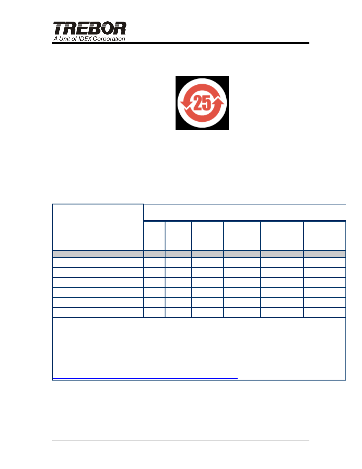
This equipment also complies with the requirements of the “Management
Methods for Controlling Pollution of Electronics Information Products”,
known as “China RoHS”.
Figure 1-2: China RoHS - Electronic information product pollution
control symbol
Trebor will use an EFUP (Environmental Friendly Use Period) of 25
years, which is consistent with the industry mean. The EFUP label is
located next to the main system nameplate and a declaration table is
included below.
Table [表]
PAGE 4 Q-SERIES DI HEATER OPERATION / MAINTENANCE MANUAL
Page 5

2 SAFETY
This section describes information that is important for safe equipment
operation. Included is a listing of message conventions used in this
manual, as well as equipment safety interlocks, push buttons, and labels.
The equipment described in this manual uses hazardous voltage
electricity that can be dangerous. Only personnel trained in the
procedures and safety messages outlined in this manual should install (if
applicable), operate, or maintain this equipment. Read and understand
this manual before installation or operation of the system. Follow all
recommended practices and procedures that apply to your actions and
conduct. All safeguard devices must be in place when equipment is in
operation. Operators, set-up operators, helpers or installation personnel
should not alter, remove or disable safety equipment. When using this
equipment, be sure to follow the safety procedures outlined by your
facility. These safety procedures should cover the two primary types of
hazard training: (1) equipment hazards and (2) facility-related hazards.
2.1 SAFETY MESSAGE CONVENTIONS
Safety messages contained in this manual; Dangers, Warnings, and
Cautions, are highlighted for quick identification.
2.1.a Danger
A Danger message indicates an imminently hazardous situation that, if
not avoided, will result in death or serious injury. Messages identified by
the word Danger are used sparingly and only for those situations
presenting the most serious hazards.
2.1.b Warning
A Warning message indicates a potentially hazardous situation that, if not
avoided, could result in serious injury. Following is a typical example of a
Warning message as it could appear:
Q-SERIES DI HEATER OPERATION / MAINTENANCE MANUAL PAGE 5
Page 6
Caution
Hot Surface
Do not touch. Can cause
skin burns upon contact.
Disconnect and lockout
power and allow surface to
cool before servicing.
2.1.c Caution
A Caution message indicates a potentially hazardous situation, which, if
not avoided, could result in minor or moderate injury. It may also be used
to alert against unsafe practices. Following is a typical example of a
Caution message as it could appear:
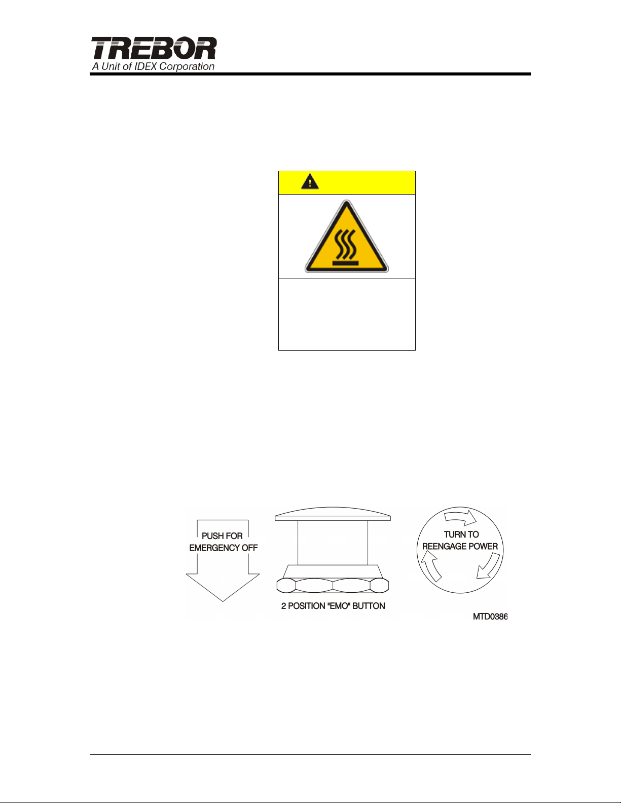
2.2 EMERGENCY OFF (EMO)
The EMERGENCY OFF button (EMO) is located on the front of the
heater. When the EMO circuit is activated by pushing the button in, the
equipment will be placed into a safe shutdown condition. The EMO will
de-energize the heaters and process interlock devices. Other devices on
the electrical panel remain energized and hazardous voltages will be
present at the power supply and power supply fuses, sub-panel circuit
breakers and contactors. Use the Main Power Disconnect Switch to
remove power altogether.
After the EMO button is disengaged, the heater must be reset by
pressing the blue RESET button located on the front of the heater near
the EMO button to reactivate the controls.
Figure 2-1
PAGE 6 Q-SERIES DI HEATER OPERATION / MAINTENANCE MANUAL
Page 7

Energy Type
Electrical
Hazard:
Electrocution, electrical burns, and shock
Magnitude:
480 VAC or 415 VAC or 380 VAC or 208 VAC
See system label for exact voltage.
Control Method:
Main Power
Shutdown Procedure
Switch off main circuit breaker disconnect handle at side of system.
2.3 LOCKOUT / TAGOUT
2.3.a Preliminary
Before installation or servicing the DI water heater, the facility’s power
source to the heater must be de-energized to prevent serious injury to
personnel and equipment. An authorized employee representing the
facility installing the DI water heater must follow approved company
guidelines and lockout or use suitable means to prevent re-energizing the
electrical system during installation or servicing.
2.3.b Definitions
Lockout: the placement of a lockout device on an energy isolating
device, in accordance with established company procedures, ensures
that the energy isolating device and the equipment being controlled
cannot be operated until the lockout device is removed.
Tagout: a prominent warning device such as a tag and a means of
attachment, which can be securely fastened to an energy isolating device
in accordance with established company procedure, ensures that the
energy isolated device and the equipment being controlled may not be reenergized or operated until the tagout device is removed.
This table lists the Lockout/Tagout information for the system.
2.3.c Machine Lockout with access panels installed
Perform the following sequence of events in the order listed for electrical
energy isolation of the tool:
1. Notify personnel in the area that you are going to shut down the
equipment.
2. Shutdown the system in an orderly fashion.
3. Locate the main incoming power disconnect switch-actuating handle.
4. Move the actuating handle to the "OFF" (down) position.
Q-SERIES DI HEATER OPERATION / MAINTENANCE MANUAL PAGE 7
Page 8

5. Apply the locking energy isolation device (lock) through the hole in the
actuating handle and secure the lock.
6. Verify that the tool has been isolated and de-energized by attempting
to turn the main power disconnect back to the “ON” position and/or by
pressing the machine start button. The machine power must not be
reapplied and/or the machine must not start.
2.3.d Machine Start-Up with access panels installed
Perform the following sequence of events in the order listed for electrical
re-energization of the tool:
1. Ensure that all hand tools are removed from the equipment and that it
is ready for start-up.
2. Notify personnel in the area that you are going to start-up the
equipment.
3. Open the lock and remove the locking energy isolation device (lock)
from the hole in the actuating handle of the Main Disconnect Switch.
4. Move the actuating handle to the "ON" (up) position.
5. Press the machine start button. The machine should start.
2.3.e Machine Lockout with access panels removed
Perform the following sequence of events in the order listed for electrical
energy isolation of the tool:
1. Notify personnel in the area that you are going to shut down the
equipment.
2. Shutdown the system in an orderly fashion.
3. Locate the main incoming power disconnect switch-actuating handle.
4. Rotate the rotary disconnect shaft to the "OFF" of “0” (down) position.
5. Insert key and lock the rotary disconnect lock located at the top left of
rotary disconnect device (see Figure 2-2). Remove the key.
6. Verify that the Tool has been isolated and de-energized by attempting
to turn the rotary disconnect shaft back to the “ON” or “1” position
and/or by pressing the machine start button. The machine power
must not be reapplied and/or the Machine must not start.
2.3.f Machine Start-Up with access panels removed
Perform the following sequence of events in the order listed for electrical
re-energization of the tool:
1. Ensure that all hand tools are removed from the equipment and that it
is ready for start-up.
2. Notify personnel in the area that you are going to start-up the
equipment.
PAGE 8 Q-SERIES DI HEATER OPERATION / MAINTENANCE MANUAL
Page 9
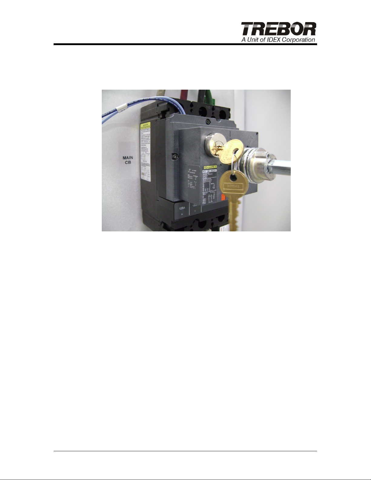
3. Insert key and unlock the rotary disconnect lock located at the top left
of rotary disconnect device (see Figure 2-2). Remove the key.
4. Move the rotary disconnect shaft to the "ON" of “1” (up) position.
5. Press the machine start button. The machine should start.
Figure 2-2: Lockout Key Location on Main Breaker
2.4 SEISMIC PROTECTION
It is the user’s responsibility to adequately secure and anchor the
equipment to comply with local regulatory agency seismic requirements.
Mounting holes for anchors are provided at the bottom of the cabinet
enclosure. See Facility Layout in Appendix for mounting hole locations.
Q-SERIES DI HEATER OPERATION / MAINTENANCE MANUAL PAGE 9
Page 10
3 INSTALLATION
3.1 UNPACKING
Remove heater system from crate and inspect heater cabinet for any
signs of damage (dented panels, paint scratches, etc.). Shock indicators
on the heater cabinet should be checked for rough handling during
shipment. Any damage to the system should be reported to the carrier
immediately.
CAUTION: Heavy Object. When lifting or moving the system,
follow safe heavy object handling methods to prevent injury.
Be careful to not damage the fittings located on back of heater cabinet
when using a dolly or forklift.
3.2 LOCATION
Locate the heater near the point-of-use to reduce plumbing heat loss.
Access to the side access panels will be necessary for maintenance and
utilities hook-up.
3.3 UTILITY HOOK-UP
All utility hook-ups associated with the DI water heater are easily
accessible and are referenced in the Appendix.
After positioning heater at operating location, adjust the four leveling feet
until the heater is level and stable.
Connect the cold DI supply line to the “Cold DI Inlet” connection.
Connect the hot DI process lines to the “Hot DI Outlet” connection.
Use only hot DI compatible plumbing components. They must be
rated at a minimum of 110°C (230°F) and 414kPa (60 psig).
NOTE: It is recommended that the hot water supply line have a bleed, or
purge, at the point-of-use to reduce the possibility of stagnating the DI
water in the heaters when not in use. The amount of this bleed is best
evaluated on a case-by-case basis, taking into account each user’s
criteria and production standards.
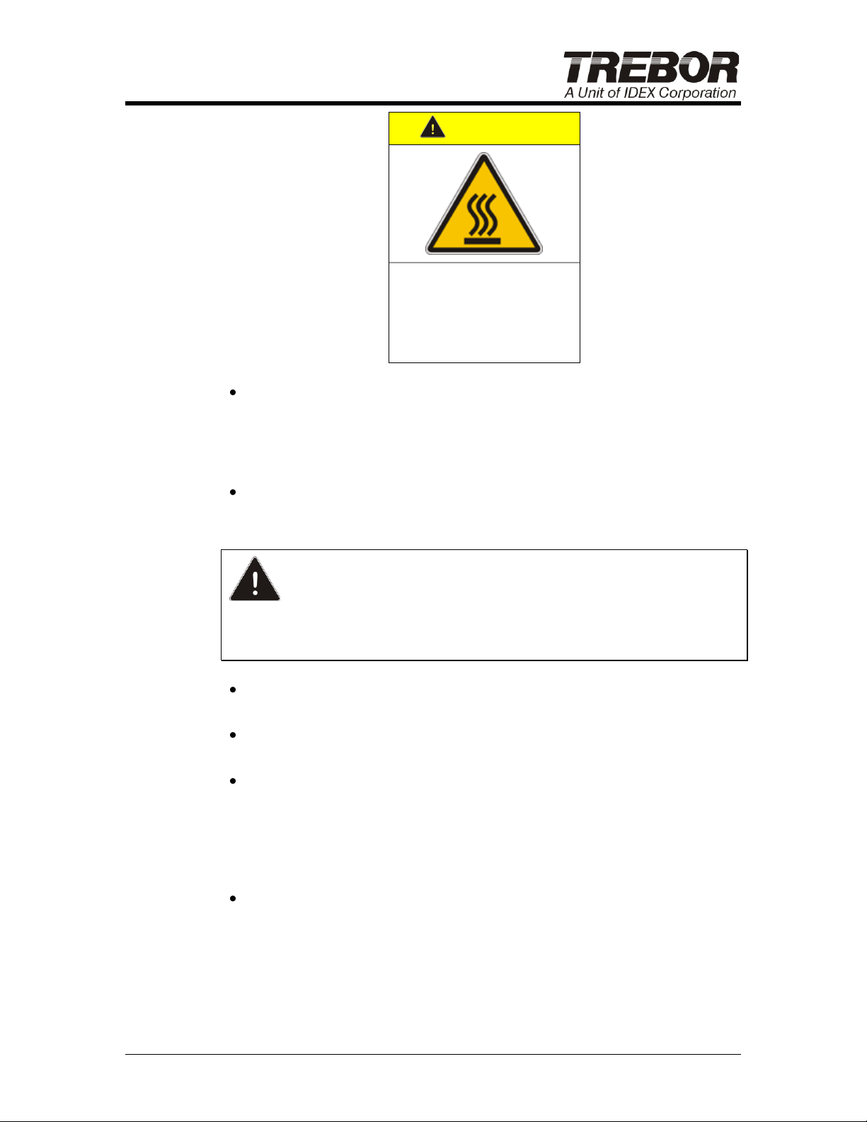
Recommendation: Either insulate the hot DI water process line or
place a Hot Surface hazard warning (shown below) on the tubing
every 20 feet. Conform to local codes while evaluating hot water line
routing.
PAGE 10 Q-SERIES DI HEATER OPERATION / MAINTENANCE MANUAL
Page 11
Caution
Hot Surface
Do not touch. Can cause
skin burns upon contact.
Disconnect and lockout
power and allow surface to
cool before servicing.
Connect the “Over Pressure Relief Drain” to an open drain line with
no more than 30’ of ¾” tubing. Do not connect restrictive fittings or
valves in line with the drain. If an overpressure condition occurs in
the heater, a burst fitting will relieve pressure in the heater. The fitting
is non-resettable and must be replaced if ruptured (see Section 8.1.f).
Attach cabinet drain line to bottom of cabinet. If a cabinet drain line is
not installed, the system will be difficult to drain should repairs be
needed.
CAUTION: Depending on installation and routing of water supply
lines, a trip hazard may be created. It is the responsibility of the facility
installation personnel to eliminate or minimize any and all trip hazards or
identify such hazards with visual warning signs.
Lockout and Tagout facility power connection switch or equivalent
before connecting power lines to heater main breaker.
To access the electrical cabinet, rotate the electrical disconnect
handle to the “OFF” position and then remove the side access panel.
Route the wires from the electrical source (480 VAC, 415VAC, 380
VAC, or 208 VAC 3-phase) into and through the conduit opening on
the top of the enclosure. To secure an electrical conduit fitting,
remove lifting eyebolts located on top of the system and raise the
vented top panel. The conduit nut may then be secured. Reassemble
the vented top panel to the enclosure.
Connect the supply grounding wire to the grounding lug and the other
three lines into the top of the circuit breaker connections (L1, L2, and
L3) as shown in Figure 3-1 (torque wire terminal connections to 120
in/lb).
Q-SERIES DI HEATER OPERATION / MAINTENANCE MANUAL PAGE 11
Page 12
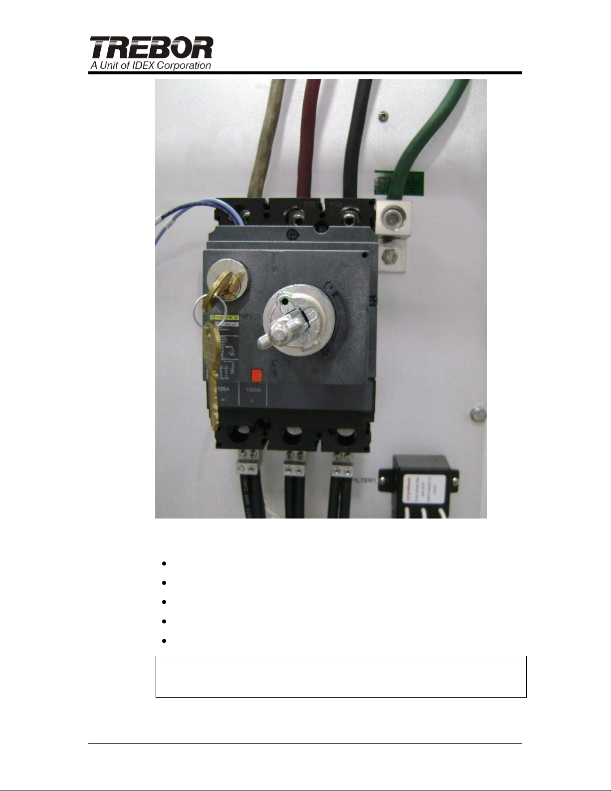
Figure 3-1
Install access panel.
Check ground continuity on cabinet to any facility ground.
Remove Facility power Lockout/Tagout.
Restore Facility power supply to the heater.
Follow heater Pre-Start Inspection (see Section 4.1).
NOTE: Before starting the system, it is important to become familiar with
Sections 4 and 5. Only trained, qualified, authorized, personnel should
operate this system.
PAGE 12 Q-SERIES DI HEATER OPERATION / MAINTENANCE MANUAL
Page 13

4 START-UP
4.1 PRE-START INSPECTION
This Trebor DI Water Heater has been thoroughly tested and inspected
for proper performance and operation prior to leaving the factory.
Additional pre-start inspection can identify any damage or condition
change that may have occurred during shipment of the heater and
reduce nuisance problems during start-up.
4.1.a Verify Shipping Condition
Refer to Section 3.1, Unpacking.
4.1.b Hazardous Power Terminals
Refer to PM Schedule, Section 8.2. Tighten hazardous power
connections at the main circuit breaker, distribution circuit breakers,
distribution contactors and SSRs. Slightly loose connections at these
hazardous power terminals can cause arcing. This arcing can introduce
higher than normal operating temperatures, resulting in damage of
electrical components. Tighten terminal in a clockwise direction only.
Do not loosen terminals before tightening as this may affect the contact
area.
4.1.c Electrical Inspection
Refer to system schematic. Visually inspect all electrical components for
anything that seems unusual, such as damaged wire insulation,
disconnected wires, etc.
4.1.d Plumbing Leak Check
Refer to PM Schedule, Section 8.2. Inspect heater for leaks during
start-up. Open the plumbing access panel and visually watch the leak
tray as the system is initially filled with water. Visually inspect heater
module fittings and heater system plumbing for leaks.
If leaks are found at the flare fittings, hand-tighten fittings while they
are at ambient temperature. Do not use a wrench to tighten flare
fittings, as excessive tightening can cause damage to the fittings.
If any problems are encountered during start-up of this heater, contact
Trebor for technical support.
Q-SERIES DI HEATER OPERATION / MAINTENANCE MANUAL PAGE 13
Page 14

4.2 SYSTEM POWER
Activate the power to the system by rotating the “Main Breaker” handle to
ON. If the display on the control panel does not illuminate, ensure that
the EMERGENCY OFF button is in the operate position.
4.3 HEATING WATER
Ensure minimum water pressure is provided at cold DI inlet, and then
press the blue RESET button located on the front of the heater near the
EMO. The power contactors will engage and the heater will be in standby
mode, ready to heat water. See instructions in section 5 for operating the
heater locally or remotely and for explanation of process interlocks.
PAGE 14 Q-SERIES DI HEATER OPERATION / MAINTENANCE MANUAL
Page 15

5 HEATER OPERATION
The Q-Series DI water heater is very easy to operate locally via a built-in
graphical user interface or remotely through an external hardware
interface. Simply choose a temperature set point and let the controls do
the rest.
If the heater encounters a problem, the on-board controller will notify the
operator that the heater requires attention (see section 6 for details of
system interlocks). After the fault condition is corrected, the heater can
be reset using the blue RESET button located on the front of heater to
resume normal operation.
This section outlines the detailed instructions for operating the heater
locally and remotely.
5.1 BACKGROUND COLOR CONVENTIONS FOR BUILT-IN
GRAPHICAL USER INTERFACE
The graphical user interface displays the following background colors to
provide visual indication of the heater’s:
Green – OK status. All process interlocks are cleared and the heater is
ready to heat water.
Red – Fault status. A fault condition is present (see sections 5.2.b and 6).
The heater cannot heat water until the fault condition is cleared.
Orange – Emergency Off status (EMO). The EMO button on the heater
has been engaged.
Yellow or Light Green – Reset status. The blue RESET button on the
front of the heater must be pressed before the heater can heat water.
5.2 LOCAL OPERATION THROUGH BUILT-IN GRAPHICAL
USER INTERFACE
A display panel located on the front of the heater provides an intuitive
graphical interface to the DI water heater. This interface is divided into
four pages which have been designed to be simple to use and easy to
understand. Buttons located at bottom of the display panel are used for
both navigating between screens and changing values for inputs such as
temperature set point. The following sections describe each page in the
graphical user interface in detail.
Q-SERIES DI HEATER OPERATION / MAINTENANCE MANUAL PAGE 15
Page 16
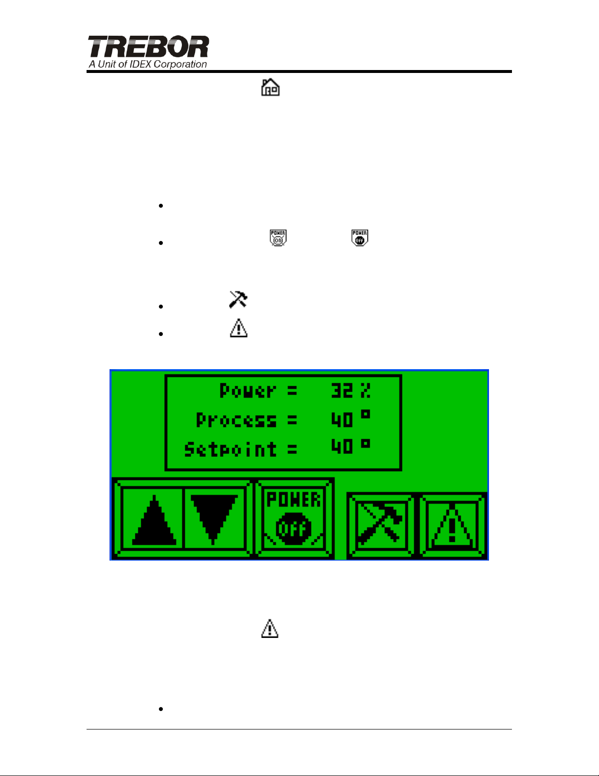
5.2.a Home Page
The Home page is the first page that is displayed after the system power
is enabled. This page is designed to show the current status of the
heater at a glance. The temperature set point (°C), process temperature
(°C), and power usage being applied to the heater outlet (%) are
displayed and buttons allow access to change the temperature set point
and to enable or disable the heating of water.
Buttons F1 and F2 will either increase (▲) or decrease (▼) the
Temperature Set Point value in 1°C increments.
Button F3 enables ( ) or disables ( ) the heating of water.
The following navigation buttons are also available for advancing to the
Configuration and Alarm pages:
Button F4 ( ) switches the display to the Configuration page
Button F5 ( ) switches the display to the Alarm page
F1 F2 F3 F4 F5
Figure 5-1: Home Page
5.2.b Alarm page
The alarm page displays the status of all process interlock alarms (see
section 6 for details of process interlocks). The following list explains the
items on the Alarm Screen:
Pressure = Status of the low fluid pressure interlock
PAGE 16 Q-SERIES DI HEATER OPERATION / MAINTENANCE MANUAL
Page 17
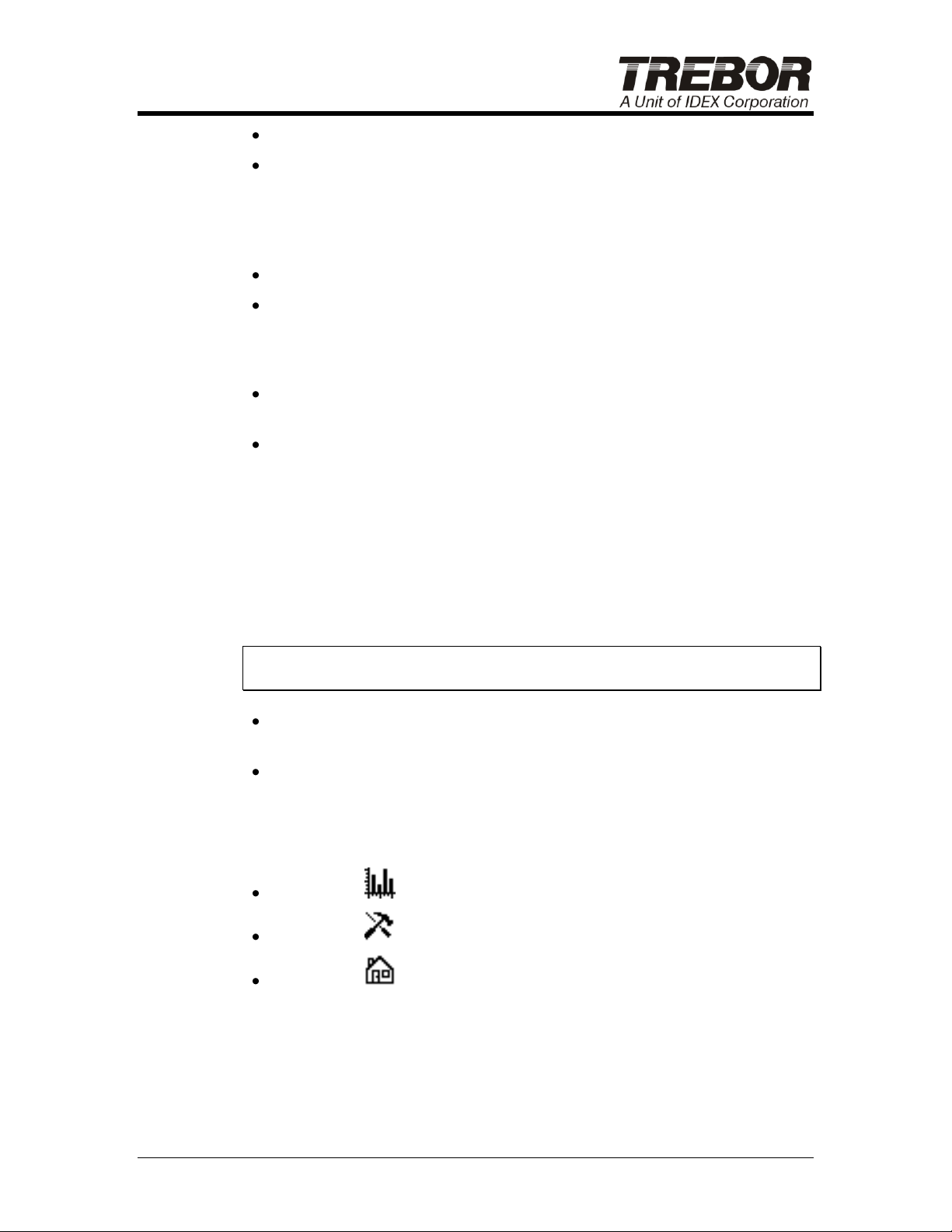
LiqLeak = Status of Liquid Leak interlock inside heater
OverTemp = Status of Over-Temperature Limit interlocks. Each
heater has one temperature limit sensor on the quartz substrate and
one temperature limit sensor on each of the heating elements. An
over-temperature condition detected by any of these sensors will be
reported by the OverTemp alarm
LiqLevel = Status of Liquid Level interlock
TC Error = Status of thermocouples. This alarm is activated if any of
the thermocouples report an “open” condition.
Alarm status will be shown in the following states:
Alarm Ok – All interlocks are clear and heater is able to operate
normally.
Alarm Delay – The pressure and liquid level interlocks wait a certain
period of time before putting the system into an alarm state. This
delay is intended to eliminate alarm activation and system shutdown
due to instantaneous fluctuations in fluid pressure and liquid level.
During this period the heater is put in a safe state while waiting for the
fault condition to clear and the alarm will be reported in the Alarm
Delay state. If fault condition is corrected before the timeout period
elapses, the heater will go back to normal operation without alarming.
If the fault condition is not corrected before the timeout period
expires, the heater will progress to an alarm state.
NOTE: The default timeout period is 30 seconds. Contact factory for
instructions on how to adjust this time delay.
Alarm Active – A fault condition has initiated an alarm state and the
fault has not yet been corrected.
Alarm On – A fault condition has initiated an alarm state but the fault
has already been corrected.
The following navigation buttons are also available for advancing to the
Plot, Configuration and Home pages:
Button F3 ( ) switch the display to the Plot page
Button F4 ( ) switches the display to the Configuration page
Button F5 ( ) switches the display to the Home page
Q-SERIES DI HEATER OPERATION / MAINTENANCE MANUAL PAGE 17
Page 18
„High Flow‟ PID Settings
„Low Flow‟ PID Settings
# Mod, Power
High Flow (GPM)
Low Flow (GPM)
High Flow (GPM)
Low Flow (GPM)
3, 36kW
1.6
0.5
0.6
0.1
6, 72kW
3.25
1.3
1.75
0.25
12, 120kW
5.4
2.1
3.0
0.5
12, 144kW
6.5
2.6
3.5
0.5
F1 F2 F3 F4 F5
Figure 5-2: Alarm Page
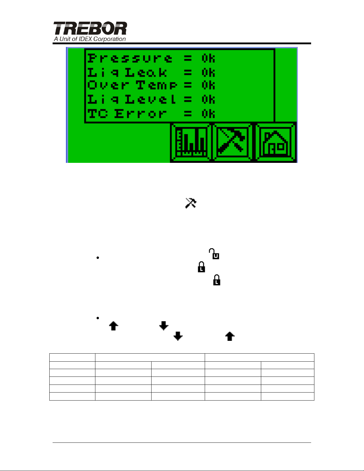
5.2.c Configuration Page
The Configuration page is used to change the method for communicating
to the heater and to select optimal PID settings for high flow or low flow
operating conditions.
Button F1 enables local operation ( ) through the graphical user
interface or remote operation ( ) through an external hardware
interface. When remote operation ( ) is selected, the temperature
set point cannot be adjusted nor can the heating of water be enabled
or disabled locally through the display panel as described in section
5.2.a.
Button F2 enables the optimal preset PID configuration for High flow
( ) or Low flow ( ) conditions. Refer to Table 5-1 when deciding
to select the Low flow ( ) or High flow ( ) configuration during
critical process steps.
PAGE 18 Q-SERIES DI HEATER OPERATION / MAINTENANCE MANUAL
Table 5-1: Flow Settings
The following navigation buttons are also available for advancing to the
Home and Alarm pages:
Page 19
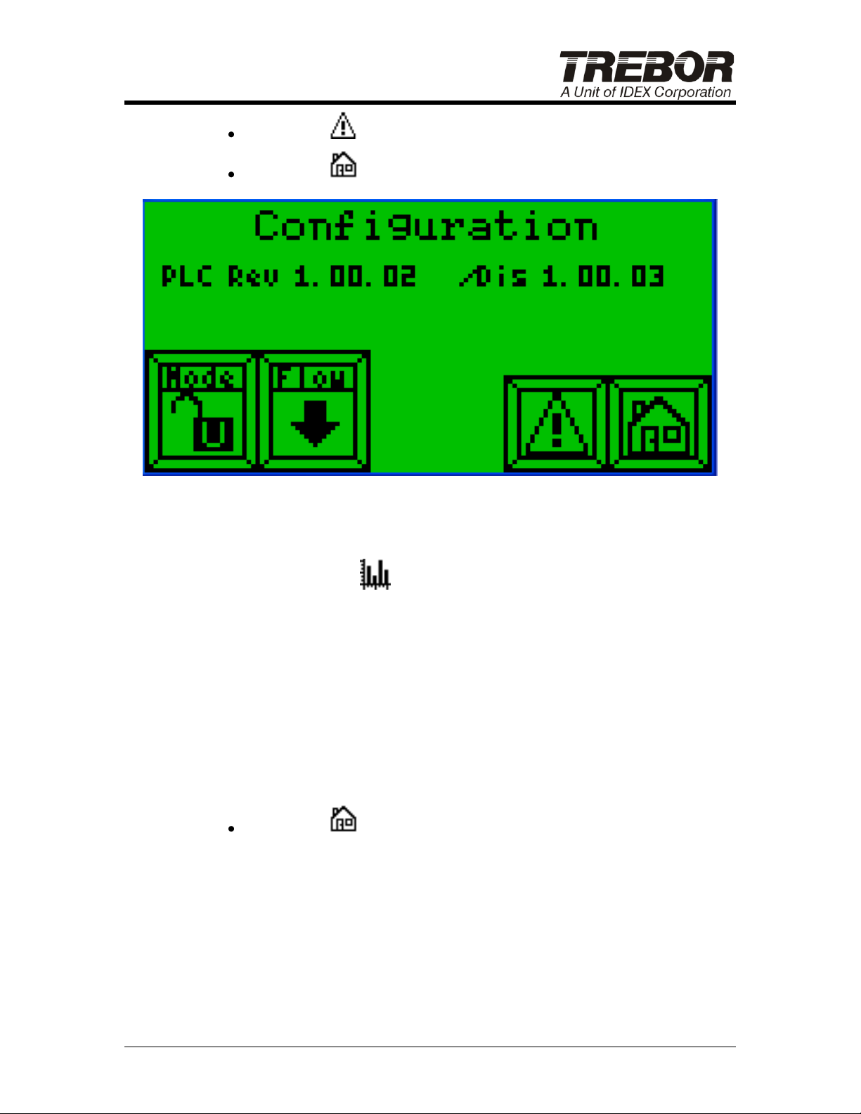
Button F4 ( ) switches the display to the Alarm page
Button F5 ( ) switches the display to the Home page
F1 F2 F3 F4 F5
Figure 5-3: Configuration Page
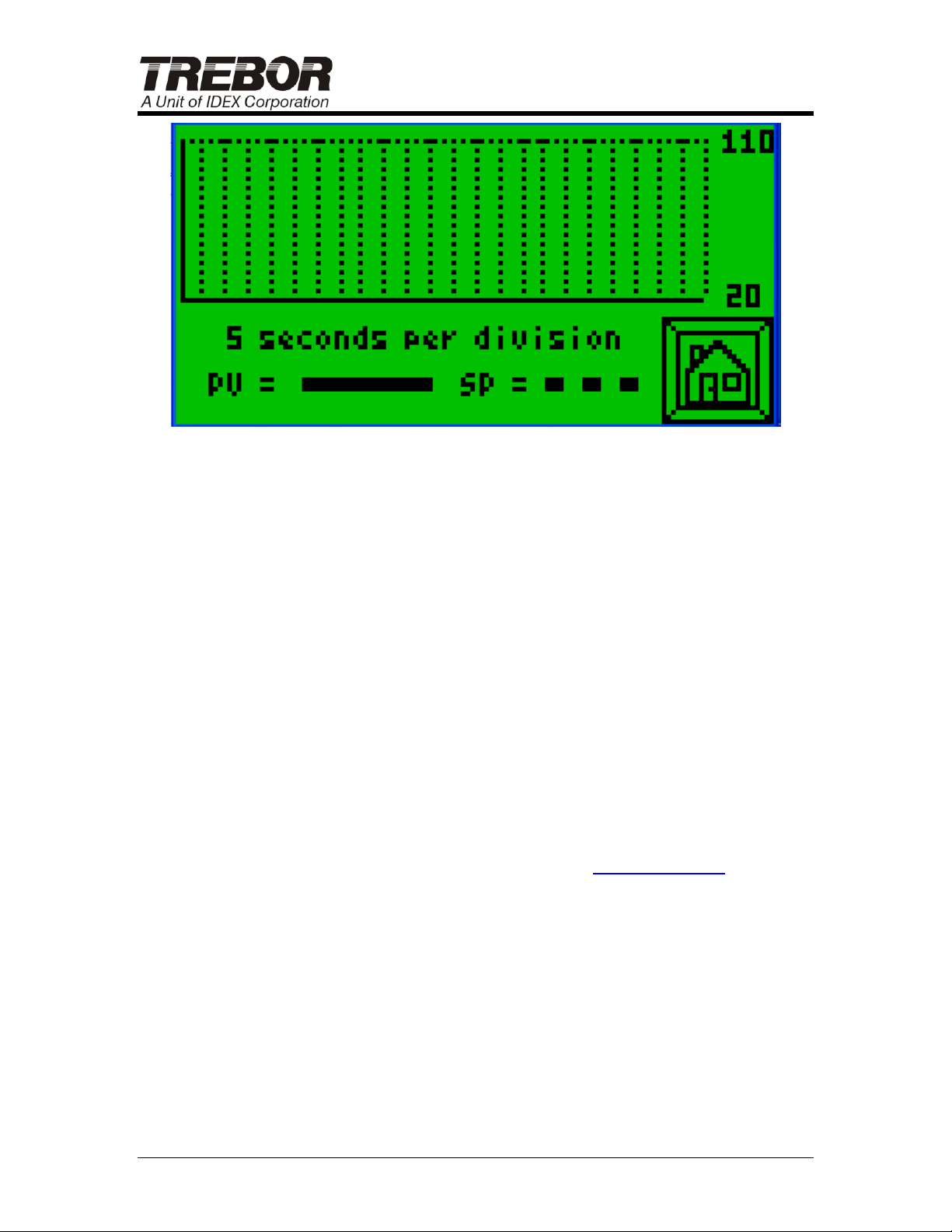
5.2.d Plot Page
The Plot page is used to observe the status change of the process
temperature (PV with solid line) with relationship to the set point value
(SP with dashes) during 2 minutes of time in 5 second intervals. The plot
time starts when the page is entered and will only continue while the plot
page is selected. Whenever the plot page is exited and returned, the plot
will again start plotting. The plot page will not continue to plot when not
on the plot page. Why? That is how the plot works in the display unit.
The only navigation button defined on this page is to return to the Home
page:
Button F5 ( ) switches the display to the Home page
Q-SERIES DI HEATER OPERATION / MAINTENANCE MANUAL PAGE 19
Page 20
F1 F2 F3 F4 F5
Figure 5-4: Plot Page
5.3 REMOTE OPERATION OVER AN EXTERNAL HARDWARE
INTERFACE
When the system is in the remote operation mode (see section 5.2.c) the
heating of water can be enabled or disabled, the temperature set point
can be adjusted and monitored, and the status of alarms can be
monitored remotely over an external hardware interface; however, the
temperature set point cannot be adjusted nor can the heating of water be
enabled or disabled locally through the display panel as described in
section 5.2.a.
5.3.a Remote Communication via Modbus/RTU
The default remote operation communication protocol is Modbus/RTU
over an RS232 hardware interface. See Table 5-2, for the heater’s
register and coil address mapping. For information regarding the
Modbus communication protocol please visit www.modbus.org.
PAGE 20 Q-SERIES DI HEATER OPERATION / MAINTENANCE MANUAL
Page 21
Name
Address
Type
Data
Bytes
Perm
Value
Alarm Status
003075
Coil
Bool 1 R
0-1
Alarm Pressure
003081
Coil
Bool 1 R
0-1
Alarm Pressure Status
400641
Reg
Short 2 R
1-4
Alarm Liquid Leak
003082
Coil
Bool 1 R
0-1
Alarm Liquid Level
003084
Coil
Bool 1 R
0-1
Alarm Liquid Level Status
400644
Reg
Short 2 R
1-4
Alarm Over Temp
003083
Coil
Bool 1 R
0-1
Alarm Thermocouple
003085
Coil
Bool 1 R
0-1
Flow Range
003111
Coil
Bool 1 RW
0-1
Percent Power
400671
Reg
Short 2 R
0-100(%)
Process Temperature
400778
Reg
Short 2 R
0-120(°C)
Remote heater Power
003112
Coil
Bool 1 RW
0-1
Remote Mode
003113
Coil
Bool 1 R
0-1
Remote Set Point
400786
Reg
Short
2
RW
10-95(°C)
Table 5-2: Modbus Address Mapping
For example:
To enable the heating of water, a write request must be sent to the
address for the “Remote Heater Power” coil with a value of 1.
To disable the heating of water, a write request must be sent to the
address for the “Remote Heater Power” coil with a value of 0.
To monitor the temperature set point, a read request must be sent to
the address for the “Remote Set Point” register.
To adjust the temperature set point, a write request must be sent to
the address for the “Remote Set Point” register with a value between
15 and 95.
Q-SERIES DI HEATER OPERATION / MAINTENANCE MANUAL PAGE 21
Page 22
6 PROCESS INTERLOCKS
The heater is equipped with multiple process fault interlocks to ensure
safe and reliable operation. When a fault is detected the graphical user
interface will change display color (see section 5.1) and indicate the
alarm condition (see section 5.2.b), an audible horn will sound, and power
to the heater modules will be disabled. Pressing the blue RESET button
on the front of the heater will silence the audible horn. After the fault
condition is corrected, the heater can be reset using the blue RESET
button located on the front of heater to resume normal operation.
A troubleshooting guide is included in section 9 to help diagnose and
correct common fault conditions.
CAUTION: The interlock circuit does not remove hazardous
voltage from the circuit breakers, contactor, and the control transformer.
Only authorized, qualified, trained personnel should service this
equipment.
6.1 LOW FLUID PRESSURE SENSOR
If the fluid pressure decreases below 103 kPa (15 psig) the low fluid
pressure interlock will immediately disable the ability to heat water but will
wait a certain period of time before putting the system into an alarm state.
This delay is intended to eliminate alarm activation and system shutdown
due to instantaneous fluctuations in fluid pressure. During the delay
period the heater is put in a safe state while waiting for the fluid pressure
to increase above 103 kPa (15 psig). If the fluid pressure increases
above 103 kPa (15 psig) before the delay period elapses, the heater will
go back to normal operation without alarming. If the fault condition is not
corrected before the delay period expires, the heater will progress to an
alarm state (see section 5.2.b).
NOTE: The default timeout period is 30 seconds. Contact factory for
instructions on how to adjust this time delay.
6.2 LIQUID LEVEL SENSOR
If the water level is insufficient to fill the heating modules, the liquid level
interlock will immediately disable the ability to heat water but will wait a
certain period of time before putting the system into an alarm state. This
delay is intended to eliminate alarm activation and system shutdown due
to instantaneous fluctuations in liquid level. During the delay period the
heater is put in a safe state while waiting for the fault condition to be
corrected. If the liquid level returns to an appropriate level before the
delay period elapses, the heater will go back to normal operation without
PAGE 22 Q-SERIES DI HEATER OPERATION / MAINTENANCE MANUAL
Page 23
alarming. If the fault condition is not corrected before the delay period
expires, the heater will progress to an alarm state (see section 5.2.b).
NOTE: The default timeout period is 30 seconds. Contact factory for
instructions on how to adjust this time delay.
The liquid level interlock utilizes an optical sensor to detect water level. It
is critical that this sensor operate properly. Do not tamper with the
sensor. Damage to the system can result if the sensor is altered.
6.3 ELEMENT OVER TEMPERATURE SENSOR
A temperature limit controller monitors a thermocouple attached to a
heater element in each of the heater modules. In the event an element
temperature exceeds the normal operating temperature, the ability to
heat water will immediately be disabled and the system will go into an
alarm state. If this occurs, check element continuity before continuing
normal operation (see section 8.1.a).
NOTE: Running the heater at the maximum temperature set point and at
a flow rate that requires 100% power for extended periods can lead to
intermittent over temperature alarms. Reducing flow or temperature set
point slightly will correct the problem.
6.4 LIQUID LEAK SENSOR
If a liquid leak is detected in the bottom of the heater cabinet, the ability
to heat water will immediately be disabled and the system will go into an
alarm state. Fix any leaks and dry the leak sensor and leak tray prior to
turning power on to the system.
6.5 OVERPRESSURE RELIEF FITTING
The overpressure relief fitting “Relief Drain” is connected in-line with the
cold DI inlet port to provide a mechanical safeguard against possible
damage from operating the heater with a fluid pressure above 414 kPa
(60 psig).
If the overpressure relief device opens, the low fluid pressure sensor will
alarm. A periodic visual inspection of the fitting is recommended. Refer
to Section 8.1.f for instructions on replacing the relief fitting.
Q-SERIES DI HEATER OPERATION / MAINTENANCE MANUAL PAGE 23
Page 24

7 SYSTEM SHUT DOWN
The DI water heater may be shut down by the following methods:
Select the OFF button on the display panel to put the heater in
standby (heater element power will be disengaged).
Rotate “Main Breaker” to off position.
Turn off the facility power supply.
Lockout and tagout heater for maintenance or repair. Refer to
Section 2.3.
PAGE 24 Q-SERIES DI HEATER OPERATION / MAINTENANCE MANUAL
Page 25
8 MAINTENANCE
8.1 REPAIR INSTRUCTIONS
Heater modules have a finite life. Spare heating modules should be on
hand in case of a failure.
NOTE: If top element fails then switch off circuit breaker for lower
element to maintain consistent temperature control.
8.1.a Heater Element Check
If the heater is having difficulty maintaining set point, visually inspect the
main and auxiliary circuit breakers. Then check the corresponding
element isolation circuit breaker to see if it has tripped.
Check the continuity of the heating elements as follows:
Turn power off to system (see Section 2.3 for Lockout/Tagout
procedures).
Switch off the element circuit breakers in the control enclosure.
Check for continuity between the two screw terminals on the left of
the breaker for each pair of element circuit breakers.
If no continuity exists, replace the suspect heater modules; see
Section 8.1.b Heater Replacement.
If there is continuity, then the heater element is OK. Refer to the
Troubleshooting Section of this manual for other possible causes.
8.1.b Heater Replacement
The heater modules have been designed for quick replacement to
minimize downtime and field service requirements. To replace a heater
module, follow these procedures:
Turn power off to system (see Section 2.3 for Lockout/Tagout
procedures).
Drain system (see Section 8.1.d, Draining the System).
Remove the side panel of the enclosure to access heater modules.
Disconnect the electrical connector to the failed module.
Remove steel band clamps connecting heater module to cabinet, but
do not remove clamps used to connect the electrical box to the
module housing
Loosen fluid inlet and outlet fittings on module.
Q-SERIES DI HEATER OPERATION / MAINTENANCE MANUAL PAGE 25
Page 26
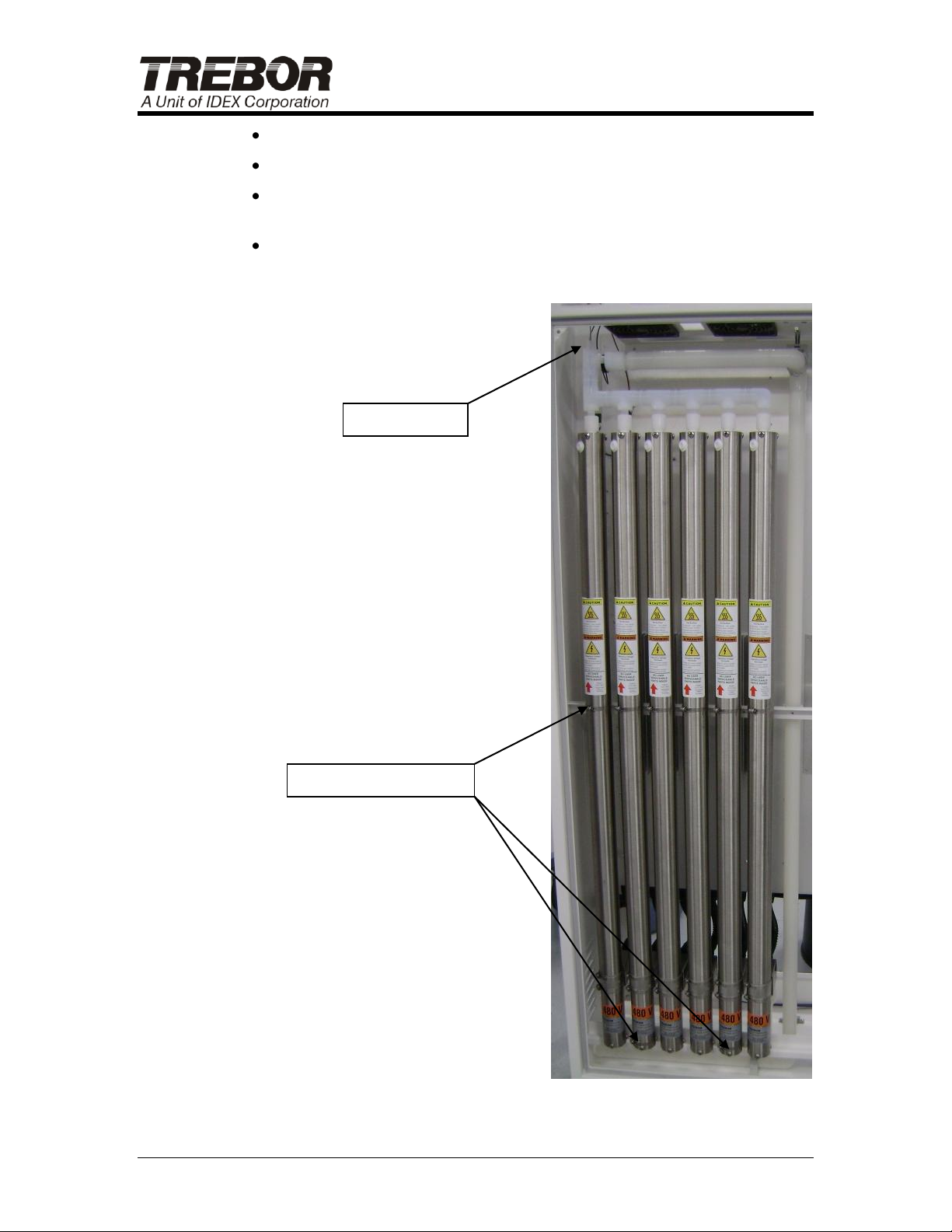
Process T/C
Heater Band Clamps
Disengage the inlet fitting by sliding the bottom of heater off shelf.
Lower the heater to disengage top fitting from manifold.
Use an absorbent cloth to remove any liquid from the leak sensor
probe and leak containment well.
Install replacement heater module into cabinet in reverse order from
above. Note: Carefully align the fluid fittings because they can easily
be cross-threaded.
PAGE 26 Q-SERIES DI HEATER OPERATION / MAINTENANCE MANUAL
Figure 8-1
Page 27
NOTE: Do not disassemble the heater module. There are no user
serviceable parts inside the module. If disassembled, any product
warranties will be invalid.
8.1.c Liquid Level Sensor Calibration
Contact factory for calibration instructions.
8.1.d Draining the System
Connect fluid inlet to an open drain line. (Alternate: If a drain line is
connected to the cabinet drain on the bottom of the heater enclosure,
the heater may be drained into the leak tray.)
Loosen a fitting in the upper manifold to release internal vacuum in
fluid lines.
The system will drain through the cold DI inlet; a small amount of
water will drain through fluid exit port.
Perform required maintenance.
Reconnect fluid inlet and outlet to process lines and refill the system.
8.1.e Leaks
When a leak has been detected it is recommended that the supply water
be shut off along with the main circuit breaker. Allow sufficient time for
the heater and plumbing to cool down before inspection.
NOTE: If water is leaking out of the heater module shroud a replacement
module will be required.
Q-SERIES DI HEATER OPERATION / MAINTENANCE MANUAL PAGE 27
Page 28
Initial
Start
Weekly
6 Months
Items
Visually
Inspect
Tighten
X X
Process Control / Heater Element Status
X X X
Plumbing Leaks
X X X
Overpressure Relief Drain & Diaphragm
X X X
General Electronics
X X X
Solid State Relays (SSR’s)
X X X
Main Circuit Breaker
X X X
Distribution Breakers & Contactors
X X X
Branch Circuit Breakers
X
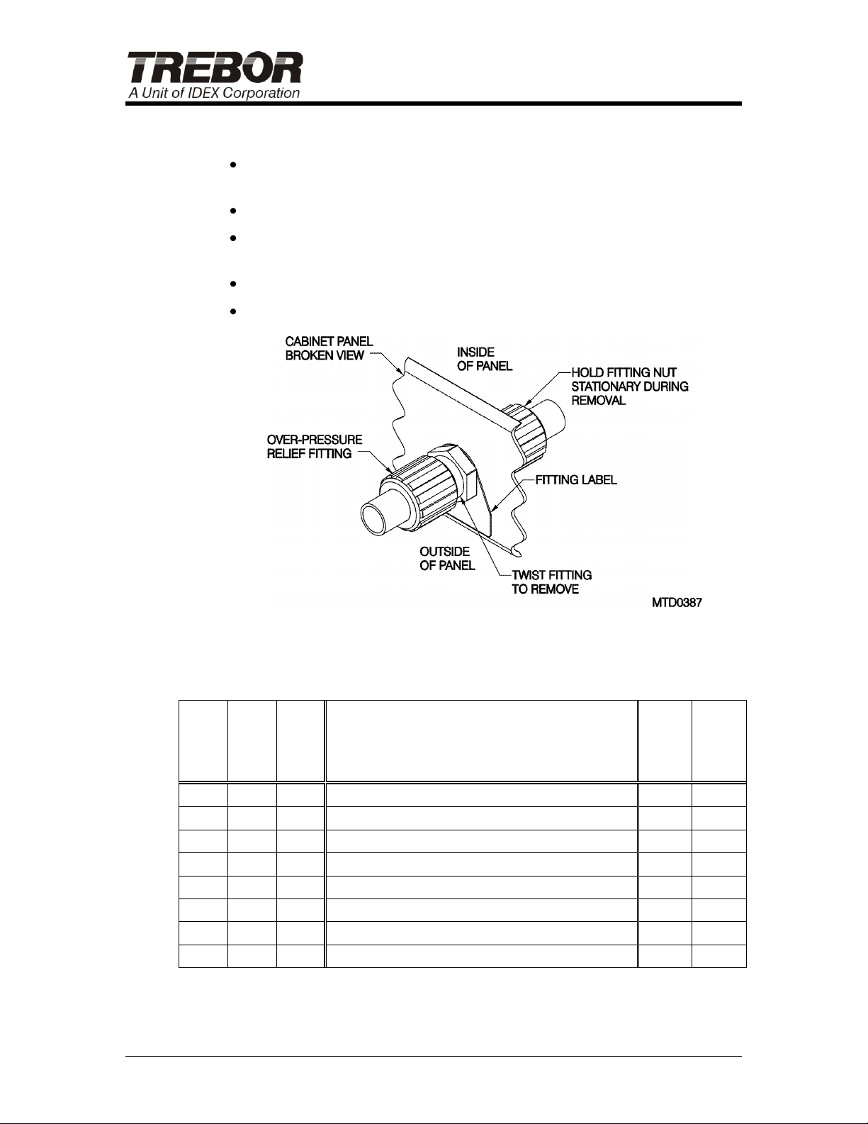
8.1.f Overpressure Relief Fitting Replacement
Turn power off to system (see Section 2.3 for Lockout/Tagout
procedures).
Drain system (see Section 8.1.d, Draining the System).
Remove and replace overpressure relief fitting (note orientation of
fitting).
Refill system.
Inspect for leaks.
Figure 8-2
8.2 PREVENTIVE MAINTENANCE SCHEDULE
See following table for details on each item.
PAGE 28 Q-SERIES DI HEATER OPERATION / MAINTENANCE MANUAL
Page 29
ITEM
DETAILS
Plumbing
Leaks
Visually check DI water lines outside of heater cabinet for signs of leaks at the
connections. (A leak sensor will detect leaks, but this periodic visual check is
recommended.) Also, visually check bottom of cabinet inside heater module
enclosure for DI water leaks. Tighten fitting(s) if necessary. If heater module
is leaking, contact Trebor for instructions.
Overpressure
Relief Drain &
Diaphragm
Visually check the drain line for water running from the heater. The
overpressure burst fitting can start leaking if the system has experienced
pressures above 60 PSIG. The burst fitting can be checked by inspecting the
relief port at the back of the cabinet. No water should be present in the relief
drain since it is required to be plumbed to an open drain. If water is present in
the drain plumbing, the fitting should be replaced.
General
Electronics
Visually check electronics inside control enclosure for any signs of
overheating, deformation, or corrosion.
Solid State
Relays
The SSR’s should be free of corrosion at the terminals and should not have
signs of overheating or deformation. The wires attached to the SSR’s should
be clean and in good condition. Check and tighten mounting screws for
optimum heat transfer to heatsink.
Main Circuit
Breaker
The main circuit breaker should be checked for signs of loose connections at
the termination lugs. Damaged lugs should be replaced. The terminals should
be checked for tightness.
Distribution
Breakers &
Contactors
The distribution breakers and contactors should be checked for signs of loose
connections at termination lugs. Damaged lugs should be replaced. The
terminals should be checked for tightness.
Branch
Circuit
Breakers
These should be checked for signs of loose connections at the termination
lugs. The terminals should be checked for tightness.
Label
Part
Number
Description
Torque Value
MCB1
Circuit Breaker, 3 Pole, 480VAC, 60-225A
26.0 Nm / 230.1 in-lb
MCB1
98003859
Connection Terminal Block, 6 Wire, 14-6AWG
6.0 Nm / 53.1 in-lb
CB1-4
98003862
Circuit Breaker, 3 Pole, 480VAC, 50A
5.6 Nm / 49.6 in-lb
CONT 1-4
98003864
Contactor, 50A, 400V, 3 Pole, 24VDC
2.5 Nm / 22.1 in-lb
SSR 1-8
98004141
SSR, 125A, 4-32VDC
3.7 Nm / 32.7 in-lb
CBH 1E1-12E2
98003865
Circuit Breaker, 2 Pole, 480VDC, 15A
2.5 Nm / 22.0 in-lb
CB5
98003867
Circuit Breaker, 1 Pole, 480VAC, 3A
2.5 Nm / 22.0 in-lb
CB6
98003866
Circuit Breaker, 3 Pole, 480VAC, 6A
2.5 Nm / 22.0 in-lb
24VDC-PS
98003781
Power Supply, 10A, 320-575VAC, 3 Phase
0.6 Nm / 5.3 in-lb
TLM 1
98004131
16 Channel Temperature Controller
0.4 Nm / 3.1 in-lb
98003505
Connection Block, NO, 24VDC
0.8 Nm / 7.1 in-lb
98003520
Connection Block, NC, 24VDC
0.8 Nm / 7.1 in-lb
Verify torque at least every 6 months with a calibrated torque wrench. Do
not over tighten. Consult factory with questions.
Q-SERIES DI HEATER OPERATION / MAINTENANCE MANUAL PAGE 29
Page 30

Display is Not Illuminated
Cause:
Solution:
No power at main circuit breaker
Review wiring procedure (see Section 3, Installation).
Control breaker is blown
Check breaker.
Main breaker is OFF
Turn Main breaker to ON.
Alarm Sounds
Cause:
Solution:
DI supply pressure low
Check water supply pressure at source.
Liquid level low
Check water supply at source.
Check overpressure relief diaphragm for rupture.
Check fluid lines in and out of manifold for flow.
Liquid leak
Check manifold and heater modules for leak. Visually
inspect leak tray.
Thermocouple damaged
Check thermocouple leads at temperature limit controller
for continuity.
Over-temperature alarm
Check if heater element has failed and replace module
(see section 8.1).
Check thermocouple leads at temperature limit controller
for continuity.
Verify fan operation.
Unable to maintain set point
Cause:
Solution:
Failed heater element
Circuit breaker tripped
Check if heater element has failed and replace module
(see Section 8.1).
Check and reset the main, auxiliary and element isolation
circuit breakers.
Consult Trebor if circuit breaker repeatedly trips.
Solid State Relay (SSR) may have
“frozen” open
An SSR has failed in the open mode: Shut system off
immediately and replace the failed SSR. SSR’s should be
replaced in pairs.
9 TROUBLESHOOTING
PAGE 30 Q-SERIES DI HEATER OPERATION / MAINTENANCE MANUAL
Page 31

10 WARRANTY
See the Trebor Standard Limited Warranty at
http://www.treborintl.com/TechnicalSupport.aspx
Q-SERIES DI HEATER OPERATION / MAINTENANCE MANUAL PAGE 31
 Loading...