

Page 1
Phone: 800-669-1303 or 801-561-0303
Fax: 801-255-2312
e-mail: [email protected]
CHAMPION SL20
Slurry/Booster Pump
Operation / Maintenance
Manual
SERIAL NUMBER (located on top of product):
PATENTS: U.S. 09642426, U.S. 06106246, U.S. 05971402, U.S. 05370507 NOVEMBER, 2007 – MSL20-C
Page 2
CONTENTS
1 PREFACE.....................................................................................................................3
1.1 INTRODUCTION TO TREBOR SL20 SLURRY/BOOSTER PUMP ..................3
2 INSTALLATION............................................................................................................4
2.1 UNPACKING ......................................................................................................4
2.2 UTILITIES / HOOK-UP FOR CHAMPION SL20 PUMP.....................................4
2.3 UTILITIES / HOOK-UP FOR REMOTE CONTROLLER....................................5
2.3.a Trebor’s PC20 Electronic Oscillator ......................................................5
3 START-UP....................................................................................................................7
3.1 CONTROLLER OPERATION.............................................................................8
3.1.a The PLC outputs are shown in Table 2.................................................9
3.1.b Changing a pump function listed in Table 3:.........................................9
3.1.c Turning Pump On and Off ...................................................................10
3.1.d Auto Tune Mode..................................................................................10
3.1.e Manual Tune Mode (Auto Tune-OFF).................................................10
3.1.f Booster Mode......................................................................................11
3.1.g Preventative Maintenance (PM) Counter............................................11
3.1.h Changing PLC data stores listed in table 3:........................................11
3.1.i Tune Optics .........................................................................................12
3.2 PERFORMANCE CHARTS – PUMPING WITH INLET SUCTION REQUIRED12
3.3 PERFORMANCE CHARTS – BOOSTER PUMPING......................................13
4 MAINTENANCE .........................................................................................................15
4.1 PREVENTIVE MAINTENANCE SCHEDULE...................................................15
4.1.a Preventive Maintenance Record.........................................................17
4.2 RECOMMENDED SPARE PARTS ..................................................................18
4.3 TOOLS..............................................................................................................18
4.4 PARTS ILLUSTRATION...................................................................................19
4.5 PARTS LIST.....................................................................................................20
4.6 CONTROLLER PARTS LIST – PC20..............................................................21
4.7 CLEAN-UP........................................................................................................21
4.8 DISASSEMBLY ................................................................................................21
4.8.a Body Disassembly...............................................................................21
4.8.b Control Base Disassembly ..................................................................22
4.8.c Cleaning...............................................................................................22
4.9 ASSEMBLY ......................................................................................................22
4.9.a Control Base Assembly.......................................................................22
4.9.b Pump Assembly...................................................................................22
4.9.c Final Assembly....................................................................................23
5 TROUBLESHOOTING ...............................................................................................24
6 WARRANTY .......................................................................................................25
PAGE 2 CHAMPION SL20 PUMP OPERATION / MAINTENANCE MANUAL
Page 3

1 PREFACE
1.1 INTRODUCTION TO TREBOR SL20 SLURRY/BOOSTER
PUMP
We are pleased that you have chosen the Trebor SL20 pump for your high purity
application.
This innovative, dual chamber, vacuum fill pump offers near pulse-less flow –
typically 5 PSI or less in most applications. This is the result of Cross Phase
Discharge™, or overlapping pump strokes, that eliminates the momentary pump
pressure drop-off between strokes, typical of all other internally connected
reciprocating pumps. This improves filter life, provides consistent process
results, and eliminates the need for large and costly pulsation dampeners.
The SL20 utilizes very few moving parts, thereby improving reliability, reducing
particle generation, and lowering maintenance costs. As a matter of fact, the
only regularly scheduled serviceable parts are the PTFE diaphragms, externally
accessible check balls and seats, air quick exhaust valves, and exhaust media.
Configured with all fluoropolymer wetted components, the SL20 is compatible
with virtually all aggressive ultra-pure chemicals. There are absolutely no
elastomer O-rings or metal parts (including no coated metal parts) that could
contaminate your critical chemistries. Plus, the pump is fully plenum compatible.
Vacuum filled pumping chambers and Cross Phase Discharge™ are key to the
SL20’s unmatched particle cleanliness and low pulsation. Fluid chambers are
filled by passing positive air pressure through vacuum generators installed in the
pump base. Optic sensors in the pump heads determine when the fluid
chambers are filled and ready to pump. These sensors signal the PC20 Pump
Controller to pressurize the fluid chamber and discharge the fluid, which is
isolated by a PTFE diaphragm. The PC20’s control algorithm regulates the fill
and discharge strokes for constant overlap and optimum performance.
The rated flow of the SL20 (20 LPM or 5.3 GPM) is only limited by the vacuum fill
capability. Positive inlet head will greatly increase the chamber fill rate, and
subsequently the discharge flow rate, providing a maximum flow rate of 45 LPM
or 12 GPM when inlet pressure exceeds 15 PSI (.1 MPa). The high discharge
capacity creates very flat flow curves in low flow ranges. This means that spray
processes that benefit from constant line pressure will stay that way as inline
valves are opened and closed. The SL20 also utilizes Trebor’s patented floating
ring check seats for exceptional suction lift of even viscous chemicals.
Thanks again for purchasing Trebor products. We are confident that you will be
pleased with the performance and reliability of the SL20 pump. In the rare event
you do experience difficulty with this product; you can be assured that Trebor will
quickly respond with knowledgeable solutions and comprehensive warranty
service.
CHAMPION SL20 PUMP OPERATION / MAINTENANCE MANUAL PAGE 3
Page 4

2 INSTALLATION
2.1 UNPACKING
After unpacking, the pump should be checked for any damage that may have
occurred during shipment. Damage should be reported to the carrier
immediately.
The following items should be included within the shipping container:
Qty
Item Description
1 SL20 Champion SL20 Slurry/Booster Pump
1 MSL20 Operation/Maintenance Manual
2 DP-C-12 End-of-Stroke Probe
1 PC20 Pump Controller **
**Controller equipped with 12-ft. pump interconnect air line package.
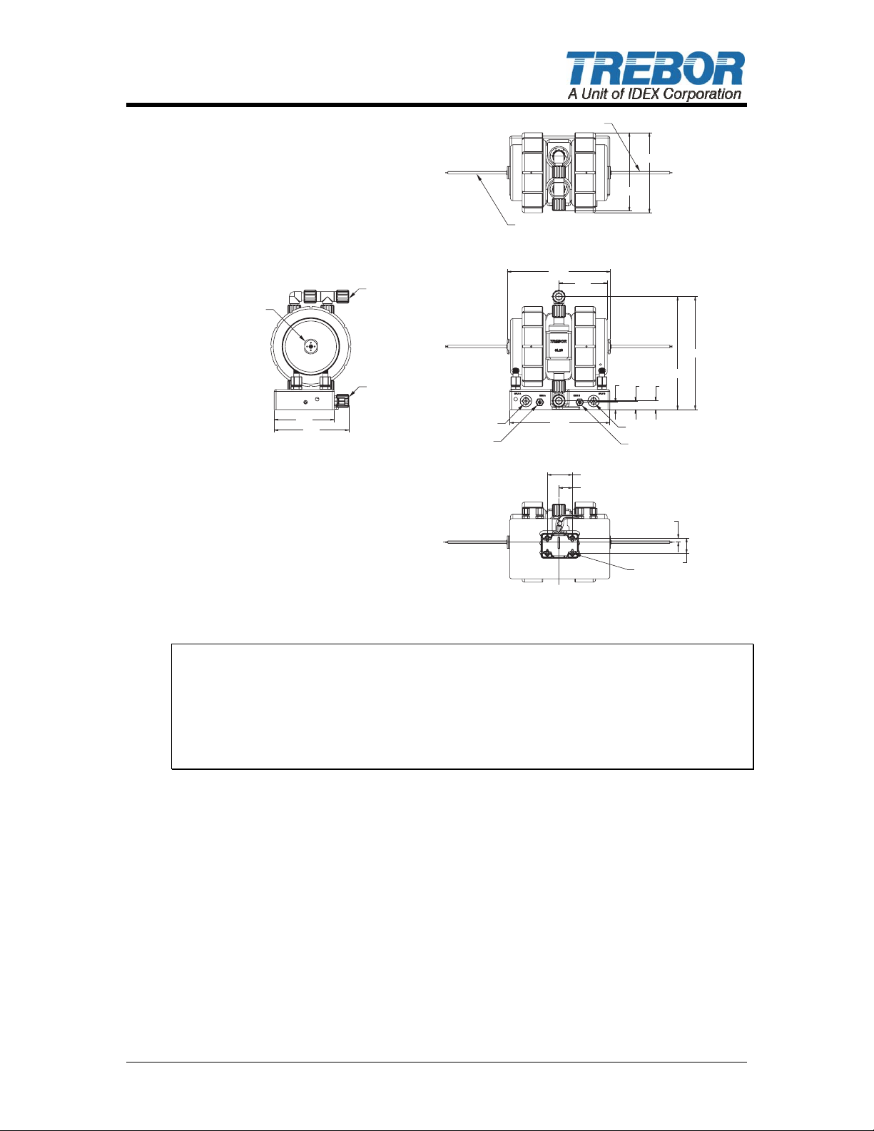
2.2 UTILITIES / HOOK-UP FOR CHAMPION SL20 PUMP
It is recommended that the pump be installed no more than 15° from level to
maintain its self-priming ability and pumping efficiency. This pump mounts on a
quick release base for easy installation. We recommend 1/4 - 20 x 3/4” flat head
counter sink screws.
Air Inlet: 2 each 1/4” OD (6mm) Tube (Pump Air Supply).
2 each 5/16” OD (8mm) Tube (Vacuum Generator Supply).
Fluid Ports: 2 each 3/4” OD Flare Tube Port.
Exhaust: Muffler Standard w/2 each 1/2” NPTF (optional) upon removal of
muffler media.
Sensor: 2 each DP-C-12 EOS probes and seals
PAGE 4 CHAMPION SL20 PUMP OPERATION / MAINTENANCE MANUAL
Page 5
END-OF-STROKE
PROBES
8.00
7.80
END-OF-STROKEEND-OF-STROKE
PROBES
10.29
10.00
4.83
2.50
1.25
.73
11.28
.85
.87
PUMP SUPPLY LINESPUMP SUPPLY LINES
1/4" TUBE FITTING1/4" TUBE FITTING
VACUUM SUPPLY LINESVACUUM SUPPLY LINES
5/16" TUBE FITTING5/16" TUBE FITTING
11.28
END-OF-STROKE
PROBE PORTPROBE PORT
6.00
7.46
OUTLET FLUID PORTOUTLET FLUID PORT
(STD 3/4" FLARE)(STD 3/4" FLARE)
INLET FLUID PORTINLET FLUID PORT
(STD 3/4" FLARE)(STD 3/4" FLARE)
VACUUM SUPPLY LINESVACUUM SUPPLY LINES
5/16" TUBE FITTING5/16" TUBE FITTING
PUMP SUPPLY LINESPUMP SUPPLY LINES
1/4" TUBE FITTING1/4" TUBE FITTING
4x %%c4x %%c.28
Figure 2-11
ATTENTION: Although extensive efforts are made to deliver pumps to our
customers completely dry, new pumps may contain residual moisture from their
final DI water test. It is also recommended that a filter be placed on the
discharge side of the pump.
The pump should be operated with clean, dry air or nitrogen. Particulate, water
and oils in the air supply can damage the pump.
2.3 UTILITIES / HOOK-UP FOR REMOTE CONTROLLER
The Champion SL20 pump will work with many types of external control devices.
Trebor’s electronic Pump Control Module, the PC20, is recommended for its
proven, reliable performance. Please consult factory for assistance with other
external control devices.
2.3.a Trebor’s PC20 Electronic Oscillator
.39
1.50
MTD0381
The PC20 Series external pump controller requires two separately regulated air
supplies; one to drive the vacuum generator, which fills the pump fluid chambers,
and one that controls pump discharge pressure.
In most booster pump applications the vacuum generators are not required and
may be turned off. (See sect, 2.1)
CHAMPION SL20 PUMP OPERATION / MAINTENANCE MANUAL PAGE 5
Page 6

Air Inlet: 1/4” Diameter (6mm) supply tube – 20-80 psig (.14 – .55 MPa)
pump supply.
3/8” Diameter (9mm) supply tube – 80 psig (.42 – .55 MPa)
vacuum supply.
Air Supply: 20-80 psig (.14 – .55 MPa) clean dry air or nitrogen (see
Performance Charts, Section 3.2 for air consumption).
Exhaust: Internal Muffler (1/2” Diameter [13mm] tube optional for remote
exhaust after removing muffler on SL20).
Electronics: +24VDC @ 500ma
TB1: +24VDC
TB2: +0VDC
Sensor: Connect each end-of-stroke probe optic pair to one of the two
optic amplifiers.
Figure 2-22
NOTE: To minimize pump pressure surge use separate air regulators to feed the
pump and ejector supplies.
PAGE 6 CHAMPION SL20 PUMP OPERATION / MAINTENANCE MANUAL
Page 7
3 START-UP
• Pump discharge air supply pressure should be regulated between 20 psig
(.14 MPa) minimum and 80-psig (.55 MPa) maximum.
• Pump Vacuum Air Supply should be regulated at 80 psig (.55 MPa). (Note:
Not required for booster pump installations.)
• Open the fluid suction (IN) line valve, if necessary.
• Open the fluid discharge (OUT) line valve, if necessary.
• Start with pump air supply regulator at low (≈ 20 psi) pressure setting.
• Tune Optics per Section 3.1.i
• Table 33: Consumption / Efficiency in Section 3.2 can be used to determine
approximate air consumption. Air consumption in booster pump applications
will be much less, see Section 3.3.
• Refer to Troubleshooting, Section 5, if pump fails to start.
NOTE: When operating pump as a booster pump, vacuum air supply may be
turned off, conserving air.
CAUTION: When handling potentially dangerous fluids under pressure,
the pump and its fittings should be placed in an enclosure. NOTE: When
operating pump as a booster pump, vacuum air supply may be turned off,
conserving air.
CHAMPION SL20 PUMP OPERATION / MAINTENANCE MANUAL PAGE 7
Page 8
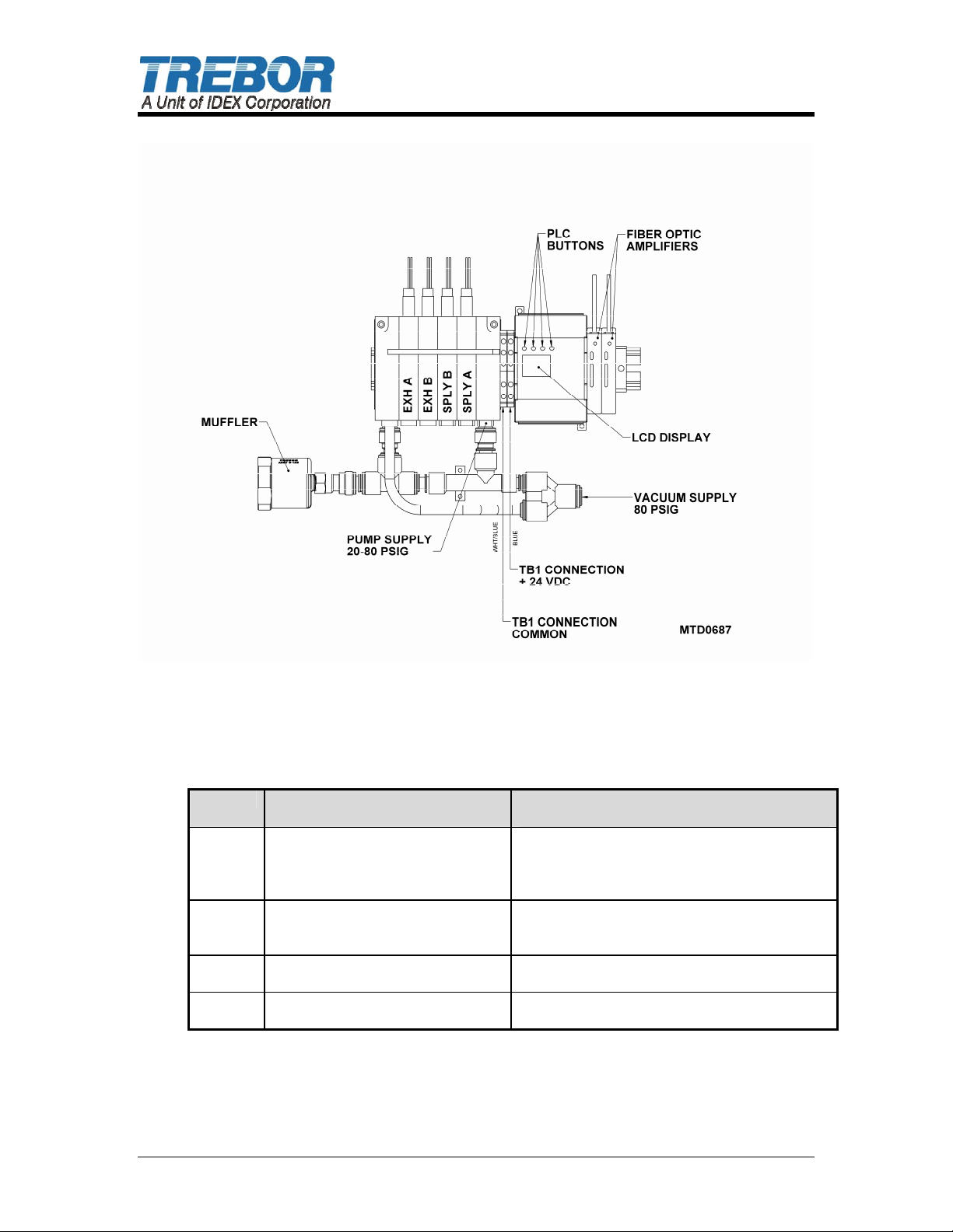
Figure 3-11
3.1 CONTROLLER OPERATION
The controller is operated using the display and buttons on the PLC. See Table
11 for a description of the PLC button functions.
Button Normal mode Numeric value change mode
3
V
U
⇔
Enables numeric value change
mode. (hold for ~3 sec)
Activates desired device change
(hold for ~3 sec)
Scroll backward through devices
to select the desired device
Scroll forward through devices to
select the desired device
Selects a device type (left side of
display) “DM” “RLY”
Table 11: PLC Buttons
(while digit is flashing)
- Activates desired change when pressed
and held for >3 seconds.
- Cancels change when pressed and held
for < 3 seconds
- Decreases value of flashing digit.
-Toggles the “current device value” (“off” to
“on” or from “on” to “off.”)
Increases value of flashing digit
Allows selection of digit to be changed
PAGE 8 CHAMPION SL20 PUMP OPERATION / MAINTENANCE MANUAL
Page 9
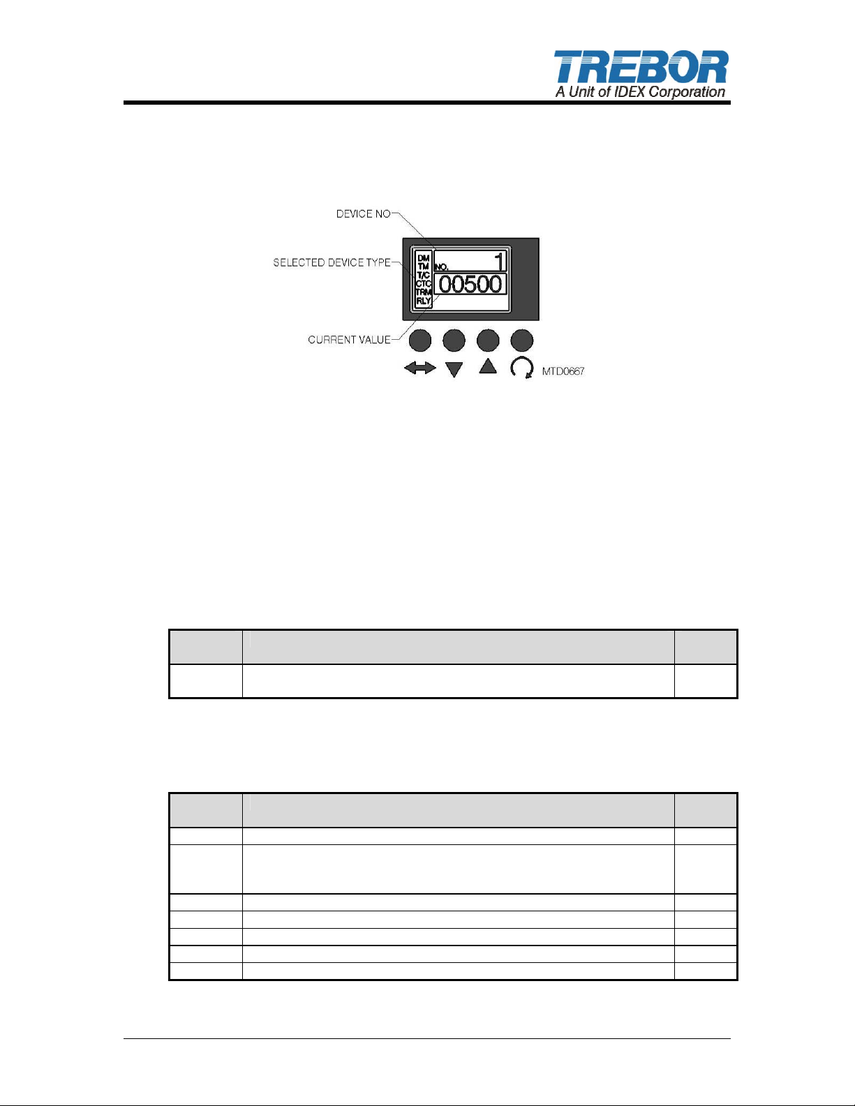
The PLC display is show in Figure 3-22. Please note the names of the different
areas of the PLC display.
Figure 3-22:
3.1.a The PLC outputs are shown in Table 2.
• Relay output 500 is a “fail safe”, normally open relay. It is equipped with
a 15 second delay, intended to identify pump operation.
• Relay 500 will disengage, (turn “OFF”) if the PLC does not recognize
alternating condition of the EOS inputs within the 15 seconds.
• The pump will require manual engagement by turning relay 17901
“ON” (see section 3.1.b).
• During initial start-up relay 500 will be “ON” or in the closed position (~15
seconds) while verification for EOS probe alternation is performed.
RLY
Output
500 Pump Operating - Normally open output OFF
Description Default
Table 2: Customer PLC Output
3.1.b Changing a pump function listed in Table 3:
Value
RLY Description Default
Value
17901 Pump On – Turns pump on and off On
17902 Auto Tune Mode – Enables the auto tuning feature of the
controller
Non manual setup requiring EOS probes.
17903 Reset Auto Tune – Forces the controller to run an auto tune cycle Off
17904 Booster Mode – Enables booster mode disabling vacuum fill. Off
17905 Reset PM – Resets the pump maintenance cycle count Off
17906 N/A Off
17907 Reset to defaults – resets all data memories to default values Off
On
Table 3: PLC Internal Relays
CHAMPION SL20 PUMP OPERATION / MAINTENANCE MANUAL PAGE 9
Page 10

• Push the ⇔ button repeatedly until “RLY” is displayed in the “selected device
type” area of the PLC display.
• Use the V/U buttons to select the desired relay (0-20000). The current relay
number is displayed in the “device no” area of the PLC display.
• Press and hold the 3 button until the “current value” area of the PLC display
begins to flash (~3 seconds).
• Use the V button to toggle the “current value” setting from “off” to “on” or
from “on” to “off.”
• Press and hold the 3 button until the “current value” area of the PLC display
stops flashing (~3 seconds).
Function has now been updated.
3.1.c Turning Pump On and Off
The PLC is shipped with a grounding jumper on input 9. This jumper provides
control of the way the pump is turned on and off.
With the jumper in place the pump is turned on by setting the PLC internal relay
17901 to “ON.” To turn the pump off toggle the PLC internal relay 17901 to
“OFF” per Table 2.
With jumper removed, the pump is turned on by setting relay 17901 to “ON” and
then sinking input 9 of the PLC to 0 volts through an external switch. The pump
is turned off by opening the connection to input 9 of the PLC.
3.1.d Auto Tune Mode
In Auto Tune mode the PLC automatically adjusts the fill time, stroke time, and
seat time of the pump to best match the current operating conditions using EOS
probes.
Auto Tune mode is enabled by setting PLC internal relay 17902 to “ON”.
During auto tuning the controller will first slow the pump’s cycle rate then speed
up the cycle rate of the pump until the optimum cycle rate is achieved. When
operating conditions for the pump change, the PLC will auto detect and run the
auto tune cycle to adjust the pump. The PLC output 1 indicator is turned on
when the PLC is actually running the auto tune program. Blinking indicates Auto
Tune is in progress.
Slow blink indicates pump is being slowed down and fast blink indicates pump
cycle rate is being increased.
3.1.e Manual Tune Mode (Auto Tune-OFF)
Manual mode can be used if the controller is unable to perform a successful auto
tune, or to prevent unwanted auto tuning in applications with varying flow or
pressure demand.
Manual Mode parameters for fill, stroke, and seat time are automatically
transferred over from Auto Tuning when relay 17902 is set to “OFF”. To
manually set parameters see section 3.1.g.
Note: In the case of power loss during Manual mode it is necessary to start up in
Auto tune mode then change to Manual mode.
PAGE 10 CHAMPION SL20 PUMP OPERATION / MAINTENANCE MANUAL
Page 11
3.1.f Booster Mode
In booster mode the controller disables the vacuum generators. Booster mode
can be used in both auto and manual tune modes to take in a low pressure
source and increase the pressure to the desired outlet pressure.
Booster mode is enabled by setting the PLC internal relay 17904 to “on.”
This feature is useful when the pump has a positive fluid inlet pressure greater
than 5 psig to reduce air consumption improving pump efficiency.
3.1.g Preventative Maintenance (PM) Counter
The PLC has a preventative maintenance counter that counts cycles since the
last maintenance was done on the pump. In addition, the pump has a user
adjustable limit for the PM count. When the limit has been reached the display of
the PLC will display the message “User 1.” Pressing any button on the PLC will
clear this message.
The PM counter occupies two registers. The lower register counts to 10,000
then increments the upper register. Thus the PM counter’s value can be
calculated by multiplying the upper register by 10,000 and then adding the lower
register.
The PM counter limit also occupies two registers. The PM limit registers are set
up the same way as the PM counter registers.
For example, to set the PM counter limit to 10,000,000 the PM limit high register
would be set to 1000 and the PM limit lower register would be set to 0.
To reset the PM counter after doing maintenance on the pump, set the PLC
internal relay 17905 to “on” thus toggling the relay. It will immediately return to
“OFF” after resetting the PM counter.
3.1.h Changing PLC data stores listed in table 3:
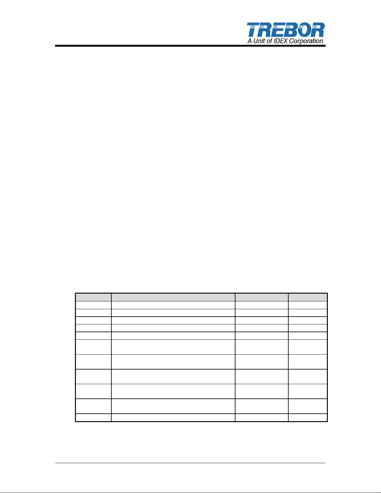
DM Description Range Actions
0 Cycle Rate – in cycles per minute 5 – 70 Read Only
1 Overlap – in milliseconds (400 Default) 0 – 500 Read/Write
2 Fill Time – in milliseconds (500 Default) 50 – 5000 Read/Write
3 Stroke Time – milliseconds (900 Default) 500 – 6000 Read/Write
4 Seat Time – in milliseconds NA – calculated Read Only
5 Fill Error - difference between fill time of
each head as percentage
6 PM Counter High – high order digits of PM
count
7 PM Counter Low – low order digits of PM
count
8 PM Limit High – high order digits of PM
count limit
9 PM Limit Low – low order digits of PM
count limit
10 Auto Tune Delay – in seconds 0 – 60 Read/Write
0 – 100 Read Only
0 – 65535 Read Only
0 – 10000 Read Only
0 – 65535 Read/Write
0 – 10000 Read/Write
Table 22: PLC Data Memories
• Push the ⇔ button repeatedly until “DM” (data memories) is displayed in the
“selected device type” area of the PLC display.
CHAMPION SL20 PUMP OPERATION / MAINTENANCE MANUAL PAGE 11
Page 12
• Use the V/U buttons to select the desired data memory. The current data
memory number is displayed in the “device no.” area of the PLC display.
• Press and hold the 3 button for three seconds until the “current value” area
of the PLC display starts to flash.
• Use the V/U buttons to change the “current value” of the data memory to the
desired value.
• Press and hold the 3 button for three seconds until the “current value” area
of the PLC display stops flashing.
3.1.i Tune Optics
Optic amplifiers are used to monitor the end of stroke probes. To tune these optic
amplifiers you must first set the pump in manual mode per 3.1.e and reset the
DEFAULT values per table 2. Turn pump on per 3.1.c and adjust sensitivity
screws on amplifiers such that the red LED’s increment from 0 to 6 as a
maximum value. CCW reduces the count and CW increases the value.
Inputs 1 & 2 on the PLC will light alternately when set correctly. Upon completion
of optic tuning enable auto tuning per 3.1.d.
3.2 PERFORMANCE CHARTS – PUMPING WITH INLET
SUCTION REQUIRED
Pumping capacity is a function of air supply pressure and volume, suction head,
suction line restrictions, discharge head, discharge line restriction, and fluid
specific gravity and viscosity.
Air Supply
Pressure
(PSIG)
0 0 6.0 16.0
30 0 5.25 16.25
40 0 4.90 17.0
50 0 4.65 17.50
60 0 4.50 18.0
70 0 4.20 18.80
80 0 4.00 19.30
Discharge
Fluid
Pressure
(PSIG)
Discharge
Flow
Maximum
(GPM)*
Air
Consumption
@ 80 psig
(SCFM)
Table 33: Consumption / Efficiency
*0’ Suction
NOTE: Specification to be used to size regulators and control valves.
PAGE 12 CHAMPION SL20 PUMP OPERATION / MAINTENANCE MANUAL
Page 13
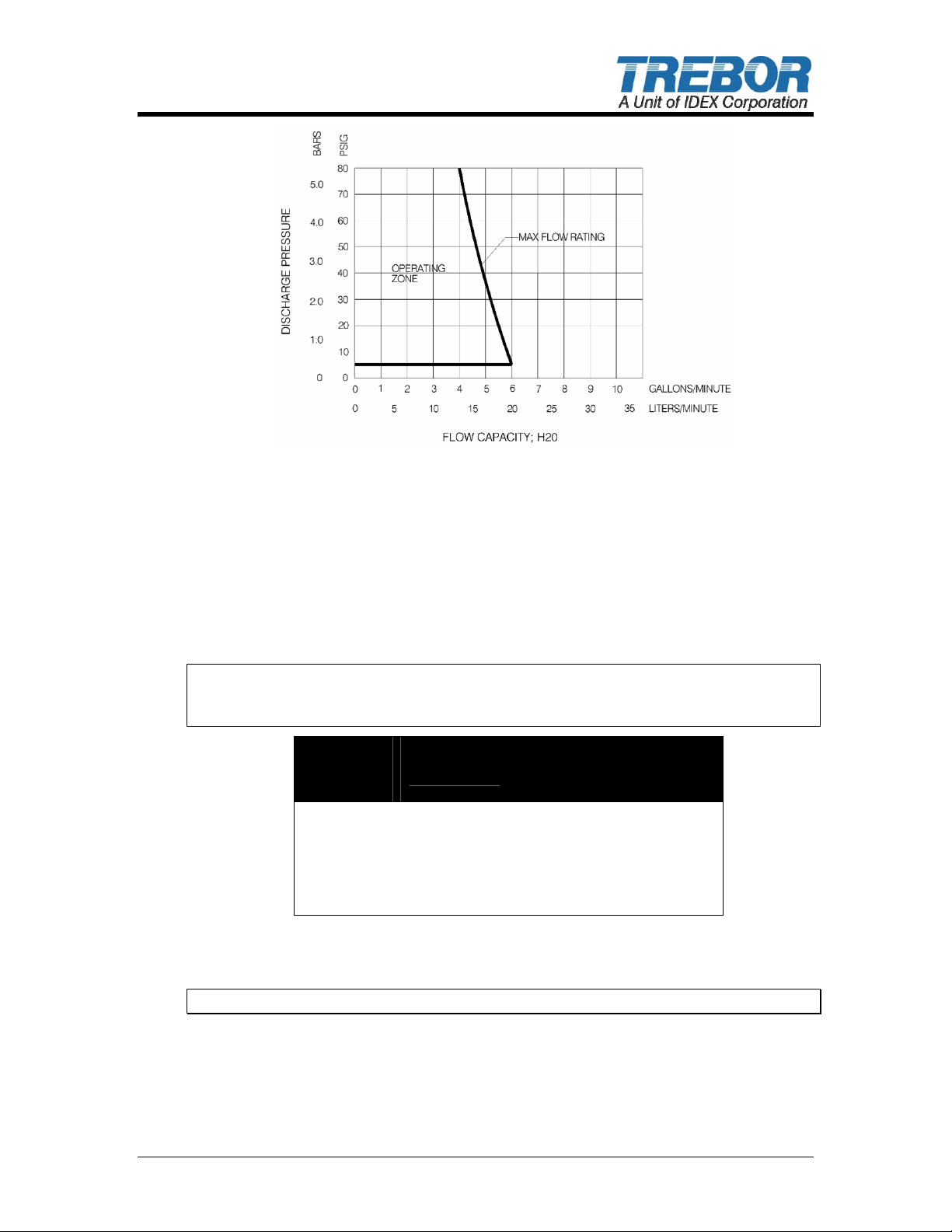
Figure 3-33: Pressure & Capacity Chart
The SL20 can be tuned to operate in virtually any area of the operating zone;
however, pulsation may become more pronounced in flow rates less than 1 GPM
(3.8 LPM) due to the very low stroke rate. Check set up instructions for optimal
tuning.
NOTE: Test information is based on specific conditions using DI water and
limited sampling. Use for general reference only.
3.3 PERFORMANCE CHARTS – BOOSTER PUMPING
Pumping capacity is a function of air supply pressure and volume, suction head,
suction line restrictions, discharge head, discharge line restriction, and fluid
specific gravity and viscosity.
Air Supply
Pressure
(PSIG)
20 0 8.0 2.8
30 0 9.3 4.1
40 0 11.4 5.2
50 0 11.9 6.8
60 0 12.3 8.1
70 0 12.5 8.8
80 0 12.7 9.6
Table 44: Consumption / Efficiency
*@ 15-psi fluid inlet pressure.
NOTE: Specification to be used to size regulators and control valves.
Discharge
Fluid Pressure
(PSIG)
Discharge
Flow
Maximum
(GPM)*
Air
Consumption
@ 80 psig
(SCFM)
CHAMPION SL20 PUMP OPERATION / MAINTENANCE MANUAL PAGE 13
Page 14
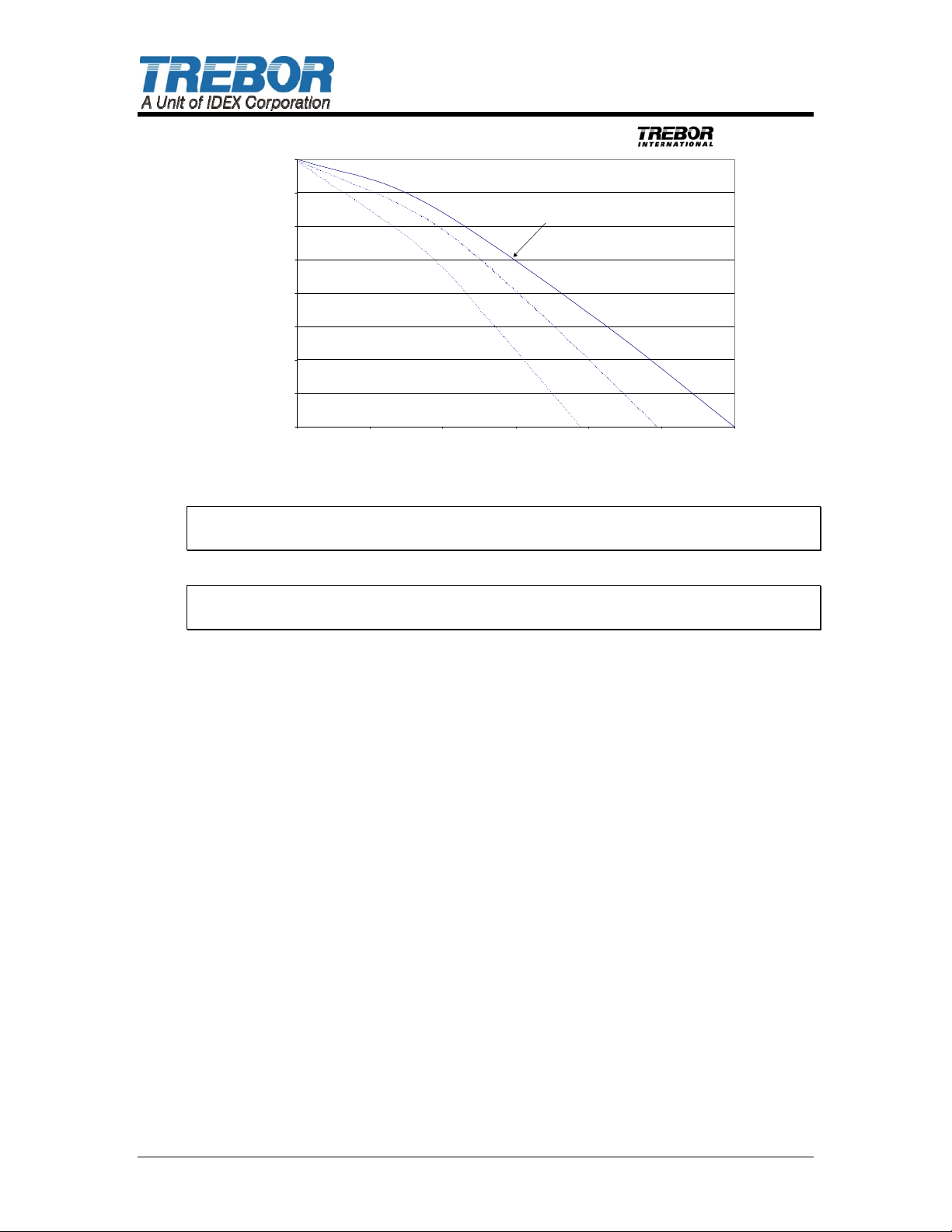
Booster Pump Maximum Performance
80
70
60
50
40
Discharge Pressure (psi)
30
20
10
0
024681012
Performance Curves at 80 ps i Su pply Pressur e
Inlet Pressure
15 psi10 psi5 psi
Outlet Flow (gpm)
Figure 3-44: Pressure & Capacity Chart
NOTE: Test information is based on specific conditions and limited sampling.
Use for general reference only.
NOTE: Maximum flow of pump in booster applications is 12 GPM or 45 LPM @
15 PSIG (.1 MPa) inlet supply.
PAGE 14 CHAMPION SL20 PUMP OPERATION / MAINTENANCE MANUAL
Page 15

4 MAINTENANCE
Trebor pump maintenance can be divided into two categories: air system
maintenance and fluid system maintenance. The purpose of air system
maintenance is to prevent air system failures such as stalling or erratic cycling.
The purpose of fluid system maintenance is to maintain suction and lift
capabilities, and avoid unintended diaphragm failures.
Pump Rebuild Service
Trebor provides a factory repair service for customers using Trebor products.
Please contact Trebor’s Sales Department for current rebuild pricing. The fixed
repair price includes the replacement of all parts in our recommended repair kit.
Each factory rebuild comes with a new one-year warranty. Repairs requiring
more extensive part replacements will be quoted prior to proceeding with the
pump rebuild. If the pump has exceeded its useful life and cannot be rebuilt, the
customer may elect to purchase a new Trebor pump. If the customer chooses
not to rebuild or replace the pump, a $150.00 evaluation charge will be assessed.
All returned pumps are to be shipped freight prepaid with a valid Purchase Order
for the cost of rebuild service. Please contact Trebor’s customer service prior to
returning your pump to obtain an RMA Number and Pump Return Data Sheet to
ensure proper safety precautions. Each pump will be evaluated and repaired
within 5 working days of the receipt of pump at Trebor facility.
4.1 PREVENTIVE MAINTENANCE SCHEDULE
The following maintenance schedule is recommended to optimize pump
performance and minimize failures. Certain operating conditions that require
more frequent maintenance intervals have been noted. In positive pressure inlet
conditions where suction or lift is not required, fluid system maintenance may be
extended.
Adhering to the recommended preventative maintenance schedule along with
periodic inspection of the pump will ensure continued efficient operation and
overall reliable pump performance. Your actual experience in a specific
application may allow modification to this schedule.
It is recommended that the Preventive Maintenance Record (Section 4.1.a) be
copied, maintained and kept with this unit for future reference.
CHAMPION SL20 PUMP OPERATION / MAINTENANCE MANUAL PAGE 15
Page 16
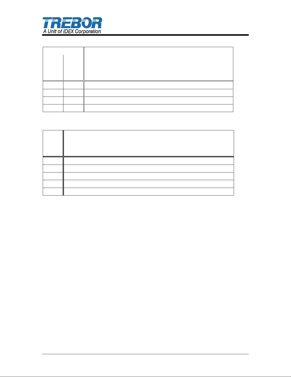
Champion SL20 (Slurry Applications)
Service
Component / Comments
Semi-
Annual
X Replace Muffler Media in Base (see 22, Section 4.4)
X X Replace Check Balls and O-Rings (see 4 & 5, Section 4.4)
X Replace Diaphragms (see 9, Section 4.4)
X X Replace Check Port Seals (see 6, Section 4.4)
Annual
Champion SL20 (Non-Slurry Applications)
Bi-
Annual
X Replace Muffler Media in Base (see 22, Section 4.4)
X Replace Check Balls and O-Rings (see 4 & 5, Section 4.4)
X Replace Diaphragms (see 9, Section 4.4)
X Replace Check Port Seals (see 6, Section 4.4)
X Replace Quick Exhaust Seals (see 31, Section 4.4)
Component / Comments
PAGE 16 CHAMPION SL20 PUMP OPERATION / MAINTENANCE MANUAL
Page 17

4.1.a Preventive Maintenance Record
Company Name: _____________________________________________________
Company Address: _____________________________________________________
_____________________________________________________
Product: _________________ Serial Number: ________________
Date: ________ Tech: _____ Notes: ________________________________________
________________________________________
Date: ________ Tech: _____ Notes: ________________________________________
________________________________________
Date: ________ Tech: _____ Notes: ________________________________________
________________________________________
Date: ________ Tech: _____ Notes: ________________________________________
________________________________________
Date: ________ Tech: _____ Notes: ________________________________________
________________________________________
Date: ________ Tech: _____ Notes: ________________________________________
________________________________________
Date: ________ Tech: _____ Notes: ________________________________________
________________________________________
Date: ________ Tech: _____ Notes: ________________________________________
________________________________________
Date: ________ Tech: _____ Notes: ________________________________________
________________________________________
Date: ________ Tech: _____ Notes: ________________________________________
________________________________________
Date: ________ Tech: _____ Notes: ________________________________________
________________________________________
Date: ________ Tech: _____ Notes: ________________________________________
________________________________________
Date: ________ Tech: _____ Notes: ________________________________________
________________________________________
Date: ________ Tech: _____ Notes: ________________________________________
________________________________________
Date: ________ Tech: _____ Notes: ________________________________________
________________________________________
Date: ________ Tech: _____ Notes: ________________________________________
________________________________________
Date: ________ Tech: _____ Notes: ________________________________________
________________________________________
Date: ________ Tech: _____ Notes: ________________________________________
________________________________________
Date: ________ Tech: _____ Notes: ________________________________________
________________________________________
Date: ________ Tech: _____ Notes: ________________________________________
________________________________________
Date: ________ Tech: _____ Notes: ________________________________________
________________________________________
Date: ________ Tech: _____ Notes: ________________________________________
________________________________________
Date: ________ Tech: _____ Notes: ________________________________________
________________________________________
Date: ________ Tech: _____ Notes: ________________________________________
________________________________________
CHAMPION SL20 PUMP OPERATION / MAINTENANCE MANUAL PAGE 17
Page 18

4.2 RECOMMENDED SPARE PARTS
KRSL20U-00-B Spares Rebuild Kit, which includes:
Part No
KMSL20U-00-B 1
KDSL20-00-B 1
1700C0047 4 Diaphragm, M50
W0151 2 Fiber Optic Target
98003047 2 Seal, Quick Exhaust
AS026 4 Muffler Pad
In critical applications, a spare pump is recommended to minimize possible down
time during service intervals.
Qty Description
4.3 TOOLS
The following tool kit is recommended as standard service equipment.
KTSL20-00-B Tool Kit, which includes:
Part No
98003108 1 Torque Wrench, 30-150 ft/lb., 1/2” Drive
98003150 1 Tool Case
98003305 1 Drive Handle
98003306 1 15/16” Wrench
T0129 1 Strap Wrench
T0145 1 Check Assembly Tool
T0148 1 1/2” Pin Tool
T0149 1 ¾” Optic Cap Pin Tool
T0153 1 Rebuild Fixture
Qty Description
Maintenance Kit
Includes: (4)
(4)
(4)
Diaphragm Kit
Includes: (4)
(2)
98001415
98002334
AS006
1700C0047
W0151
Check Ball, PTFE
O-Ring, PTFE, -312
Seal, PTFE, 1.5x.82
Diaphragms
Fiber Optic Target
PAGE 18 CHAMPION SL20 PUMP OPERATION / MAINTENANCE MANUAL
Page 19
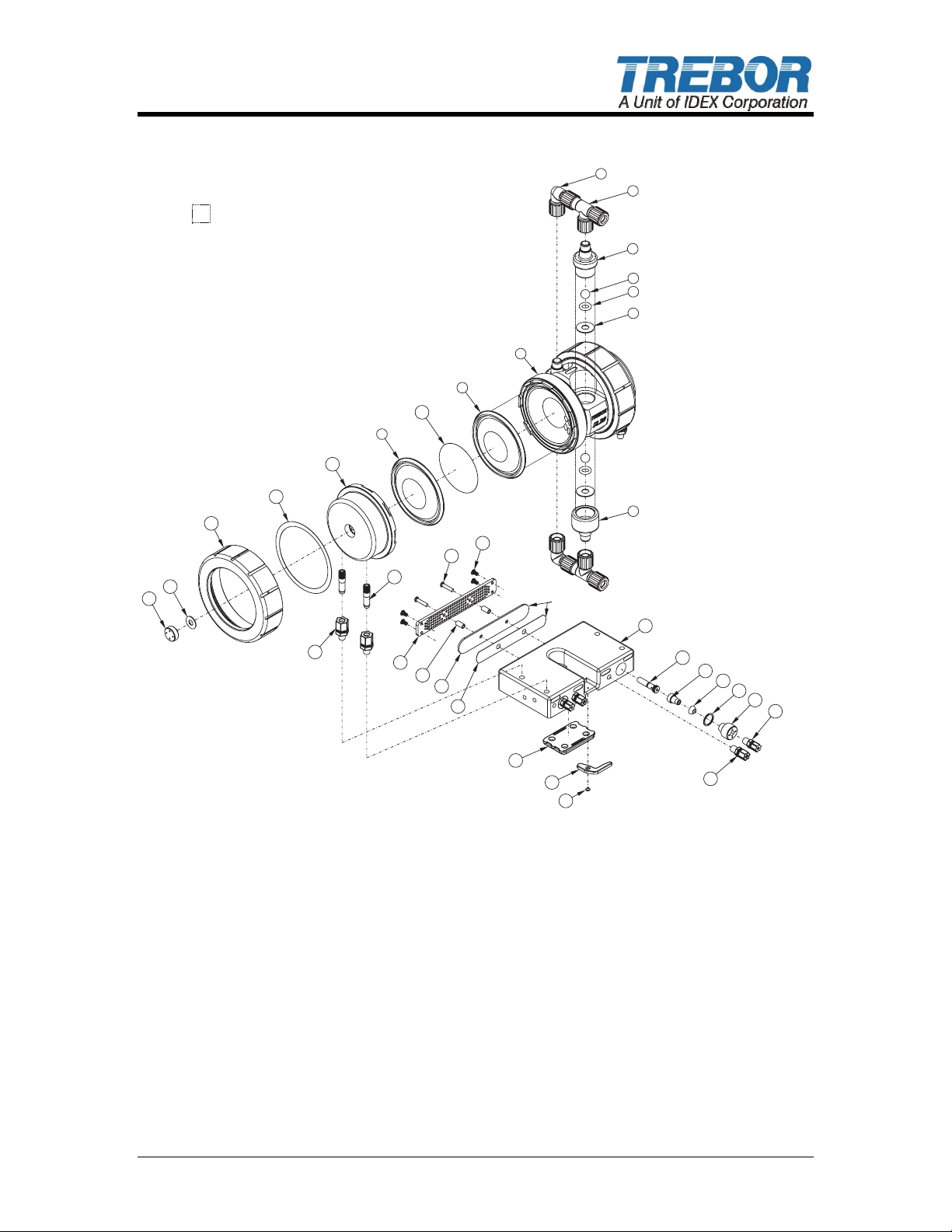
4.4 PARTS ILLUSTRATION
1
2
BORDERS REPRESENTBORDERS REPRESENT
FLUID CONTACT AREASFLUID CONTACT AREAS
3
4
5
6
8
9
10
9
11
12
13
19
18
14
15
16
17
LAYER ALTERNATELYLAYER ALTERNATELY
ITEM 22 (4X) & ITEM 23 (3X)ITEM 22 (4X) & ITEM 23 (3X)
20
21
22
23
24
25
26
7
34
33
32
31
30
29
28
27
MTD0220
CHAMPION SL20 PUMP OPERATION / MAINTENANCE MANUAL PAGE 19
Page 20
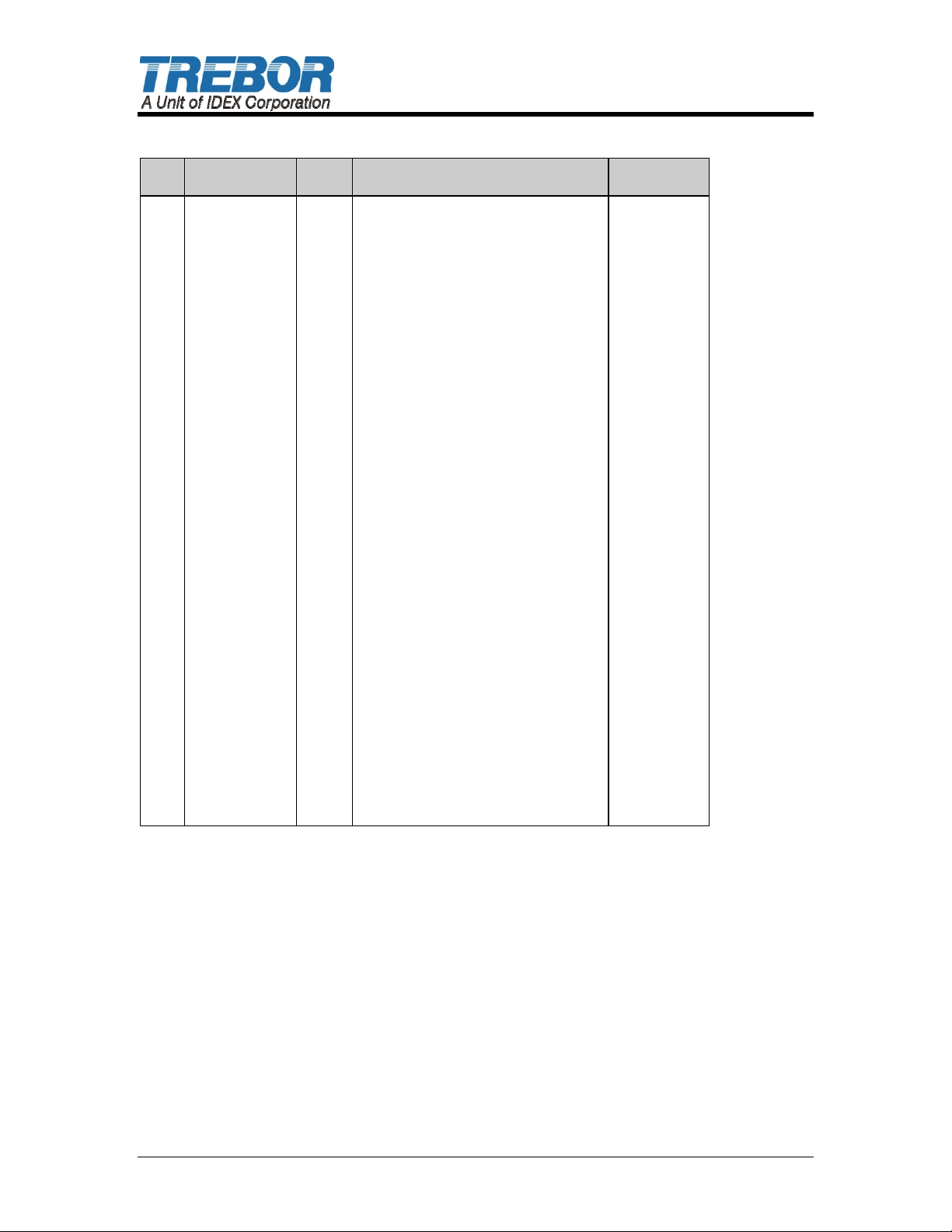
4.5 PARTS LIST
ILL
PART NO QTY DESCRIPTION MATERIAL
NO
1 98002891 2 Fitting, Flare, EL, 3/4RFTx3/4RF PFA
2 98002904 2 Fitting, Flare, Tee,
3/4T x 3/4RF x 3/4T
3 AS004 2 Check, Discharge, SL20 PTFE
4 98001415 4 Check Ball, 3/4” Diameter PTFE
5 98002334 4 O-Ring, -312 PTFE
6 AS006 4 Seal, 1.5 x .62 x .06 PTFE
7 AS005 2 Check, Suction, SL20 PTFE
8 AS003 1 Body, Pump, SL20 PTFE
9 1700C0047 4 Diaphragm, Maxim 50 PTFE
10 W0151 2 Target, 2.5 Diameter PTFE
11 AS007 2 Head, Remote, SL20 PP
12 AK097 2 Washer, Slip, M50 PTFE
13 AK003 2 Nut, Union, Maxim 50 PP
14 AK030 2 Seal, Pilot Cap, Maxim PTFE
15 AM009 2 Cap, Pilot, Maxim 25 PP
16 98003260 4 Fitting, MC, Black, 1/2T x 1/4P PP
17 AK182 4 Transfer Tube PFA
18 98003314 2 Screw, 1/4-20 x 1.25 PP
19 98003235 4 Screw, 1/4-20 x .50 PP
20 AS023 1 Panel, Muffler, Baffled PP
21 98003315 2 Spacer, 3/8 x 1/4 x 3/4L PP
22 AS026 4 Pad, Muffler, SL20 PP
23 AS027 3 Baffle, Muffler, SL20 PE
24 AK088 1 Base, Mounting, Molded, M50 PP
25 AK108 1 Lever, Large, Molded PP
26 98003071 1 SCR, Nat, 10-32 x .250 PP
27 98003286 2 Fitting, MC, White, 5/16T x 1/4P PP
28 AS032 2 Fitting, Restrictor PP
29 AS012 2 Cap, QE, CMP, Remote PP
30 W0116 2 Seal, Pilot Cap PTFE
31 98003047 2 Seal, QE VITON
32 AS011 2 Adapter, QE UHMW
33 98003285 2 Insert, Vacuum Generator PEEK
34 AS024 1 Base, CMP, Remote PP
NS DP-C-12 2 End-of-Stroke Probe
Replace item 15.
NS W0154 2 Seal, Probe (included in DP-C-12)
Replace item 14.
PFA
PP / PTFE
PTFE
PAGE 20 CHAMPION SL20 PUMP OPERATION / MAINTENANCE MANUAL
Page 21
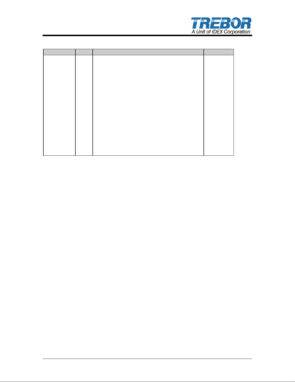
4.6 CONTROLLER PARTS LIST – PC20
PART NO QTY DESCRIPTION
98001151 .33 ft. Tube, Polye, 3/8’OD, .06W
98001153 12 ft. Tube, HDPE, Natural, 1/4 Diameter
98001590 13 ft. Wire,18G,Wht/Blu
98001620 14 ft. Wire,18G,Lt Blu
98002088 1 ft. Rail, Din 3, 35 x 7.5 x 1
98002504 1 End, Terminal Stop, Pin
98002871 3 Block, Terminal, Multi
98002872 1 End,Terminal,Multiclamp,Din
98002672 2 Sensor,Fiberoptic, 24VDC,NPN
98003287 1 Fitting, VAC, Gen, Hiflow, 5/1
98003288 1 Fitting, ACTL, 5/16T x 5/16T x 3/8
98003289 2 Fitting, ACTL, 5/16T x 3/8T, Red
98003703 1 Fitting, ACTL, PC, 3/8Tx1/4P, FC
98003290 1 Fitting, ACTL, 3/8T, Tee, PC
98003292 13.5 ft Tube, HDPE, Natural, 5/16 Diameter
98003293 12 ft. Tube, HDPE, Black, 5/16 Diameter
98003294 12 ft. Tube, HDPE, Black, 1/4 Diameter
98003503 1 Controller,PLC,16 I/O,24VDC
AS014 1 Assembly, Valve, 4 POS, VQ2000
BB024 1 Assembly, Muffler, Non-ADJ
4.7 CLEAN-UP
To help remove potentially dangerous chemicals prior to service or shipment, the
pump should be flushed with DI water or disassembled and thoroughly cleaned.
Allow DI water to flush through the inlet and out the outlet to prevent pressure
build up.
4.8 DISASSEMBLY
During the life of the pump it will be necessary to perform certain preventative
maintenance procedures to ensure its continued high performance. This section
and the next (4.9 Assembly) are provided for the user’s convenience in
disassembly and re-assembly procedures.
• Loosen quick grip nuts on the transfer tubes from the pump base using
13/16” open-end wrench.
• Remove pump assembly from the pump control base.
• Immerse or flush the pump assembly using DI water and a neutralizing agent.
• Remove suction check caps and seal on bottom of pump body using T0145
pin tool.
• Remove ball, O-ring and cap seal.
• Remove discharge check caps and seal on outlet side of pump.
• Remove ball, O-ring, and cap seal.
4.8.a Body Disassembly
• Install mounting fittings in pump discharge check ports on top of the pump.
Turn over and lock body into bench mounting fixture. NOTE: Securely attach
mounting fixture to work surface using hardware provided.
• Remove the transfer tubes from pump heads using 1/4” Allen wrench.
CHAMPION SL20 PUMP OPERATION / MAINTENANCE MANUAL PAGE 21
Page 22
• Using strap wrench, turn union nuts counter-clockwise to remove.
• Remove head and check diaphragms for cracks or cuts.
• To remove diaphragms, slit diaphragm with a sharp knife and pull the
diaphragms from the grooves. (Do not pry on diaphragm seal groove, as
this will damage the sealing surface.)
CAUTION: Following disassembly, parts should be thoroughly washed
and soft scrubbed to be free from chemical residue for handling purposes.
4.8.b Control Base Disassembly
• Unlock control base from quick-change mount by pulling out lever on front of
base to unlock mount. Then slide base back until it stops. Lift base off
mount.
• Using pH test strips evaluate whether base has any contamination in air
passages, especially the muffler area. If present, neutralize using best
methods prior to disassembly.
• Remove 1/4” screws and remove muffler assembly from base. Note position
of 2 each 1/4-20 x 1” screws.
• Remove white 1/4” tube fitting from quick exhaust cap.
• Using pin tool #T0103, remove quick exhaust caps and quick exhaust seals.
4.8.c Cleaning
• Gently spray clean or dunk rinse all components with DI water to remove any
trace materials remaining after disassembly. Gently scrub areas requiring
material removal. Avoid main V seal region to prevent damage to walls.
4.9 ASSEMBLY
Prior to beginning assembly, inspect all parts to ensure they are clean and dry.
Wear clean protective gloves. Precautions should be exercised to prevent
contaminating any of the air chamber surfaces with chemicals during handling.
4.9.a Control Base Assembly
ATTENTION: Threads should be snug. Do not over tighten.
• Install muffler assembly into base and reinstall (6) 1/4 - 20 retaining screws.
• Install new quick exhaust seals in port, pointing out and resting on the quick
exhaust adapter.
• Reinstall Seals and quick exhaust caps to hand tight using tool #T0103.
• Reinstall 1/4” air fitting in quick exhaust cap.
• Remount pump base on Quick Change Mount and reconnect airlines.
4.9.b Pump Assembly
• Reattach pump to assembly fixture.
PAGE 22 CHAMPION SL20 PUMP OPERATION / MAINTENANCE MANUAL
Page 23

• Attach union nut to one side of pump body (hand tight). Do not install
diaphragm on this step. This will protect body during initial pump assembly.
• Remove pump from the assembly fixture.
• Place pump body with union nut down and place two diaphragms, removing
all air from between diaphragms, with “V” groove point toward the body. Be
sure to install Fiber Optic Target between diaphragms.
• Install head on body. Note tab alignment and orientation of transfer tube
ports in head.
• Install slip ring and union nut on pump while gently pressing down on the
head to engage tabs in head and body, spin union nut down hand tight.
• Turn pump over and remove union nut to install diaphragms and target as
before.
• Repeat diaphragm, head, slip ring and union installation.
• Lock body into mounting fixture.
• Using strap wrench, torque union nuts slowly to 75 ft-lbs. with the wrench at
90° +/- 15° to the nut’s surface as shown.
• Remove pump from assembly fixture.
• Install check cap seal, O-ring and ball in suction ports.
• Install suction caps 1/8 turn past hand tight.
• Install check cap seal, O-ring and call in discharge ports.
• Install discharge caps 1/8 turn past hand tight.
4.9.c Final Assembly
• Reinstall transfer tubes in head ports using 1/4” Allen wrench. Ensure
transfer tubes are tight.
• Position pump control base on mounting plate, slide base forward, use
locking lever to secure.
• Loosely attach quick grip nuts to transfer tube ports on control base.
• Install pump onto control base by inserting transfer tubes in pump into quick
grip nuts on control base.
• To secure pump to control base, tighten quick grip nuts one (1) full turn past
hand tight using 13/16” wrench.
• Reconnect both air supply and fluid lines.
CHAMPION SL20 PUMP OPERATION / MAINTENANCE MANUAL PAGE 23
Page 24

5 TROUBLESHOOTING
Pump Will Not Start, Fails to Operate
Cause: Solution:
Insufficient air pressure.
•
End of Stroke Probes not tuned
•
Insufficient air volume (low supply
•
pressure during running).
Fluid discharge line blocked.
•
Downstream valve closed, filter plugged
or other obstruction.
Supply lines cross.
•
Surging.
•
Bubbles in Fluid Discharge
Cause: Solution:
Leaking fluid inlet fitting.
•
Leaking main seal.
•
Pump inlet line pressure reached
•
saturation point (due to high suction
requirement).
Ruptured (perforated) diaphragm.
•
Must be minimum 20 psig at 1/4” pump air hook-up and 80
•
psig at 3/8” hook-up.
See Section 3.1.i
•
See Performance Charts (3.2) for requirements. Check
•
for both regulator and control valve capabilities.
Remove obstruction.
•
Pump supply lines are color and size coded for easy hook-
•
up. One color per pump sides.
Reset controller speed to higher CPM. Increase CPM to
•
minimize surging. Activate auto tune.
Turn on Auto Tune feature.
Replace inlet manifold.
•
Tighten union nut to 75 ft-lbs. or replace diaphragms, and
•
check head and body seal grooves for nicks or scratches.
Increase diameter of suction supply line (reduces
•
restriction).
Reduce output flow.
Replace diaphragms.
•
Fluid Leaks
Cause: Solution:
Leaking main seal.
•
Check bore cap.
•
Ruptured diaphragm(s) can result in
•
fluid leaks through air exhaust port.
Tighten union nuts to 75 ft-lbs.
•
Replace diaphragms.
Check head and body seal grooves for nicks or scratches.
Tighten, or remove and replace seal.
•
Replace diaphragms, and any parts that may have been
•
damaged by fluid exposure.
Erratic Cycling
Cause: Solution:
Solenoid valve failure.
•
Suction line restricted (cavitation).
•
End of Stroke Probes not tuned
•
Check ball(s) not seating.
•
Quick exhaust seal failure
•
Inspect and replace solenoid valve assembly.
•
Reduce fluid restriction.
•
See Section 3.1.i
•
Check O-rings for damage; replace if necessary.
•
Make sure check balls move freely in sleeves.
Replace quick exhaust seal.
•
PAGE 24 CHAMPION SL20 PUMP OPERATION / MAINTENANCE MANUAL
Page 25
6 WARRANTY
CHAMPION SL20 PUMP
Trebor International, Inc. warrants to the purchaser of new equipment
manufactured by Trebor to be free from defects in material and workmanship
when used for its intended purpose under normal operating conditions, and
maintained according to the Operation/Maintenance Manual.
Trebor’s obligation under this warranty is limited to repairing or replacing, at
Trebor’s option and at the Trebor factory, any part or parts thereof which shall,
within 1 year after delivery thereof to the original purchaser, be demonstrated to
Trebor’s satisfaction to have been defective. This does not include normal wear
and tear on consumable parts such as check valve components and diaphragms.
Damage caused by ingesting foreign objects shall not be covered by this
warranty.
This warranty may be transferred to subsequent owners. The warranty period is
based on the original ship date from the factory. All warranty related freight costs
shall be borne by the customer.
This warranty shall not apply to any equipment which, in the judgment of Trebor,
shall have been repaired or altered outside Trebor’s factory in any way, so as to
affect its performance or reliability; subjected to misuse, negligence or accident;
or used other than in accordance with Trebor’s printed instructions.
There are no terms, conditions or warranties, expressed, implied or
statutory, of merchantability, fitness, capacity, or otherwise, of the goods
ordered, other than, or different from, the warranty set forth above. This
warranty takes precedence over any other warranty, expressed or implied.
Trebor neither assumes, nor authorizes any other party to assume for it, any
liability in connection with said equipment except as set forth above.
CHAMPION SL20 PUMP OPERATION / MAINTENANCE MANUAL PAGE 25
 Loading...