

Page 1

Phone: 800-669-1303 or 801-561-0303
Fax: 801-255-2312
e-mail: [email protected]
SS95
Surge Suppressor
Operation / Maintenance
Manual
SERIAL NUMBER (located on top of product):
PATENTS: U.S. 05971402 10/28/05 – MSS95-C
Page 2

CONTENTS
1 INSTALLATION............................................................................................................3
1.1 UNPACKING ......................................................................................................3
1.2 LOCATING / MOUNTING SURGE.....................................................................3
1.2.a Port Mounted.........................................................................................4
1.2.b Inline, Internal Ports...............................................................................4
1.2.c Inline, External Ports .............................................................................6
2 MAINTENANCE ...........................................................................................................7
2.1 PREVENTIVE MAINTENANCE SCHEDULE.....................................................7
2.2 RECOMMENDED SPARE PARTS ....................................................................7
2.3 TOOLS................................................................................................................7
2.4 PARTS ILLUSTRATION.....................................................................................8
2.5 PARTS LIST.......................................................................................................9
2.6 CLEAN-UP..........................................................................................................9
2.7 DISASSEMBLY ..................................................................................................9
2.8 CLEANING .......................................................................................................10
2.9 ASSEMBLY ......................................................................................................10
2.9.a Head Assembly ...................................................................................10
2.9.b Final Assembly ....................................................................................10
3 WARRANTY...............................................................................................................11
SS95 SURGE OPERATION / MAINTENANCE MANUAL CONTENTS
Page 3

1 INSTALLATION
1.1 UNPACKING
After unpacking, the Surge Suppressor should be checked for any damage that
may have occurred during shipment. Damage should be reported to the carrier
immediately.
The following items should be included within the shipping container:
Qty Item Description
1 SS95 SS95 Surge Suppressor
1 MSS95 Operation/Maintenance Manual
1 ** Seal, Port
**Dependent upon type of pump option selected.
1.2 LOCATING / MOUNTING SURGE
• Remove port plug from pump.
• Install new port seal.
• Hand tighten surge suppressor into port. Do not over tighten.
ATTENTION: Over-tightening adapter into pump will result in pump damage.
• Run 1/8 bleed line to drain. In the event of a diaphragm failure fluid may flow
through tube to drain.
• Connect air supply using 3/8” or larger air line. Air supply to Surge
Suppressor must be equal to or greater than pump supply pressure.
NOTE: When connecting the SS95 to an externally controlled pump, do not
connect the SS95 air supply via a tee from the pump. Connect to a separate
continuous supply.
SS95 SURGE OPERATION / MAINTENANCE MANUAL PAGE 3
Page 4
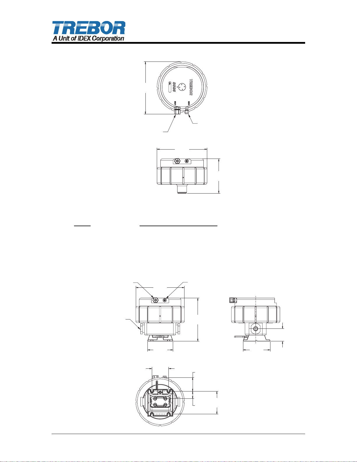
1.2.a Port Mounted
8.30
(21.08)
AIR SUPPLYAIR SUPPLY
CONNECTION
3/8" TUBE3/8"
TUBE
8.00
(20.32)
REMOTE EXHAUSTREMOTE EXHAUST
CONNECTION
1/8" TUBE1/8"
TUBE
Figure 1-1
Pump Assembled Height: IN (CM)
MEGA 960 15.06 (38.25)
MAXIM 25 12.22 (31.04)
MAXIM 50 13.97 (35.48)
1.2.b Inline, Internal Ports
AIR SUPPLYAIR SUPPLY
CONNECTION
3/8" TUBE3/8"
TUBE
8.00
(20.32)
REMOTE EXHAUSTREMOTE EXHAUST
CONNECTION
1/8" TUBE1/8"
TUBE
5.47
(13.89)
IN
(CM)
MTD0375
CL
FLUID PORTFLUID PORT
FITTINGS (INCLUDEDFITTINGS
WITH TEE OPTION)WITH
(INCLUDED
TEE OPTION)
4.20
(10.67)
2.75
(6.99)
7.11
(18.06)
2.28
(5.79)
1.21
(3.07)
3.75
(9.53)
4.47
(11.35)
2.06
(5.23)
IN
(CM)
MTD0376
PAGE 4 SS95 SURGE OPERATION / MAINTENANCE MANUAL
Page 5
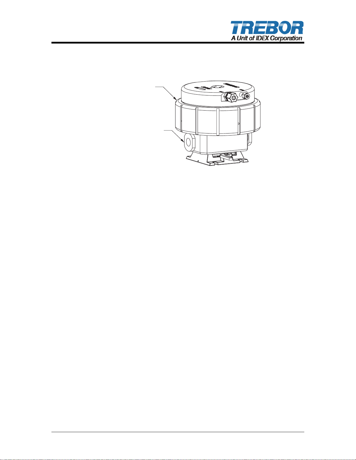
Figure 1-2
Assembled Height: IN (CM)
7.11 (18.06)
95 SURGE95 SURGE
SUPPRESSOR
TEE ASSEMBLYTEE ASSEMBLY
(INCLUDES FLUID(INCLUDES
PORT FITTINGS & BASE)PORT
FLUID
FITTINGS & BASE)
Available Options
Inline,1” Flare
Inline,3/4” Flare
Inline,3/4” Stubout
Figure 1-3
MTD0373
SS95 SURGE OPERATION / MAINTENANCE MANUAL PAGE 5
Page 6
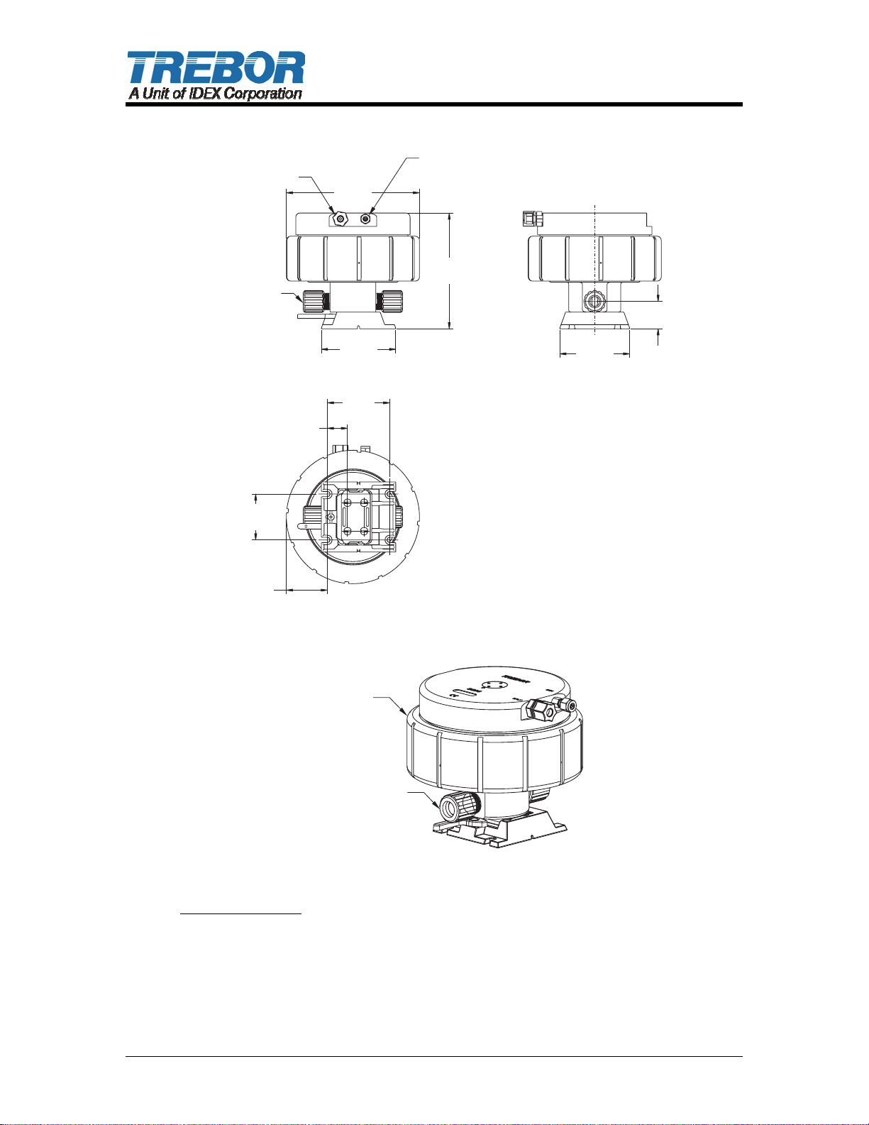
1.2.c Inline, External Ports
AIR SUPPLYAIR SUPPLY
CONNECTION
3/8" TUBE3/8"
TUBE
3/4" FLARE3/4" FLARE
2.75
(6.99)
1.21
(3.07)
8.00
(20.32)
4.47
(11.35)
3.75
(9.53)
REMOTE EXHAUSTREMOTE EXHAUST
CONNECTION
1/8" TUBE1/8"
TUBE
6.94
(17.63)
CL
1.64
(4.17)
4.20
(10.67)
2.46
(6.25)
Available Options
Inline, 3/4” Flare
SS95
3/4" FLARE, INLINE3/4" FLARE, INLINE
(INCLUDES BASE)(INCLUDES
BASE)
Figure 1-4
Figure 1-5
MTD0542
IN
(CM)
MTD0543
PAGE 6 SS95 SURGE OPERATION / MAINTENANCE MANUAL
Page 7
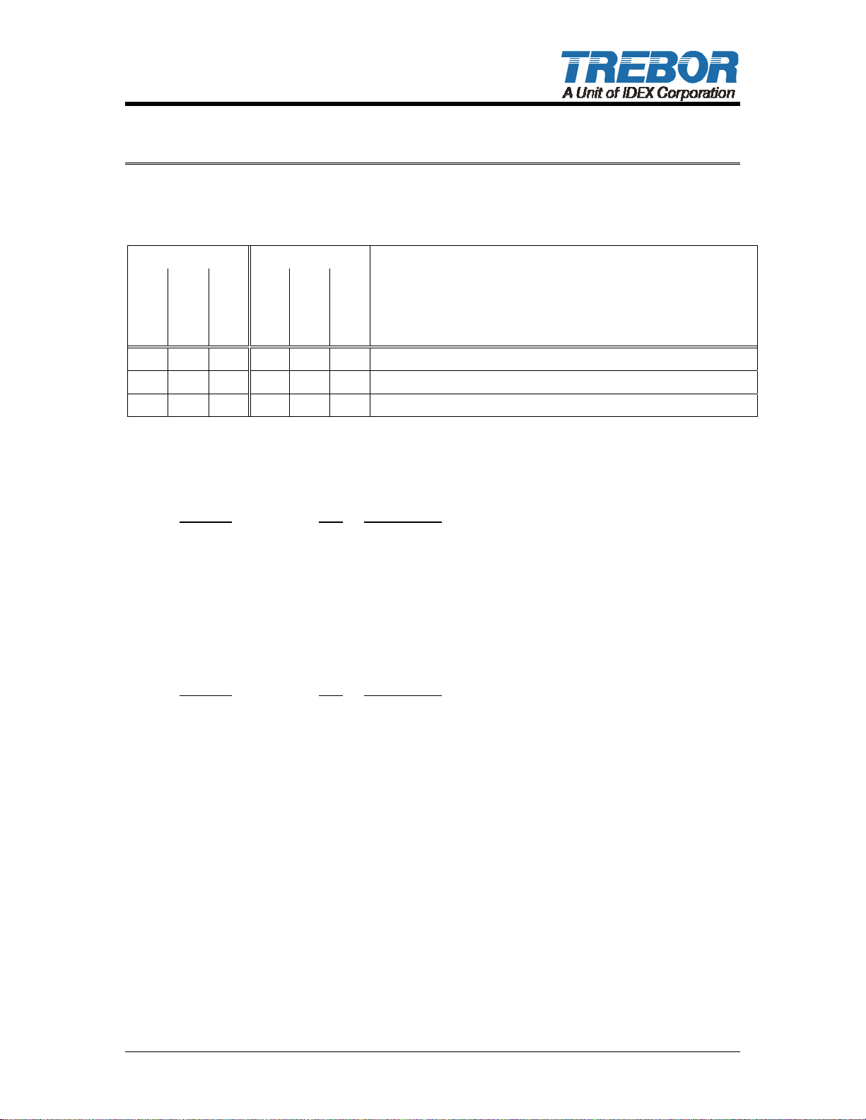
2 MAINTENANCE
2.1 PREVENTIVE MAINTENANCE SCHEDULE SS95 Surge Suppressor
Replacement Inspection
Component /
1 Year
2 Year
4 Year
X Poppet Pilot Valves and Seats
X X Diaphragms
X Union Nut Retorque
2.2 RECOMMENDED SPARE PARTS
KRSS95-00-A Spares Rebuild Kit, which includes:
1 Year
6 Month
2 Year
Comments
Part No Qty Description
1700C0047 1 Diaphragm
98002450 1 O-ring
AK020 1 Pilot Poppet
AK030 1 Pilot Seal
AL023 1 Pilot Seat
2.3 TOOLS
Include:
Part No Qty Description
98003108 1 Torque Wrench, 30-150 Ft. Lb.
98003305 1 1/4” Drive Handle
T0129 1 Strap Wrench
T0146 1 3/4” Pin Tool
1 Bench Vise
SS95 SURGE OPERATION / MAINTENANCE MANUAL PAGE 7
Page 8
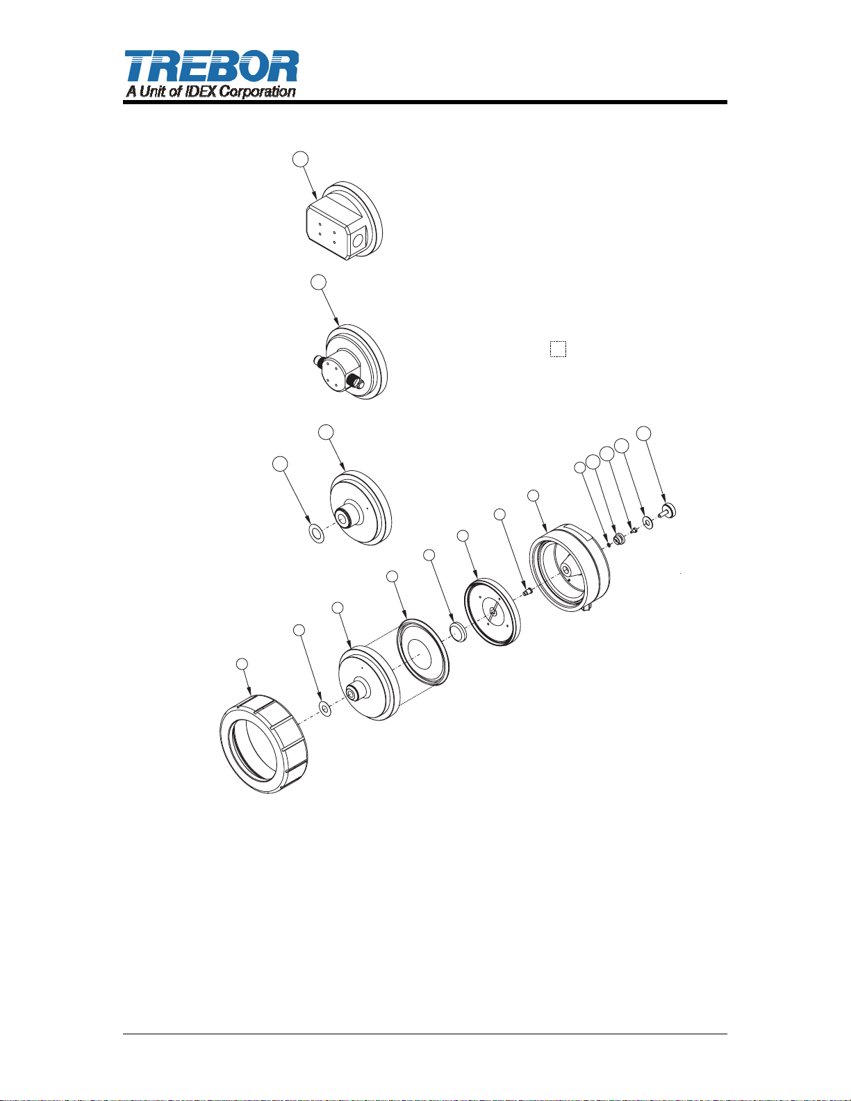
2.4 PARTS ILLUSTRATION
3C
3B
BORDERS REPRESENTBORDERS REPRESENT
FLUID CONTACT AREAFLUID
CONTACT AREA
3A
2A
8
7
6
5
4
3
2
1
10
9
11
13
12
MTD0561
PAGE 8 SS95 SURGE OPERATION / MAINTENANCE MANUAL
Page 9
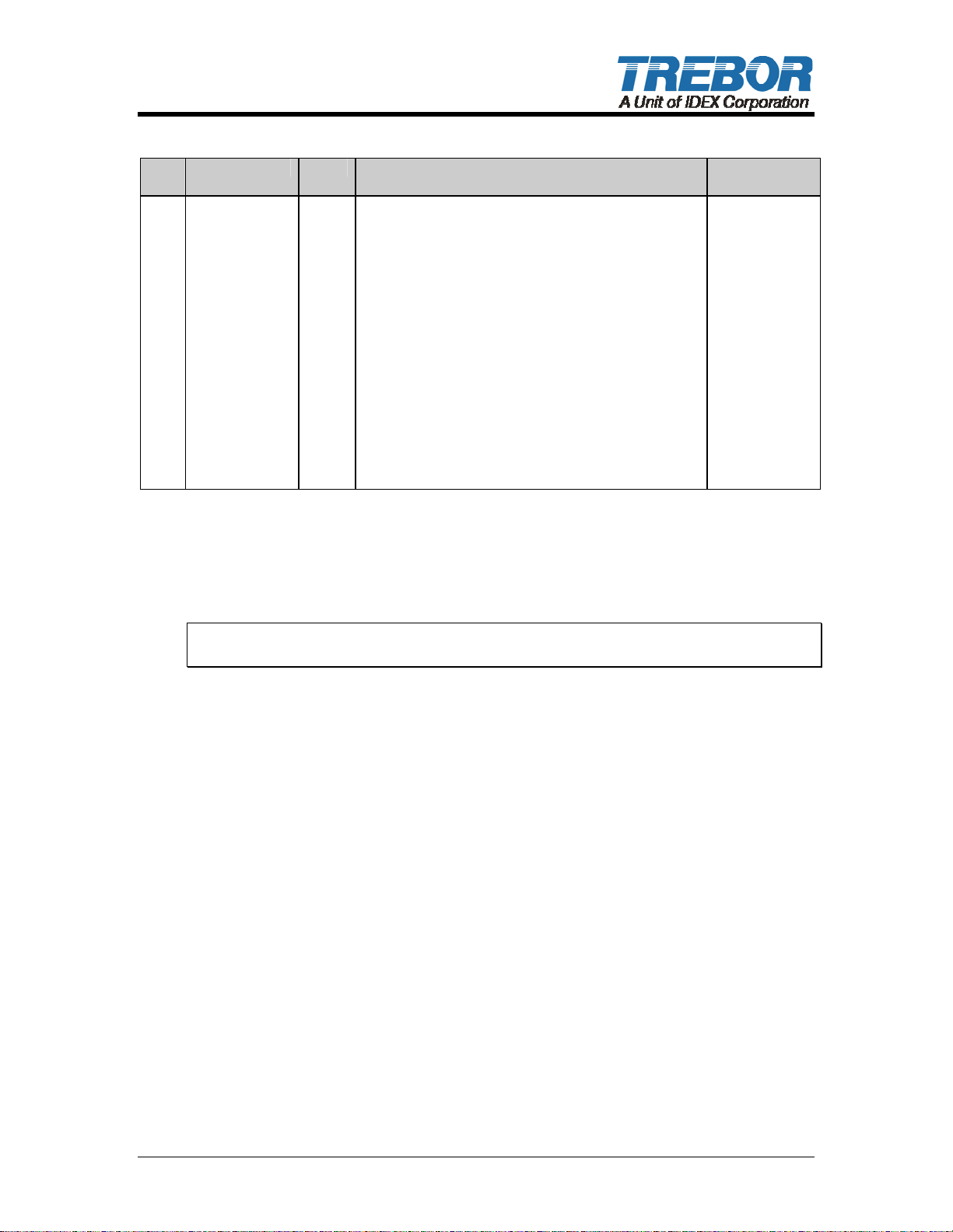
2.5 PARTS LIST
ILL
NO
1 AL003-01 1 Union Nut PVDF
2 AM084 1 Seal,1.380x.63x.02 PTFE
2a L0163 1 Seal,1.75x1.00x.02 PTFE
3 AL026 1 Body, Maxim to SS95 PTFE
3a AL027 1 Body, 960 to SS95 PTFE
3b AL039 1 Body, Inline Connection. External PTFE
3c AL038 1 Body, Inline Connection, Internal PTFE
4 1700C0047 1 Diaphragm PTFE
5 J0093 1 Push Plate PTFE
6 AL019 1 Support Plate PTFE
7 AL014 1 Shaft PFA
8 AL001 1 Head PP
9 98002450 1 O-Ring FFKM
10 AL023 1 Pilot Seat PTFE
11 AK020 1 Pilot Poppet PFA
12 AK030 1 Pilot Cap Seal PTFE
13 AL004 1 Pilot Cap PP
PART NO QTY DESCRIPTION MATERIALS
(PP optional)
2.6 CLEAN-UP
To help remove potentially dangerous chemicals prior to service or shipment, the
surge Suppressor should be flushed with DI water or disassembled and
thoroughly cleaned. Allow DI water to flush in and out to prevent pressure build
up. Surge Suppressor can also be submerged in a rinse tank for clean up.
NOTE: When handling Surge Suppressor, wear appropriate personal protection
gear, including safety glasses.
2.7 DISASSEMBLY
During the life of the Surge Suppressor it may be necessary to perform certain
preventative maintenance procedures to ensure its continued high performance.
This Section and Section
in disassembling and re-assembling the Surge Suppressor.
• Thoroughly clean/flush the Surge Suppressor using DI water (See Section
2.6 Clean-Up).
• Remove Surge Suppressor, from Pump or fluid line.
• Remove safety tube fitting and air inlet fitting.
• Secure Surge Suppressor in Bench mounted vice across the flats in the
head. To prevent aesthetics damage to head, use a protective barrier
between vice and head.
• Remove union nut using the strap wrench, turning the nut counter clockwise
to loosen.
• Pull the body away from the diaphragms. NOTE: Do not pry on body seal
groove, this will damage the sealing surface.
2.9 Assembly are provided for the user’s convenience
• To remove diaphragms cut a slit in diaphragm with knife and pull the
diaphragms from the support plate. NOTE: Do not pry on Support Plate seal
groove, this will damage the sealing surface.
SS95 SURGE OPERATION / MAINTENANCE MANUAL PAGE 9
Page 10

• Remove support plate from head.
• Remove push plate from shaft.
• Remove head from vice.
• Remove pilot cap and seal from head using 3/4” Pin Tool.
• Remove pilot poppet from head.
• Remove pilot seat from head using 3/4” Pin Tool.
NOTE: Following disassembly, parts should be thoroughly washed and be free
from chemical residue for handling purposes.
2.8 CLEANING
Gently spray clean or tank rinse all components with DI Water to remove any
trace of materials remaining after disassembly.
2.9 ASSEMBLY
Prior to beginning assembly, inspect all parts to ensure they are clean and dry.
Damaged or worn parts should be replaced, along with all air and fluid seals.
Wear clean protective gloves. Precautions should be exercised to prevent
contaminating any of the air chamber surfaces with chemicals during handling.
2.9.a Head Assembly
• Thread pilot seat into head using 3/4” pilot centering end of Pin Tool. Light
hand tight; do not over tighten, damage will occur.
• Install pilot poppet into pilot seat in head.
• Install seal and pilot cap into head tighten using 3/4” Pin Tool.
2.9.b Final Assembly
• Secure Head in bench mounted vice across the flats to prevent aesthetic
damage use a protective barrier between vice and head.
• Install shaft through support plate; thread push plate onto shaft hand tight.
• Install assembled support plate into head.
• Install diaphragms onto support plate.
• Note V-groove orientation of diaphragms.
• Install body onto diaphragms.
• Thread union nut onto head using strap wrench turning clock-wise to tighten.
Torque to 75 ft-lbs.
PAGE 10 SS95 SURGE OPERATION / MAINTENANCE MANUAL
Page 11

3 WARRANTY
SS95 SURGE SUPPRESSOR
TREBOR International, Inc. warrants to the purchaser of new equipment
manufactured by TREBOR to be free from defects in material and workmanship
when used for its intended purpose under normal operating conditions, and
maintained according to the Operation/Maintenance Manual.
TREBOR’s obligation under this warranty is limited to repairing or replacing, at
TREBOR’s option and at the TREBOR factory, any part or parts thereof which
shall, within 2 years after delivery thereof to the original purchaser, be
demonstrated to TREBOR’s satisfaction to have been defective. This warranty
may be transferred to subsequent owners. The warranty period is based on the
original ship date from the factory. All warranty related freight costs shall be
borne by the customer.
Excessive wear to pump components caused by pumping abrasive solutions or
chemicals, as well as damage caused by ingesting foreign objects shall not be
covered by this warranty.
This warranty shall not apply to any equipment which, in the judgment of
TREBOR, shall have been repaired or altered outside TREBOR’s factory in any
way, so as to affect its performance or reliability; subjected to misuse, negligence
or accident; or used other than in accordance with TREBOR’s printed
instructions.
There are no terms, conditions or warranties, expressed, implied or
statutory, of merchantability, fitness, capacity, or otherwise, of the goods
ordered, other than, or different from, the warranty set forth above. This
warranty takes precedence over any other warranty, expressed or implied.
TREBOR neither assumes, nor authorizes any other party to assume for it, any
liability in connection with said equipment except as set forth above.
SS95 SURGE OPERATION / MAINTENANCE MANUAL PAGE 11
 Loading...