

Page 1
Phone: 800-669-1303 or 801-561-0303
Fax: 801-255-2312
e-mail: [email protected]
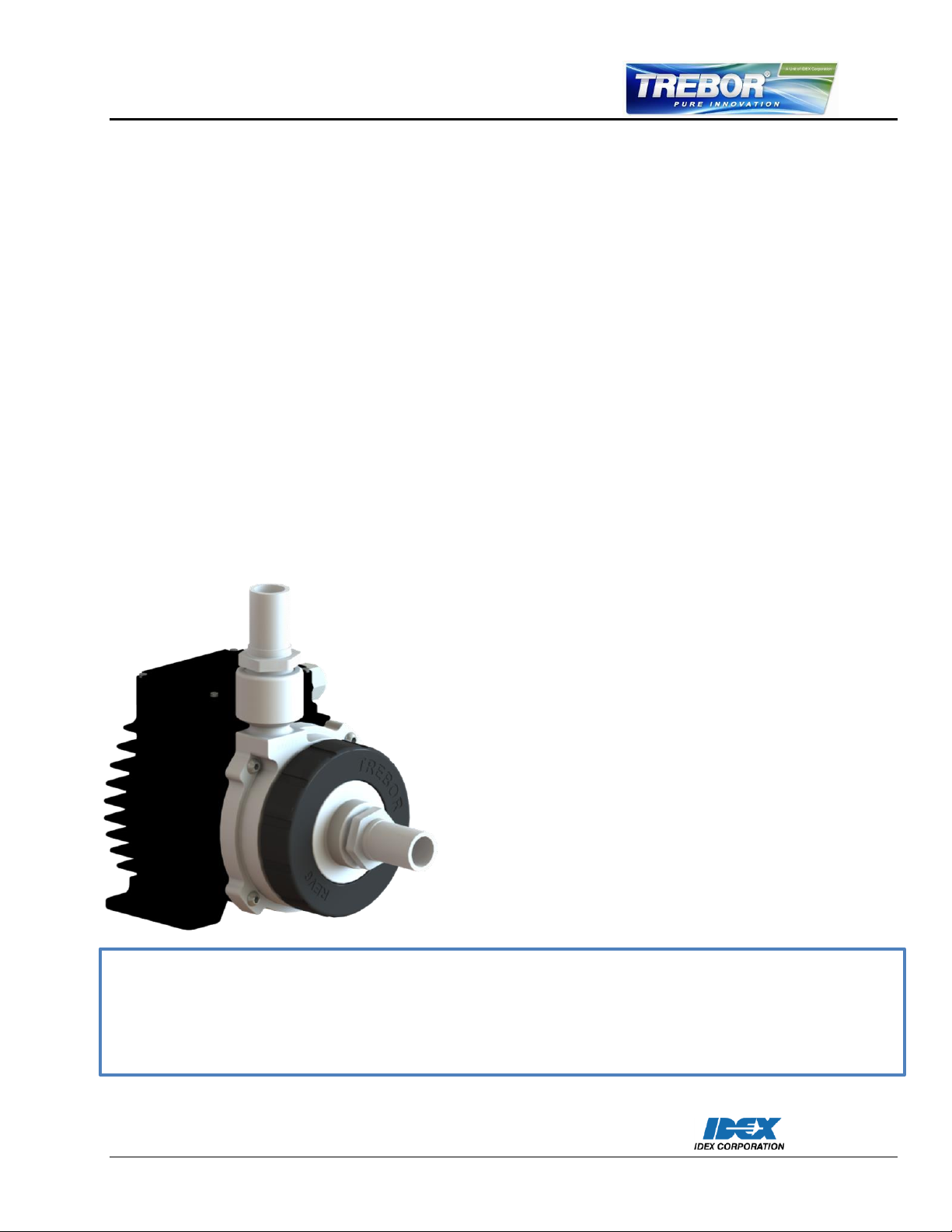
This manual contains information necessary for the safe and proper use of the Rev6. Included are specifications
for the standard configurations of the pump system and instructions regarding its use, installation, operation,
adjustment, inspection, and maintenance. For special configurations of the pump system, refer to accompanying
information. Please familiarize yourself with the contents of the manual to ensure the safe and effective use of
this product. After reading this manual, please store the manual where the personnel responsible for operating
the pump system can readily refer to it at any time.
REV6
Operation / Maintenance
Manual
SERIAL NUMBER (located on the product):
06/20/2014 – REV6-A
Page 2

Table of Contents
1 Safety Precautions ......................................................................................................................... 4
2 Specifications ................................................................................................................................. 5
2.1 Specification of Components ................................................................................................... 5
2.2 Standard System Configurations ............................................................................................. 7
2.2.1 Pump Only Configuration ................................................................................................. 7
2.2.2 Stand-Alone System Configuration ................................................................................... 7
2.3 General Environmental Conditions .......................................................................................... 9
2.4 Pump Performance Curves ..................................................................................................... 9
2.4.1 Pressure-Flow Curves ...................................................................................................... 9
2.4.2 NPSHr Curves .................................................................................................................10
2.4.3 Maximum Static Pressure vs. Fluid Temperature ............................................................10
2.5 Basic Dimensions of Main Components .................................................................................11
2.6 Air Cooling Module .................................................................................................................13
2.7 Cable Minimum Bend Radius .................................................................................................14
3 Engineering Information ................................................................................................................15
3.1 Sealing and Material Concept .................................................................................................15
3.2 Power Consumption ...............................................................................................................16
3.3 Temperature Monitoring .........................................................................................................17
3.4 Thermal Management ............................................................................................................18
3.4.1 Motor Temperature ..........................................................................................................18
3.4.2 Controller Temperature ...................................................................................................20
3.5 Hydraulic Circuit Design .........................................................................................................21
4 Installation.....................................................................................................................................22
4.1 Electrical Installation of Controller ...........................................................................................22
4.1.1 Overview .........................................................................................................................22
4.1.2 General Installation Instructions ......................................................................................23
4.1.3 Electrical Installation of Standalone Operation ................................................................23
4.2 Mechanical Installation of the Pump/Motor .............................................................................25
4.3 Mechanical Installation of the Controller .................................................................................25
4.4 Mechanical Installation of Adapter/Extension Cables..............................................................25
5 Operation ......................................................................................................................................26
5.1 System Operation with Standalone Controller ........................................................................26
5.1.1 State Diagram of Standalone Controller ..........................................................................26
5.1.2 Standalone Operation (Button Control Mode) ..................................................................27
5.1.3 Extended Operation (Analog Control Mode) ....................................................................27
REV6 OPERATION / MAINTENANCE MANUAL CONTENTS
Page 3

5.1.4 Error Display on the Integrated Panel ............................................................................. 28
6 Inspection and Maintenance ......................................................................................................... 29
6.1 Impeller Replacement Interval ............................................................................................... 29
6.2 Impeller Replacement Procedure ........................................................................................... 29
6.2.1 Preparation ..................................................................................................................... 29
6.2.2 Instructions for Replacement .......................................................................................... 30
7 Troubleshooting ............................................................................................................................ 31
7.1 Troubleshooting for Operation with Standalone Controller ..................................................... 31
8 Technical Support ........................................................................................................................ 32
9 Appendix ...................................................................................................................................... 33
9.1 Regulatory Status .................................................................................................................. 33
9.1.1 CE Marking ..................................................................................................................... 33
9.2 Symbols and Signal Words .................................................................................................... 34
REV6 OPERATION / MAINTENANCE MANUAL 3 CONTENTS
Page 4
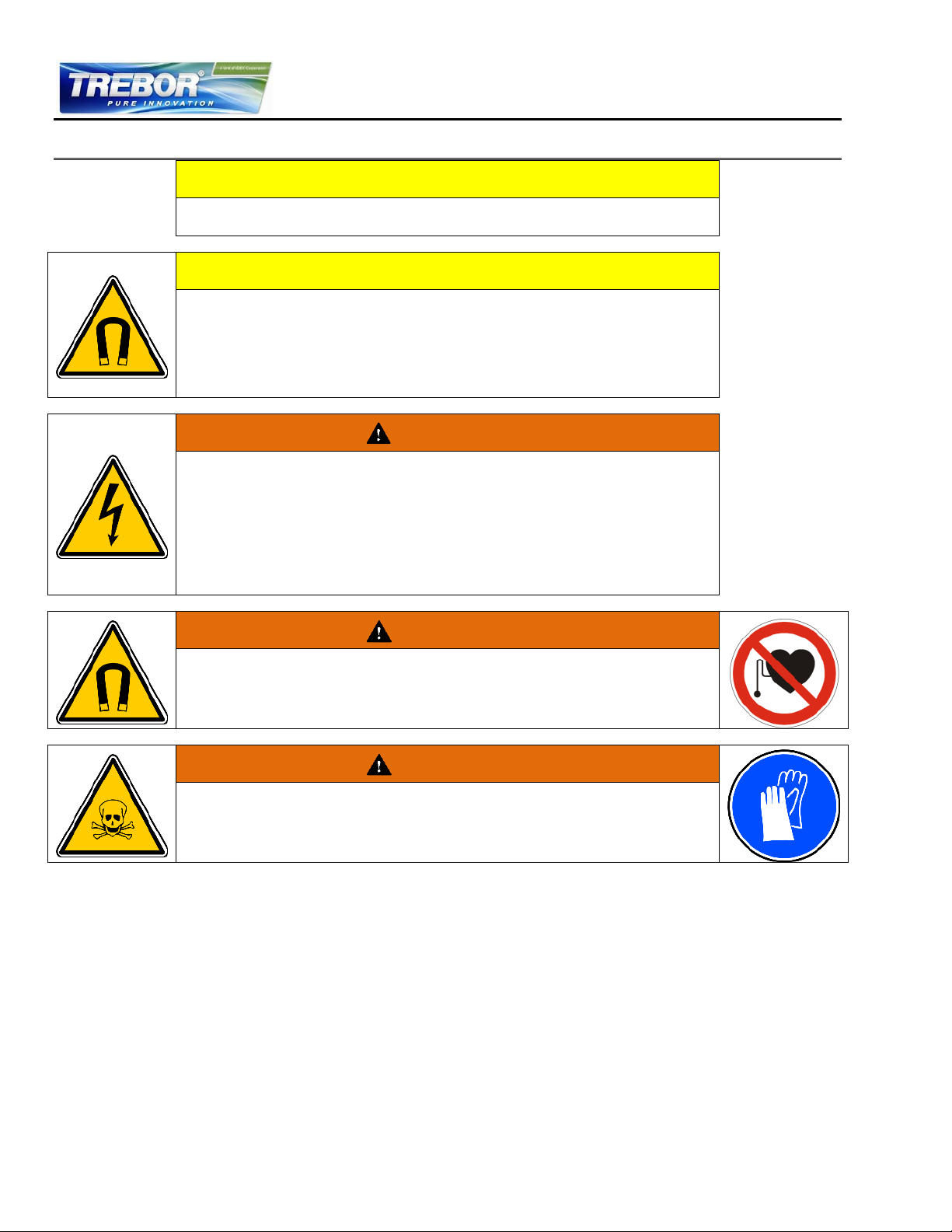
CAUTION
Do not open the motor or controller. Trebor does not assume responsibility
for any damage occurring under such circumstances.
CAUTION
High magnetic field strength of pump impeller
The pump system contains a rotor magnet with high field strength. This may
alter or damage the calibration of sensitive electronic devices and
measuring instruments in the immediate surroundings. Keep at a safe
distance from computers, monitors and all magnetic data storage media
(e.g. disks, credit cards, audio and video tapes etc.)
WARNING
Hazardous voltage may be present.
In case of the usage of an inadequate AC/DC power supply, mains voltages
may be present (even if the system is designed for 48VDC). The usage of a
galvanic separated power supply, which is certified by a 3rd party (UL or CE),
is highly recommended.
The controller must be grounded and placed in a spill protected
environment. Do not under any circumstances open the powered controller.
The usage of galvanic separated AC/DC supply is highly recommended.
WARNING
High magnetic field strength of pump impeller
The pump system contains a rotor magnet with high field strength.
Pacemakers may be influenced and magnetic forces may lead to
contusions. Keep distance to pace makers and handle impeller with care.
WARNING
TOXIC CHEMICALS may be present.
When using the system to pump chemicals skin contact and toxic gases
may be hazardous to your health. Wear safety gloves and other appropriate
safety equipment.
1 SAFETY PRECAUTIONS
REV6 OPERATION / MAINTENANCE MANUAL 4 CONTENTS
Page 5
Component
Item
PN
Description
Materials of Construction
Pump
1
BM001
Pump Casing
PTFE
2
98004267
Pump Impeller
PFA flow path
3
98004268
Pump Main Seal
Semiconductor grade FFKM
4
BM002
Inlet Housing
PTFE TFM 1600
5
BM003
Union Nut
Polypropylene
Fluid Port Adapter
6 Seal
See Table 3 for details
7
Fluid Port
Adapter
Motor Attachment
Bolts
8
98004269
M6x25mm
QTY 4
316 stainless steel
2 SPECIFICATIONS
2.1 Specification of Components
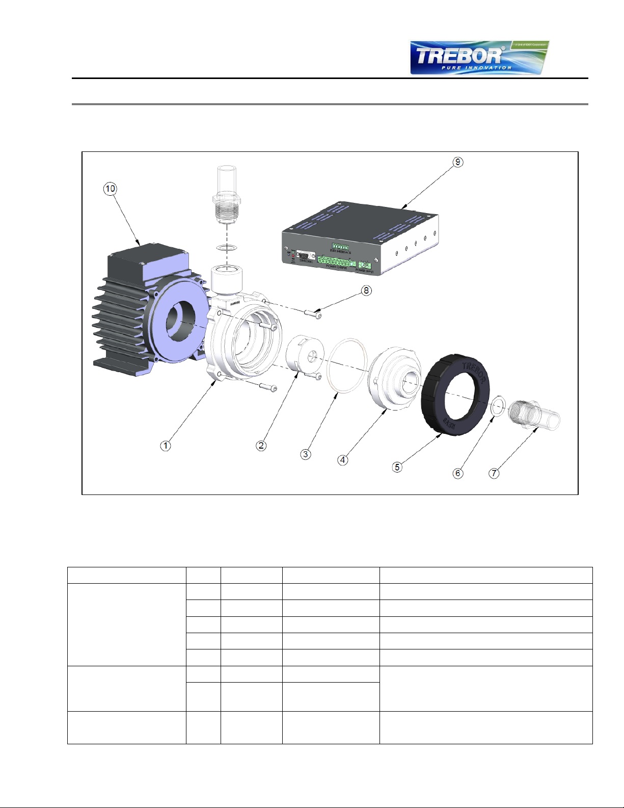
Figure 1 shows the main system components. The accessories are listed below.
Each Rev6 pump system is comprised of a pump, a motor, a controller, and two fluid port adapters.
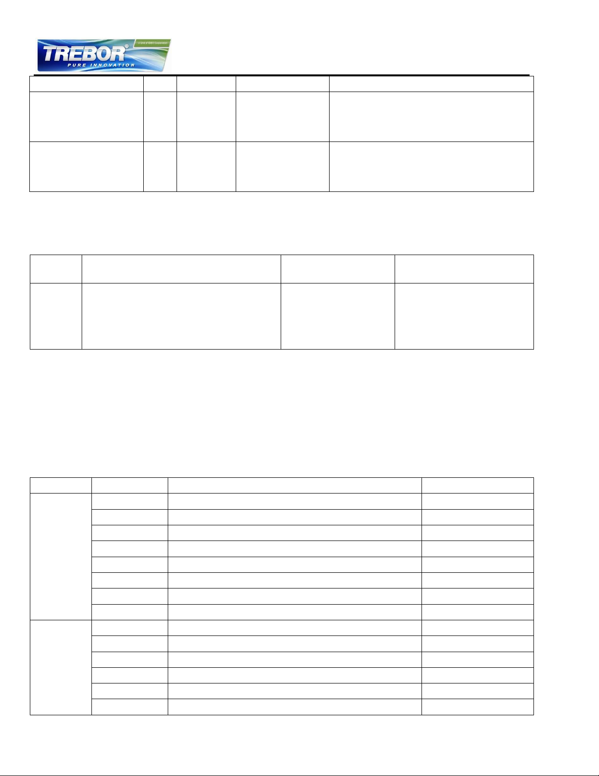
Table 1 lists each part:
REV6 OPERATION / MAINTENANCE MANUAL 5 CONTENTS
Figure 1 – Standard Components (Cables not shown)
Table 1 – Major Component Part List
Page 6
Component
Item
PN
Description
Materials of Construction
Controller
9
98004271
Motor Controller
Standalone Controller
48VDC/600W Power
Panel control for motor speed
Optional PLC control
Motor
10
98004270
600W Motor
Standard 3 meter cables included (not
shown)
FEP Jacket
IP67 rated liquid and dust protected
Product
Description
Included
Additional Required
Items
REV6A0
Pump with PP union nut and 316 SS
bolts
- Pump
- Attachment
Screws
- Pump Manual
- Pump motor
- Pump controller
- Connecting cables
- Power supply
- Fluid port adapters
Seal Type
PN
Part Description
Plant Connection
PTFE Gasket
G12000-10
GROUP;ADPTR;3/4IN PIPE;PTFE GSKT
3/4” weldable pipe
G12F08-10
GROUP;ADPTR;1/2 IN FLR;PTFE GSKT
1/2” flare
G12F12-10
GROUP;ADPTR;3/4FLR;PTFE GSKT;PVDF NUT
3/4” flare
G12F16-10
GROUP;ADPTR;1IN FLR;PTFE GSKT
1” flare
G12P12-10
GROUP;ADPTR;3/4 FNPT;PTFE GSKT
3/4” female NPT
G12PL12-10
GROUP;ADPTR;3/4 PRIMELOCK;PTFE GSKT
3/4” PrimeLock
G12T12-10
GROUP;ADPTR;3/4T;PTFE GSKT
3/4” tube stub
G12X12-10
GROUP;ADPTR;3/4 PILLAR;PTFE GSKT
3/4” Pillar
FFKM O-ring
O12000
GROUP; ADPTR; 3/4 IN PIPE; FFKM O-RING
3/4” weldable pipe
O12F08
GROUP;ADPTR;1/2IN FLARE;FFKM O-RING
1/2” flare
O12F12
GROUP;ADPTR;3/4IN FLARE;FFKM O-RING
3/4” flare
O12F16
GROUP;ADPTR;1IN FLARE;FFKM 0-RING
1” flare
O12P12
GROUP;ADPTR;3/4IN FNPT;FFKM O-RING
3/4” female NPT
O12PL12
GROUP;ADPTR;3/4IN PRMLCK;FFKM O-RING
3/4” PrimeLock
The Rev6 can be ordered as an individual pump to replace a current installation. In order to have a fully
functioning unit (i.e., for a new installation) a motor, controller, connecting cables, power supply and
fluid port adapters are required. The pump will not operate without a motor and controller.
Table 2 – Standard System Configurations
Wide varieties of industry standard fluid interfaces are available in the fluid port adapter. The fluid port
adapter assures seamless fit between plant infrastructure and the Rev6 pump. All fluid port adapters
are manufactured out of ultrapure PFA for the highest chemical compatibility and purity and can be
used interchangeable between any Rev6 pump.
Two seal types are available on the pump side. The first is a PTFE gasket seal to ensure chemical
compatibility. The second is a semiconductor grade FFKM o-ring seal. The seal is specifically designed
to maintain sealing characteristics even at elevated temperatures. The types of adapters currently
available are shown below.
Table 3 – Fluid Port Adapters
REV6 OPERATION / MAINTENANCE MANUAL 6 CONTENTS
Page 7
Seal Type
PN
Part Description
Plant Connection
O12T12
GROUP;ADPTR;3/4IN TUBE;FFKM O-RING
3/4” tube stub
O12X12
GROUP;ADPTR;3/4IN PILLAR;FFKM O-RING
3/4” Pillar Super 300
If additional fluid connections are needed, contact your Trebor representative for options
All flare nuts are constructed of PVDF. PFA nuts are available on request.
PrimeLock and Pillar Super 300 are trademarks of Entegris, Inc. and Nippon Pillar Packing Co. LTD,
respectively.
Accessory
PN
Description
Comments
Power
Cable
98004272-01
CABLE;POWER;0.5m;REV6
PVC Jacket
Circular AMP and D-Sub Plastic
Connectors
98004272-02
CABLE;POWER;3m;REV6
98004272-03
CABLE;POWER;5m;REV6
98004272-04
CABLE;POWER;7m;REV6
98004272-05
CABLE;POWER;10m;REV6
Sensor
Cable
98004273-01
CABLE;SENSORS;0.5m;REV6
PVC Jacket
Circular AMP and D-Sub Plastic
Connectors
98004273-02
CABLE;SENSORS;3m;REV6
98004273-03
CABLE;SENSORS;5m;REV6
98004273-04
CABLE;SENSORS;7m;REV6
98004273-05
CABLE;SENSORS;10m;REV6
Power
Supply
98004274
POWER SUPPLY;48V;REV6
TSP-600-148-M
(M=Modified design from Traco)
Output: 48 VDC, 600 W
Input: 85-265 VAC (auto detect)
CE, CB, UL, CSA, SEMI F47
Air Cooling
Module
98004282
MODULE;AIR COOLING;REV6
PP (+40% Talc)
NPT 1/4” Connection
1-3 bar (14-43 psi) – 100 LPM @ 1 bar
Additional components are available for the Rev6. Extension cables to pair the controller to the pump
are available at several different lengths. A sensor cable and power cable are needed for each
motor/controller pair. A 48V power supply is also needed for the motor and controller. The specific
accessories and part numbers are listed below. See 2.2 below for descriptions and diagrams of
different pump setups.
Table 4 – Additional Accessories
2.2 Standard System Configurations
2.2.1 Pump Only Configuration
The Rev6 pump can be purchased without a motor or controller to replace a pump in an existing
installation. The Rev6 is a drop-in replacement for the Levitronix BPS-600. This configuration comes
with the assembled pump and four 316 stainless steel screws to attach the pump to the motor.
2.2.2 Stand-Alone System Configuration
The stand-alone pump system configuration (Figure 2) consists of a controller with an integrated user
panel to set the speed manually. The speed is adjusted using the buttons on the control panel and
automatically stored in the internal EEPROM of the controller. As an alternative, the pump speed can
also be set with an external analog signal.
REV6 OPERATION / MAINTENANCE MANUAL 7 CONTENTS
Page 8
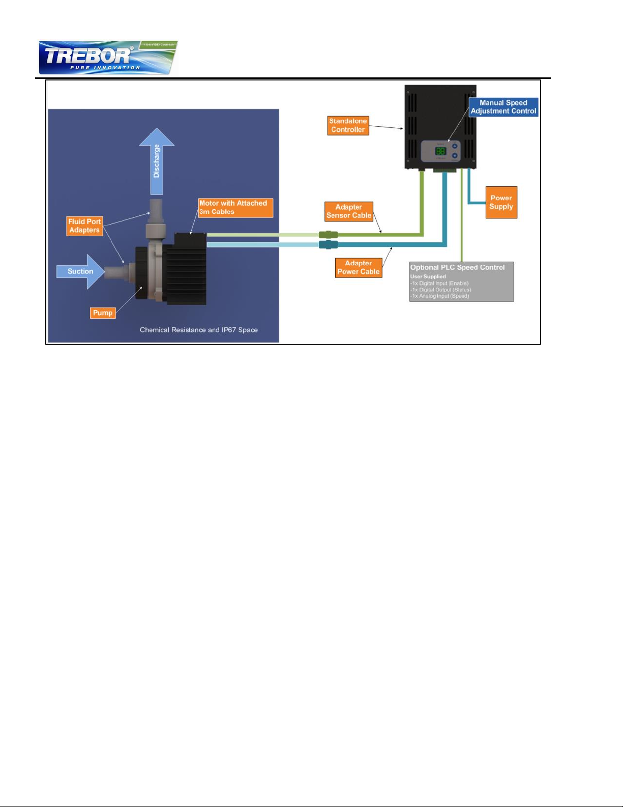
Figure 2 – Standard System Configuration for Standalone Control (Rev6A1)
All components in an orange box in Figure 2 are required for an operable system. The adapter cables
(sensors and power), fluid port adapters, and power supply are sold as separate line items.
REV6 OPERATION / MAINTENANCE MANUAL 8 CONTENTS
Page 9
Controller usage
Indoor
Motor with pump usage
Indoor/Outdoor
Altitude
Up to 2000 m
Operating ambient temperature
0 to 40°C
Storage ambient temperature
(Extremes for transportation)
-20 to 80°C
Operating humidity range
15 to 95% relative humidity (non-condensing)
Storage humidity range
(Extremes for transportation)
15 to 95% relative humidity (non-condensing)
Normal storage conditions
Ambient temp.: 20 to 30 °C
Relative humidity: 50% (non-condensing)
Acceptable DC supply fluctuations
±5% of nominal voltage
Transient over-voltages typically
present on the mains supply
Surge immunity according to EN 61000-4-5
(tested together with certified AC/DC power supply)
Pollution degree
2
9000 RPM
8000 RPM
7000 RPM
6000 RPM
5000 RPM
4000 RPM
0.0 2.5 5.0 7.5 10.0 12.5 15.0 17.5 20.0
0
10
20
30
40
50
0.0
0.5
1.0
1.5
2.0
2.5
3.0
3.5
0 10 20 30 40 50 60 70 80
GPM
PSI
bar
LPM
Specific gravity = 1 g/cm3
Viscosity = 1 cP
Liquid Temp.: 23°C
2.3 General Environmental Conditions
Table 5 – Environmental Conditions for Pump System
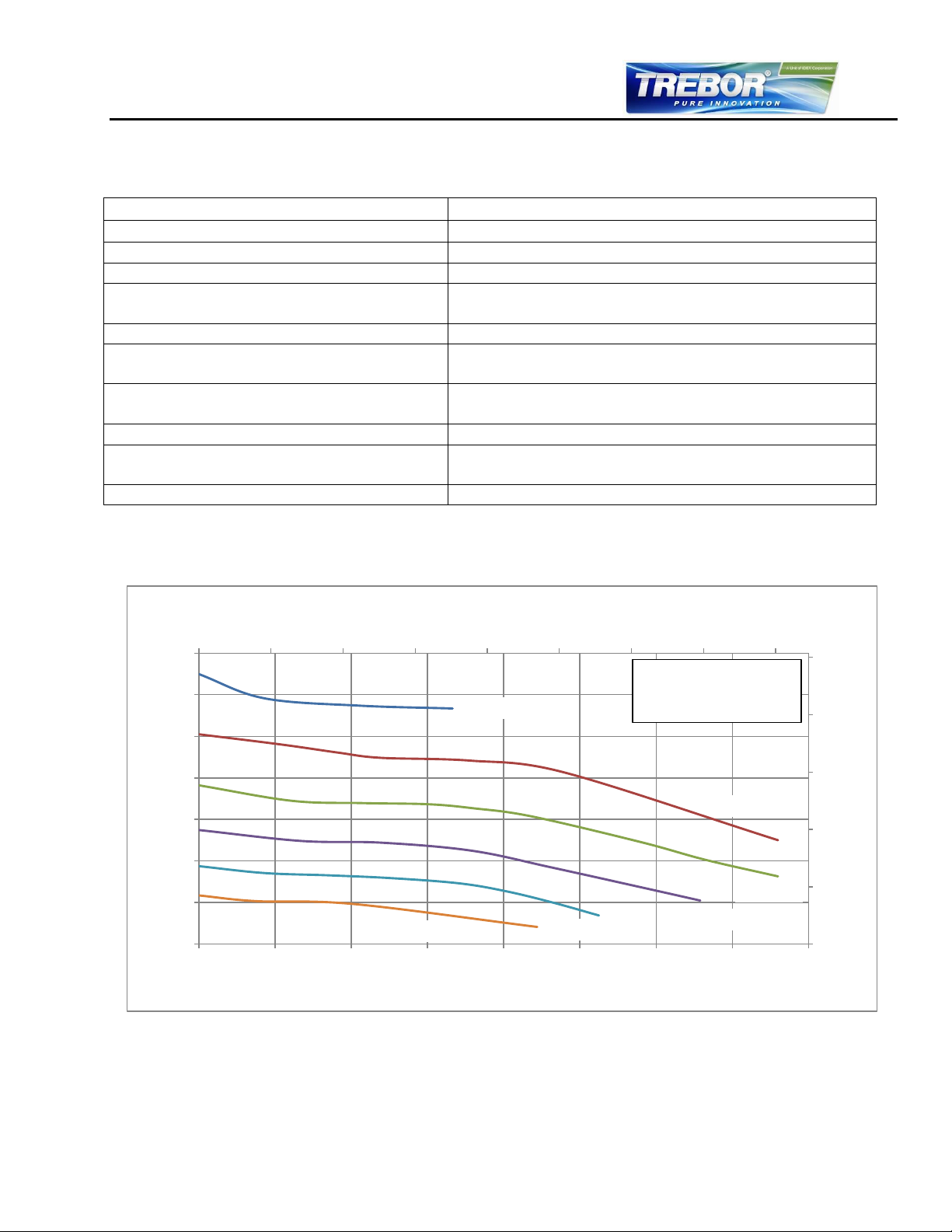
2.4 Pump Performance Curves
2.4.1 Pressure-Flow Curves
Figure 3 – Rev6 Flow vs Diff Pressure Curves
REV6 OPERATION / MAINTENANCE MANUAL 9 CONTENTS
Page 10
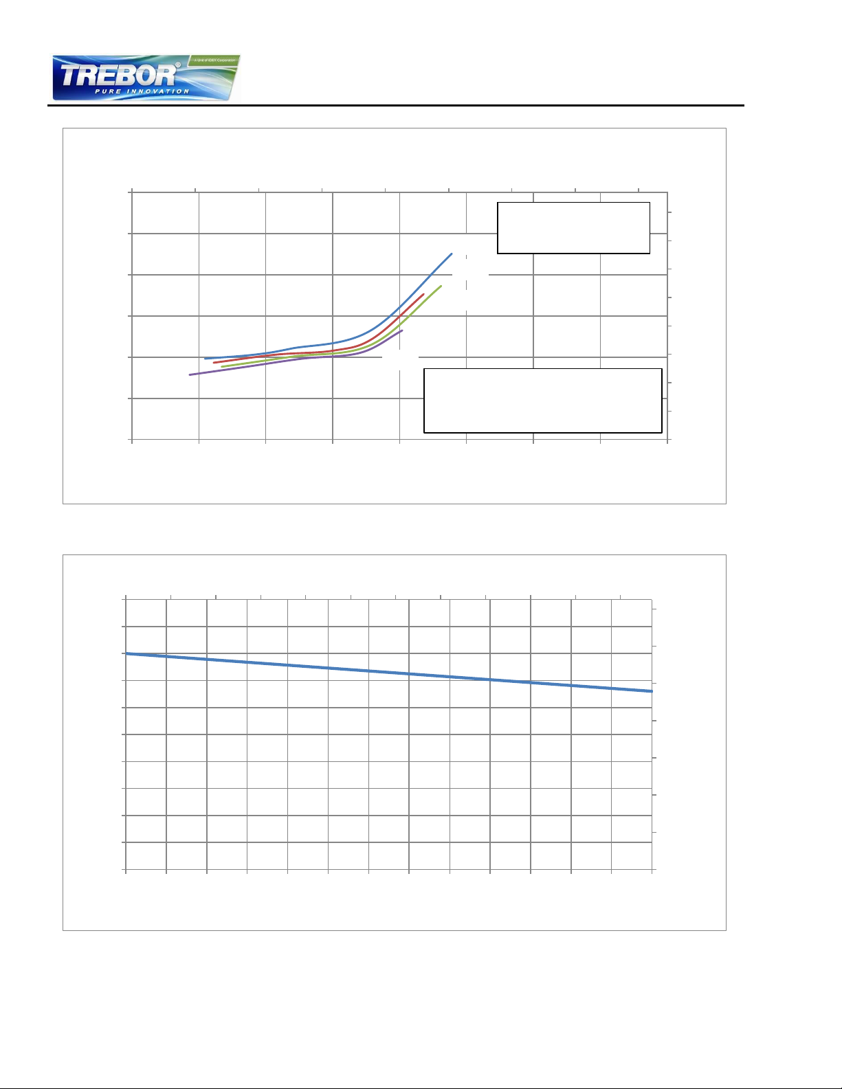
2.4.2 NPSHr Curves
8000
7000
6000
5000
0.0 2.5 5.0 7.5 10.0 12.5 15.0 17.5 20.0
0
1
2
3
4
5
6
7
8
0.0
0.1
0.2
0.3
0.4
0.5
0.6
0 10 20 30 40 50 60 70 80
GPM
PSI
bar
LPM
NPSHr Criteria ≡ The min. absolute inlet pressure
where the pump pressure is reduced by 3%
- Limitation is due to the axial limit of the
impeller
77 87 97 107 117 127 137 147 157 167 177 187
0
20
40
60
80
100
120
140
0
1
2
3
4
5
6
7
8
9
10
25 30 35 40 45 50 55 60 65 70 75 80 85 90
°F
PSI
Maximum Static Pressure
bar
°C
Fluid Temperature
Specific gravity = 1 g/cm3
Viscosity = 1 cP
Liquid Temp.: 20°C
Figure 4 – NPSHr Curves
2.4.3 Maximum Static Pressure vs. Fluid Temperature
Figure 5 – Maximum Static Pressure Allowed vs. Fluid Temperature
REV6 OPERATION / MAINTENANCE MANUAL 10 CONTENTS
Page 11
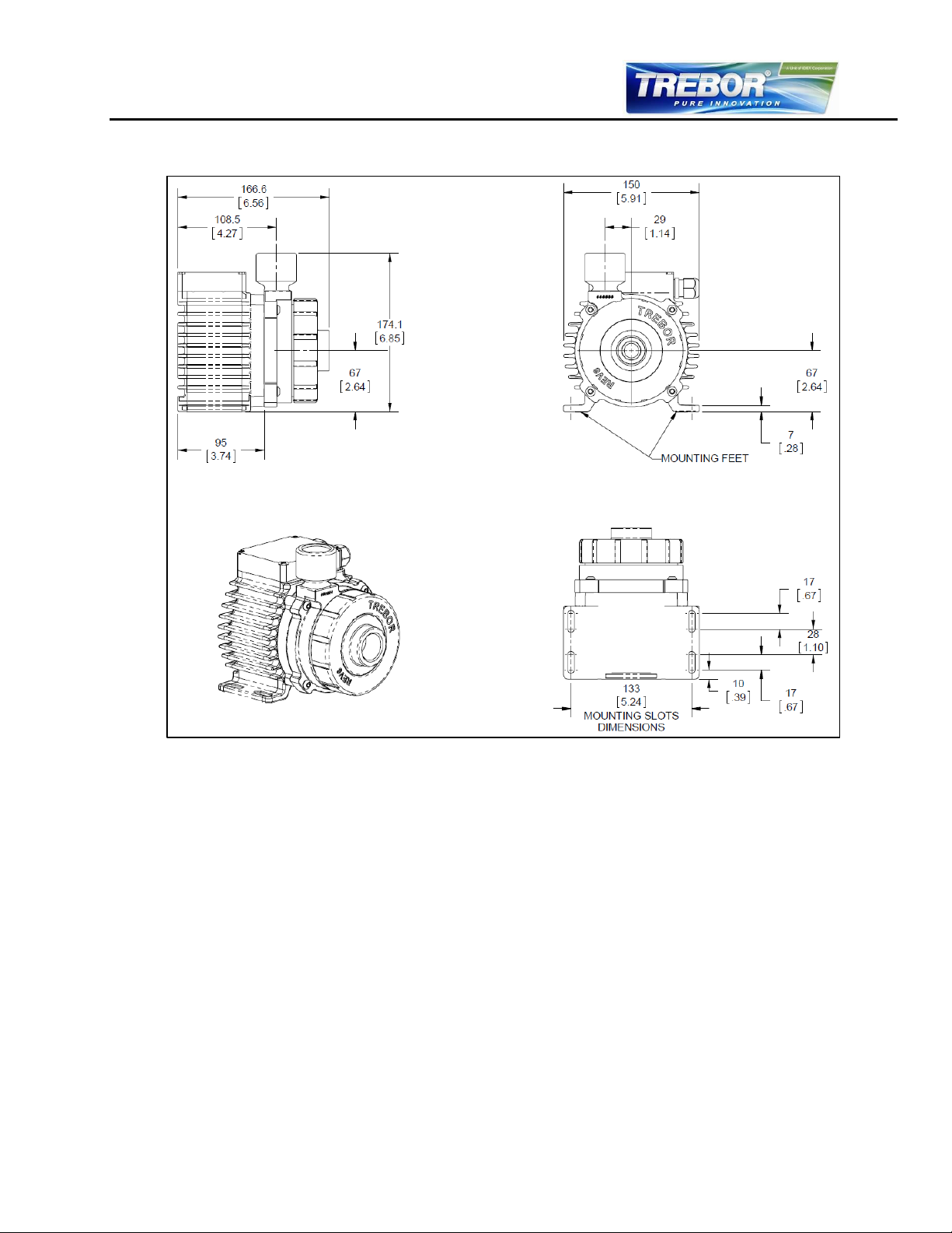
2.5 Basic Dimensions of Main Components
All dimensions are given in mm and inches with the inch measurement in brackets.
Figure 6 – Basic Pump Dimensions
REV6 OPERATION / MAINTENANCE MANUAL 11 CONTENTS
Page 12
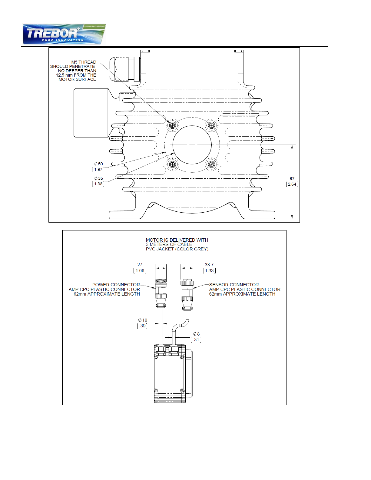
Figure 7 – Alternative Mounting Position
Figure 8 – Cable and Connector Specifications
REV6 OPERATION / MAINTENANCE MANUAL 12 CONTENTS
Page 13
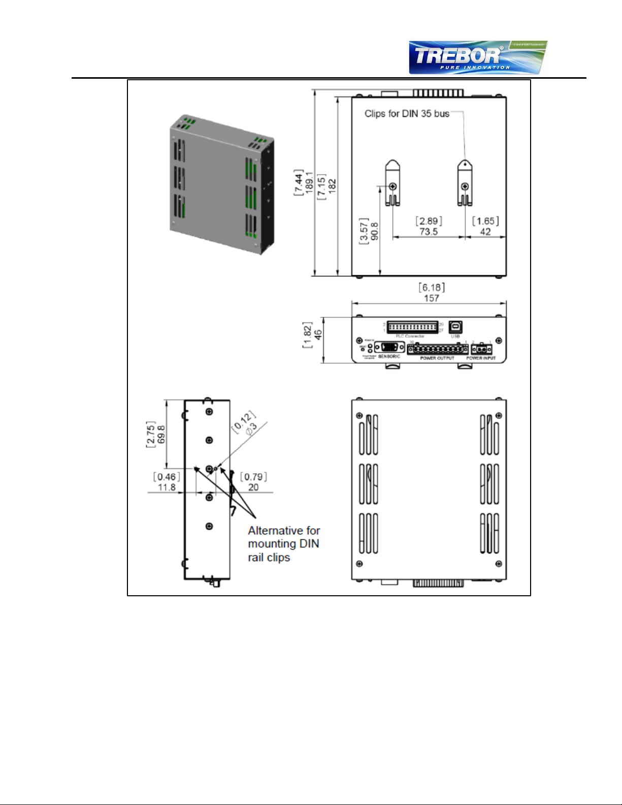
Figure 9 – Controller Basic Dimensions
2.6 Air Cooling Module
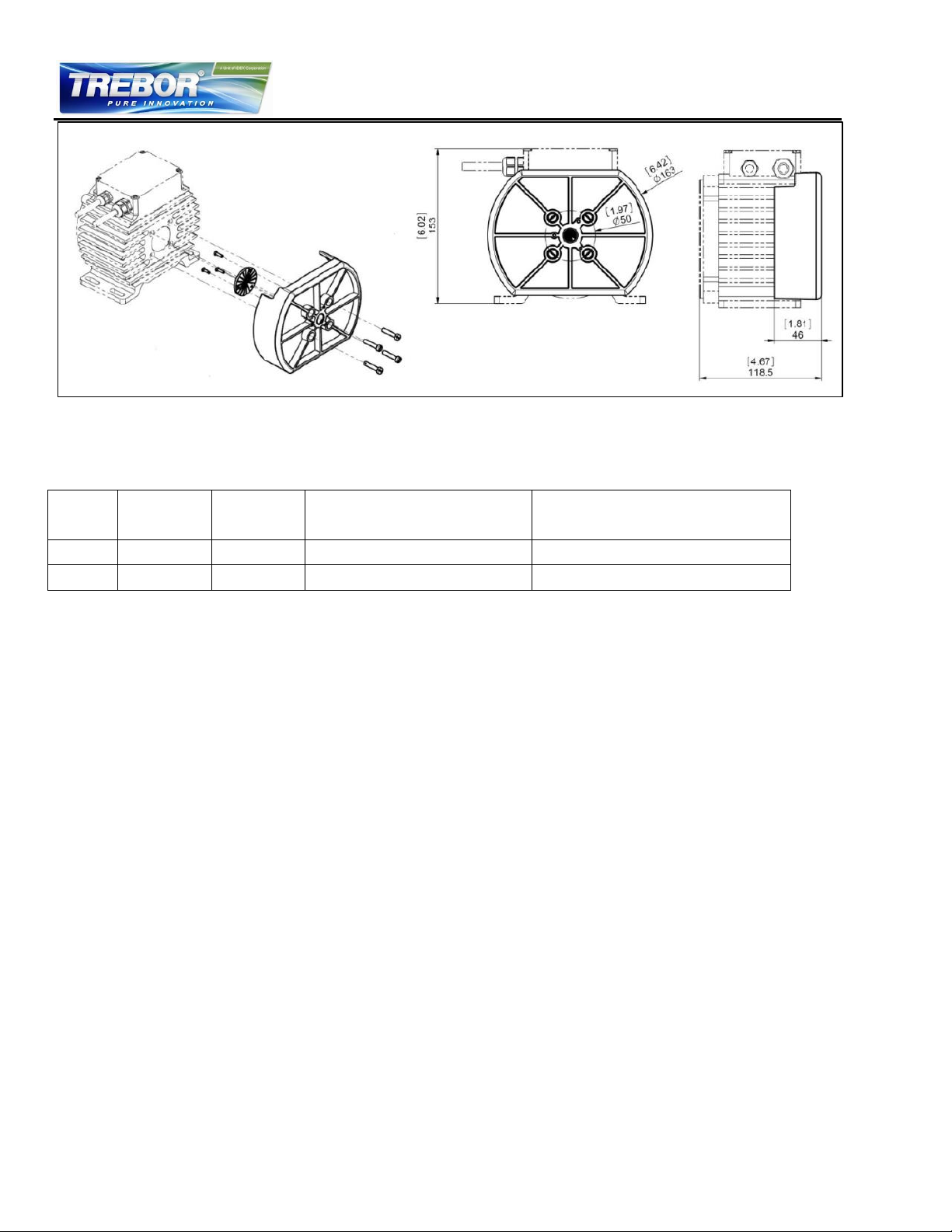
The motor can be cooled by using the air-cooling module. This module attaches to the back of the
pump motor with four bolts. Section 3.4.1 gives more information on motor cooling requirements. Figure
10 shows the dimensions of the motor with the attached air-cooling module.
REV6 OPERATION / MAINTENANCE MANUAL 13 CONTENTS
Page 14
Cable
Jacket
Sensor
Cable OD
Power
Cable OD
Minimum Bending Radius
Permanent Installation
Minimum Bending Radius
Occasional Cable Movemvent
FEP
6.6mm
8.4mm
7x Cable OD
15x Cable OD
PVC
7.2mm
10.0mm
6x Cable OD
12x Cable OD
Figure 10 – Motor dimensions with attached air-cooling module.
2.7 Cable Minimum Bend Radius
REV6 OPERATION / MAINTENANCE MANUAL 14 CONTENTS
Page 15
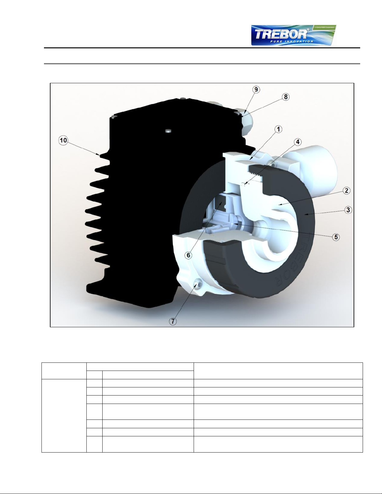
System
Component
Item
Materials
No
Description
Pump
1
Pump Casing
PTFE
2
Inlet Housing
PTFE
3
Union Nut
Polypropylene
4
Static Sealing O-ring of
Pump Casing
FFKM
5
Impeller
PFA
6
Rotor Magnet
NdFe (rare-earth material)
7
4 screws for pump-motor
housing
316 stainless steel
3 ENGINEERING INFORMATION
3.1 Sealing and Material Concept
REV6 OPERATION / MAINTENANCE MANUAL 15 CONTENTS
Figure 11 – Sealing and Material Concept
Table 6 – Materials Used in the Pump and Motor
Page 16
System
Component
Item
Materials
No
Description
Motor
8
Flat gasket for motor
housing
FKM (FPM)
9
Cable strain relief bushing
PVDF, cable jacket is PVC
10
Motor housing
ETFE coating, waterproof (IP-67)
Coils and electromagnetic circuit potted with an
epoxy compound (UL94 V0).
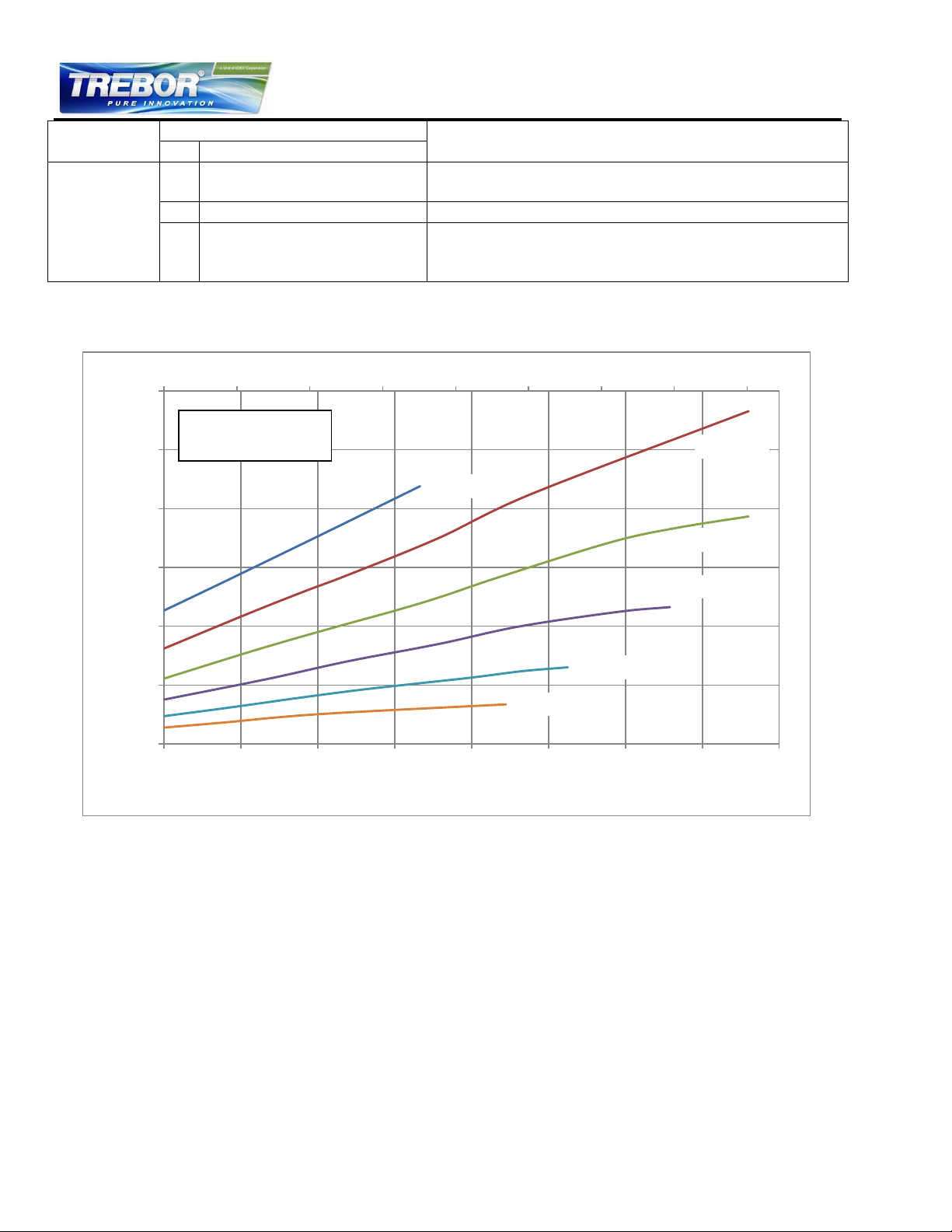
9000 RPM
8000 RPM
7000 RPM
6000 RPM
5000 RPM
4000 RPM
0.0 2.5 5.0 7.5 10.0 12.5 15.0 17.5 20.0
0
100
200
300
400
500
600
0 10 20 30 40 50 60 70 80
Watts
LPM
Specific gravity = 1 g/cm3
Viscosity = ~ 1 cP
Liquid Temp.: 23°C
3.2 Power Consumption
Figure 12 – Electrical Power Consumption
REV6 OPERATION / MAINTENANCE MANUAL 16 CONTENTS
Page 17
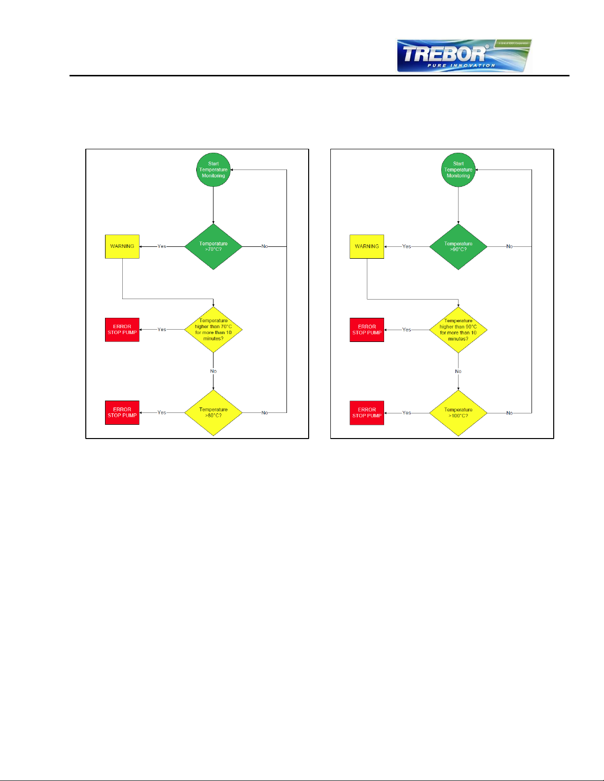
Figure 13 – Controller Temperature Monitoring
Figure 14 – Motor Temperature Monitoring
3.3 Temperature Monitoring
To avoid overheating of the system, the controller and motor temperatures are monitored. If the
controller temperature exceeds 70°C (158°F) or the motor temperature 90°C (194°F) for longer than 10
minutes, the system goes into an error state and the pump stops. At 80°C (176 F) controller
temperature or 100°C (212°F) motor temperature, the system immediately stops.
REV6 OPERATION / MAINTENANCE MANUAL 17 CONTENTS
Page 18
3.4 Thermal Management
3.4.1 Motor Temperature
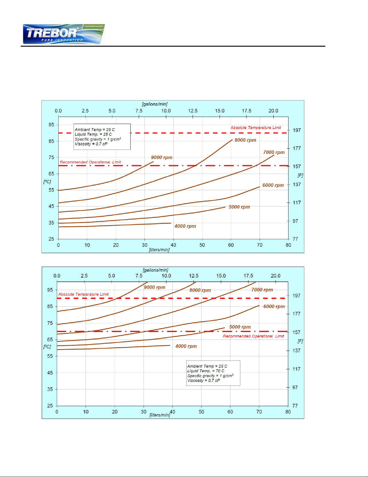
The motor temperature depends on the ambient and liquid temperature, as well as on the hydraulic
operation point. Figure 15 and Figure 16 illustrate the temperature characteristics of the motor
depending on these parameters. For higher fluid temperatures and hydraulic operating points, active
cooling is recommended. The air-cooling module is available from Trebor for this purpose.
Figure 15 - Temperature Curves of the Motor for 25°C Fluid Temperature
(Temperature is measured inside of the motor, contact temperature of surface is below this temperature)
Figure 16 - Temperature curves of the Motor for 70°C Fluid Temperature
(Temperature is measured inside of the motor, contact temperature is below this temperature)
REV6 OPERATION / MAINTENANCE MANUAL 18 CONTENTS
Page 19
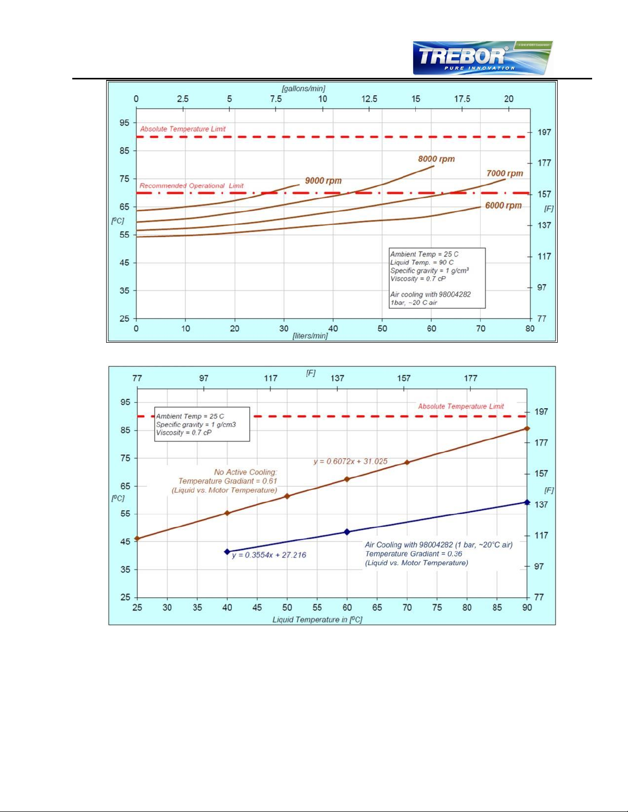
Figure 17 – Temperature Curves of Motor with Air Cooling Module (98004282)
Figure 18 – Fluid Temperature Influence on Motor Temperature
(Measurement at 7000 RPM, 23 LPM but gradients are representative for other operational points)
The above curves are measurements of the motor temperature at certain liquid and ambient
temperatures. Equation 1 shows how to calculate the motor temperature for other liquid and ambient
temperatures based on these curves.
REV6 OPERATION / MAINTENANCE MANUAL 19 CONTENTS
Page 20
Equation 1
In order to account for thermal variations (like ambient temperature, closed chemical cabinets or
corners without ventilations) and to not significantly reduce the MTBF of the motor it is recommended to
keep about 20°C safety margin to the absolute thermal limit of the motor (90°C) when designing the
thermal concept of the pump system.
3.4.2 Controller Temperature
Depending on the ambient temperature and the placement of the controller, additional cooling may be
required (see Figure 19). To improve cooling of the controller, place the device into a moving air
stream. If the controller is mounted in a compact area or adjacent to additional heat sources (e.g. a 2nd
controller), ensure that there is sufficient ventilation.
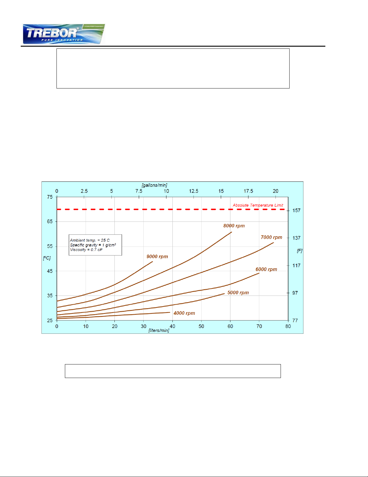
Figure 19 - Temperature Curves of Controller vs. Flow and Speed
The above curves are measurements of the controller temperature at 25°C ambient. Equation 2 shows
how to calculate the controller temperature for other ambient temperatures based on this curve.
REV6 OPERATION / MAINTENANCE MANUAL 20 CONTENTS
Equation 2
Page 21

3.5 Hydraulic Circuit Design
Follow these general design rules for the hydraulic circuit will yield more robust pump operation and
optimum priming:
1. The general rule for optimum priming behavior is to minimize the pressure drop in the inlet
circuit and avoid negative pressure at the inlet of the pump.
2. Minimize tubing length and maximize the tubing ID at the inlet of the pump. This reduces the
pressure drop and the tendency of cavitation.
3. Avoid any restrictions, valves, elbows, bended tubing and sharp edges at the inlet circuit of the
pump, which could potentially cause cavitation resulting in gas bubble collection in the pump
and potential priming loss.
4. Place the pump at the lowest point of the hydraulic circuit. Optimum is as much as possible
below a tank or reservoir. This optimizes priming behavior and removal of gas bubbles.
5. Keep the liquid level in the reservoir as high as possible, which increases the inlet pressure of
the pump and minimizes fluid heating.
6. In general, the pump system placement and circuit shall be designed such that gas bubbles can
leave the pump housing so the pump remains primed.
7. To minimize fluid heating, the overall pressure drop in the hydraulic circuit should be reduced as
much as possible.
8. Deadhead operation (pump operation when the discharge valve is closed) should be avoided. It
can cause heat-up of the liquid.
9. Optimization of the fluid circuit becomes more important as the fluid temperature increases due
to the higher cavitation tendency of the liquid.
Contact Trebor (see Section 8) for additional considerations and support on the hydraulic circuit design.
REV6 OPERATION / MAINTENANCE MANUAL 21 CONTENTS
Page 22
Item
Interface
Description
1
“SENSORIC”
Position, field and temperature sensor signals from motor
Torque spec. for tightening of connector screws: Min. = 0.4, Max. = 0.6 Nm
2
“USER INTERFACE”
1 Digital Input
Galvanic isolation with optocoupler
Lowest input voltage for high level detection: min. 5 V; typical 24 V /
16 mA; maximum 30 V / 20 mA
Highest input voltage for low-level detection: max. 0.8 V
Minimum input resistance: RIN = 2.2 kΩ
1 Digital Output
Galvanic isolation with relay
Relay: 1A / 30VDC, 0.3A / 125 VAC
1 Analog Input
Analog current input: 4 – 20 mA
450 Ω shunt input
3
“POWER OUTPUT”
Drive and bearing currents of the motor
Torque spec. for tightening of connector screws on motor side: Min. = 0.5 Nm, Max. = 0.6
Nm
4
“POWER INPUT”
DC power input
Torque spec. for tightening of connector screws on motor side: Min. = 0.5 Nm, Max. = 0.6
Nm
4 INSTALLATION
4.1 Electrical Installation of Controller
4.1.1 Overview
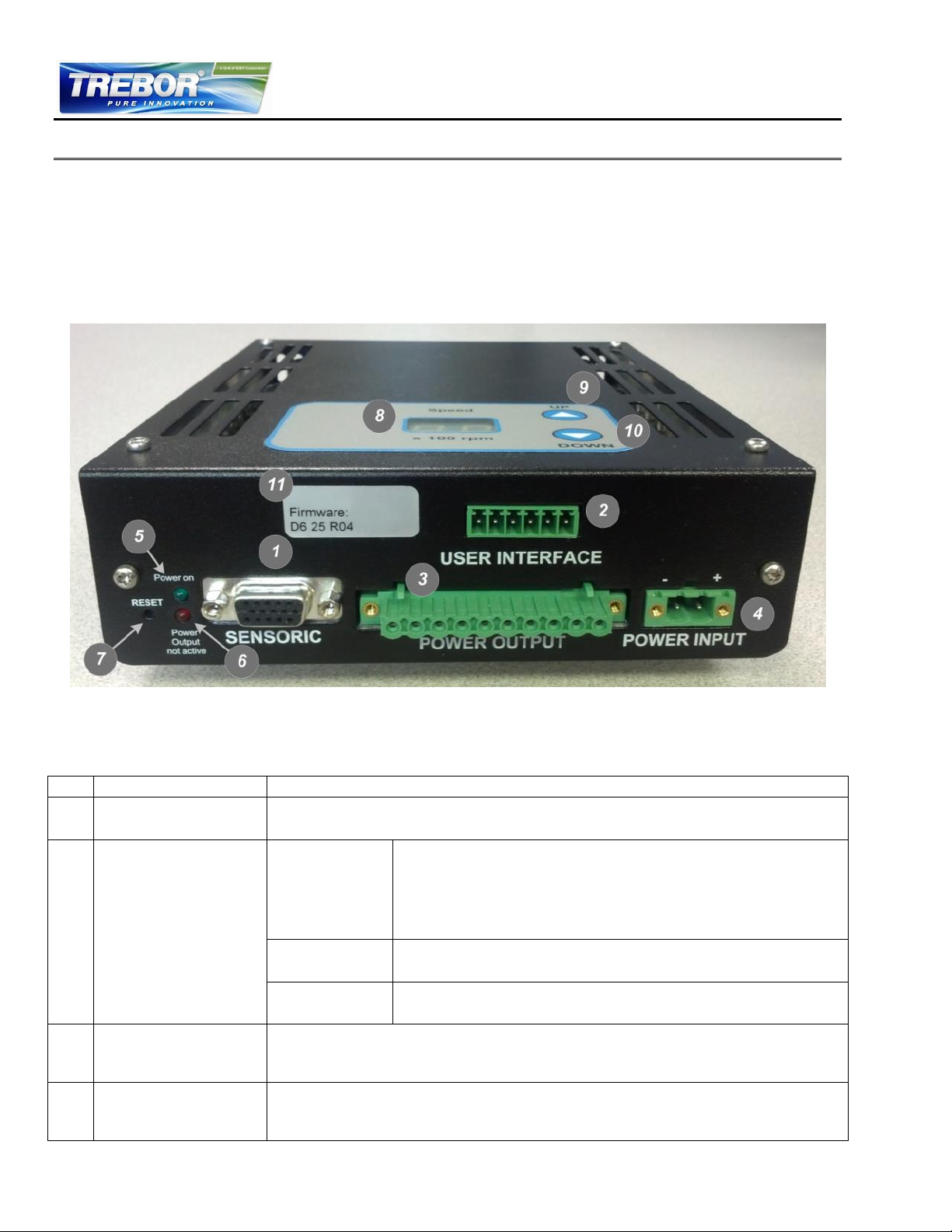
The Rev6 standalone controllers have signal processor controlled power converters with four switched
inverters for the drive and the bearing windings of the motor. The signal processor allows precise
control of pump speed and impeller position. Figure 20 shows the interfaces of the standalone
controller with standalone and minimal PLC functions.
Figure 20 – Overview of the Standalone Controller Interface
Table 7 – Interface Description of Standalone Controller
REV6 OPERATION / MAINTENANCE MANUAL 22 CONTENTS
Page 23
Item
Interface
Description
5
“Power on” Green LED
LED is on if supply voltage of signal electronics is present.
6
“Power Output not
active” Red LED
Red LED is off if the switched output stage of the controller is enabled. If the LED is on, the
bearing and drive coils of the motor carry no current.
7
“RESET” Button
Reset button of the controller stage. The button is recessed and can be activated using a
small pointed object.
8
2-Digit Display “Speed”
Rotational speed display in 100 RPM
9
“UP” Button
Button for speed increasing
10
“DOWN” Button
Button for speed decreasing
11
“Firmware” Label
Firmware version and revision number
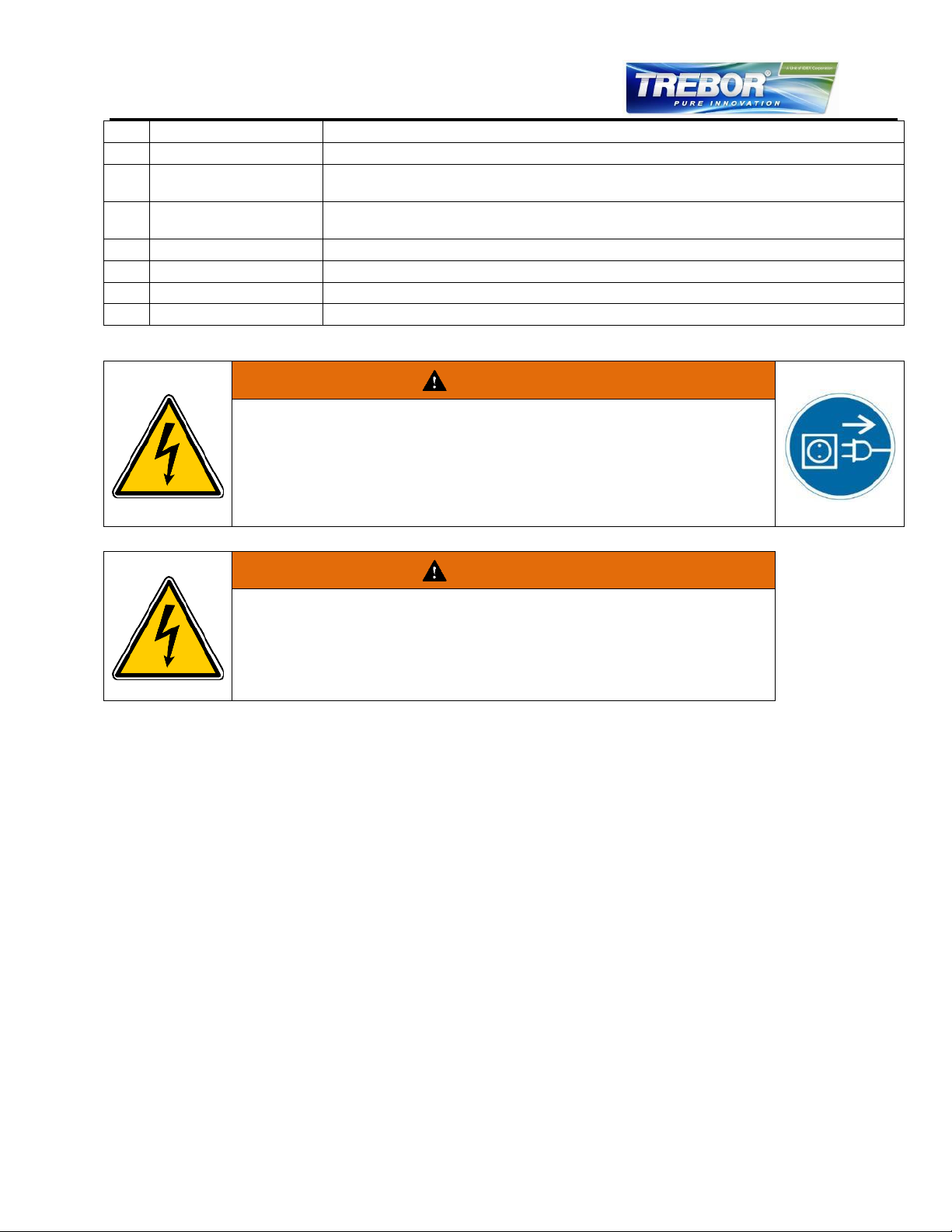
WARNING
Hazardous voltage may be present.
Always isolate the electrical power supply before making or changing connections to
the unit.
In case of the usage of an inadequate AC/DC power supply, mains voltages may be
present (even if the system is designed for 48VDC). The usage of a galvanic
separated power supply, which is certified by a 3rd party (UL or CE), is highly
recommended.
WARNING
Hazardous voltage may be present.
The controller housing must be properly grounded and placed in a spill protected
environment. Use one of the DIN-rail screws on the back side of the controller
housing.
Do not use different and longer screws, which may result in short-circuits within the
controller.
4.1.2 General Installation Instructions
1. The controller casing must be grounded. The screws of the DIN-rail bracket can be used for
grounding.
2. Connect the two motor connectors (“POWER OUTPUT” and “SENSORIC”) to the controller.
3. Connect the controller type specific connectors: see Section 4.1.3 for standalone operation with
the Standalone Controller.
4. The pump system requires 48 VDC supply voltage at a maximum power of 600 W. Depending
on the desired hydraulic operational point, smaller power supplies may be used. Also, a larger
supply may be used to power several pump systems simultaneously. Figure 12 shows the
power consumption depending on the pressure and flow rate. Contact Trebor for additional
information on a power supply solution.
5. Connect the DC power supply connector with the cable (included with the controller). Make sure
that the polarity is correct (see Figure 20) and that AC/DC power supply is off.
6. To secure the connectors, tighten all retaining screws according to the torque specifications in
Table 7.
4.1.3 Electrical Installation of Standalone Operation
For standalone operation, the controller is disabled when power is turned on. It can be enabled
manually by pressing the “UP” button on the display. If the controller will be enabled automatically when
power is applied, the “ENABLE” pin on the “USER INTERFACE” connector (see Table 7) has to be
active (typically 24V).
REV6 OPERATION / MAINTENANCE MANUAL 23 CONTENTS
Page 24
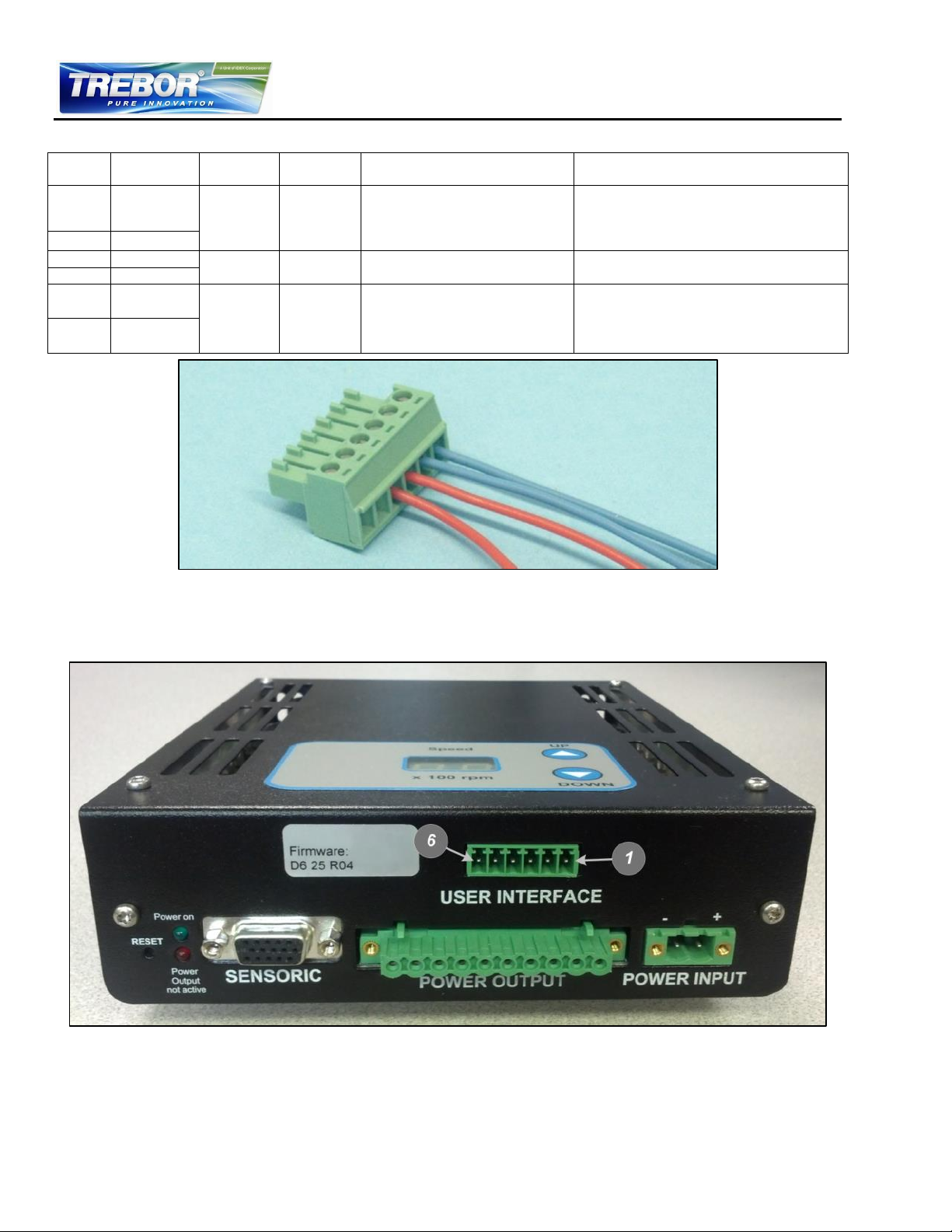
Pin
Pin
Number
Function
Name
Levels
Note
Signal
5
Analog In
Reference
Speed
4-20 mA = 0-10000 rpm
Upper Speed Limit = 9000 rpm
≈ 18.4 mA
Lower Speed Limit = 300 rpm
Direct connection, no protection.
Galvanic isolation on the user side is
required.
Ground
6
Signal
3
Digital In
Enable
24 V → active
0 V → not active
Needed to enable the system with an
external signal.
Ground
4
Signal
1
Digital
Out
Status
Relay closed → active, system
on
Relay open → not active,
system off
This signal indicates if the system is
active.
Ground
2
Table 8 – Description of “USER INTERFACE” Connector
Figure 21 – “USER INTERFACE” Connector
- Delivered with Controller
- Connector Type: AK1550/06-3.81-Green
REV6 OPERATION / MAINTENANCE MANUAL 24 CONTENTS
Figure 22 – “USER INTERFACE” Pin Numbering
Page 25
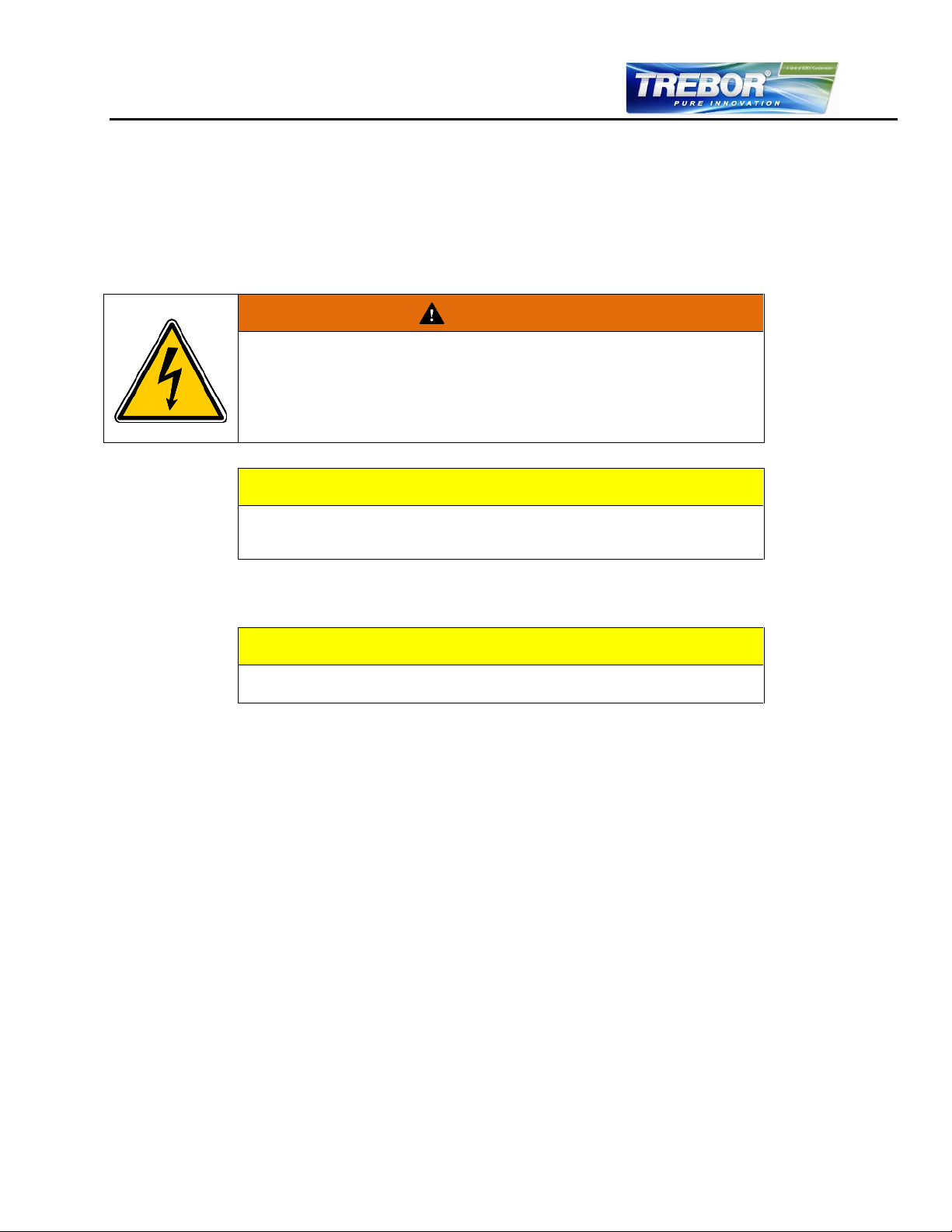
WARNING
Hazardous voltage may be present.
In order to avoiding fluid spills shorting mains or other voltages within the
controller, place the controller in a spill-protected environment (for example
protected electronic cabinets).
If explosive flammable gases are present, place the controller in an explosionproof cabinet.
CAUTION
Make sure the controller is mounted in a position that allows free air circulation
around the controller. A minimum distance of 10cm (4”) to other objects above or
below the controller casing is recommended.
CAUTION
Use only 3.5 x 6.5mm self-tapping screw for the fixation of the Din-Rail brackets.
The controller may be damaged if other screws are used!
4.2 Mechanical Installation of the Pump/Motor
The motor can be fixed with four screws on the motor feet (see Figure 6)
As an alternative the motor can be mounted with four screws on the back (see Figure 7)
The motor can be mounted in either the horizontal or the vertical position
Each motor is identified with a unique serial number. This serial number consists of a series of 6
digits where the 5th and the 6th digit represent the manufacturing year.
4.3 Mechanical Installation of the Controller
Use the Din-Rail bracket to mount the controller.
If no forced air-cooling is used, mount the controller in upright position.
The Din-Rail brackets can also be mounted on the controller side according to Figure 9
4.4 Mechanical Installation of Adapter/Extension Cables
For connecting the motor to the controller, use adaptor cables 98004272-## (for power cable) and
98004273-## (for sensor cable) (see Table 4 for details).
REV6 OPERATION / MAINTENANCE MANUAL 25 CONTENTS
Page 26
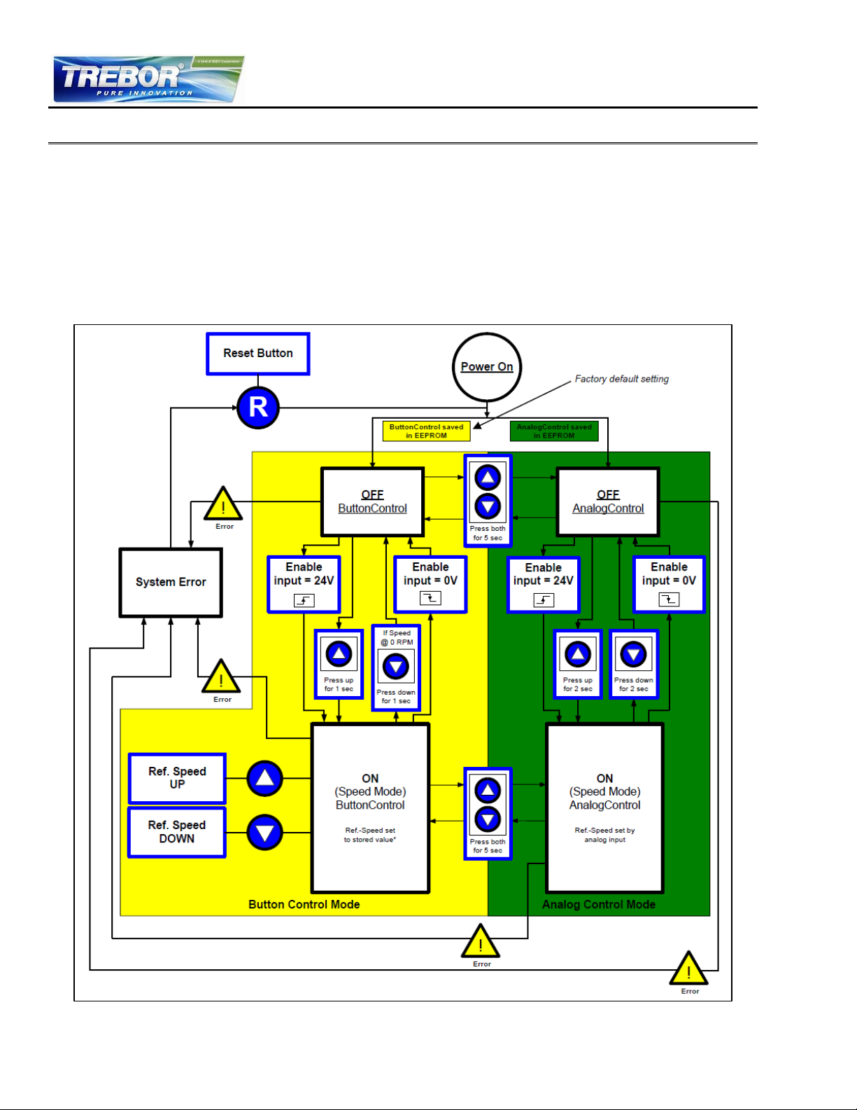
5 OPERATION
5.1 System Operation with Standalone Controller
5.1.1 State Diagram of Standalone Controller
The standalone controller allows operation with manual speed setting (Button Control Mode) as well as
extended operation with analog speed setting (Analog Control Mode). Figure 23 shows the state
diagram, which can be controlled with the manual buttons and the signals on the “USER INTERFACE”
connector. The operation mode can be chosen by pressing the “UP” and “DOWN” buttons
simultaneously for five seconds. For the standard firmware, D6.25, the default setting from the factory is
“Button Control Mode”.
(Description is for firmware D6.25 with Revision > 01, for other configurations refer to alternate firmware documentation)
Figure 23 - State Diagram for Standalone Controller Operation
REV6 OPERATION / MAINTENANCE MANUAL 26 CONTENTS
Page 27

5.1.2 Standalone Operation (Button Control Mode)
When applying power the system defaults into the “Button Control Mode” and goes into the
status “OFF Button Control” according to Figure 23. Levitation is disabled and the display
indicates “OF”.
Levitation can be enabled by pressing the “UP” button for 1 second (display shortly indicates
“ON”) or by activating (typically 24V) the “ENABLE” pin on the “USER INTERFACE” connector
(see Table 8). The system goes then into the status “ON Button Control” and is running at the
speed, which is stored in the EEPROM.
The speed can be changed by pressing accordingly the “UP” and “DOWN” buttons. As long as
the digits on the display are blinking, the “set speed” is shown. As soon as blinking stops the
actual speed is shown and the “set speed” is stored in the EEPROM of the controller.
The system can be disabled by pressing the “DOWN” button until 0 rpm is achieved. Pressing
further 1 second the “DOWN” button the system disables levitation and shows “OF” on the
display. The system can also be disabled by deactivating (0 V) the “ENABLE” pin on the “USER
INTERFACE” connector (see Table 7). Before disabling the system, the speed is automatically
reduced to 0 rpm and the impeller is properly touched down without grinding the wall.
In case of an error the “RESET” button (see Figure 20) can be used to restart the system or the
power can be switched off and on.
For error analysis, the codes described in Table 9 are displayed (blinking between “Er” and the
according code number).
If the system shall be enabled automatically, when power is applied the “ENABLE” pin on the
“USER INTERFACE” connector (see Table 7) has to be active (typically 24V). When switching
on the power the system is running with the stored speed.
For monitoring purposes, a digital output on the “USER INTERFACE” connector (see Table 7)
indicates the status of the system. When the impeller is rotating the digital output “Status” turns
active.
The digital input “ENABLE” is normally edge-triggered to allow control by digital input and buttons in
order to enable/disable systems simultaneously. An exception is, when the system is powered up or a
system reset occurs: than the system checks the level of the digital input and switches to the desired
state. Hence, on startup, a high level of the digital input “ENABLE” is sufficient to switch on the system
and a transition from low to high is not required.
5.1.3 Extended Operation (Analog Control Mode)
In order to be able to control the pump with external signals, the mode “Analog Control Mode”
has to be set with the display buttons. Press the “UP” and “DOWN” buttons simultaneously for 5
seconds. The display should show the mode change by blinking between the stored speed
value and “An”. The chosen mode is then stored in the EEPROM of the controller. After startup,
the system returns to the operation mode selected previously.
The system and levitation can be enabled/disabled with the digital input on the “USER
INTERFACE” connector (see Table 8). When disabling the running system the speed is
automatically reduced to 0 rpm and the impeller is properly touched down without grinding the
wall. The display is blinking between “An” and ”OF”. Alternatively “UP” button is also able to
switch the system o. Pressing the “DOWN” button will switch the system off.
The speed can be set with an analog signal on the “USER INTERFACE” connector according to
Table 8. It is strongly recommended to use galvanic separated signal values.
For monitoring purposes, a digital output “Status” on the “USER INTERFACE” connector (see
Table 8) indicates the status of the system. When the impeller is rotating the digital output
“Status” turns active.
REV6 OPERATION / MAINTENANCE MANUAL 27 CONTENTS
Page 28
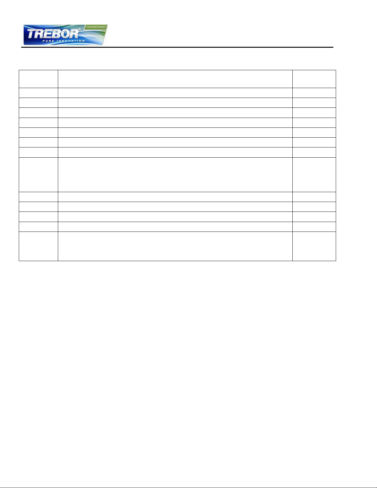
Error
Source
Errors
Error Code
on Display
Motor
No motor
Er 01
Motor
Motor cable (power wires) not connected to controller
Er 02
Motor
Motor cable (sensor wires) not connected to controller
Er 03
Motor
No impeller
Er 04
Controller
Short circuit
Er 05
Controller
Over current in the bearing coils
Er 06
Controller
Over current in the drive coils
Er 07
Controller
DC-Link voltage out of range (< 40 or > 54 V DC)
If the voltage is out of range the system starts to reduce the speed and a warning is generated. When
reaching 0 rpm and the voltage is still out of range the system is disabled and an error is generated. In
case the voltage is again within the range during speed reduction the system switches to normal
operation and no Error is generated.
Er 08
Controller
Communication problems EEPROM Controller
Er 09
Motor
Communication problems EEPROM Motor
Er 10
Controller
Controller temp. over 80°C or more than 10 minutes above 70°C
Er 11
Motor
Motor temp. over 100°C or more than 10 minutes above 90°C
Er 12
Pump
Dry running of pump circuit:
-> Pump keeps running on reduced speed (5000 rpm) -> The system accelerates to the original speed
value when the pump is refilled with liquid. -> Note that the speed is only reduced during dry running if
the pump speed was ≥ 6000 rpm.
Blinking
dots on
display
5.1.4 Error Display on the Integrated Panel
Table 9 - Errors and Warnings with Indication on Standalone Controller Display
- In case of an error the system can only be restarted with a reset or a power supply restart
- Standard firmware is D6.25
- For other configurations of error codes refer to alternate controller or firmware documentation
REV6 OPERATION / MAINTENANCE MANUAL 28 CONTENTS
Page 29
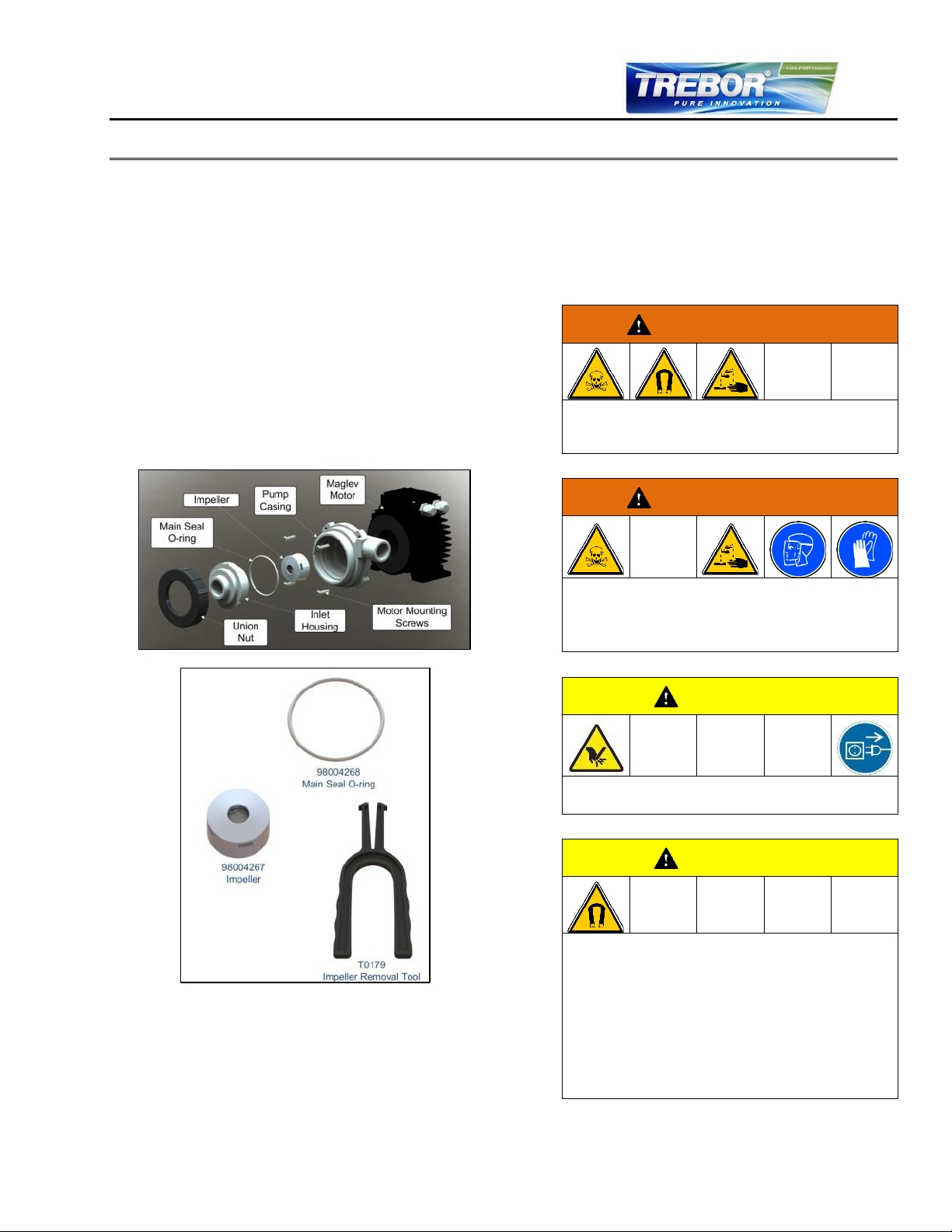
6.2.1 Preparation
Before starting the impeller replacement
procedure, understand the placement and function
of the parts and tools shown in Figure 24 and
Figure 25. The rebuild kit contains these parts and
tools shown in Figure 25. Please verify that you
have the right impellers, and O-rings.
Figure 24 – Labeled Exploded View of Pump
Figure 25 – Rev6 Rebuild Kit
The following warnings and cautions should be
read carefully before starting the replacement of
the impeller.
WARNING
The impeller could splash TOXIC or CORROSIVE
CHEMICALS because of the strong magnetic
forces. Flush the pump housing before opening it.
WARNING
HARMFUL CHEMICALS may be present.
Skin contact and toxic gases may be hazardous to
your health. Wear safety gloves and other
appropriate safety equipment.
CAUTION
The rotating impeller could cause injury. Do not run
the pump system when opening the pump head.
CAUTION
Pay attention to the magnetic forces when handling
the impeller. The attraction of magnetic parts and
particles should be avoided in order to keep the
impeller and the pump head clean and free of
contamination.
6 INSPECTION AND MAINTENANCE
6.1 Impeller Replacement Interval
The impeller has a limited lifetime depending on the type, concentration, and temperature of the fluid
being pumped. Therefore, a preventive periodical exchange of the impeller is recommended. Contact
the Trebor Technical Service Department (see Section 8) for further information on replacement times.
6.2 Impeller Replacement Procedure
REV6 OPERATION / MAINTENANCE MANUAL 29 CONTENTS
Page 30
CAUTION
Use the correct O-Ring type for your process. If
necessary, consult your Trebor representative.
Do NOT twist or roll the O-Ring as this may cause leaking
to occur.
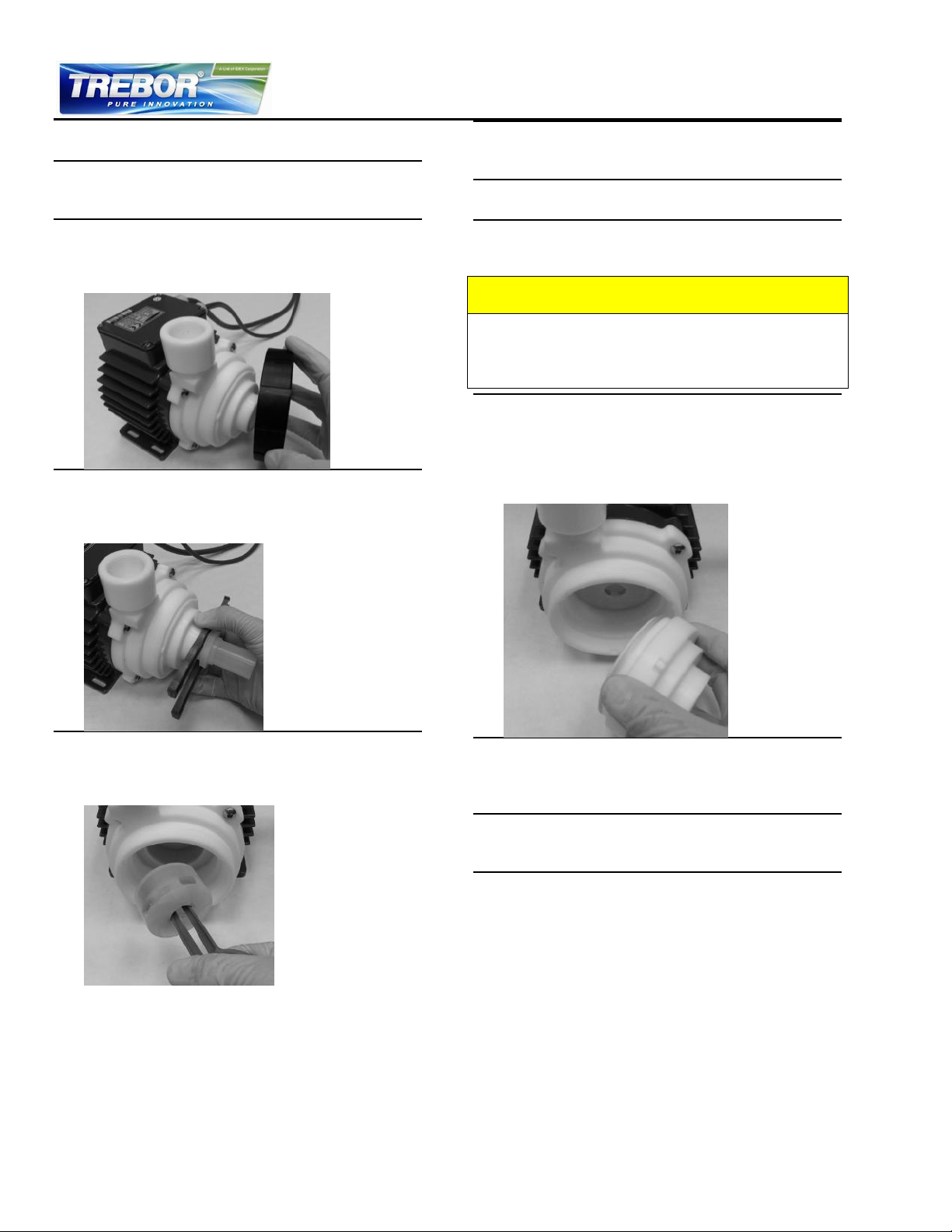
6.2.2 Instructions for Replacement
1. Power down the pump system and remove the
AC power. If necessary, allow the motor housing
to cool down to a workable temperature.
2. Unscrew and remove the union nut. Trebor
provides a tool (T0180 - Tool; Union Nut;
Socket; Rev6) to loosen the union nut or a strap
wrench may be used.
3. Loosen the fluid port adapter enough to insert
the Impeller Removal Tool. Use the tool to pull
the inlet housing and main seal o-ring from the
pump casing.
5. Inspect the wet area of the pump head carefully.
In case of material damage, replace the pump
casing and inlet housing.
6. Place the new impeller into the pump casing
using the Impeller Removal Tool
7. If necessary, remove the existing O-Ring and
gently press the new O-Ring into the shoulder of
the inlet housing.
8. Align the tabs on the inlet housing with the slots
in the pump casing. Press the inlet housing into
the pump casing. Ensure the housing is fully
seated in the casing. The top edge of the inlet
housing should be ~2.5mm (0.1in) above the
casing when fully seated.
4. Gently slide the nose of the Impeller Removal
Tool into the center hole of the impeller.
Squeeze the handle of the tool and pull the
impeller from the pump casing.
REV6 OPERATION / MAINTENANCE MANUAL CONTENTS
9. Carefully tighten the union nut. Tighten by hand
until the union nut is flush with the surface of the
inlet housing. Add an additional 1/8 turn or 8-9
Nm (70-80 in-lbs.) of torque.
10. Start up the system and check if the impeller is
rotating properly and the pump head does not
leak.
11. If the pump head leaks, inspect that the housing
and o-ring are properly pressed into the bottom
of the pump casing. If the o-ring has been
damages, it may be necessary to replace it.
Page 31

7 TROUBLESHOOTING
7.1 Troubleshooting for Operation with Standalone Controller
For troubleshooting and failure analysis with the stand-alone controller the following procedure is
recommended:
Check the status of the LEDs. The specific LEDs are described in Table 7
Use the ERROR codes on the display. The specific error codes are described in Table 9
A digital output on the “USER INTERFACE” connector (“Status”) indicates if the system is
active. However, the source of an error cannot be identified by this signal
REV6 OPERATION / MAINTENANCE MANUAL CONTENTS
Page 32

8 TECHNICAL SUPPORT
For troubleshooting, support and detailed technical information contact
TREBOR
8100 South 1300 West
West Jordan, Utah 84088 USA
Tel: (801) 561 0303
Toll Free: (800) 669 1303
Fax: (801) 255 2312
REV6 OPERATION / MAINTENANCE MANUAL 32 CONTENTS
Page 33
Machinery Directive 2006/42/EC (Safety)
EMC Directive 2004/108/EC Electromagnetic Compatibility
Part Name
Description
Rev6A0
Pump casing consisting of various fittings and o-rings
See F0117C
98004270
Bearingless motor
See DC-4003-03, Rev05
98004271
Standalone Controller with 48 VDC, 600 W supply inputs (galvanic separated from high
voltage side)
See DC-4003-03, Rev05
Accessories
Motor controller adapter cables of various lengths, air-cooling module, and others.
See DC-4003-03, Rev05
9 APPENDIX
9.1 Regulatory Status
9.1.1 CE Marking
The Rev6 pump, in its various configurations as listed below, is in conformity with the above-mentioned
European Directives.
Machinery Directive 2006/42/EC:
The machinery directive essentially has been followed by a risk analysis, according mitigation actions
and a user manual for safe operation. For design and testing, the following standards are used as a
guideline:
EN 809 Pumps and pump units for liquids: basic requirements are followed.
EN 12162 Liquid Pumps – Safety Requirements - Procedure for hydrostatic testing: used for maximum static
pressure testing of pump.
ISO 12100 Safety of machinery – principles for risk assessments: used for system risk analysis.
EMC Directive 2004/108/EC:
The following standards of the EMC directive are tested and confirmed at a certified laboratory:
EN61000-6-2 Generic standards, Immunity for industrial environments
EN61000-6-4 Generic standards, Emission standard for industrial environments
Test Laboratory: Hochschule für Technik Zürich
EMV Labor, Technoparkstr. 1
CH-8005 Zurich, Switzerland
Swiss certification number = STS 404
REV6 OPERATION / MAINTENANCE MANUAL 33 CONTENTS
Page 34
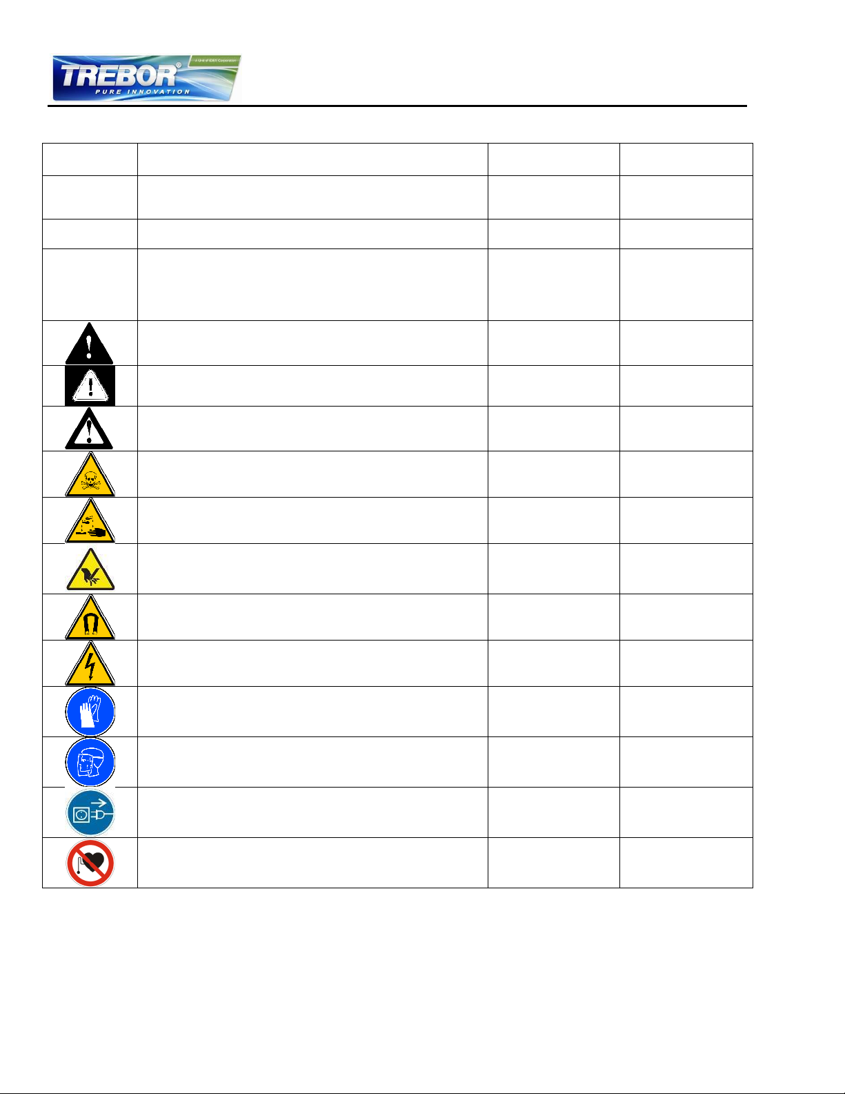
Symbol /
Signal Word
Description
Type
Source
DANGER
Indication of an imminently hazardous situation that, if not
avoided, will result in death or severe injury. Limited to the
most extreme situation
Signal word
SEMI S1-0701
WARNING
Indication of a potentially hazardous situation, which if not
avoided, could result in death or severe injury.
Signal word
SEMI S1-0701
CAUTION
Indication of potentially hazardous situations, which if not
avoided, could result in moderate or minor injury. Also, alert
against unsafe practice.
Without safety alert indication of hazardous situation which, if
not avoided, could result in property damage.
Signal word
SEMI S1-0701
Safety alert for “Warning” and “Caution”
Safety alert
SEMI S1-0701
Safety alert for “Danger”
Safety alert
SEMI S1-0701
Caution (refer to accompanying documents) (is used on
article labels for reference to manual)
Refer to manual
ISO 3864
Toxic material, poison
Hazard identification
IEC 61310
Corrosive material, corrosion
Hazard identification
IEC 61310
Cut/sever hand, sharp object
Hazard identification
ANSI Z535.3
Strong magnetic field
Hazard identification
SEMI S1-0701
Danger: electricity, electrical hazard
Hazard identification
IEC 61310, ISO 3864
Wear safety gloves
Hazard avoidance
Mandatory action
IEC 61310
Wear face shield
Hazard avoidance
Mandatory action
SEMI S1-0701
Unplug power line
Hazard avoidance
Mandatory action
SEMI S1-0701
No pacemakers
Hazard avoidance
Prohibition
SEMI S1-0701
9.2 Symbols and Signal Words
REV6 OPERATION / MAINTENANCE MANUAL 34 CONTENTS
 Loading...