

Page 1
Phone: 800-669-1303 or 801-561-0303
Fax: 801-255-2312
e-mail: [email protected]
PURUS 20
Operation / Maintenance
Manual
SERIAL NUMBER (located on back of product):
PATENTS: U.S. 7.134.849, 7.021.062 06/10/13 – MP20
Page 2

CONTENTS
1 INTRODUCTION .......................................................................................................... 3
2 INSTALLATION ............................................................................................................ 4
2.1 UNPACKING ...................................................................................................... 4
2.2 UTILITIES / HOOK-UP ....................................................................................... 4
3 TEMPERATURE AND PRESSURE LIMITS ................................................................ 6
3.1 HIGH TEMPERATURE OPERATION ................................................................ 6
3.2 HIGH BACK PRESSURE OPERATION ............................................................. 6
4 OPTIONS ...................................................................................................................... 7
4.1 FLUID PORT CONNECTION OPTIONS ............................................................ 7
4.2 HOOK-UP WITH SURGE SUPPRESSOR ......................................................... 7
5 START-UP .................................................................................................................... 8
5.1 PERFORMANCE CHARTS ................................................................................ 8
6 INSPECTION AND MAINTENANCE ......................................................................... 10
6.1 MAINTENANCE ............................................................................................... 10
6.2 PART REFERENCE ILLUSTRATION – P20 ................................................... 10
6.3 PART REFERENCE LIST – P20 ...................................................................... 10
7 TROUBLESHOOTING ............................................................................................... 11
8 WARRANTY ....................................................................................................... 12
P20 PUMP OPERATION / MAINTENANCE MANUAL CONTENTS
Page 3
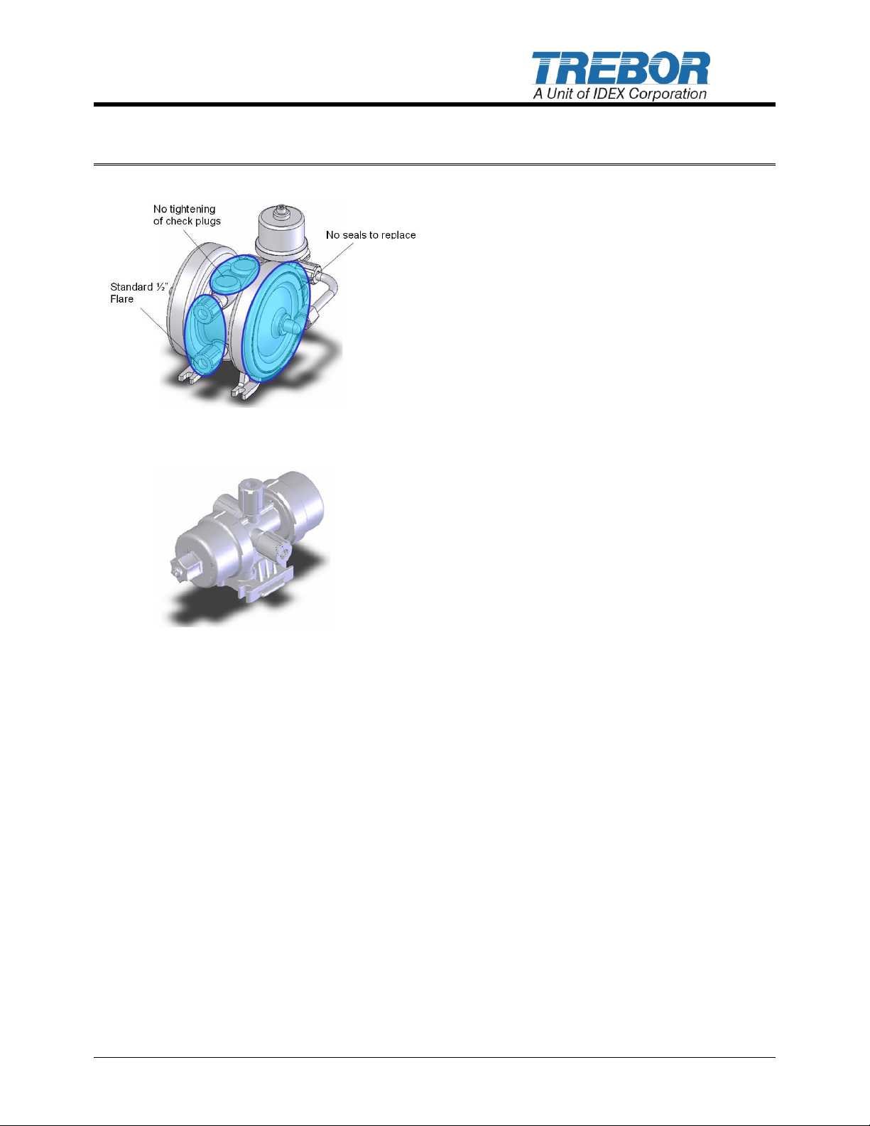
Figure 1-1: Injection Molded & Welded
Design
Figure 1-2: Optional PC7 Controller
1 INTRODUCTION
PFA injection molded high purity
disposable pump.
TREBOR’S Purus 20 diaphragm pump
addresses maintenance, rebuild, and cost
issues common in many chemical pumps by
using an injection molded PFA design with
minimal welded parts. This design (Figure 1-1)
creates a reliable, disposable pump that costs
less than many competitor pump rebuild kits.
The Purus 20 provides peace of mind because
of its purity, performance, and simplicity.
Purus pumps can be externally controlled or
installed as a self-contained unit using
TREBOR’S PC7 (Figure 1-2) air-powered
pump controller that mounts on the Purus 20,
as shown in (Figure 1-1).
Product Benefits
Operating life exceeding 100 million
cycles in many applications
Excellent suction lift and priming
capability
No elastomer seals or gaskets to replace
No metal parts to corrode or contaminate
process
Compact size
100% PFA/PTFE construction for the
chemical compatibility and process purity
FM4910 compliant
Cleaned, assembled, and packaged in
Class 1000 cleanroom
CE Certified
P20 PUMP OPERATION / MAINTENANCE MANUAL PAGE 3
Page 4
Qty
Item
Description
1
1
1
PURUS 20
MP20
PC7
Purus 20 Pump
Manual, Purus 20 pump
PC& Pump Controller (optional)
2 INSTALLATION
2.1 UNPACKING
After unpacking, the pump should be checked for any damage that may have occurred
during shipment. Damage should be reported to the carrier immediately.
NOTE: Although extensive efforts are made to deliver pumps to our customers completely
dry, new pumps may contain residual moisture from their final DI water test.
The following items should be included within the shipping container:
2.2 UTILITIES / HOOK-UP
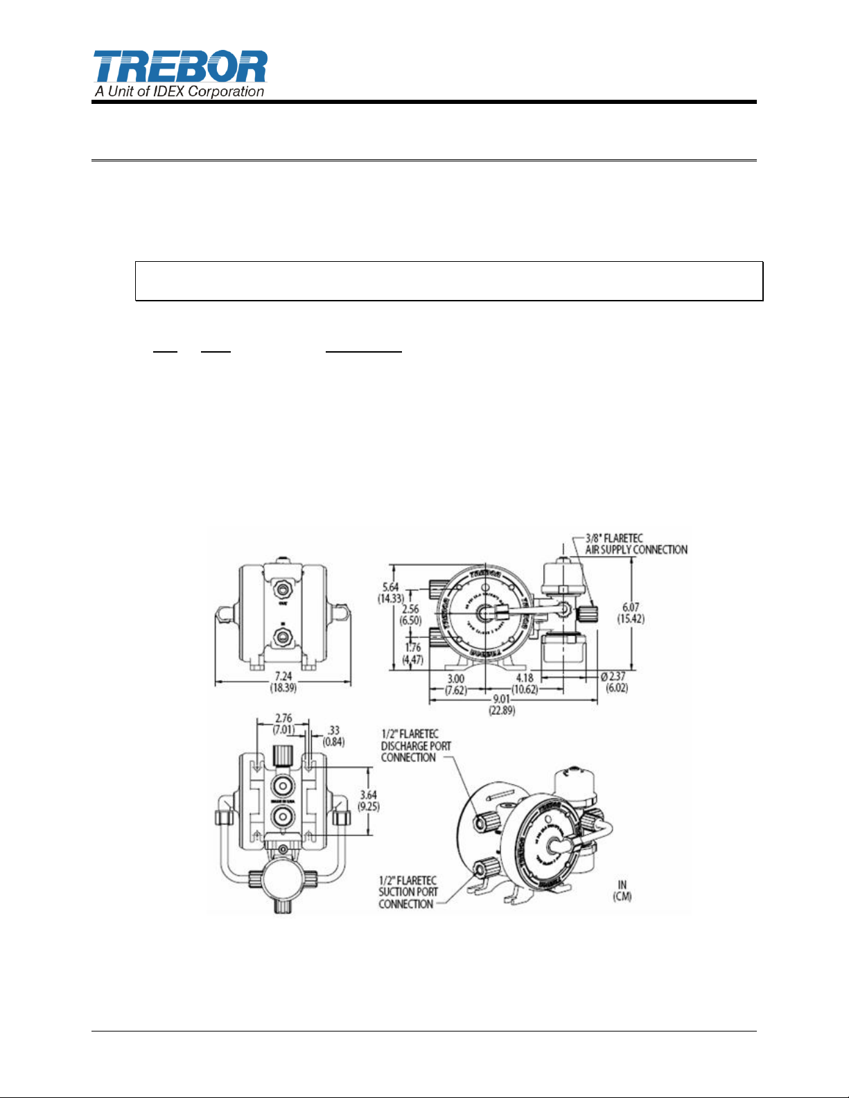
The pump is mounted using four ¼” (6mm) bolts. It is recommended that the pump be
positioned within 15° from level to maintain self-priming ability and pumping efficiency.
Allow sufficient room for tubing connectors.
Figure 2-1: Dimensions (with mounted PC7 option & flare connection)
PAGE 4 P20 PUMP OPERATION / MAINTENANCE MANUAL
Page 5

Air Inlet: 3/8” OD Tubing)
Air Supply: 20-80 PSIG (0.14 - 0.55 Mpa), clean dry air or inert gas
Fluid Ports: 1/2” Flaretek standard (other options available)
For maximum flow the following is recommended:
1. Maximize supply line diameter
2. Minimize supply line length
3. Minimize supply line restrictions (i.e. valves, fittings)
NOTE: It is recommended that a filter be placed on the discharge side of the pump.
ATTENTION: The pump should be operated with clean, dry air or nitrogen. Particulate,
water and oils in the air supply can damage the pump.
P20 PUMP OPERATION / MAINTENANCE MANUAL PAGE 5
Page 6
3 TEMPERATURE AND PRESSURE LIMITS
3.1 HIGH TEMPERATURE OPERATION
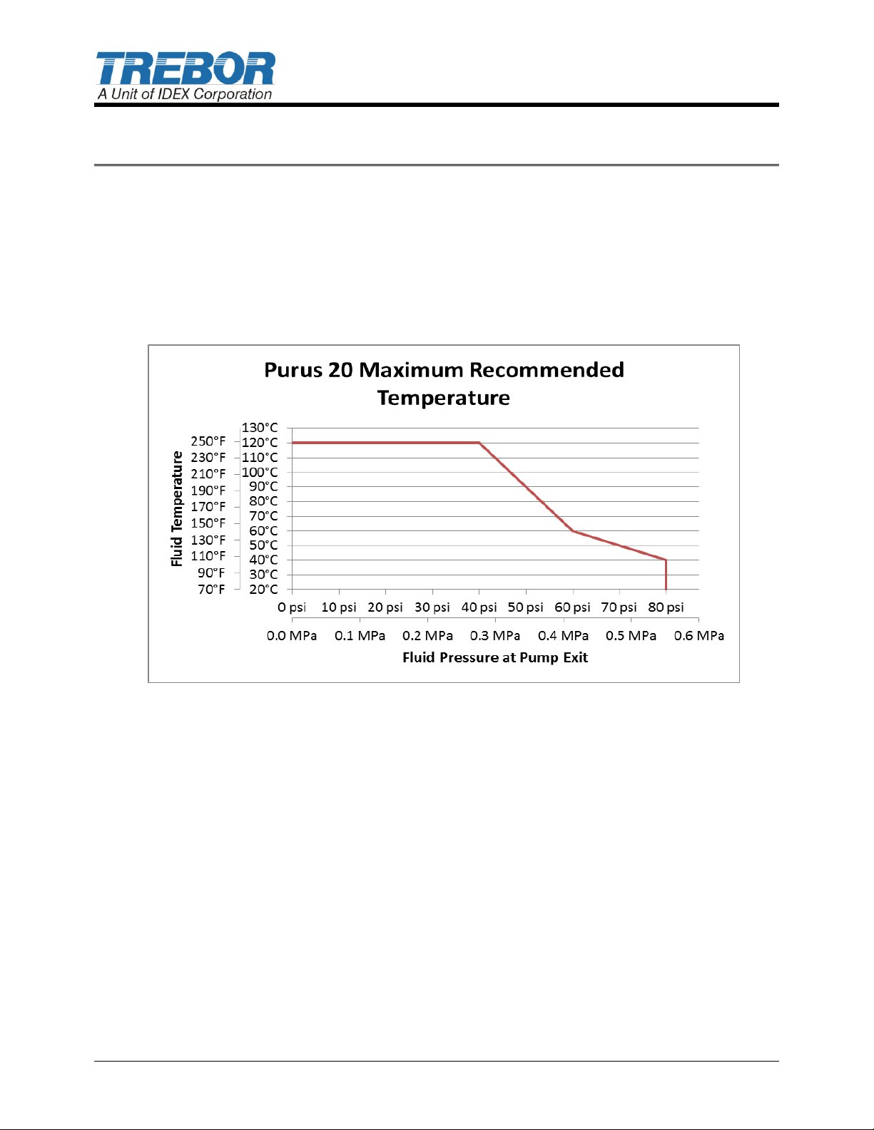
The Purus 20 pump is molded out of virgin PFA. This enables high temperature operation
under specific conditions. The maximum temperature will vary in relation to the supply
pressure. Figure 3-1 shows Trebor’s maximum recommended temperature for the pump.
Exceeding the temperature for a corresponding supply pressure could cause the pump to
develop leaks at the pump main seal between the air and fluid chambers.
Figure 3-1: Purus 20 Recommended Temperature Curve
3.2 HIGH BACK PRESSURE OPERATION
Increasing the fluid outlet pressure, or back pressure, causes stress on the pump main
seal. High back pressure, around 90% of the supply pressure, can cause the pump to
develop leaks at the main seal. It is not recommended to run the Purus 20 pump at near
dead head conditions.
High back pressure and elevated fluid temperatures can combine to increase the
likelihood of pump failure due to a main seal leak. Higher temperature reduces the yield
strength of PFA, while higher stresses are induced by the high back pressure. The
combination of those two operating conditions can cause the main seal to unload, which
can lead to a leak. Due to the potential variations in operating conditions, the typical range
of material properties and the tolerance stack up, it is impossible to identify the exact
points where main seal leaks become probable due to temperature/back pressure
interactions.
PAGE 6 P20 PUMP OPERATION / MAINTENANCE MANUAL
Page 7

4 OPTIONS
4.1 FLUID PORT CONNECTION OPTIONS
Additional options are available. Please contact Trebor Sales Department for details
regarding available options.
½” Flaretek (standard)
½” Pillar, Super 300 (optional)
4.2 HOOK-UP WITH SURGE SUPPRESSOR
For surge suppression, Trebor International recommends the use of the SS40 inline surge
suppressor. Consult factory for installation and performance specifications. Information
also available at www.treborintl.com
NOTE: See Surge Suppressor Operation Manual for detailed installation instructions.
P20 PUMP OPERATION / MAINTENANCE MANUAL PAGE 7
Page 8
Air Supply
Pressure
(PSIG)
Discharge
Fluid
Pressure
(PSIG)
Flow
(LPM)
Cycles
Per
Minute
Displacement
cc Per
Cycle
Air
Consumption
(CFM)
20 0 14
100
140
4.6
20
10
11
100
110
40 0 18.5
180
103
6.0
40
20
12.5
104
125
60 0 20
210
95
7.0
60
30
15
110
137
80 0 21
218
97
8.0
80
40
16
132
121
5 START-UP
Open the fluid suction (IN) line valve, if necessary
Open the fluid discharge (OUT) line valve, if necessary
Pump air supply pressure should be regulated
Operate pump at 20 psig initially to prime pump
Increase pressure to attain desired flow, (not to exceed 80 psig)
If the pump fails to start, refer to the troubleshooting section or contact Trebor for
further assistance.
ATTENTION: Prolonged periods (>5 minutes) of running without fluid can damage critical
internal pump parts.
CAUTION: When handling potentially dangerous fluids under pressure, the pump
and its fittings should be placed in an enclosure away from operators.
5.1 PERFORMANCE CHARTS
Pumping capacity is a function of air supply pressure and volume, suction head, suction
line restrictions, discharge head, discharge line restriction, and fluid specific gravity and
viscosity.
Table 5-1: Performance Chart
NOTE: Test information is based on specific conditions and limited sampling. Use for
general reference only. This information is preliminary and may be changed at a future
date.
PAGE 8 P20 PUMP OPERATION / MAINTENANCE MANUAL
Page 9
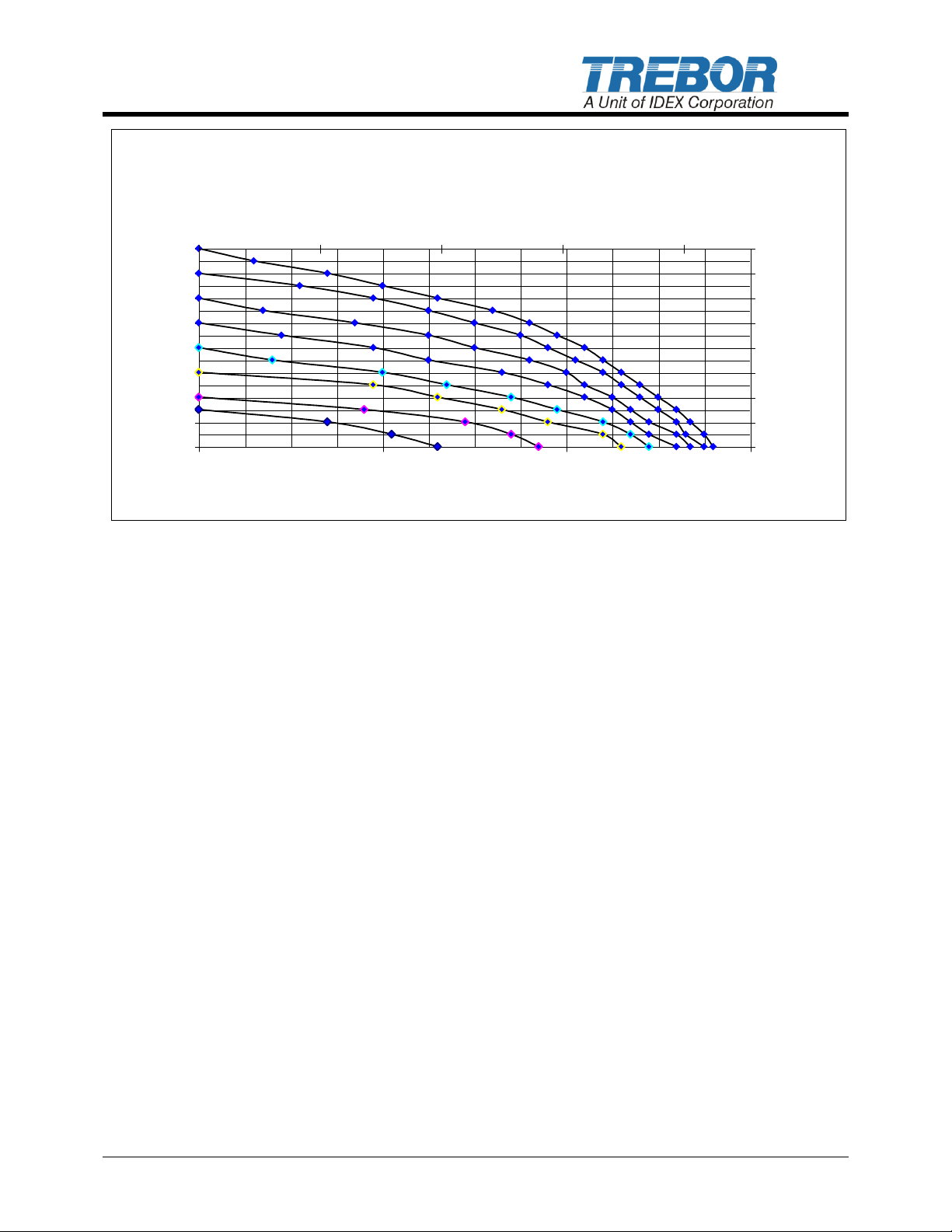
PURUS 20 w/PC7 CONTROLLER PERFORMANCE CURVES
0
10
20
30
40
50
60
70
80
0 2 4 6
FLOW (GPM.)
DISCHARGE PRESSURE
(PSIG)
0.00
0.70
1.41
2.11
2.81
3.52
4.22
4.92
5.62
0 5 10 15 20
FLOW (LPM)
DISCHARGE PRESSURE
Figure 5-1: Pressure and Capacity chart
P20 PUMP OPERATION / MAINTENANCE MANUAL PAGE 9
Page 10
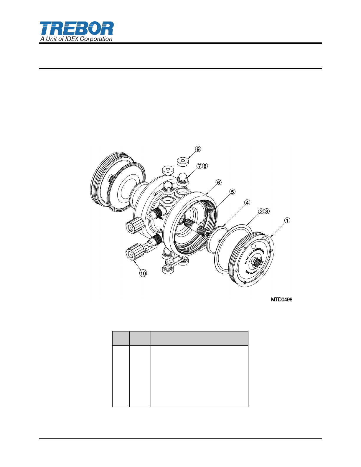
ILL
NO
QTY
DESCRIPTION
1 2 HEAD 2 2
DIAPHRAGM
3 2 MAIN SEAL
4 2 PUSH PLATE
5 1 SHAFT
6 1 BODY ASSY
7 2 SUCTION SEAT
8 4 CHECK BALL
9 4 CHECK CAP
10 2 1/2T FLR NUT
6 INSPECTION AND MAINTENANCE
6.1 MAINTENANCE
TREBOR’S PURUS 20 has no serviceable parts, due to its welded and sealed
construction. Please neutralize and dispose of the pump accordingly or contact the
factory regarding methods of recycling.
6.2 PART REFERENCE ILLUSTRATION – P20
Figure 6-1 Exploded View
6.3 PART REFERENCE LIST – P20
PAGE 10 P20 PUMP OPERATION / MAINTENANCE MANUAL
Page 11

Pump Will Not Start, Fails to Operate
Cause:
Solution:
Insufficient air pressure
Increase regulated supply pressure or check control
valves for proper operation.
Rotate PC7 speed control screw CW until it stops. Then
readjust for correct speed (if applicable).
Debris in shuttle valve
Inspect/clean control valve assembly.
PC7 (if applicable)
Refer to PC7 Manual
Bubbles in Fluid Discharge
Cause:
Solution:
Inlet line fittings not tight
Check and tighten all fittings on the suction line feeding
the pump.
Flow too high
Under high flow conditions some fluids can cavitate
releasing dissolved air bubbles.
Diaphragm failure due to puncture
Contact Trebor Customer service for additional service
recommendations. Replace pump.
Fluid Leaks
Cause:
Solution:
Weld failure of fluid pump
Replace pump (Non Serviceable)
Fluid leaking from suction or discharge
connections
Inspect tubing and tighten fluid fittings.
Erratic Cycling
Cause:
Solution:
Debris in shuttle valve
Inspect/clean control valve assembly.
PC7 (if applicable)
Refer to PC7 Manual
7 TROUBLESHOOTING
P20 PUMP OPERATION / MAINTENANCE MANUAL PAGE 11
Page 12

8 WARRANTY
See the Trebor Standard Limited Warranty at:
http://www.treborintl.com/TechnicalSupport.aspx
PAGE 12 P20 PUMP OPERATION / MAINTENANCE MANUAL
 Loading...