

Page 1
Phone: 800-669-1303 or 801-561-0303
Fax: 801-255-2312
E-mail: [email protected]
www.treborintl.com
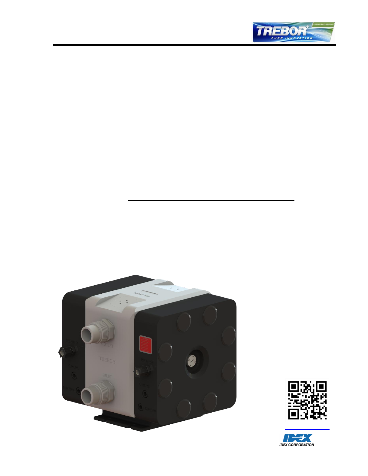
MEGA 120E PUMP
Operation / Maintenance Manual
SERIAL NUMBER (located on top of product):
PATENTS: U.S. 09642426, U.S. 06106246, U.S. 05971402, U.S. 05370507 1/17/14 – M120E-A
Page 2

CONTENTS
1 INSTALLATION ............................................................................................................ 3
1.1 UNPACKING ...................................................................................................... 3
1.2 TIE BOLT TORQUE ........................................................................................... 3
1.3 UTILITIES / HOOK-UP ....................................................................................... 3
2 OPTIONS ...................................................................................................................... 6
2.1 FLUID PORT CONNECTION OPTIONS ............................................................ 6
2.2 FLUID FITTINGS / SURGE SUPPRESSOR HOOK-UP .................................... 6
2.3 OPTIONAL LEAK SENSING .............................................................................. 7
2.3.a Installation .............................................................................................. 7
2.3.b Removal ................................................................................................. 7
2.3.c Sensor Signal Specifications ................................................................. 7
3 START-UP .................................................................................................................... 9
3.1 HIGH TEMPERATURE OPERATION ................................................................ 9
3.2 PERFORMANCE CHARTS ................................................................................ 9
4 MAINTENANCE .......................................................................................................... 11
4.1 PREVENTIVE MAINTENANCE SCHEDULE ................................................... 11
4.1.a Preventive Maintenance Record ......................................................... 13
4.2 RECOMMENDED SPARE PARTS .................................................................. 14
4.3 TOOLS .............................................................................................................. 14
4.4 PARTS ILLUSTRATION ................................................................................... 15
4.5 PARTS LIST ..................................................................................................... 16
4.6 CLEAN-UP ........................................................................................................ 16
4.7 DISASSEMBLY ................................................................................................ 16
4.7.a Quick Exhaust/Muffler Disassembly .................................................... 17
4.7.b Body Disassembly ............................................................................... 17
4.8 ASSEMBLY ...................................................................................................... 17
4.8.a Quick Exhaust (Both Heads) ............................................................... 17
4.8.b Body Assembly .................................................................................... 18
4.8.c Final Assembly .................................................................................... 21
4.9 TESTING .......................................................................................................... 22
4.9.a Performance Test ................................................................................ 22
4.9.b Dry Pump ............................................................................................. 22
4.9.c Dry Suction .......................................................................................... 22
5 TROUBLESHOOTING ................................................................................................ 23
6 WARRANTY AND EXCLUSIONS .............................................................................. 24
6.1 TREBOR STANDARD LIMITED WARRANTY ................................................. 24
7 CONTACT INFORMATION ........................................................................................ 25
7.1 GENERAL CONTACT INFORMATION ............................................................ 25
7.2 TECHNICAL SUPPORT ................................................................................... 25
7.3 REGIONAL REPRESENTATIVES ................................................................... 25
MEGA 120E PUMP OPERATION / MAINTENANCE MANUAL CONTENTS
Page 3

Qty
Item
Description
1
120E
Mega 120E Pump
1
M120E
Operation/Maintenance Manual
1 INSTALLATION
1.1 UNPACKING
After unpacking, the pump should be checked for any damage that may have occurred
during shipment. Damage should be reported to the carrier immediately.
The following items should be included within the shipping container:
1.2 TIE BOLT TORQUE
The tie bolts on the pump are tightened before leaving the factory. However, relaxation
may occur due to handling, material creep, or other unforeseen events. Trebor
recommends that all eight tie bolts be re-tightened upon pump install. The following
procedure should be used:
1. Remove black tie bolt caps (Item 17 in Figure 4-1) from both sides of all 8 tie
bolts6
2. Apply 80 in-lbs. (9.0 N-m) of torque to each slave side bolt while holding the
master side bolt stationary. A star-pattern is advised.
a. The master side is the left side of the pump if you are looking at the fluid
ports.
3. Replace the tie bolt caps.
1.3 UTILITIES / HOOK-UP
The pump is mounted using four 1/4” bolts. It is recommended that the pump be
mounted not more than 15 from level to maintain its self-priming ability and pumping
efficiency.
Air Inlet: 3/8” FNPT (3/8” Dia. [8mm] supply tube minimum).
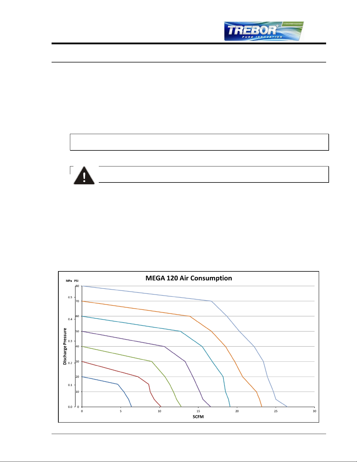
Air Supply: 25-80 psig (0.17-0.55 MPa) clean dry air or nitrogen. (For Air
Consumption, See 3.2 Performance Charts)
Fluid Ports: Inlet/Outlet Fluid Fittings and Surge Suppressor require tightening to
specified torque values during pump installation. See section 2.2 for
installation diagram and torque values.
Remote
Exhaust: 3/8” FNPT (3/8” Dia. minimum tube up to 6’ length, 1/2” Dia. Minimum
tube greater than 6’ length).
MEGA 120E PUMP OPERATION / MAINTENANCE MANUAL PAGE 3
Page 4
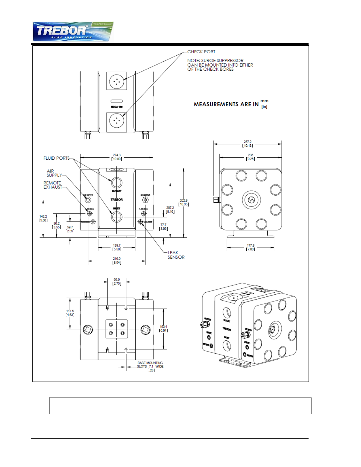
Figure 1-1
ATTENTION: The pump should be operated with clean, dry air or nitrogen. Particulate,
water and oils in the air supply can damage the pump.
PAGE 4 MEGA 120E PUMP OPERATION / MAINTENANCE MANUAL
Page 5

NOTE:
1. It is recommended that a filter be placed on the discharge side of the pump.
2. Although extensive efforts are made to deliver pumps to our customers completely
dry, new pumps may contain residual moisture from their final DI water test.
Recommended Maximum Operating Levels:
Maximum supply CDA/N2 pressure: 80 psig (0.55 MPa)
Maximum fluid temperature: 212°F (100°C)
MEGA 120E PUMP OPERATION / MAINTENANCE MANUAL PAGE 5
Page 6
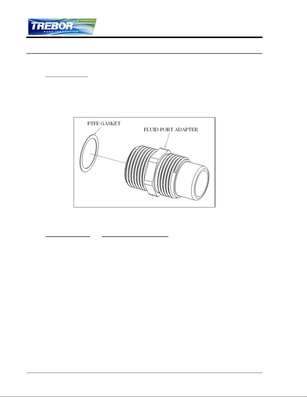
Surge Suppressor
Assembled Height: mm (in)
SS85
434.9 (17.12)
SS95
382.5 (15.06)
Figure 2-1
2 OPTIONS
2.1 FLUID PORT CONNECTION OPTIONS
Available Options
A. Flare style tube adapter 1 1/4” tube fitting – made of high purity PFA
PVDF flare nuts (standard)
PFA flare nuts (optional)
B. Custom fittings Contact Trebor Representative
2.2 FLUID FITTINGS / SURGE SUPPRESSOR HOOK-UP
PAGE 6 MEGA 120E PUMP OPERATION / MAINTENANCE MANUAL
Page 7
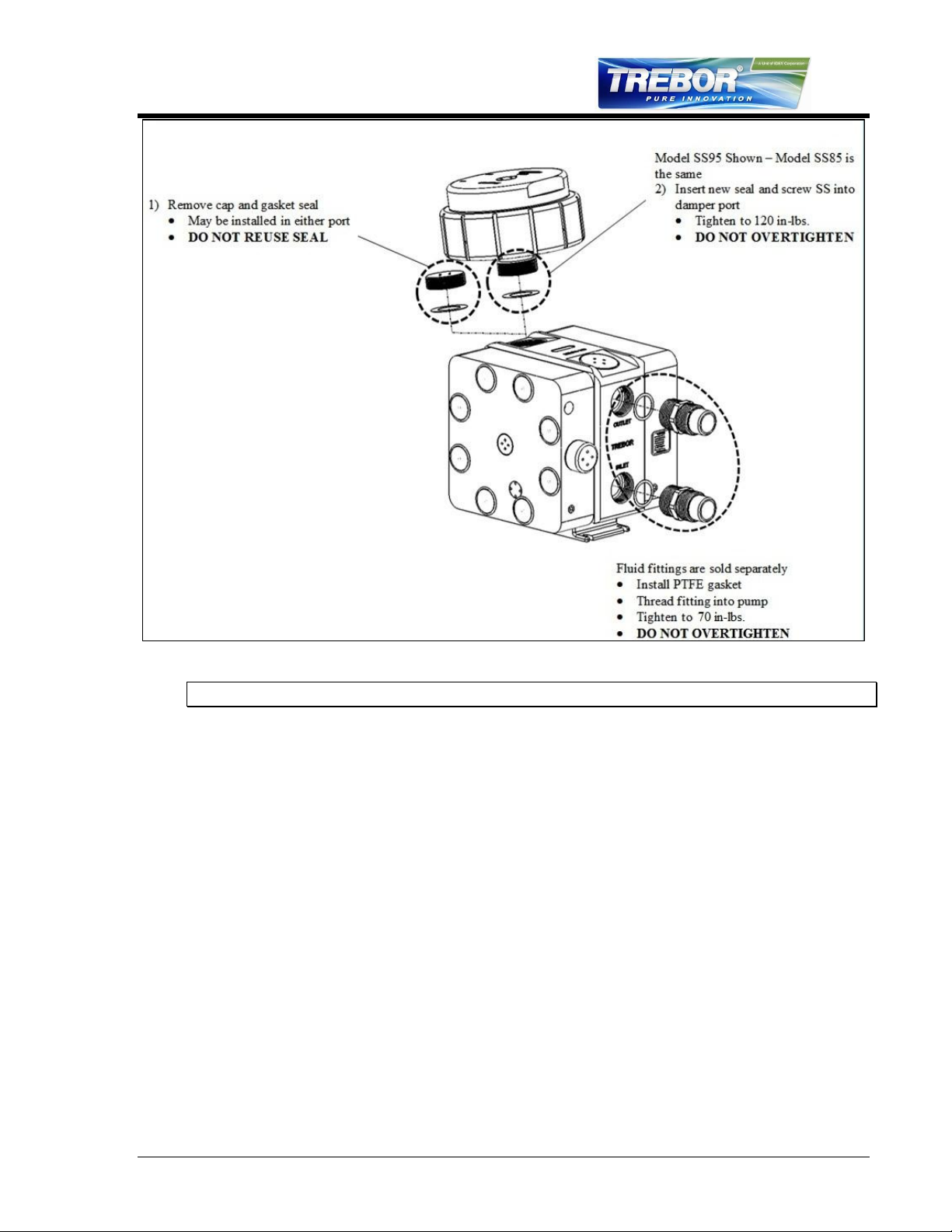
Figure 2-2
NOTE: See Surge Suppressor Operation Manual for detailed installation instructions.
2.3 OPTIONAL LEAK SENSING
2.3.a Installation
Remove 3/8 NPT plug from port.
Install 3/8 NPT leak probe fitting into port. See Figure 2-3 for illustration.
Install probe assembly into fitting. Probe is self-sealing and does not require
a seal.
Tighten nut hand-tight.
Connect fiber optic cable to sensor (NOTE: Minimize bends in fiber optic
cable to 2” radius minimum to help ensure optimum signal strength.). Fiber
optic cable can be cut to desired length using the cable cutter provided.
2.3.b Removal
Remove nut from fitting.
Remove probe.
2.3.c Sensor Signal Specifications
The sensor signal is normally closed. In the event of a leak, no light signal is
returned to the sensor.
MEGA 120E PUMP OPERATION / MAINTENANCE MANUAL PAGE 7
Page 8
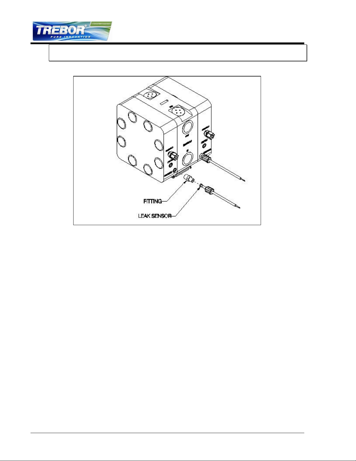
NOTE: See your fiber optic sensor installation instructions for proper hook-up and
adjustment.
Figure 2-3
PAGE 8 MEGA 120E PUMP OPERATION / MAINTENANCE MANUAL
Page 9
3 START-UP
Pump air supply pressure should be regulated.
Open the fluid suction (IN) line valve, if necessary.
Open the fluid discharge (OUT) line valve, if necessary.
Start with air regulator at low pressure setting (<15 psig). Increase or
decrease air pressure to attain desired flow, up to 80 psig (0.55 MPa).
Refer to Troubleshooting, Section 5, if pump fails to start.
ATTENTION: Prolonged periods of dry running (>5 minutes) will damage critical internal
pump parts.
CAUTION: When handling potentially dangerous fluids under pressure, the
pump and its fittings should be placed in an enclosure.
3.1 HIGH TEMPERATURE OPERATION
Pump operation at temperatures above 60°C requires periodic tightening of the tie bolt
nuts. The frequency of this procedure is best established by the user.
3.2 PERFORMANCE CHARTS
Pumping capacity is a function of air supply pressure and volume, suction head, suction
line restrictions, discharge head, discharge line restriction, and fluid properties. The
following data was taken using water at atmospheric temperature and pressure with
limited sample sizes. The data is intended to aid in system design and should be used
for general reference only.
Figure 3-1
MEGA 120E PUMP OPERATION / MAINTENANCE MANUAL PAGE 9
Page 10
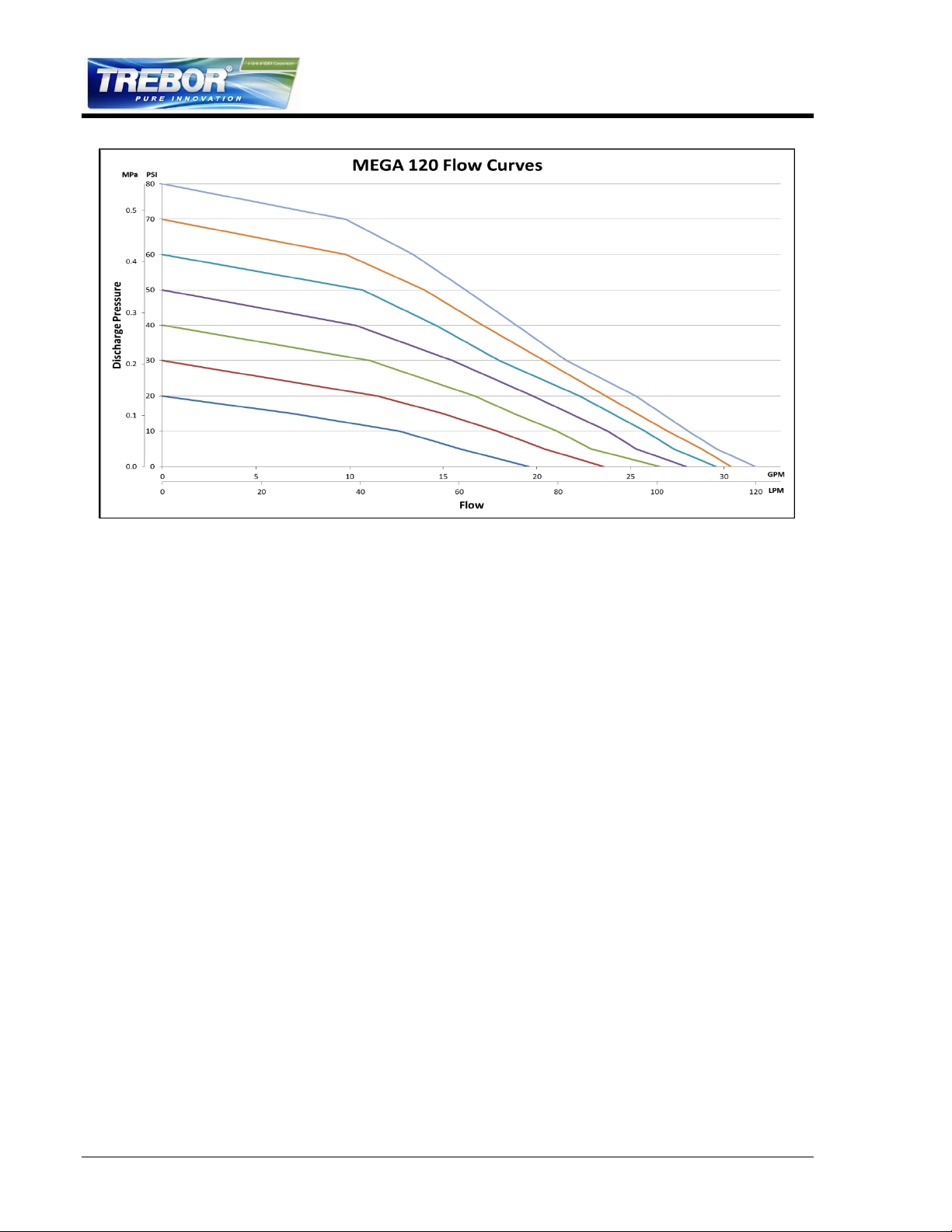
Figure 3-2
PAGE 10 MEGA 120E PUMP OPERATION / MAINTENANCE MANUAL
Page 11
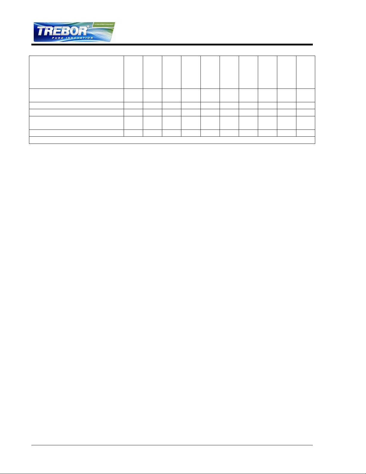
MEGA 120E Maintenance Schedule
Install
30 Days
3 Months
6 Months
9 Months
12 Months
15 Months
18 Months
21 Months
24 Months
Tie Bolt Torque (80 in-lb.)
I I I I
I
Check Seat Wear Rings
R
Shaft Bushing
R
Shaft (High Suction Applications)
R
Shaft
R
Diaphragms and Main Seal
R
Diaphragms and Main Seal (HF)
R
4 MAINTENANCE
Trebor pump maintenance can be divided into two categories: air system maintenance
and fluid system maintenance. The purpose of air system maintenance is to prevent air
system failures such as stalling or erratic cycling. The purpose of fluid system
maintenance is to maintain suction and lift capabilities.
Pump Rebuild Service
Trebor International provides a factory rebuild service for customers using Trebor
products. Trebor will rebuild any standard pump (exclusive of options). Please contact
Trebor International Sales Department for current pricing. The fixed rebuild price
includes a factory rebuild and parts equivalent to the standard rebuild kit. Each factory
rebuild comes with a new one-year warranty. Repairs requiring more extensive part
replacements will be quoted prior to proceeding with the pump rebuild. If the pump has
exceeded its useful life and cannot be rebuilt, the customer may elect to purchase a new
Trebor pump. If the customer chooses not to rebuild or replace the pump, a $150.00
evaluation charge will be required.
All returned pumps are to be shipped freight prepaid with a valid Purchase Order for the
cost of rebuild service. Please contact Trebor International prior to returning your pump
to obtain an RMA Number and Pump Return Data Sheet to ensure proper safety
precautions. Each pump will be evaluated and repaired within 5 working days of the
receipt of pump at Trebor facility.
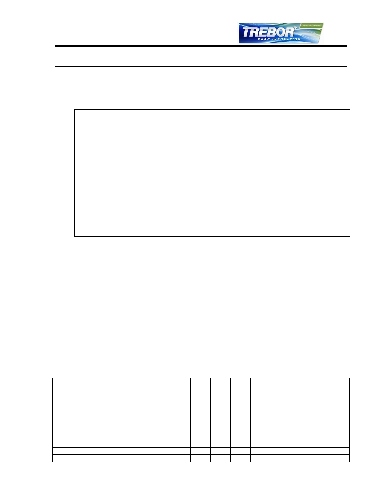
4.1 PREVENTIVE MAINTENANCE SCHEDULE
The following maintenance schedule is recommended to optimize pump performance
and minimize failures. Tie bolt torque should be checked within 30 days of start-up and
at periodic intervals thereafter. If the pump is subjected to thermal cycle operation, the
tie bolt torque should be checked after the first 3 thermal cycles and periodically
thereafter. Certain operating conditions that require more frequent maintenance
intervals have been noted. In positive pressure inlet conditions where suction or lift is
not required, fluid system maintenance may be extended. However, tie bolt retorque is
still recommended.
Adhering to the recommended preventative maintenance schedule along with periodic
inspection of the pump will ensure continued efficient operation and overall reliable
pump performance.
It is recommended that the Preventive Maintenance Record (Section 4.1.a) be copied,
maintained, and kept with this unit for future reference.
MEGA 120E PUMP OPERATION / MAINTENANCE MANUAL PAGE 11
Page 12
MEGA 120E Maintenance Schedule
Install
30 Days
3 Months
6 Months
9 Months
12 Months
15 Months
18 Months
21 Months
24 Months
Diaphragms and Main Seal (ACT 935 &
TMAH)
R
Quick Exhaust Seal
R
Check Balls and O-Rings
R
Check Balls and O-Rings
(High Suction Applications)
R
Exhaust Muffler Media
R
I=Inspect, R=Replace
PAGE 12 MEGA 120E PUMP OPERATION / MAINTENANCE MANUAL
Page 13

Company Name:
_____________________________________________________
Company Address:
_____________________________________________________
_____________________________________________________
Product:
_________________
Serial Number:
________________
Date:
________
Tech:
_____
Notes:
________________________________________
________________________________________
Date:
________
Tech:
_____
Notes:
________________________________________
________________________________________
Date:
________
Tech:
_____
Notes:
________________________________________
________________________________________
Date:
________
Tech:
_____
Notes:
________________________________________
________________________________________
Date:
________
Tech:
_____
Notes:
________________________________________
________________________________________
Date:
________
Tech:
_____
Notes:
________________________________________
________________________________________
Date:
________
Tech:
_____
Notes:
________________________________________
________________________________________
Date:
________
Tech:
_____
Notes:
________________________________________
________________________________________
Date:
________
Tech:
_____
Notes:
________________________________________
________________________________________
Date:
________
Tech:
_____
Notes:
________________________________________
________________________________________
Date:
________
Tech:
_____
Notes:
________________________________________
________________________________________
Date:
________
Tech:
_____
Notes:
________________________________________
________________________________________
Date:
________
Tech:
_____
Notes:
________________________________________
________________________________________
Date:
________
Tech:
_____
Notes:
________________________________________
________________________________________
Date:
________
Tech:
_____
Notes:
________________________________________
________________________________________
Date:
________
Tech:
_____
Notes:
________________________________________
________________________________________
Date:
________
Tech:
_____
Notes:
________________________________________
________________________________________
Date:
________
Tech:
_____
Notes:
________________________________________
________________________________________
Date:
________
Tech:
_____
Notes:
________________________________________
________________________________________
Date:
________
Tech:
_____
Notes:
________________________________________
________________________________________
Date:
________
Tech:
_____
Notes:
________________________________________
________________________________________
Date:
________
Tech:
_____
Notes:
________________________________________
________________________________________
Date:
________
Tech:
_____
Notes:
________________________________________
________________________________________
Date:
________
Tech:
_____
Notes:
________________________________________
________________________________________
4.1.a Preventive Maintenance Record
MEGA 120E PUMP OPERATION / MAINTENANCE MANUAL PAGE 13
Page 14

KR120E-00-A Spares Rebuild Kit, which includes:
Part No
Qty
Description
KD120-00-A
1
Diaphragm Kit
Includes:
(2)
(2)
1900B0023
98001585
Diaphragm Set
FKM O-Ring
KM120E-00-A
1
Maintenance Kit
Includes:
(2)
(2)
(2)
(2)
(2)
1900B0016
98003047
L0119
BL002
BL007
Quick Exhaust Port
Quick Exhaust Seal
Muffler Assembly
Suction Seat
Check Port Gasket
98001108
4
Blue Caps
98004258
4
PTFE O-ring
98004255
4
PTFE Check Ball
L0100
16
Tie Bolt Cap
BL002
2
Suction Seat
BL007
2
Check Port Gasket
BL009
2
Fluid Port Gasket
BL012
1
Shaft Bushing
L0100
16
Tie Bolt Cap
KT120-00-A Tool Kit, which includes:
Part No
Qty
Description
98001230
1
5/32” Allen Wrench
98002136
2
7/16” Nut Driver
98002859
1
7/16” Socket
98003150
1
Tool Case
98003305
1
Drive Handle
T0172
1
Check Sleeve Insertion Tool
T0173
1
Check Sleeve Removal Tool
T0146
1
¾” Pin Tool
T0147
1
1” Pin Tool
T0148
1
½” Pin Tool
T0159
1
2” Pin Tool
T0144
1
Cleaning Tool
T000A0021
1
Shaft Bullet
4.2 RECOMMENDED SPARE PARTS
Kits are available with FFKM o-ring in place of FKM o-rings. Contact your Trebor
representative for more information.
In critical applications, a spare pump is recommended to minimize potential down time.
4.3 TOOLS
The following tool kit is recommended as standard service equipment.
PAGE 14 MEGA 120E PUMP OPERATION / MAINTENANCE MANUAL
Page 15
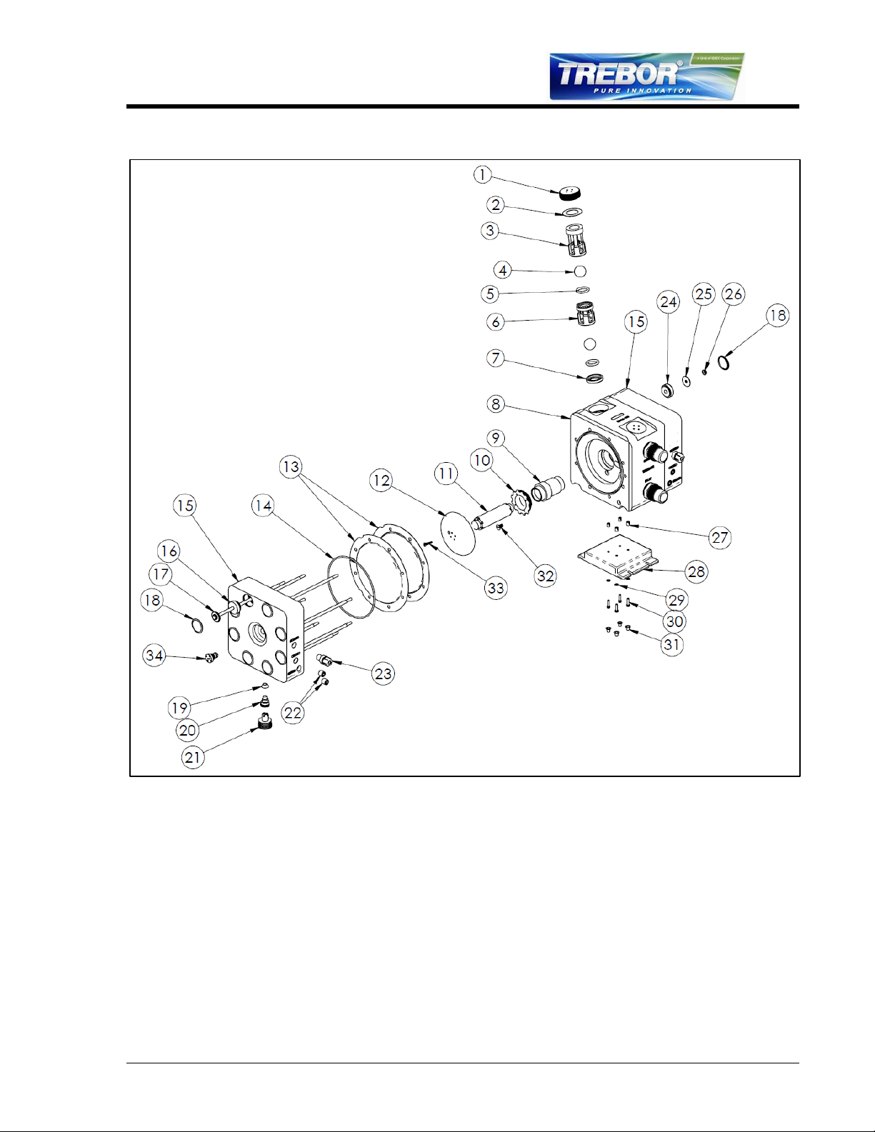
4.4 PARTS ILLUSTRATION
Figure 4-1
MEGA 120E PUMP OPERATION / MAINTENANCE MANUAL PAGE 15
Page 16
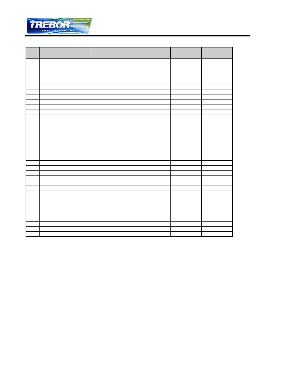
4.5 PARTS LIST
ILL
NO
PART NO
QTY
DESCRIPTION
PM
YEAR #
MATERIAL
1
BL006
2
Check Bore Plug
PTFE
2
BL007
2
Gasket Seal, Check Port
1
PTFE
3
BL004
2
Discharge Sleeve
PTFE
4
98004255
4
Check Ball
1
PTFE
5
98004258
4
O-Ring 1 PTFE
6
BL003
2
Suction Sleeve
PTFE
7
BL002
2
Suction Seat
PTFE
8
BL001
1
Body PTFE
9
BL012
1
Shaft Bushing
1
PTFE
10
L0195
1
Locking Ring
PTFE
11
BL011
1
Main Shaft
2
PFA
12
1900B0070
2
Push Plate
PTFE
13
1900B0023
2
Diaphragm Set
1
PFA
14
98001585
2
Main Seal
1
Viton
15
L0185-01
2
Head PP
16
L0184
8
Spacer, Tie Bolt
PP
17
BL014
8
Tie Bolt Assembly
SS316, PFA
18
L0100
16
Tie Bolt Cap
1
LDPE
19
98003047
2
Quick Exhaust Seal
1
Viton
20
1900B0016
2
Quick Exhaust Port
UHMW
21
L0119
2
Assembly, Muffler
1
PP
22
98002243
10
Plug, 3/8 NPT
PE
23
98003514
2
Fitting, Air
PP
24
L0140
8
Bushing
NPRN &
EPDM
25
1900A0028-01
8
Tie Bolt Washer
SS316
26
98002341
8
Nut, Flange, SS, 1/4 - 20
SS18-8
27
98001418
4
Insert SS18-8
28
BL017
1
Pump Base
PP
29
98001093
4
Washer
SS18-8
30
98001375
4
Screw SS18-8
31
98001108
4
Cap, Blue
LDPE
32
98003755
1
Screw, Lock Ring
PTFE
33
98003769
2
Screw, Push Plate
PTFE
34
AW073
2
End-of-Stroke Port Plug
PTFE
4.6 CLEAN-UP
To help remove potentially dangerous chemicals, the pump can be flushed with DI water
or disassembled and thoroughly cleaned. Take all appropriate safety precautions
commensurate with the chemical risks of the fluid.
4.7 DISASSEMBLY
During the life of the pump it will be necessary to perform certain preventative
maintenance procedures to ensure its continued high performance. This section and the
next (4.8 Assembly) are provided for the user’s convenience in disassembly and reassembly in performing these procedures.
PAGE 16 MEGA 120E PUMP OPERATION / MAINTENANCE MANUAL
Thoroughly clean/flush the pump using DI water (Refer to Section 4.6).
Remove tie bolt caps from the slave head.
Remove nuts from the tie bolts (Slave Head side). Leave tie bolts in place.
Lay the pump on its side with slave side up.
Page 17

Lift off the slave head.
Remove the main seal and diaphragms.
Remove the o-rings from the shuttle transfer tube.
Remove the body assembly.
Remove the second set of diaphragms and main seal.
Remove the transfer tube and o-rings from the heads and body.
Remove the remaining tie bolt caps and tie bolts.
NOTE: All polypropylene and fluoroplastic parts, when disassembled, should be
thoroughly washed and be free from chemical residue for handling purposes.
4.7.a Quick Exhaust/Muffler Disassembly
Remove the muffler assembly from each head.
Remove quick exhaust ports from heads.
Remove quick exhaust seals.
4.7.b Body Disassembly
Remove check bore plugs using 3/4” pin tool and remove seals.
Remove sleeves, balls, o-rings and check seat. Do not use excessive force.
Unthread push plate locking screw and push plate from the one side of the
shaft.
Remove remaining shaft and push plate from body.
Unthread second locking screw and push plate from shaft.
Unthread shaft bushing locking screw from body.
Using 2” pin tool, insert pins in shaft bushing locking ring located in the
master head side of chamber and rotate CCW to remove bushing. Then
push out bushing from the slave head chamber side.
4.8 ASSEMBLY
Prior to beginning assembly, inspect all parts to ensure they are clean and dry. Wear
clean, protective gloves.
4.8.a Quick Exhaust (Both Heads)
Insert quick exhaust seal.
Insert quick exhaust port in each head as shown. Tighten to 20 in-lbs. Do not
over tighten.
MEGA 120E PUMP OPERATION / MAINTENANCE MANUAL PAGE 17
Page 18
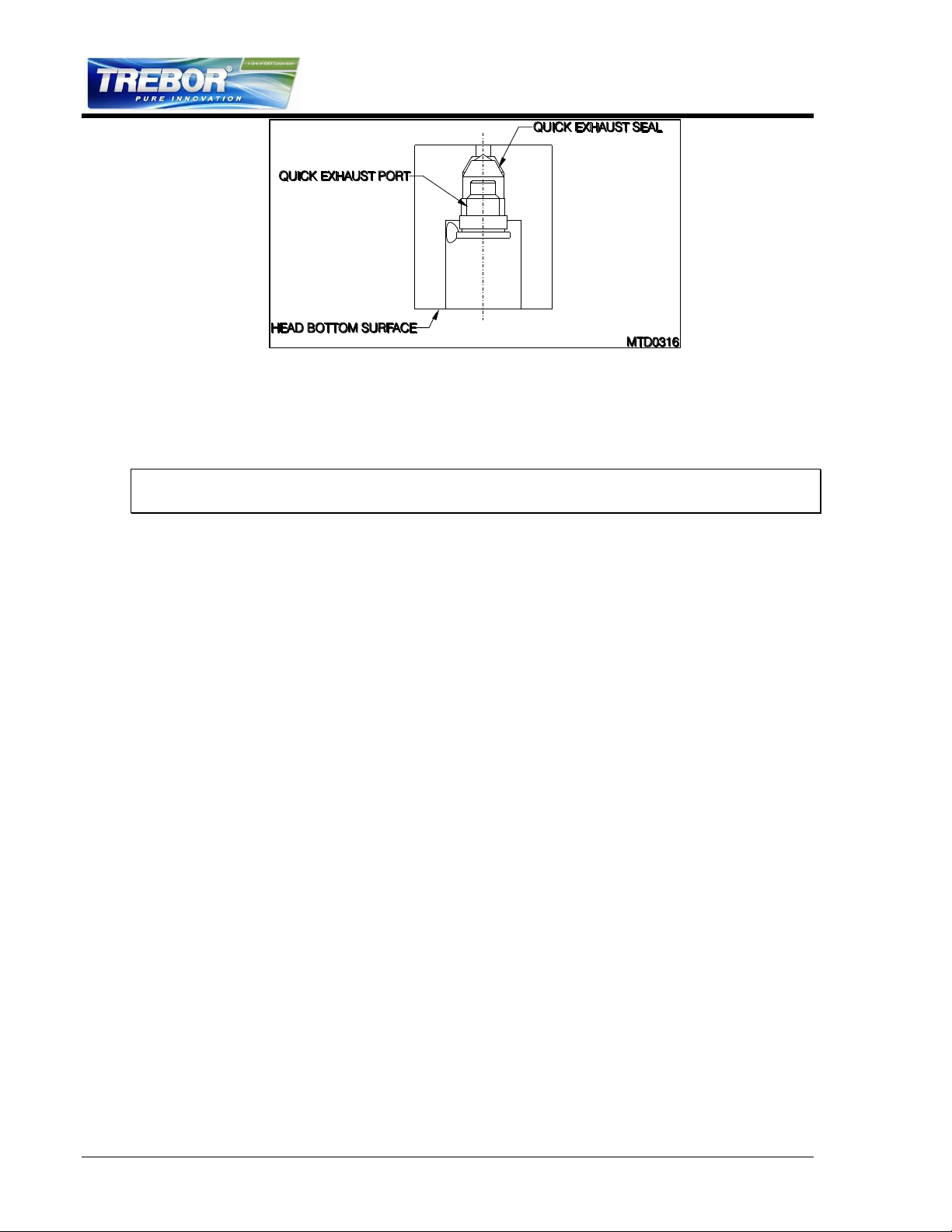
Figure 4-2
Install 3 each muffler pads onto muffler spool and insert into exhaust port.
Tighten to 40 0in-lbs.
4.8.b Body Assembly
NOTE: For easy installation, check sleeves that do not install easily (minimal effort) can
be placed in a freezer prior to assembly to assist insertion.
Insert the suction seat. Press firmly using the check sleeve insertion tool until the
suction seat is at the bottom of the check bore.
Install the o-ring. The o-ring should rest inside the cup shape in the seat.
Install the check ball. Ensure the o-ring does not become dislodged.
Insert the suction sleeve. Press firmly using the check sleeve insertion tool until the
suction sleeve meets the suction seat.
Install the o-ring. The o-ring should rest inside the cup shape in the seat.
Install the check ball. Ensure the o-ring does not become dislodged.
Install the discharge sleeve. The edge of the non-threaded part of the check bore
should be approximately flush with the top of the discharge sleeve.
See Figure 4-3 for the proper order of check assembly installation.
PAGE 18 MEGA 120E PUMP OPERATION / MAINTENANCE MANUAL
Page 19
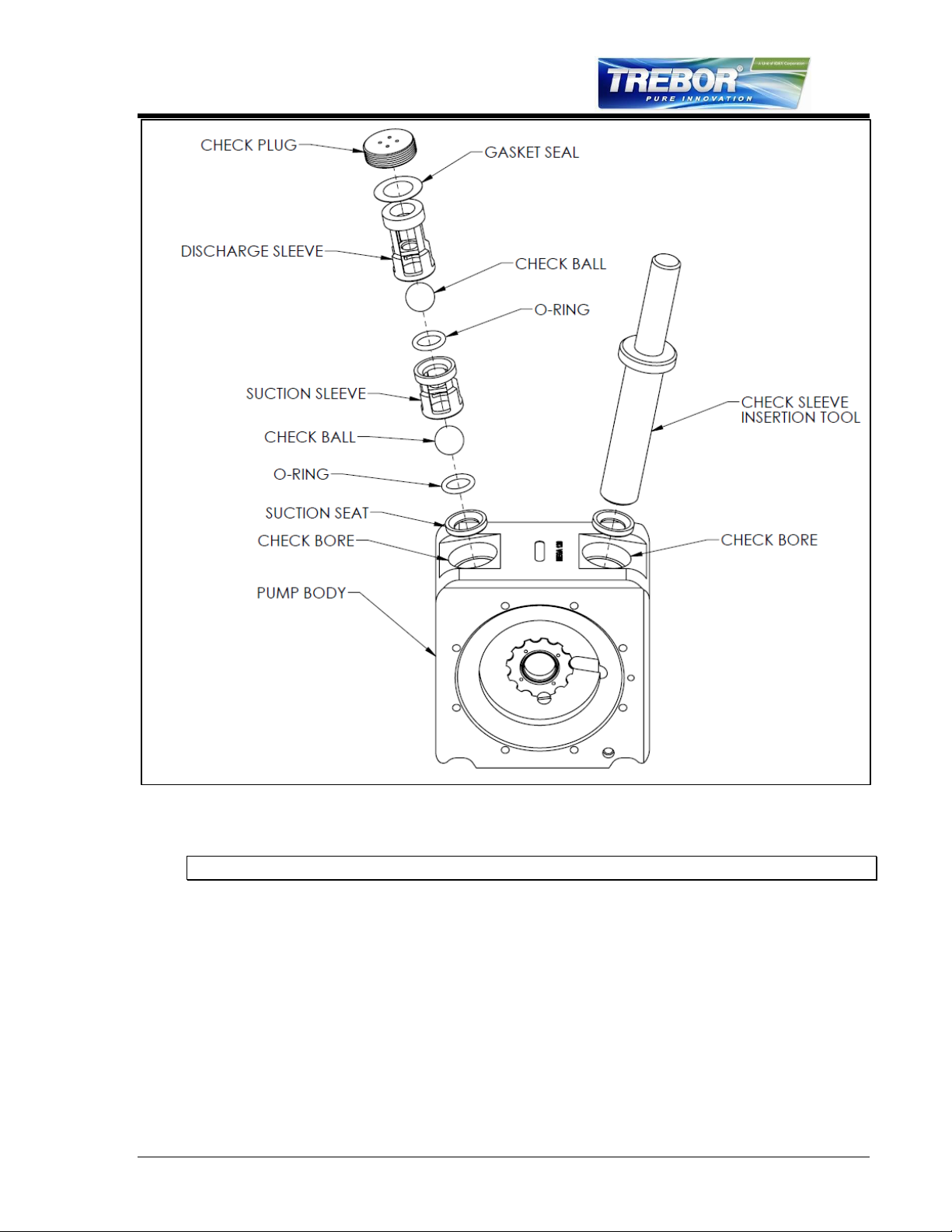
Figure 4-3
NOTE: The suction sleeves are shorter than the discharge sleeves.
Insert the gasket seal
Thread on the check port plug and tighten to 120 in-lbs.
Repeat process for second check bore.
MEGA 120E PUMP OPERATION / MAINTENANCE MANUAL PAGE 19
Page 20
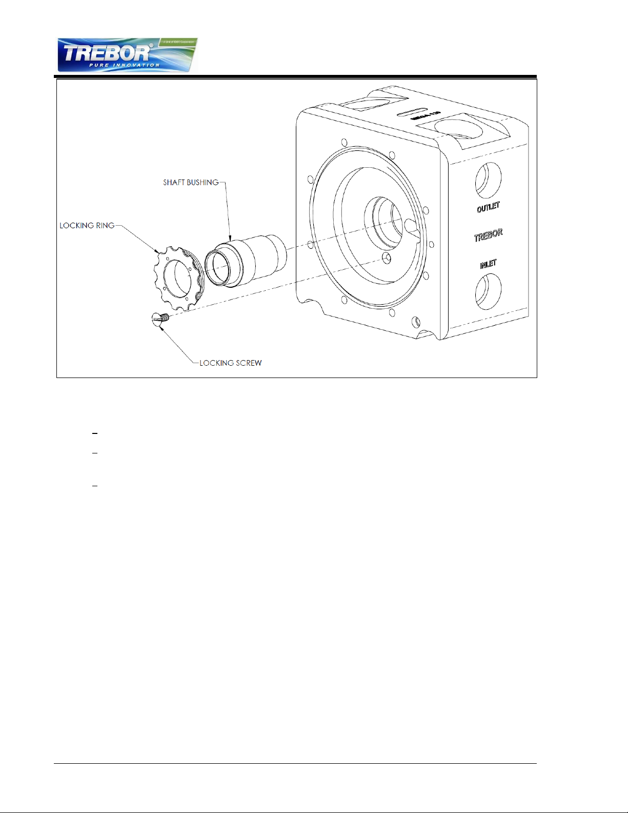
Figure 4-4
Install shaft bushing per Figure 4-4.
Install locking ring until flush with fluid cavity face and resistance is met.
Tighten until next available notch aligns with locking screw hole, check to assure that
the shaft bushing does not move.
Insert locking screw into hole and tighten until flush with locking ring.
Thread one push plate onto shaft until push plate bottoms out on shaft shoulder.
(See Figure 4-5.)
Tighten push plate to 48 oz.-in, and then rotate CW until locking screw hole is
aligned with the next available hole in shaft. The first push plate can be visually
aligned separate from the body.
Install push plate locking screw. Tighten to 12 oz.-in.
PAGE 20 MEGA 120E PUMP OPERATION / MAINTENANCE MANUAL
Page 21
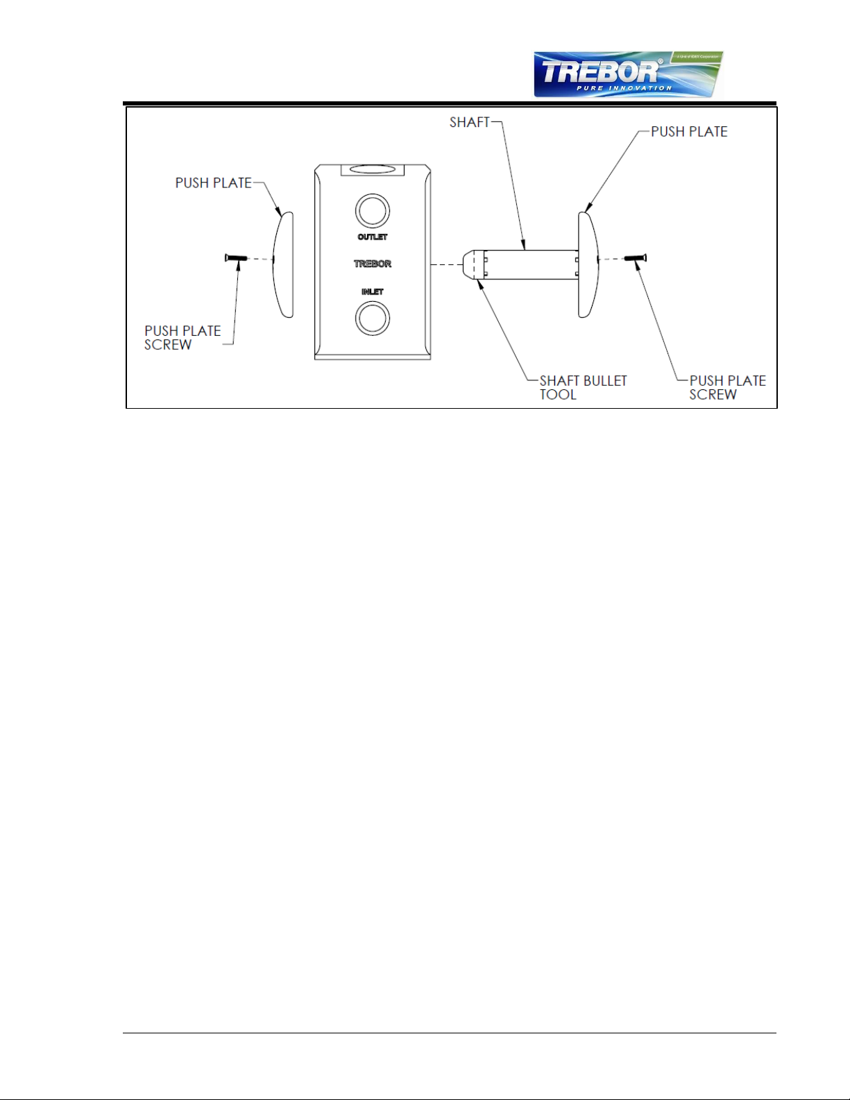
Figure 4-5
Insert shaft through shaft bore as shown in Figure 4-5. (Use shaft bullet tool to
prevent damage to shaft or shaft bushing.)
Thread on remaining push plate until push plate bottoms out on shaft shoulder.
The second push plate, while in the pump body, cannot be visually aligned. Tighten
push plate to 48 oz.-in, then insert alignment pin into locking screw hole. Rotate push
plate CW until locking screw hole is aligned with the next available hole in shaft and
alignment pin drops into the shaft hole. Remove alignment pin.
Install push plate locking screw. Tighten to 12 oz.-in.
4.8.c Final Assembly
(See Section 4.4, Parts Illustration, for reference.)
Insert tie bolts into head (press fit) and lay head flat with tie bolts sticking up.
Place main seal into the main seal groove in head.
Install two diaphragms, removing all air from between diaphragms, onto the
tie bolts and shuttle transfer tube. Note main seal groove alignment.
Place body assembly onto tie bolts and head.
Place remaining two diaphragms onto tie bolts. Note main seal groove
alignment.
Place the main seal O-ring into the formed groove of the diaphragms.
Flip the head over and insert the tie bolts into the second head. Ensure that
the main seal is not dislodged.
Place all bushings & flat washers onto tie bolt threaded ends.
Install flange nuts onto tie bolts. Tighten evenly in a star pattern (do not
overload one side before applying torque to another as dislodgment of main
seal can occur). Final torque is 80 in-lbs.
Snap in tie bolt caps.
MEGA 120E PUMP OPERATION / MAINTENANCE MANUAL PAGE 21
Page 22

4.9 TESTING
4.9.a Performance Test
Start with air regulator at low (< 15 psi) pressure setting.
Pump must prime once pressure is increased
60 psig Supply Pressure
Check for fluid leaks, listen for air leaks, check for irregularity
Prepare the pump for drying
4.9.b Dry Pump
Connect vacuum hose to discharge line
Connect purge line to fluid inlet
60 psig Supply Pressure
Cycle pump & vacuum dry by rotating pump side to side for 30 seconds.
Turn off Air Supply and allow the pump to purge for 5 minutes.
4.9.c Dry Suction
20 psig Supply Pressure Target
Record Suction Value
Target = 10 in-Hg
PAGE 22 MEGA 120E PUMP OPERATION / MAINTENANCE MANUAL
Page 23

Pump Will Not Start, Fails to Operate
Cause:
Solution:
Insufficient air volume.
See Performance Charts (3.1) for requirements.
Reference regulator and control valve capacity
specifications >1.2 Cv.
Fluid discharge line blocked.
Downstream valve closed, filter plugged
or other obstruction.
Remove obstruction.
Bubbles in Fluid Discharge
Cause:
Solution:
Leaking fluid inlet fitting.
Tighten, or remove and wrap with TFE thread tape prior to
tightening. Replace adapter O-ring.
Leaking main seal.
Tighten tie bolt nuts to 80 in-lbs. Replace main seals if
damaged.
Pump inlet line pressure reached
saturation point (due to high suction
requirement).
Increase diameter of suction supply line (reduces
restriction).
Reduce output flow.
Ruptured (perforated) diaphragm.
Replace diaphragms.
Fluid Leaks
Cause:
Solution:
Tie bolt torque not enough to effect
seal.
Tighten all nuts to 80 in-lbs.
Damaged main seal.
Replace.
Check for irregularities in diaphragm groove on pump
body.
Check bore cap.
Tighten, or remove and replace seal.
Ruptured diaphragm(s) can result in
fluid leaks through air exhaust port.
Replace diaphragms, and any parts that may have been
damaged by fluid exposure.
Reduced Performance
Cause:
Solution:
Supply line restricted (cavitation).
Reduce fluid restriction.
Quick exhaust seal not seating.
Check for particles between seal and port. Replace seal.
Check ball(s) not seating.
Check O-rings for damage; replace if necessary.
Make sure check balls move freely in sleeves.
5 TROUBLESHOOTING
MEGA 120E PUMP OPERATION / MAINTENANCE MANUAL PAGE 23
Page 24

6 WARRANTY AND EXCLUSIONS
6.1 TREBOR STANDARD LIMITED WARRANTY
http://www.treborintl.com/sites/treborintl.com/files/content/TreborStandardLimitedWarranty.pdf
PAGE 24 MEGA 120E PUMP OPERATION / MAINTENANCE MANUAL
Page 25

7 CONTACT INFORMATION
7.1 GENERAL CONTACT INFORMATION
Web: www.treborintl.com
Phone Number: (801) 561-0303
Toll Free Number: (800) 669-1303
Fax Number: (801) 255-2312
Address: Trebor International
8100 South 1300 West
West Jordan, Utah 84088 U.S.A.
7.2 TECHNICAL SUPPORT
7.3 REGIONAL REPRESENTATIVES
Web: http://www.treborintl.com/about_contact_us.asp#
MEGA 120E PUMP OPERATION / MAINTENANCE MANUAL PAGE 25
 Loading...