

Trebor 620R User Manual
Phone: 800-669-1303 or 801-561-0303
Fax: 801-255-2312
e-mail: treborservice@idexcorp.com
MAGNUM 620R PUMP
Operation / Maintenance
Manual
SERIAL NUMBER (located on back of product):
PATENTS: U.S. 09642426, U.S. 06106246, U.S. 05971402, U.S. 05370507 04/11/2014– M620R-B

CONTENTS
1 INSTALLATION ............................................................................................................ 3
1.1 UNPACKING ...................................................................................................... 3
1.2 UTILITIES / HOOK-UP ....................................................................................... 3
1.3 CHECK MUFFLER OPERATION ....................................................................... 5
1.3.a Purpose ................................................................................................. 5
1.3.b Adjustment ............................................................................................. 5
1.4 REMOTE EXHAUST HOOK-UP ........................................................................ 7
2 OPTIONS ...................................................................................................................... 8
2.1 FLUID PORT CONNECTION OPTIONS ............................................................ 8
2.2 FLUID FITTINGS / SURGE SUPPRESSOR HOOK-UP .................................... 8
3 START-UP .................................................................................................................. 10
3.1 PERFORMANCE CHARTS .............................................................................. 10
4 MAINTENANCE .......................................................................................................... 13
4.1 PREVENTIVE MAINTENANCE SCHEDULE ................................................... 13
4.1.a Preventive Maintenance Record .......................................................... 15
4.2 RECOMMENDED SPARE PARTS ................................................................... 16
4.3 TOOLS .............................................................................................................. 16
4.4 PARTS ILLUSTRATION ................................................................................... 17
4.5 PARTS LIST ..................................................................................................... 18
4.6 CLEAN-UP ........................................................................................................ 18
4.7 DISASSEMBLY ................................................................................................. 18
4.7.a Body Disassembly ............................................................................... 20
4.7.b Head Disassembly ............................................................................... 20
4.7.c Master Head Disassembly ................................................................... 20
4.7.d Pump Cleaning .................................................................................... 20
4.8 ASSEMBLY ....................................................................................................... 20
4.8.a Master Head Assembly ........................................................................ 20
4.8.b Pump Assembly ................................................................................... 22
4.8.c Final Assembly .................................................................................... 23
4.9 TESTING .......................................................................................................... 25
5 TROUBLESHOOTING ............................................................................................... 26
6 WARRANTY ............................................................................................................... 27
7 CONTACT INFORMATION ........................................................................................ 28
7.1 GENERAL CONTACT INFORMATION ............................................................ 28
7.2 TECHNICAL SUPPORT ................................................................................... 28
7.3 REGIONAL REPRESENTATIVES ................................................................... 28
MAGNUM 620R PUMP OPERATION / MAINTENANCE MANUAL CONTENTS

Qty
Item
Description
1
620
Magnum 620 Pump
1
M620R
Operation/Maintenance Manual
1 INSTALLATION
1.1 UNPACKING
After unpacking, the pump should be checked for any damage that may have
occurred during shipment. Damage should be reported to the carrier
immediately.
The following items should be included within the shipping container:
1.2 UTILITIES / HOOK-UP
It is recommended that the pump be positioned within 15 from level to maintain
self-priming ability and pumping efficiency. Allow sufficient room for tubing
connectors. The pump mounts on a quick-change base for easy installation.
The pump has an exhaust location on the backside of the master head. The
exhaust location requires 1/2” (12mm) minimum clearance behind the master
head. Care should be taken to prevent flooding the exhaust port when the pump
is located in a wet bench plenum. For remote exhaust connection see Section 0.
Air Inlet: 1/4” FNPT (3/8” Dia. [8mm] supply tube minimum).
Air Supply: 20-80 psig (1.4 – 5.5 bar) clean dry air or nitrogen (see
Performance Charts, Section 3.1).
Fluid Ports: 1” NPSM – additional adaptor port options available.
Inlet/Outlet adaptor fittings and Surge Suppressor require
torqueing during pump installation. See Section 2 for hook-up
diagram and torque values.
MAGNUM 620R PUMP OPERATION / MAINTENANCE MANUAL PAGE 3

Temperature Range
Supply Pressure Max
< 60°C
80 PSI (5.5 bar)
60°C - 110°C**
60 PSI (4.1 bar)
*110C Maximum Fluid Temperature
Figure 1-1: Dimensional Views
ATTENTION: The pump should be operated with clean, dry air or nitrogen.
Particulate, water and oils in the air supply can damage the pump.
NOTE:
1. It is recommended that a filter be placed on the discharge side of the pump.
2. Although extensive efforts are made to deliver pumps to our customers
completely dry, new pumps may contain residual moisture from their final DI
water test.
Recommended Maximum Operating Levels:
PAGE 4 MAGNUM 620R PUMP OPERATION / MAINTENANCE MANUAL

1.3 CHECK MUFFLER OPERATION
1.3.a Purpose
NOTE: The check muffler is not designed to control pump speed. Use of the
check muffler for this purpose could result in serious damage to the pump.
Permits pump to operate reliably in systems that incorporate a discharge flow
less than 3 gpm.
Permits pump to operate reliably in systems that have the pump located at
an elevation below the liquid supply level and flows below 3 gpm. (Pump air
supply remains on.)
Effectively reduces the amount of harmful acid vapors that can enter into the
pump’s internal air circuit components while the pump air supply is off.
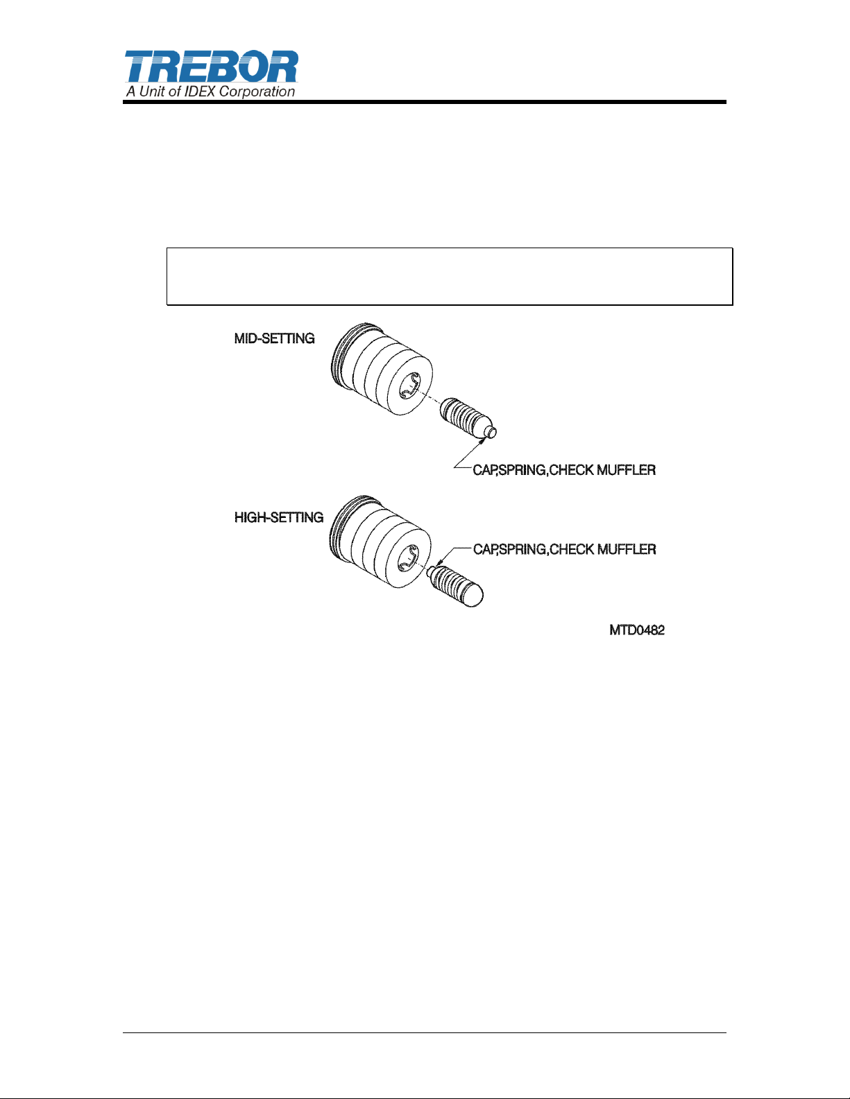
1.3.b Adjustment
The check muffler has 3 preset arrangements. The pump is shipped from the
factory in the medium back pressure setting, see Mid-Setting in Figure 1-2:
Check Muffler.
Mid-Setting
Start pressure <15 psi
Low flow applications (flow <3 gpm)
The Check Muffler is preset at the factory at the mid-setting. This setting
protects the pump air system from caustic fumes and allows the pump to
maintain a “Dead Head” condition with supply pressures up to 35 psi. This
setting also protects the pump in conditions of positive inlet supplies up to 10
ft. above the inlet of the pump.
High-Setting
Start pressure at <30 psi
Air supply >40 psi, low flow application (flow <3 gpm)
By removing the muffler from the pump and reversing the spring assembly in
the muffler then reinstalling the muffler, the Check Muffler is now set in the
highest back pressure setting. This setting protects the pump from dead
head conditions up to 60 psi, or from positive inlet heads up to 20 ft.
However, this setting is not recommended for operating fluid temperatures
over 60C as damage to the pump shaft can occur. This setting also
diminishes the pump’s flow capacity by 15% from normal published curves.
This setting also increases the pump start pressure from 15 psi to
approximately 30 psi.
Low-Setting (no picture shown)
Spring assembly removed
Start pressure <10 psi
Low back pressure, high flow (>3 gpm) requirement
MAGNUM 620R PUMP OPERATION / MAINTENANCE MANUAL PAGE 5
If none of the aforementioned conditions exist when operating the pump,
then the final setting of the check muffler may be used. To obtain maximum
flow capability and lowest start pressure (<10 psi), completely remove the
spring assembly from the check muffler assembly. This is the recommended
condition to obtain best performance and life from the pump. Most normal
open recirculation applications may be operated successfully under this
condition.
NOTE: Air consumption during “Dead Cycling” is very little since the pump
diaphragms are displacing only internal bypass. “Dead Cycling” should be
considered as a normal standby idle mode.
Figure 1-2: Check Muffler
PAGE 6 MAGNUM 620R PUMP OPERATION / MAINTENANCE MANUAL
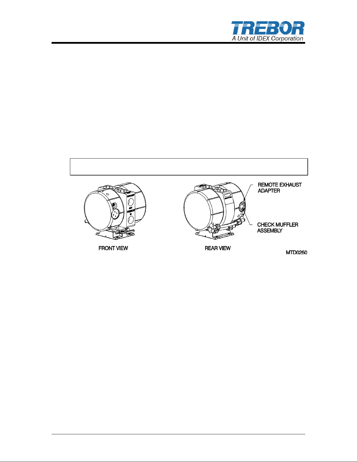
1.4 REMOTE EXHAUST HOOK-UP
Some installations may benefit from remotely exhausting air from the pump to
eliminate unwanted air turbulence or to prevent potentially damaging chemical
vapors from entering the pump air cavities.
Remove existing Muffler Assembly from the back of pump head.
Install Exhaust Plug in Exhaust Port.
Install the appropriately sized (3/8” OD) fitting and tubing (not provided) to
remote exhaust. A remote muffler assembly may be installed at the point of
exhaust if required for condition needing the check muffler (see Section
1.3.b).
NOTE: To maintain optimum pump performance use 3/8” (8mm) tubing minimum
at a length of 10 ft. (3 meters) maximum.
Figure 1-3: Remote Exhaust
MAGNUM 620R PUMP OPERATION / MAINTENANCE MANUAL PAGE 7
Available Options
A) Flare style tube adapter….1/2” and 3/4"
B) PFA tube stub out………...3/4"
C) Pillar Super 300…………..3/4” OR 1”
D) PFA Weldable pipe……….3/4"
Surge Suppressor
Assembled Height: IN (CM)
MODEL SS40
12.63 (32.08)
MODEL SS85
14.97 (38.02)
A)
B)
C)
D)
2 OPTIONS
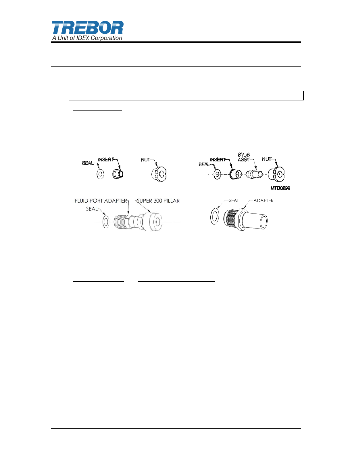
2.1 FLUID PORT CONNECTION OPTIONS
NOTE 1: Use O-ring to seal stainless steel or other rigid plumbing.
Figure 2-1
2.2 FLUID FITTINGS / SURGE SUPPRESSOR HOOK-UP
PAGE 8 MAGNUM 620R PUMP OPERATION / MAINTENANCE MANUAL

Figure 2-2
NOTE: See Surge Suppressor Operation Manual for detailed installation
instructions.
MAGNUM 620R PUMP OPERATION / MAINTENANCE MANUAL PAGE 9
 Loading...