

Trebor 620E User Manual

Phone: 800-669-1303 or 801-561-0303
Fax: 801-255-2312
e-mail: treborservice@idexcorp.com
MAGNUM 620E PUMP
External Control
Operation / Maintenance
Manual
SERIAL NUMBER (located on top of product):
PATENTS: U.S. 06106246, U.S. 6402486, U.S. 6695593, U.S. 65957952 04/11/2014– M620E-D

CONTENTS
1 INSTALLATION ............................................................................................................ 3
1.1 UNPACKING ...................................................................................................... 3
1.2 UTILITIES / HOOK-UP ....................................................................................... 3
2 OPTIONS ...................................................................................................................... 5
2.1 FLUID PORT CONNECTION OPTIONS ............................................................ 5
2.2 FLUID FITTINGS / SURGE SUPPRESSOR HOOK-UP .................................... 5
2.3 END OF STROKE (EOS) ASSEMBLY INSTALLATION .................................... 7
2.3.a Installation .............................................................................................. 7
2.3.b Signal Specifications .............................................................................. 8
2.4 PLC CONTROL SCHEMATIC ............................................................................ 9
2.5 LEAK PROBE OPTION .................................................................................... 10
2.5.a Installation ............................................................................................ 10
2.5.b Signal Specifications ............................................................................ 11
3 START-UP .................................................................................................................. 12
3.1 PERFORMANCE CHARTS .............................................................................. 12
4 MAINTENANCE .......................................................................................................... 15
4.1 PREVENTIVE MAINTENANCE SCHEDULE ................................................... 15
Preventive Maintenance Record ....................................................................... 17
4.2 RECOMMENDED SPARE PARTS ................................................................... 18
4.3 TOOLS .............................................................................................................. 18
4.4 PARTS ILLUSTRATION ................................................................................... 19
4.5 PARTS LIST ..................................................................................................... 20
4.6 DECONTAMINATION CLEAN-UP ................................................................... 20
4.7 DISASSEMBLY ................................................................................................. 21
4.7.a Head removal ...................................................................................... 21
4.7.b Body Disassembly ............................................................................... 22
4.8 CLEANING ....................................................................................................... 22
4.9 ASSEMBLY ....................................................................................................... 22
4.9.a Body Assembly .................................................................................... 22
4.9.b Final Assembly .................................................................................... 24
4.10 TESTING .......................................................................................................... 26
5 TROUBLESHOOTING ............................................................................................... 27
6 WARRANTY AND EXCLUSIONS .............................................................................. 28
7 CONTACT INFORMATION ........................................................................................ 29
7.1 GENERAL CONTACT INFORMATION ............................................................ 29
7.2 TECHNICAL SUPPORT ................................................................................... 29
7.3 REGIONAL REPRESENTATIVES ................................................................... 29
MAGNUM 620E PUMP OPERATION / MAINTENANCE MANUAL CONTENTS

Qty
Item
Description
1
620E
Magnum 620E Pump
1
M620E
Operation/Maintenance Manual
Optional Accessories:
1 or 2
DP-C-6
End-of-Stroke Probe
(1) Required for Cycle (2) Required for EOS
2
DP-L-32
Leak Probe
1 INSTALLATION
1.1 UNPACKING
After unpacking, the pump should be checked for any damage that may have
occurred during shipment. Damage should be reported to the carrier
immediately.
The following items should be included within the shipping container:
1.2 UTILITIES / HOOK-UP
It is recommended that the pump be positioned within 15° from level to maintain
self-priming ability and pumping efficiency. Allow sufficient room for tubing
connectors. The pump mounting is shown in Fig. 1-1 below.
Air connections are typically made using 3/8” OD x 1/4” ID tubing up to 12 ft. If
more distance is required it is recommended to increase tubing size to ½” tube
for the air lines to minimize losses.
Air Inlet: 3/8” FNPT (3/8” Dia. [8mm] supply tube minimum).
Air Supply: 20-80 psig (1.4 – 5.5 bar) clean dry air or nitrogen (see
Performance Charts, Section Error! Reference source not
found.).
Fluid Ports: 1” NPSM – additional adaptor port options available.
Inlet/Outlet adaptor fittings and Surge Suppressor require
torqueing during pump installation. See Section 2 for hook-up
diagram and torque values.
MAGNUM 620E PUMP OPERATION / MAINTENANCE MANUAL PAGE 3
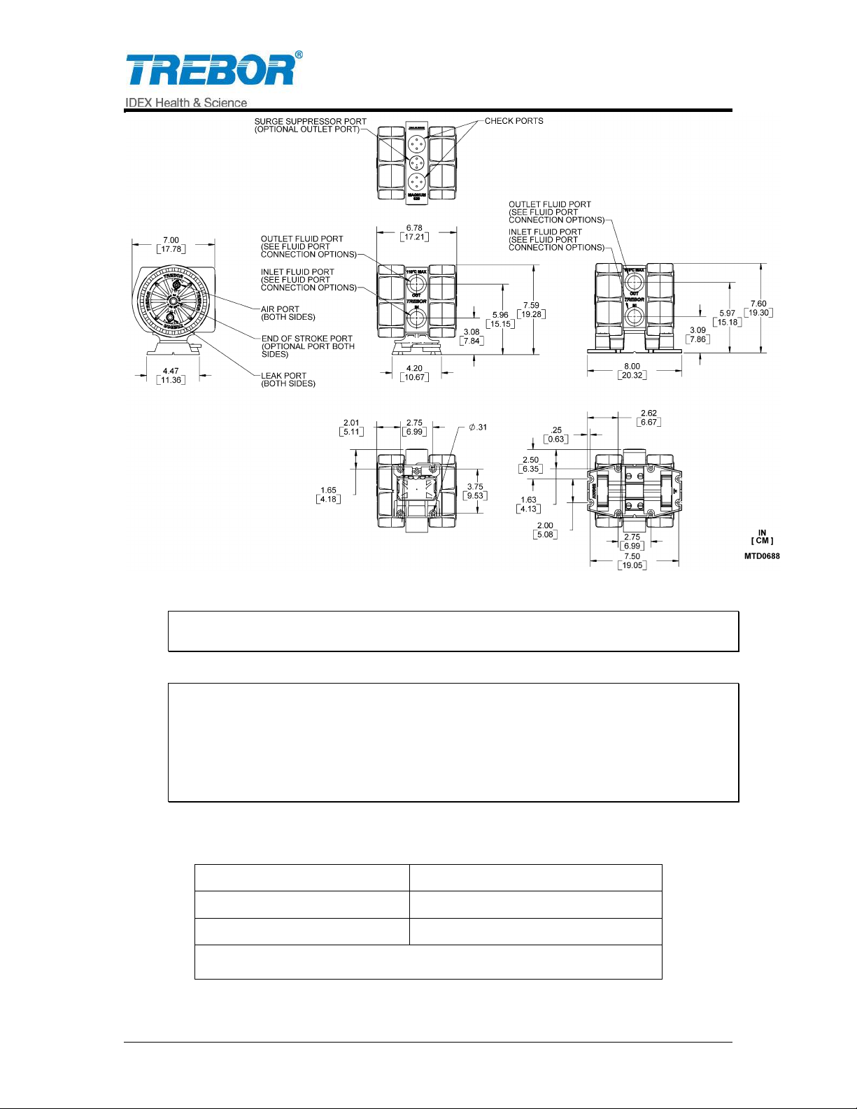
Temperature Range
Supply Pressure Max
< 60°C
80 PSI (5.5 bar)
60°C - 110°C**
60 PSI (4.1 bar)
*110C Maximum Fluid Temperature
Figure 1-1 Pump Dimensions (Standard & Optional Quick Change Base)
ATTENTION: The pump should be operated with clean, dry air or nitrogen.
Particulate, water and oils in the air supply can damage the pump.
NOTE:
1. It is recommended that a filter be placed on the discharge side of the pump.
2. Although extensive efforts are made to deliver pumps to our customers
completely dry, new pumps may contain residual moisture from their final DI
water test.
Recommended Maximum Operating Levels:
PAGE 4 MAGNUM 620E PUMP OPERATION / MAINTENANCE MANUAL
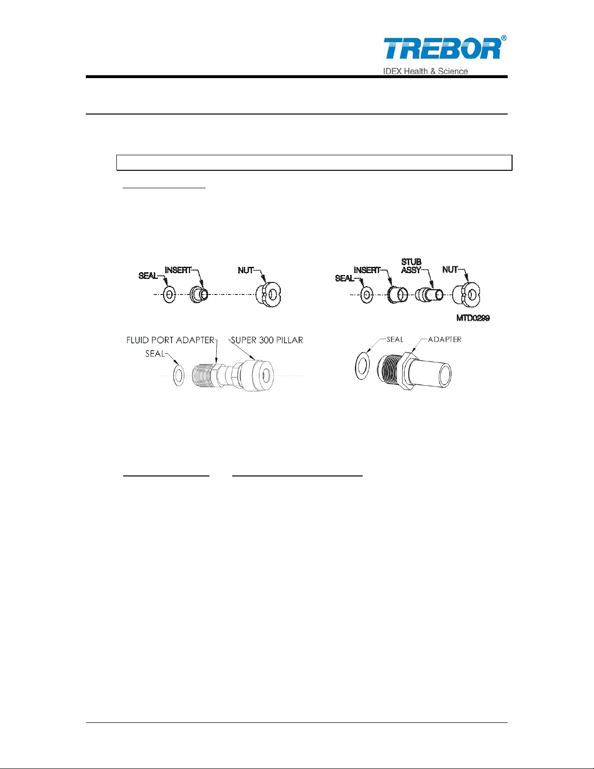
Available Options
A) Flare style tube adapter….1/2” and 3/4"
B) PFA tube stub out………...3/4"
C) Pillar Super 300…………..3/4” OR 1”
D) PFA Weldable pipe……….3/4"
Surge Suppressor
Assembled Height: IN (CM)
MODEL SS40
12.63 (32.08)
MODEL SS85
14.97 (38.02)
A)
B)
C)
D)
2 OPTIONS
2.1 FLUID PORT CONNECTION OPTIONS
NOTE 1: Use O-ring to seal stainless steel or other rigid plumbing.
Figure 2-1
2.2 FLUID FITTINGS / SURGE SUPPRESSOR HOOK-UP
MAGNUM 620E PUMP OPERATION / MAINTENANCE MANUAL PAGE 5
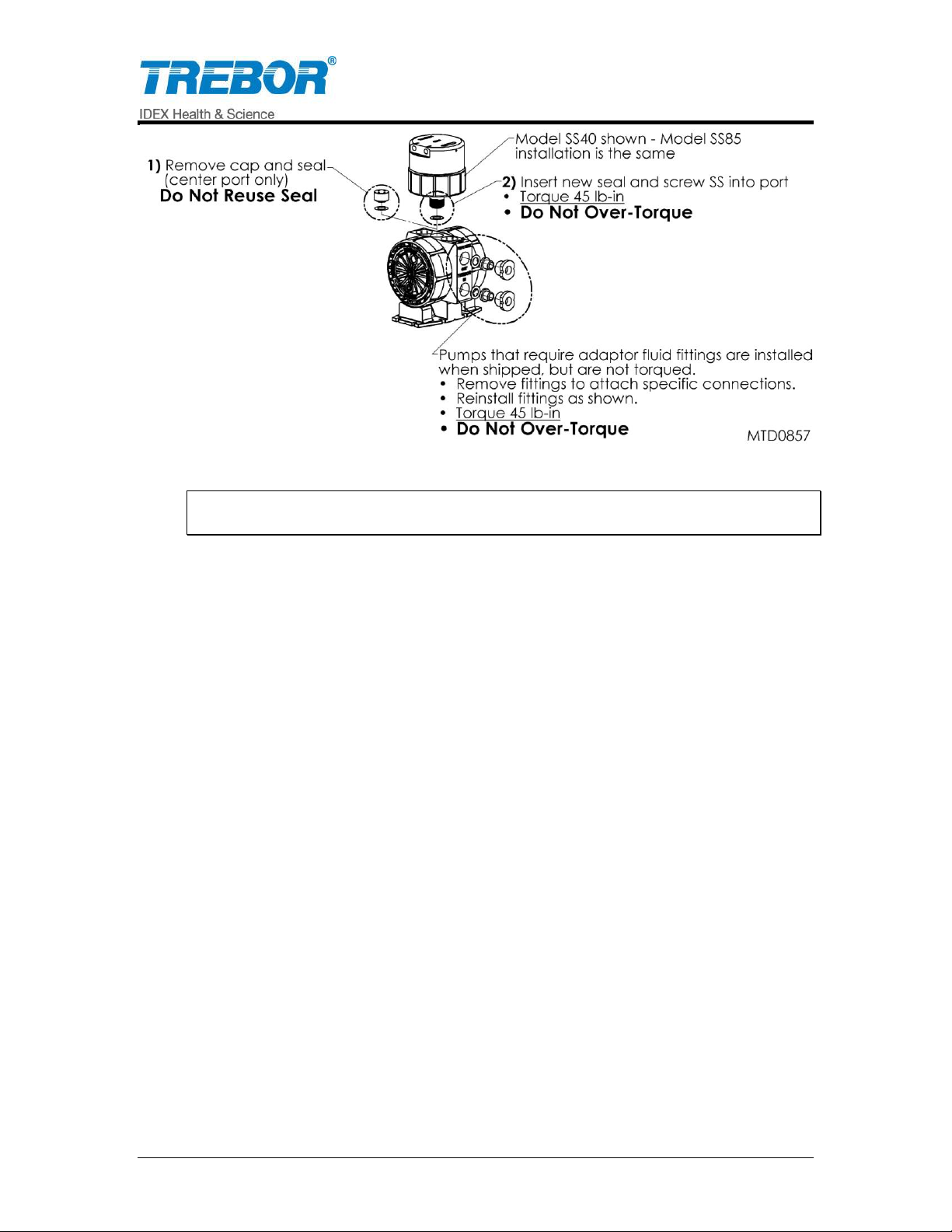
Figure 2-2
NOTE: See Surge Suppressor Operation Manual for detailed installation
instructions.
PAGE 6 MAGNUM 620E PUMP OPERATION / MAINTENANCE MANUAL
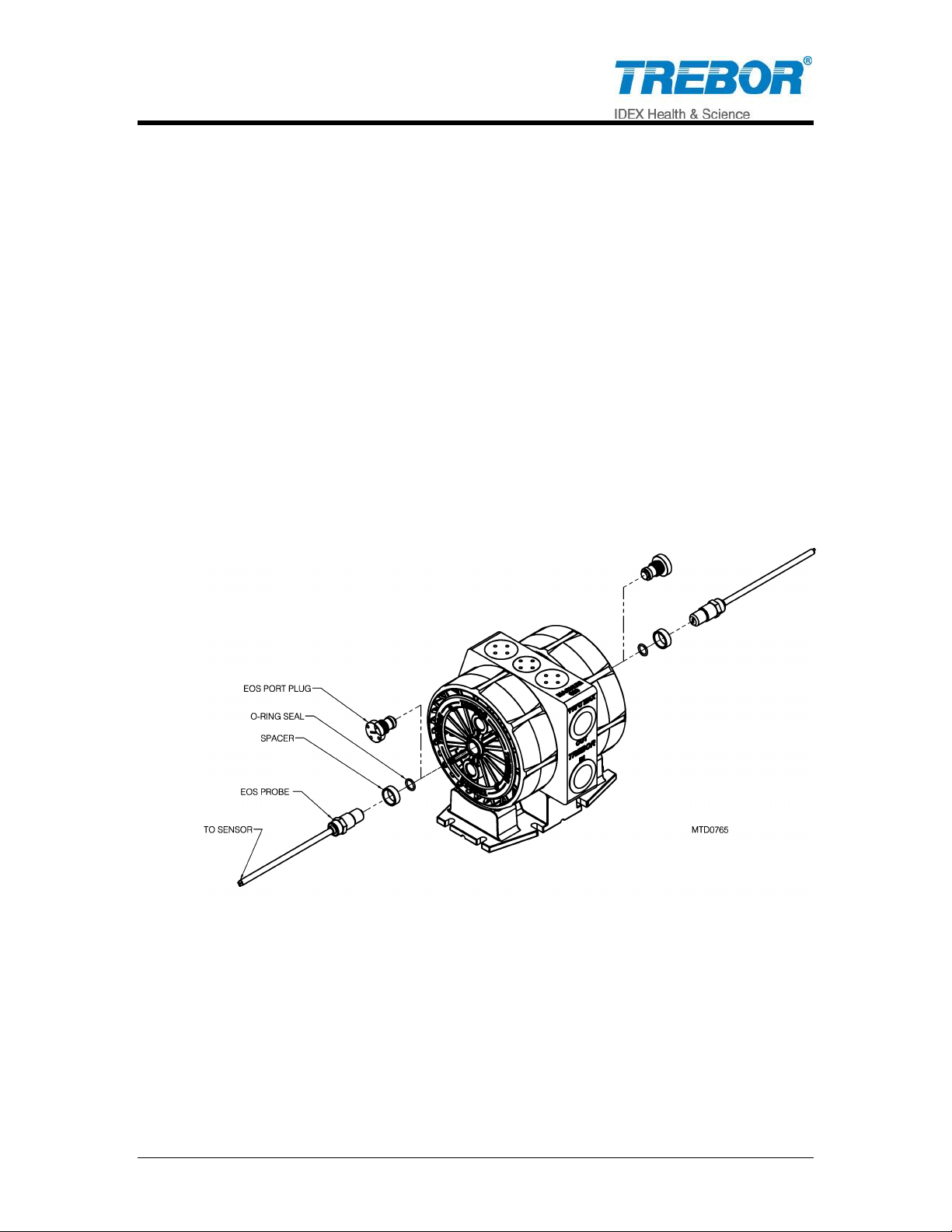
2.3 END OF STROKE (EOS) ASSEMBLY INSTALLATION
EOS probes use fiber optic cable (Acrylic Optic Cable: 1mm core) attached to an
optic sensor that transmits light in order to detect diaphragm end of stroke within
the air chambers.
2.3.a Installation
Remove Center Port Plug.
Install o-ring seal into center port.
Install Spacer onto probe.
Install EOS probe assembly into port.
Thread probe fitting into head and tighten until spacer is flush with head
surface.
Connect fiber optic cable to optic amplifier. NOTE: Limit bends in fiber optic
cable to 1” radius minimum to help ensure optimum signal strength. NOTE:
Standard cable length is 12.5 ft. [4 meters].
Figure 2-3
MAGNUM 620E PUMP OPERATION / MAINTENANCE MANUAL PAGE 7
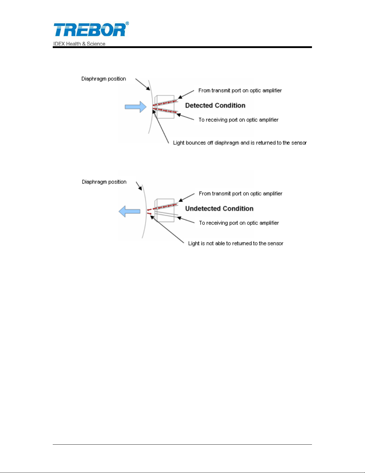
2.3.b Signal Specifications
Figure 2-4
PAGE 8 MAGNUM 620E PUMP OPERATION / MAINTENANCE MANUAL
Note: The use of ONE EOS probe is applicable for cycle counting to monitor pump
operation and monitor cycles for maintenance intervals. To control pump cycling
requires 2 EOS probes and amplifiers.
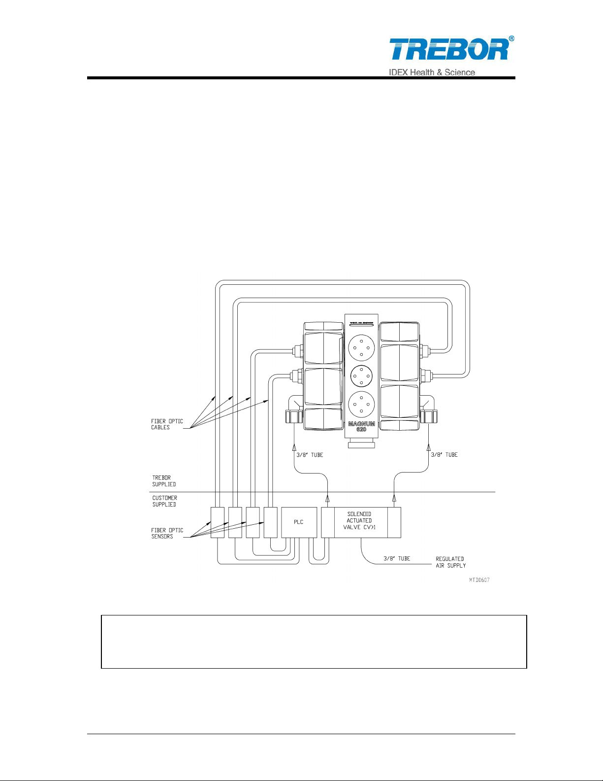
2.4 PLC CONTROL SCHEMATIC
Shown below is an example of a Programmable Logic Controller (PLC) control
schematic shown will allow the Magnum to be controlled by a PLC for the
Magnum pump. Some of the features that can be programmed are:
Start and stop pump
Monitoring approximate flow rate (contact factory for displacement factors)
Leak sensing (section 2.5)
Preventative maintenance counter
Cycle counting or End-of-Stroke detection
Oscillator control override
Figure 2-5
MAGNUM 620E PUMP OPERATION / MAINTENANCE MANUAL PAGE 9
 Loading...