

Trebor 620D User Manual
Phone: 800-669-1303 or 801-561-0303
Fax: 801-255-2312
e-mail: treborservice@idexcorp.com
MAGNUM 620D PUMP
Operation / Maintenance
Manual
SERIAL NUMBER (located on back of product):
PATENTS: U.S. 09642426, U.S. 06106246, U.S. 05971402, U.S. 05370507 04/10/2014– M620D-B

CONTENTS
1 INSTALLATION ............................................................................................................ 3
1.1 UNPACKING ...................................................................................................... 3
1.2 UTILITIES / HOOK-UP ....................................................................................... 3
2 OPTIONS ...................................................................................................................... 5
2.1 FLUID PORT CONNECTION OPTIONS ............................................................ 5
2.2 FLUID FITTINGS / SURGE SUPPRESSOR HOOK-UP .................................... 5
3 START-UP .................................................................................................................... 7
3.1 PERFORMANCE CHARTS ................................................................................ 7
4 MAINTENANCE .......................................................................................................... 10
4.1 PREVENTIVE MAINTENANCE SCHEDULE ................................................... 10
4.1.a Preventive Maintenance Record .......................................................... 12
4.2 RECOMMENDED SPARE PARTS ................................................................... 13
4.3 TOOLS .............................................................................................................. 13
4.4 PARTS ILLUSTRATION ................................................................................... 14
4.5 PARTS LIST ..................................................................................................... 15
4.6 CLEAN-UP ........................................................................................................ 15
4.7 DISASSEMBLY ................................................................................................. 16
4.7.a Body Disassembly ............................................................................... 17
4.7.b Head Disassembly ............................................................................... 17
4.7.c Master Head Disassembly ................................................................... 17
4.7.d Pump Cleaning .................................................................................... 17
4.8 ASSEMBLY ....................................................................................................... 17
4.8.a Master Head Assembly ........................................................................ 18
4.8.b Pump Assembly ................................................................................... 19
4.8.c Final Assembly .................................................................................... 21
4.9 TESTING .......................................................................................................... 22
5 TROUBLESHOOTING ............................................................................................... 23
6 WARRANTY ............................................................................................................... 24
7 CONTACT INFORMATION ........................................................................................ 25
7.1 GENERAL CONTACT INFORMATION ............................................................ 25
7.2 TECHNICAL SUPPORT ................................................................................... 25
7.3 REGIONAL REPRESENTATIVES ................................................................... 25
MAGNUM 620D PUMP OPERATION / MAINTENANCE MANUAL CONTENTS

Qty
Item
Description
1
620
Magnum 620 Pump
1
M620D
Operation/Maintenance Manual
1 INSTALLATION
1.1 UNPACKING
After unpacking, the pump should be checked for any damage that may have
occurred during shipment. Damage should be reported to the carrier
immediately.
The following items should be included within the shipping container:
1.2 UTILITIES / HOOK-UP
It is recommended that the pump be positioned within 15 from level to maintain
self-priming ability and pumping efficiency. Allow sufficient room for tubing
connectors. The pump mounts on a quick-change base for easy installation.
The pump has an exhaust location on the backsides of the master and slave
heads. The exhaust location requires 1/2” (12mm) minimum clearance behind
the master head. Care should be taken to prevent flooding the exhaust port
when the pump is located in a wet bench plenum. For remote exhaust
connection see Section Error! Reference source not found..
Air Inlet: 1/4” FNPT (3/8” Dia. [8mm] supply tube minimum).
Air Supply: 28-80 psig (1.7 – 5.5 bar) clean dry air or nitrogen (see
Performance Charts, Section 3.1).
Fluid Ports: 1” NPSM – additional adaptor port options available.
Inlet/Outlet adaptor fittings and Surge Suppressor require
torqueing during pump installation. See Section 2 for hook-up
diagram and torque values.
MAGNUM 620D PUMP OPERATION / MAINTENANCE MANUAL PAGE 3
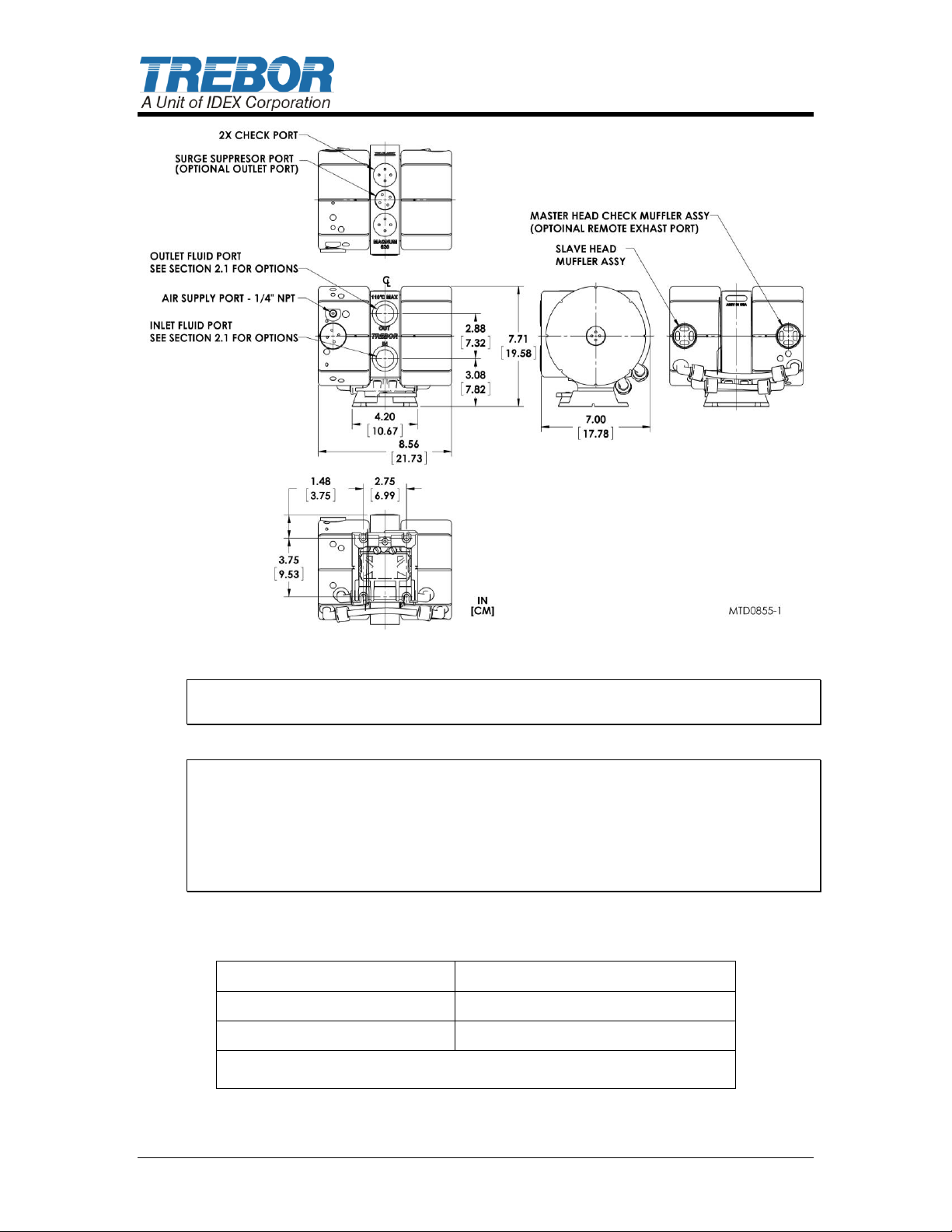
Temperature Range
Supply Pressure Max
< 60°C
80 PSI (5.5 bar)
60°C - 100°C**
60 PSI (4.1 bar)
*100C Maximum Fluid Temperature
Figure 1-1: Dimensional Views
ATTENTION: The pump should be operated with clean, dry air or nitrogen.
Particulate, water and oils in the air supply can damage the pump.
NOTE:
1. It is recommended that a filter be placed on the discharge side of the pump.
2. Although extensive efforts are made to deliver pumps to our customers
completely dry, new pumps may contain residual moisture from their final DI
water test.
Recommended Maximum Operating Levels:
PAGE 4 MAGNUM 620D PUMP OPERATION / MAINTENANCE MANUAL
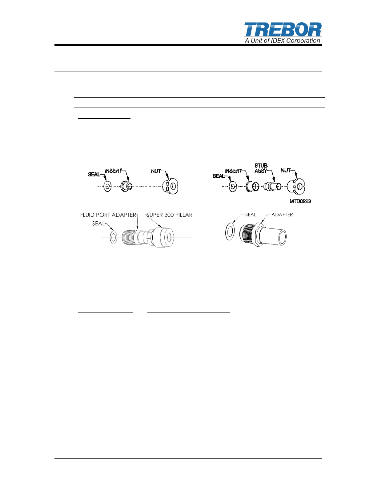
Available Options
A) Flare style tube adapter….1/2” and 3/4"
B) PFA tube stub out………...3/4"
C) Pillar Super 300…………..3/4” OR 1”
D) PFA Weldable pipe……….3/4"
Surge Suppressor
Assembled Height: IN (CM)
MODEL SS40
12.63 (32.08)
MODEL SS85
14.97 (38.02)
A)
B)
C)
D)
2 OPTIONS
2.1 FLUID PORT CONNECTION OPTIONS
NOTE 1: Use O-ring to seal stainless steel or other rigid plumbing.
Figure 2-1
2.2 FLUID FITTINGS / SURGE SUPPRESSOR HOOK-UP
MAGNUM 620D PUMP OPERATION / MAINTENANCE MANUAL PAGE 5
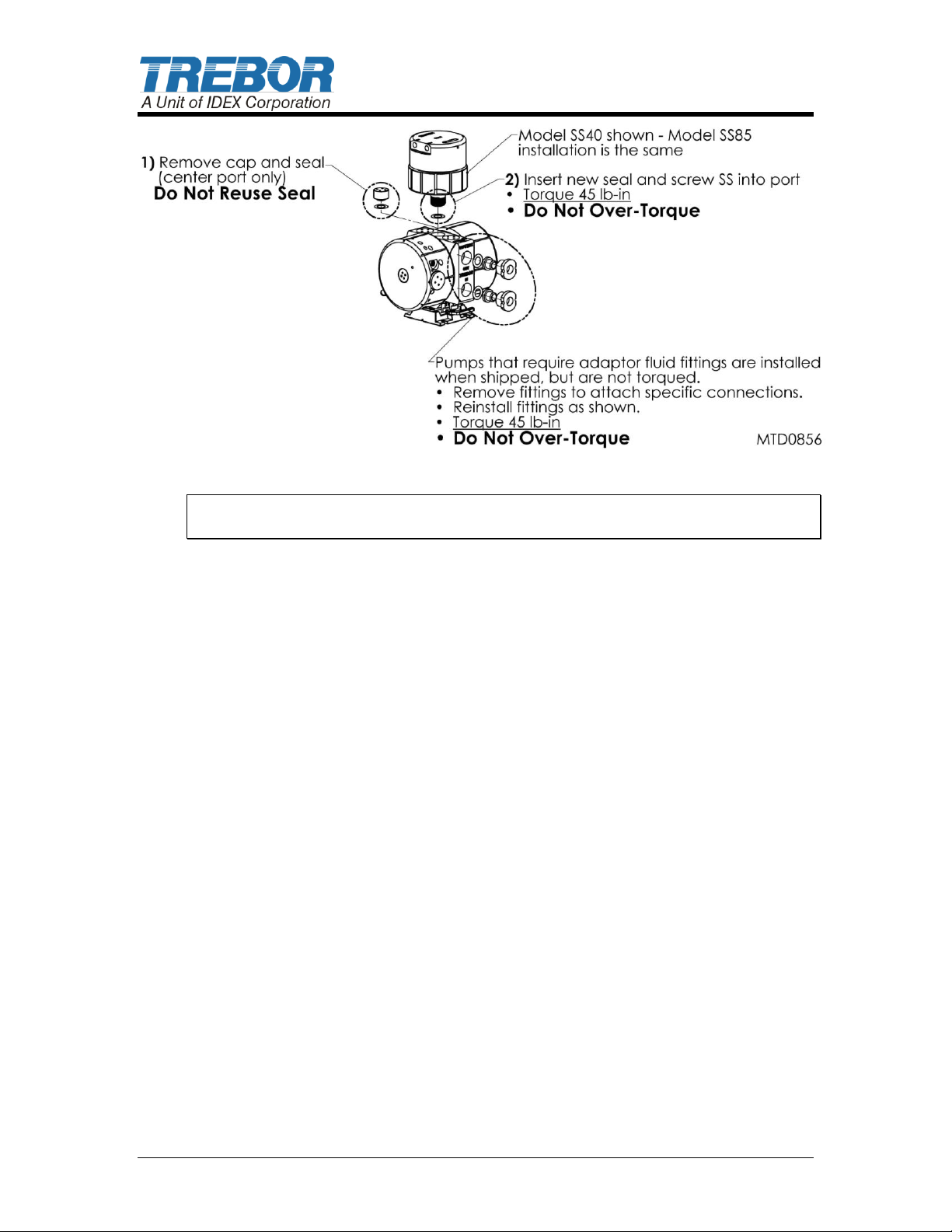
Figure 2-2
NOTE: See Surge Suppressor Operation Manual for detailed installation
instructions.
PAGE 6 MAGNUM 620D PUMP OPERATION / MAINTENANCE MANUAL
3 START-UP
Pump air supply pressure must be regulated. (See Figure 3-2: Pressure vs.
Fluid Temperature Chart.)
Open the fluid suction (IN) line valve, if necessary.
Open the fluid discharge (OUT) line valve, if necessary.
Start slowly with air regulator at low (> 25 psi) pressure setting. Increase
pressure to attain desired flow, up to the maximum rating (See Section 3.1).
Refer to Troubleshooting, Section 5, if pump fails to start.
ATTENTION: Prolonged periods (> 5 minutes) of dry running can damage
critical internal pump parts.
CAUTION: When handling potentially dangerous fluids under pressure,
the pump and its fittings should be placed in an enclosure away from operators.
3.1 PERFORMANCE CHARTS
Pumping capacity is a function of air supply pressure and volume, suction head,
suction line restrictions, discharge head, discharge line restriction, and fluid
specific gravity and viscosity.
NOTE: Specification to be used to size regulators and control valves.
MAGNUM 620D PUMP OPERATION / MAINTENANCE MANUAL PAGE 7
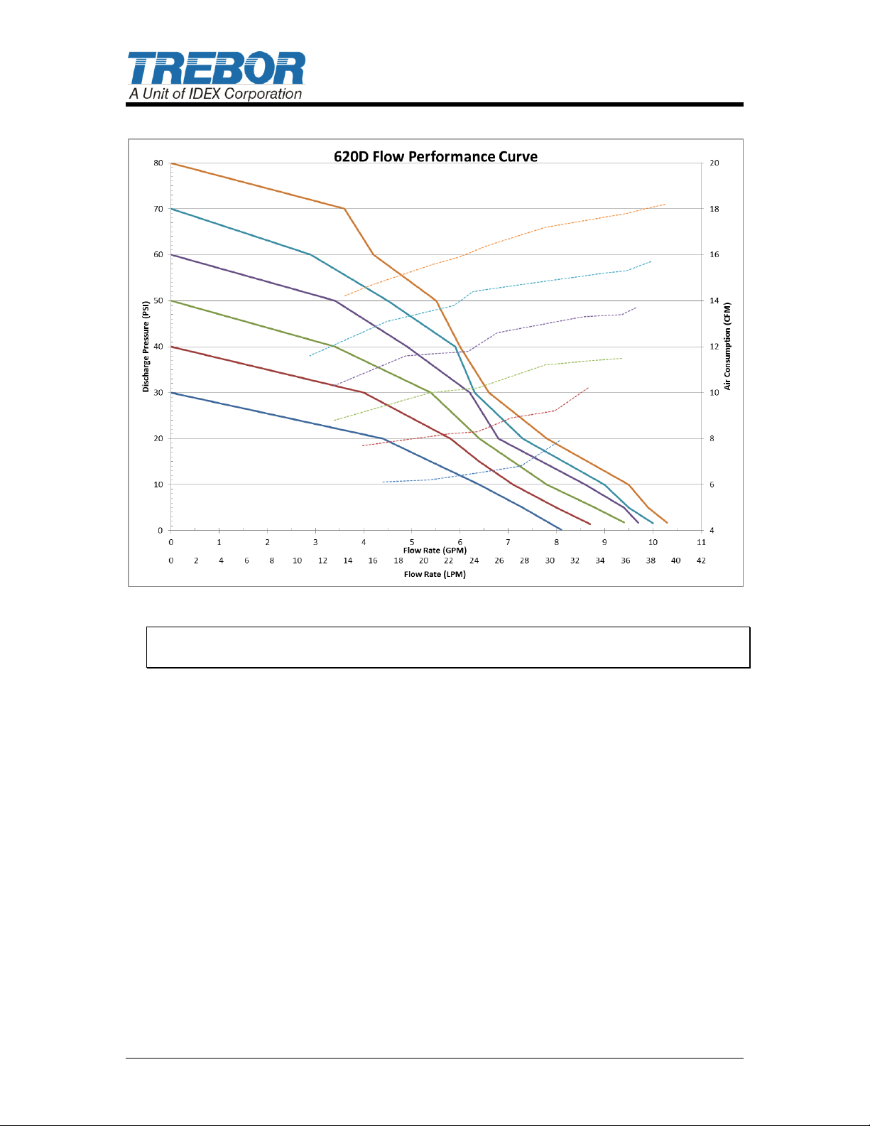
Figure 3-1: Flow Performance
NOTE: Test information is based on specific conditions and limited sampling. Use
for general reference only.
PAGE 8 MAGNUM 620D PUMP OPERATION / MAINTENANCE MANUAL
 Loading...