

Trebor 55E User Manual
Phone: 800-669-1303 or 801-561-0303
Fax: 801-255-2312
Email: treborservice@idexcorp.com
EVOLVE 55E PUMP
Operation / Maintenance Manual
http://www.treborintl.com
SERIAL NUMBER (located on back of product):
PATENTS: U.S.05971402, U.S.05370507, U.S.06106246, U.S.13/536,439 5/13/14 – ME55E-A

CONTENTS
1 INSTALLATION ........................................................................................................... 3
1.1 UNPACKING ...................................................................................................... 3
1.2 UTILITIES / CONNECTION ............................................................................... 3
1.3 OPTIONAL END-OF-STROKE PROBE INSTALLATION .................................. 5
1.4 REMOTE EXHAUST CONNECTION ................................................................ 5
2 OPTIONS ...................................................................................................................... 7
2.1 FLUID PORT CONNECTION OPTIONS ........................................................... 7
2.2 FLUID FITTINGS / SURGE SUPPRESSOR CONNECTION ............................ 7
2.3 OPTIONAL LEAK SENSING .............................................................................. 8
2.3.a Installation ............................................................................................. 8
2.3.b Sensor Signal Specifications ................................................................ 8
3 START-UP .................................................................................................................. 10
3.1 PERFORMANCE CHARTS ............................................................................. 10
4 MAINTENANCE ......................................................................................................... 13
4.1 PREVENTIVE MAINTENANCE SCHEDULE .................................................. 13
4.1.a Preventive Maintenance Record ......................................................... 14
4.2 RECOMMENDED SPARE PARTS .................................................................. 15
4.3 TOOLS ............................................................................................................. 15
4.4 PARTS ILLUSTRATION .................................................................................. 16
4.5 PARTS LIST ..................................................................................................... 17
4.6 CLEAN-UP ....................................................................................................... 17
4.7 DISASSEMBLY ................................................................................................ 18
4.7.a Head Removal .................................................................................... 18
4.7.b Body Disassembly ............................................................................... 19
4.7.c Control Base Disassembly .................................................................. 19
4.7.d Pump Cleaning .................................................................................... 19
4.8 ASSEMBLY ...................................................................................................... 19
4.8.a Control Base Assembly ....................................................................... 20
4.8.b Body Assembly ................................................................................... 20
4.8.c Head and Body Assembly ................................................................... 22
4.8.d Final Assembly .................................................................................... 22
4.9 TESTING .......................................................................................................... 23
4.9.a Performance Test ................................................................................ 23
4.9.b Pump Drying Procedure ...................................................................... 24
4.9.c Dry Suction Test .................................................................................. 24
5 TROUBLESHOOTING ............................................................................................... 25
6 WARRANTY .............................................................................................................. 26
7 CONTACT INFORMATION ........................................................................................ 28
7.1 GENERAL CONTACT INFORMATION ........................................................... 28
7.2 TECHNICAL SUPPORT .................................................................................. 28
7.3 REGIONAL REPRESENTATIVES ................................................................... 28
EVOLVE 55E PUMP OPERATION / MAINTENANCE MANUAL CONTENTS

Qty
Item
Description
1
Pump
Evolve 55E Pump
1
ME55E
Operation/Maintenance Manual
1 INSTALLATION
1.1 UNPACKING
After unpacking, the pump should be checked for any damage that may have occurred
during shipment. Damage should be reported to the carrier immediately.
Although extensive efforts are made to deliver pumps to our customers completely dry, new
pumps may contain residual moisture from their final DI water test.
The following items should be included within the shipping container:
1.2 UTILITIES / CONNECTION
It is recommended that the pump be positioned within 15 from level to maintain self-priming
ability and pumping efficiency. Allow sufficient room for tubing connectors. The pump
mounts on a quick-change base for easy installation.
The pump has dual exhaust locations on the backside of the base. The exhaust locations
require 1/2” (12mm) minimum clearance behind the control base. Care should be taken to
elevate the pump whenever possible to help prevent flooding when the pump is located in a
wet bench plenum. For remote exhaust connection, see Section 1.4.
Air Inlet: 1/4” FNPT (3/8” Dia. [8mm] supply tube minimum).
Air Supply: 20-100 psig (.14 - .69 MPa) clean dry air or nitrogen (see Performance
Charts, Section 3.1).
Fluid Ports: Inlet/Outlet fluid fittings and surge suppressor require torquing during pump
installation. See Section 2 for connection diagram and torque values.
EVOLVE 55E PUMP OPERATION / MAINTENANCE MANUAL PAGE 3

Figure 1-1: Dimensional Views
ATTENTION: The pump should be operated with clean, dry air or nitrogen. Particulate,
water, and oils in the air supply can damage the pump.
NOTE:
It is recommended that a filter be placed on the discharge side of the pump.
PAGE 4 EVOLVE 55E PUMP OPERATION / MAINTENANCE MANUAL
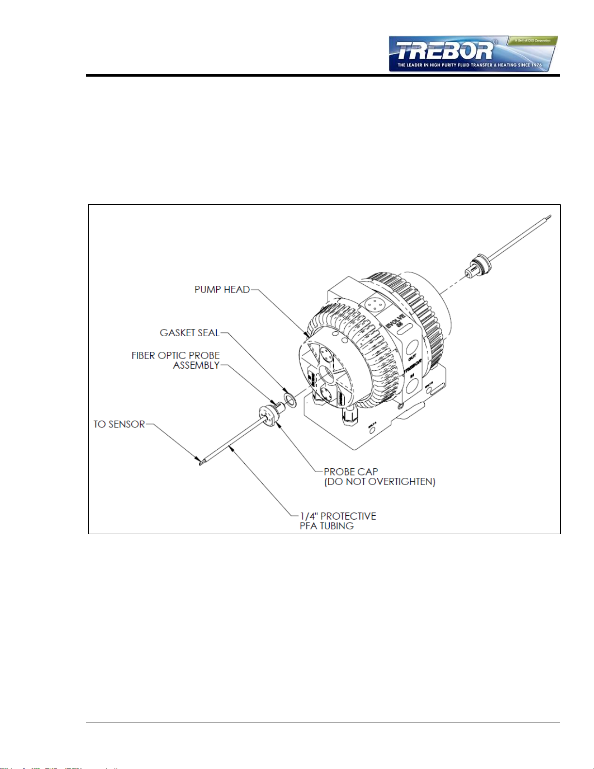
1.3 OPTIONAL END-OF-STROKE PROBE INSTALLATION
Optic Cable: 1mm core; 1/4” PFA protective tubing.
Install seal into head.
Install probe assembly into head.
Thread probe cap into head hand tight only. No tool needed.
Connect fiber optic cable to sensor. NOTE: Minimize bends in fiber optic cable to 2”
radius minimum to help ensure optimum signal strength.
Figure 1-2: End-of-Stroke Sensor Installation
1.4 REMOTE EXHAUST CONNECTION
Some installations may benefit from remotely exhausting air from the pump to eliminate
unwanted air turbulence or to prevent potentially damaging chemical vapors from entering
the pump air cavities.
Remove existing Muffler Assemblies from the pump base.
Replace Muffler Assemblies with Exhaust Plug
Remove Pipe Plug (¼” NPT) from the pump base. Install the appropriately sized
fitting and tubing (not provided) to remote exhaust.
EVOLVE 55E PUMP OPERATION / MAINTENANCE MANUAL PAGE 5
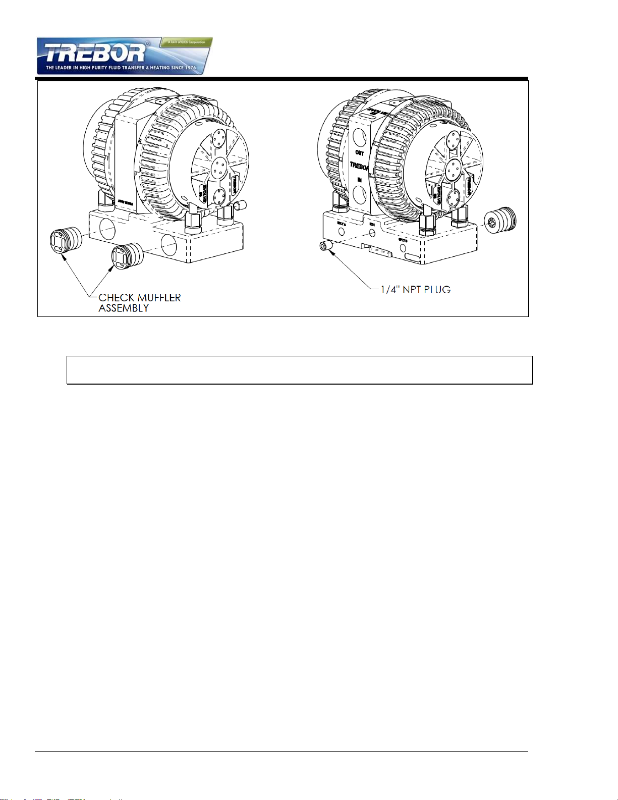
NOTE: To maintain optimum pump performance use 3/8” (8mm) tubing minimum at a length
of 10 ft. (3 meters) maximum.
Figure 1-3: Remote Exhaust Connection
PAGE 6 EVOLVE 55E PUMP OPERATION / MAINTENANCE MANUAL
Available Options
A)
Perlast O-Ring Adapter
B)
PTFE Gasket Adapter
Surge Suppressor
Assembled Height: mm (IN)
MODEL SS40
373 (14.7)
MODEL SS85
435 (17.1)
MODEL SS95
356 (14.0)
2 OPTIONS
2.1 FLUID PORT CONNECTION OPTIONS
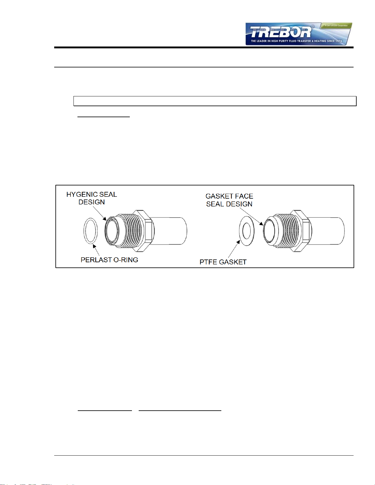
NOTE 1: Use O-ring to seal stainless steel or other rigid plumbing.
The Evolve 55 pump uses molded ultrapure PFA fluid port adapters. Two types of adapters
are available: one with a Perlast o-ring and one using a PTFE gasket. Both adapters end in
a ¾” pipe. The adapter can be ordered with a standard pipe or tube fitting (see below for
options) or can be customized to fit any facility piping. Figure 2-1 shows the fluid port
adapters
Figure 2-1: Perlast O-ring and PTFE Gasket Fluid Port Adapters
Available Pipe Connection Fittings:
¾” Pipe Stubout
¾” Tube Stubout
½” Flare Fitting
¾” Flare Fitting
1” Flare Fitting
¾” Pillar Fitting
¾” Female NPT Fitting
These fittings can be ordered with either the Perlast O-ring adapter or the PTFE Gasket
adapter. If additional pipe fitting types are needed, contact your sales associate. Custom
configurations are available to adapt the Evolve 55 to any facility configuration.
2.2 FLUID FITTINGS / SURGE SUPPRESSOR CONNECTION
EVOLVE 55E PUMP OPERATION / MAINTENANCE MANUAL PAGE 7

Figure 2-2: Generic Connection Diagram
NOTE: See Surge Suppressor Operation Manual for detailed installation instructions.
2.3 OPTIONAL LEAK SENSING
2.3.a Installation
Remove plug and seal from port. Probe is self-sealing.
Install probe assembly into leak sensor port.
Thread probe cap into port. (NOTE: Do not over tighten; damage to threads will occur.)
Push protective tubing into probe cap.
Connect fiber optic cable to sensor (NOTE: Minimize bends in fiber optic cable to 2”
radius minimum to help ensure optimum signal strength.) Fiber optic cable can be cut to
desired length using the cable cutter provided.
2.3.b Sensor Signal Specifications
The sensor signal is normally closed. In the event of a leak, no light signal is returned to
the sensor.
NOTE: See your fiber optic sensor installation instructions for proper connection and
adjustment.
PAGE 8 EVOLVE 55E PUMP OPERATION / MAINTENANCE MANUAL
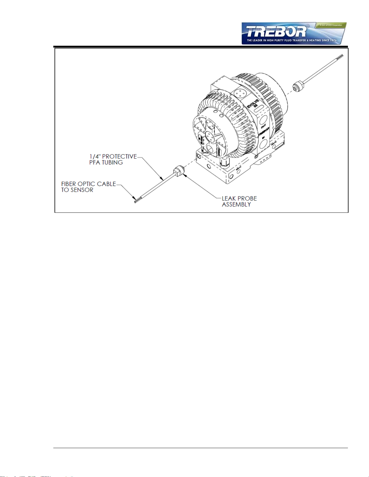
Figure 2-3: Leak Probe Assembly
EVOLVE 55E PUMP OPERATION / MAINTENANCE MANUAL PAGE 9
 Loading...