


YSD 240F
Trane YSD 155F, YHD 155F, YSH 155F, YHH 155F, YSD 180F Installation, Operation And Maintenance Manual
...
Installation, Operation,
and Maintenance
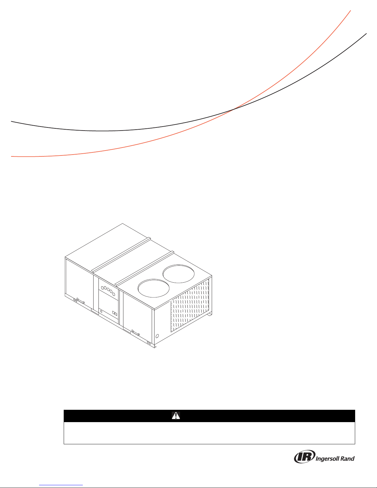
Packaged Rooftop Air Conditioners
Voyager™
– Gas/ Electric
12½ – 25 Tons, 60/50Hz
Model Number:
Only qualified personnel should install and service the equipment. The installation, starting up, and servicing of heating, ventilating, and airconditioning equipment can be hazardous and requires specific knowledge and training. Improperly installed, adjusted or altered equipment
by an unqualified person could result in death or serious injury. When working on the equipment, observe all pre cautions in the literature and
on the tags, stickers, and labels that are attached to the equipment.
May 2014
YS*150–300
YH*150-300
SAFETY WARNING
RT-SVX26K-EN
Warnings, Cautions and Notices
Warnings, Cautions and Notices. Note that warnings,
cautions and notices appear at appropriate intervals
throughout this manual. Warnings are provide to alert
installing contractors to potential hazards that could result
in personal injury or death. Cautions are designed to alert
personnel to hazardous situations that could result in
personal injury, while not ices indicate a situation that may
result in equipment or property-damage-only accidents.
Your personal safety and the proper operation of this
machine depend upon the strict observance of these
precautions.
ATTENTION: Warnings, Cautions and Notices appear at
appropriate sections throughout this literature. Read
these carefully:
WARNING
CAUTIONs
NOTICE:
Indicates a potentially hazardous
situation which, if not avoided, could
result in death or serious injury.
Indicates a potentially hazardous
situation which, if not avoided, could
result in minor or moderate injury. It
could also be used to alert against
unsafe practices.
Indicates a situation that could result in
equipment or property-damage only
Important
Environmental Concerns!
Scientific research has shown that certain man-made
chemicals can affect the earth’s naturally occurring
stratospheric ozone layer when released to the
atmosphere. In particular, several of the identified
chemicals that may af fect the ozone layer are refrigerants
that contain Chlorine, Fluorine and Carbon (CFCs) and
those containing Hydrogen, Chlorine, Fluorine and
Carbon (HCFCs). Not all refrigerants containing these
compounds have the same potential impact to the
environment. T rane advocates the responsible handling of
all refrigerants-including industry replacements for CFCs
such as HCFCs and HFCs.
Responsible Refrigerant Practices!
Trane believes that responsible refrigerant practices are
important to the environment, our customers, and the air
conditioning industry. All technicians who handle
refrigerants must be certified. The Federal Clean Air Act
(Section 608) sets forth the requirements for handling,
reclaiming, recovering and recycling of certain
refrigerants and the equipment that is used in these
service procedures. In addition, some states or
municipalities may have additional requirements that
must also be adhered to for responsible management of
refrigerants. Know the applicable laws and follow them.
Personal Protective Equipment (PPE)
Required!
Installing/servicing this unit could result in exposure to
electrical, mechanical and chemical hazards.
• Before installing/servi cin g th is un it, technicians
MUST put on all PPE required for the work being
undertaken (Examples; cut r esistant glov es/sleev es,
butyl gloves, safety glasses, hard hat/bump cap, fall
protection, electrical PPE and arc flash clothing).
ALWAYS refer to appropriate Material Safety Data
Sheets (MSDS)/Safety Data Sheets (SDS) and OSHA
guidelines for proper PPE.
• When workin g with or around hazardous c hemicals,
ALWAYS refer to the appropriate MSDS/SDS and
OSHA/GHS (Global Harmonized System of
Classification and Labelling of Chemicals) guidelines
for information on allowable personal exposure
levels, proper respiratory protection and handling
instructions.
• If there is a risk of ener gized electrical contact, ar c, or
flash, technicians MUS T put on all PPE in accordance
with OSHA, NFPA 70E, or other country-specific
requirements for arc flash protection, PRIOR to
servicing the unit. NEVER PERFORM ANY
SWITCHING, DISCONNECTING, OR VOLTAGE
TESTING WITHOUT PROPER ELECTRICAL PPE AND
ARC FLASH CLOTHING. ENSURE ELECTRICAL
METERS AND EQUIPMENT ARE PROPERLY RATED
FOR INTENDED VOLTAGE.
Failure to follow instructions could result in death or
serious injury.
Proper Field Wiring and Grounding
Required!
All field wiring MUST be performed by qualified
personnel. Improperly installed and grounded field
wiring poses FIRE and ELECTROCUTION hazards. To
avoid these hazards, y ou MUST follo w requir ements for
field wiring installation and grounding as described in
NEC and your local/state electrical codes. Failure to
follow code could result in death or serious injury.
WARNING
WARNING
© 2014 Trane All rights reserved RT-SVX26K-EN
NOTICE:
Water Damage!
Non-factory penetrations through the base of this unit
are not allowed. Any penetration in the base of the unit
may aff ect the water tight integrity of the unit and lead
to water leaks in to the conditioned space. Failure to
follow instructions could result in equipment and
property damage.
Overview of Manual
Note: One copy of this document ships inside the control
panel of each unit and is customer property . It must
be retained by the unit’s maintenance personnel.
This booklet describes proper installation, operation, and
maintenance procedures for air cooled systems.
By carefully reviewing the information within this manual
and following the instructions, the risk of improper
operation and/or component dama ge will be minimized.
It is important that periodic maintenance be performed to
help assure trouble free operation. A maintenance
schedule is provided at the end of this manual.
Should equipment failure occur, contact a qualified
service organization with qualified, experienced HVAC
technicians to properly diagnose and repair this
equipment.
Warnings, Cautions and Notices
Revision Summary
RT-SVX26K-EN (27 May 2014)
• New Low Leak Economizer & Fault Detection
Diagnostics (FDD) Options
• Updated Model Number Description Section
• Added back Warranty Section
RT-SVX26K-EN 3

Table of Contents
Model Number Description . . . . . . . . . . . . . . . 5
General Information . . . . . . . . . . . . . . . . . . . . . 7
Unit Description . . . . . . . . . . . . . . . . . . . . . . . 7
System Input Devices & Functions . . . . . . . 7
Sensors . . . . . . . . . . . . . . . . . . . . . . . . . . . . . . 9
Unit Inspection . . . . . . . . . . . . . . . . . . . . . . . 11
Storage . . . . . . . . . . . . . . . . . . . . . . . . . . . . . 11
Unit Clearances . . . . . . . . . . . . . . . . . . . . . . 11
Unit Dimensions . . . . . . . . . . . . . . . . . . . . . . . . 12
Unit Weights . . . . . . . . . . . . . . . . . . . . . . . . . . . 17
Rigging . . . . . . . . . . . . . . . . . . . . . . . . . . . . . . 18
Installation . . . . . . . . . . . . . . . . . . . . . . . . . . . . . 19
Foundation . . . . . . . . . . . . . . . . . . . . . . . . . . 19
General Unit Requirements . . . . . . . . . . . . 19
Main Unit Power . . . . . . . . . . . . . . . . . . . . . 21
Space Temperature Averaging . . . . . . . . . 25
Factory-Mounted Unit Options . . . . . . . . . . . 30
Circuit Breaker (FIYUCB) & Unit Disconnect
(FIYUDC)
Powered and Unpowered Convenience . . 31
Return Air Smoke Detector . . . . . . . . . . . . . 32
Through the Base Gas Utility Option . . . . 35
. . . . . . . . . . . . . . . . . . . . . . . . . . . . 30
ReliaTel Control . . . . . . . . . . . . . . . . . . . . . . .44
System Status Checkout Procedure . . . . . .44
Resetting Cooling and Heating Lockouts . .45
Zone Temperature Sensor (ZTS) Service Indi-
cator
. . . . . . . . . . . . . . . . . . . . . . . . . . . . . . . . .46
Zone Temperature Sensor (ZTS) Test . . . .46
Programmable & Digital Zone Sensor Test 47
Wiring Diagrams . . . . . . . . . . . . . . . . . . . . . . . .49
Warranty . . . . . . . . . . . . . . . . . . . . . . . . . . . . . . .51
Pre Start . . . . . . . . . . . . . . . . . . . . . . . . . . . . . . . 36
Test Modes . . . . . . . . . . . . . . . . . . . . . . . . . . 36
Verifying Proper Air Flow (Units with Belt
Drive Indoor Fan)
. . . . . . . . . . . . . . . . . . . . . 36
Start Up . . . . . . . . . . . . . . . . . . . . . . . . . . . . . . . 37
Economizer Start-Up . . . . . . . . . . . . . . . . . . 37
Compressor Start-Up . . . . . . . . . . . . . . . . . 37
Dehumidification Option . . . . . . . . . . . . . . . 38
Heating Start-Up . . . . . . . . . . . . . . . . . . . . . 38
Variable Air Volume Applications (Multi-zone,
Traditional VAV)
Final System Set Up . . . . . . . . . . . . . . . . . . 40
. . . . . . . . . . . . . . . . . . . . . . 38
Maintenance . . . . . . . . . . . . . . . . . . . . . . . . . . . 41
Fan Belt Adjustment—Belt Drive Units . . 41
Monthly Maintenance . . . . . . . . . . . . . . . . . 42
Final Process . . . . . . . . . . . . . . . . . . . . . . . . . 43
Troubleshooting . . . . . . . . . . . . . . . . . . . . . . . . 44
4 RT-SVX26K-EN

Model Number Descriptions
Model Number Description
YS D 150 F 3 R H A A
12 3 456 7 8 9 10 11 12
All products are identified by a
multiple character model number that
precisely identifies a pa rticular type of
unit. An explanation of the
alphanumeric identification code is
provided. Its use will enable the
owner/operator, installing
contractors, and service engineers to
define the operation, specific
components, and other options for
any specific unit.
When ordering replacement parts or
requesting service, be sure to refer to
the specific model number and serial
number printed on the unit
nameplate.
Digit 1 — Unit Type
Y = Packaged Gas/Electric
Digit 2 — Efficiency
S = Standard Efficiency
H = High Efficiency
Digit 3 — Airflow Configuration
D=Downflow
H=Horizontal
Digit 4, 5, 6 — Nominal Gross
Cooling Capacity (MBh)
150 = 12½ Tons, 60Hz
155 = 15 Tons, 50Hz
180 = 15 Tons, 60Hz
175 = 17½ Tons, 50Hz
210 = 17½ Tons, 60Hz
200= 20 Tons, 50Hz
240 = 20 Tons, 60Hz
250= 25 Tons, 50Hz
300 = 25 Tons, 60Hz
Digit 7 — Major Design
Sequence
F = Microchannel Type Condenser
Coils
Digit 8 — Voltage Selection
3 = 208-230/60/3
4 = 460/60/3
W = 575/60/3
K = 380/60/3
D = 380-415/50/3
Digit 9 — Unit Controls
R = Reliatel
Digit 10 — Heating Capacity
H = Gas Heat - High
L=Gas Heat - Low
V = Gas Heat - SS Ht Ex - Modulating
X = Gas Heat - SS Ht Ex - Low
Z = Gas Heat - SS Ht Ex - High
Digit 11 — Minor Design
Sequence
Digit 12, 13 — Service Sequence
00 = None
01 = 18mm Microchannel Condenser
Note: ‘01’ only available on select
Coil
models.
Digit 14 — Fresh Air Selection
0=No Fresh Air
D = Econ Dry Bulb w/ Barometric
F = Econ Reference Enthaply w/
H = Econ Comparative Enthaply w/
K = Low Leak Econ w/ Barometric
M = Low Leak Econ Reference
P = Low Leak Econ Comparative
1
Relief
Barometric Relief
Barometric Relief
1
Relief
Enthalpy w/ Barometric Relief
Enthalpy w/ Barometric Relief
1
1
1
1
Digit 15 — Supply Fan/Drive
Type/Motor
0=Standard Motor
1 = Oversized Motor
3 = High Efficiency Motor
6 = Single Zone Variable Air Volume
Standard Motor
7 = Multi-Speed Standard Motor
8 = Single Zone Variable Air Volume
Oversized Motor
9 = Multi-Speed Oversized Motor
A = Single Zone Variable Air Volume
Standard Motor w/ Shaft
Grounding Ring
B = Multi-Speed Standard Motor w/
Shaft Grounding Ring
C = Single Zone Variable Air Volume
Oversized Motor w/ Shaft
Grounding Ring
D = Multi-Speed Oversized Motor w/
Shaft Grounding Ring
E = VAV Supply Air Temperature
Control - Standard Motor
F = VAV Supply Air Temperature
Control - Oversized Motor
G = VAV Supply Air Temperature
Control - Standard Motor w/ Shaft
Grounding Ring
H = VAV Supply Air Temperature
Control - Oversized Motor w/
Shaft Grounding Ring
6
6
Digit 16 — Hinged Service
Access / Filters
0 = Standard Panels/Standard
A = Hinged Access/Standard Filters
B = Standard Panels/MERV 8 Filters
C = Hinged Access/MERV 8 Filters
Filters
24
6
D = Standard Panels/MERV 13 Filters
E = Hinged Access/MERV 13 Filters
Digit 17 — Condenser Coil
Protection
0 = Standard Coil
1 = Standard Coil With Hail Guard
4 = CompleteCoat™Condenser Coil
5 = CompleteCoat™Condenser Coil
with Hail Guard
Digit 18 — Through The Base
Provisions
0 = No Through The Base Provisions
A = Through The Base Electric
B = Through The Base Gas
C = Through The Base Electric/Gas
D = Through The Base Access
Digit 19 — Disconnect Switch/
Circuit Breaker
0 = No Disconnect/circuit break
1 = Unit Mounted Non-Fused
Disconnect Switch
2 = Unit Mounted Circuit Breaker
11
Digit 20 — Convenience Outlet
Option
0 = Without Convenience Outlet
A = Unpowered Convenience Outlet
B = Powered Convenience Outlet
Digit 21 — Communications
Options
0 = Without Communications Options
3 = Novar 2024 Controls Interface
4 = Novar 3051 Controls Interface
5 = Novar 3051 Communications
6 = Building Automation Control
Interface with Demand Control
Ventilation
Network Communications
Interface
18
Digit 22 — Refrigeration System
Option
0 = Standard refrigeration system
A = Thermal Expansion Valve (TXV)
B = Dehumidification (Hot Gas
Reheat)
4,14
Digit 23 — Refrigeration Controls
0 = Without Refrigeration Controls
1=Frostat
9, 20
Digit 24 — Smoke Detector
0 = Without Smoke Detector
A = Return Air Smoke Detector
B = Supply Air Smoke Detector
C = Return/Supply Air Smoke
D = Plenum Smoke Detector
24
6
Detector
12
5
2,10
21
6
6
12
5
18
18
14
RT-SVX26K-EN 5

Model Number Description
Digit 25 — System Monitoring
Controls
0 = No Monitoring Controls
1 = Clogged Filter Switch
2 = Fan Failure Switch
3 = Discharge Air Sensing
4 = Clogged Filter Switch and Fan
Failure switch
5 = Clogged Filter Switch and
Discharge Air Sensing
6 = Fan Failure Switch and Discharge
Air Sensing
7 = Clogged Filter Switch, Fan Failure
Switch and Discharge Air
Sensing
8 = NOVAR Return Air Sensor (Novar
2024)
9 = NOVAR Zone Temp Sensor
(Novar 3051)
A = Condensate Drain Pan Overflow
Switch
B = Clogged Filter Switch and
Condensate Drain Pan Overflow
Switch
C = Fan Failure Switch and
Condensate Drain Pan Overflow
Switch
D = Discharge Air Sensing and
Condensate Drain Pan Overflow
Switch
E = Clogged Filter Switch, Fan Failure
Switch and Condensate Drain Pan
Overflow Switch
F = Clogged Filter Switch, Discharge
Air Sensing Tube and Condensate
Drain Pan Overflow Switch
G = Fan Failure Switch, Discharge Air
Sensing Tube and Condensate
Drain Pan Overflow Switch
H = Clogged Filter Switch, Fan Failure
Switch, Discharge Air Sensing
and Condensate Drain Pan
Overflow Switch
9
9
13,18
18
9
9
9
9
9
9
9
9
9
9
9
9
Digit 26 - System Monitoring
Controls
0 = No Monitoring Controls
A = Demand Control Ventilation
B = FDD (Fault Detection and
C = FDD (Fault Detection Diagnostics)
19
(CO
)
2
Diagnostics)
& Demand Control Ventilation
19
(CO
)
2
Digit 27 - Unit Hardware
Enhancements
0 = No Enhancements
1 = Stainless Steel Drain Pan
Digit 28 - Short Circuit Current
Rating
0 = Standard SCCR
A = 65kA SCCR Option
22, 23
Digit 31 - Advanced Unit
Controls
0 = Standard Unit Controls
1=Human Interface
Note: Most Factory Installed Options
available for Downflow Air
Discharge units only. Please verify
with ordering system for
availability.
25
Model Number Notes
1. Some field set up required.
2. Requires ReliaT el Options Module.
3. Requires Economizer.
nd
4. All 22
reheat coil (B) require additional
factory installed options: Frostat,
and 2” pleated filters.
5. Must be orde red with Through-
the-Base Electrical option or
Horizontal-Side Access and either
Unit Mounted Disconnect or
Circuit Breaker.
6. Available factory installed on
downflow AND horizontal units.
Verify with ordering system.
7. Cannot be fused.
8. Must be factory installed when
using Through-the-Base Options.
9. ReliaTel Options Module is
required when ordering the
following accessories: Clogged
Filter Switch, Fan Fail Switch,
Condensate Overflow Switch,
Discharge Air Se nsing Kit, Frostat,
V enti latio n Override, Smoke
Detector, Dehumidification and
Modulating Gas Heat Furnace.
10. Opti on cannot be ordered in
conjunction with field installed
economizer on downflow units.
Must be factory installed. The
return air smoke detector may not
fit up or work properly on the
Voyager units when used in
conjunction with 3
accessories (such as bolt on heat
wheels, economizers, and power
exhaust). Do not order the return
air smoke detectors when using
this type of accessory.
11. Unit mounted disconnect and
circuit breakers are mutually
exclusive of each other.
digit model numbers for
rd
party
12. Through-the-base electrical
option or Horizontal-Side Access
must be ordered with either unit
mounted disconnect or circuit
breaker. When adding heat, you
must order Electric Heat.
13. This option consists of the Novar
return air sensor (Novar #WTS-10)
that is wired and shipped in the
return air section of the unit. The
sensor ships with approximately
15’ of extra wire for dropping
down the return air duct
(downflow only).
14. Available on high efficiency,
downflow units only.
15. All Factory Installed Options are
Built-to-Order. Check order
services for estimated production
cycle.
16. The Novar control option includes
the following factory installed and
wired devices: Novar ETM-2024 or
Novar 3051 rooftop controller, fan
proving switch, clogged filter or
unit shutdown switch, Cool 1,
Cool 2, Heat switch and disc harge
air sensor (Novar 2024 is
downflow only).
Note: Option cannot be ordered in
conjunction with a factory
installed smoke detector.
17. For use with multi-speed and
SZVAV units only.
18. Novar is not available with SZ VAV
products.
19. Demand Control Ventilation
Option includes wiring only. The
sensor is a field-installed only
C0
2
option.
20. Frostat is standard on VAV units.
21. Supply and/or return smoke
detector may not be used with the
plenum smoke detector.
22. Only available where MOP is
above 60A.
23. 575 VAC option is 25kA.
24. Standard filters are not available
with Low Leak Economizers.
25. Human Interface is standard with
FDD (Fault Detection Diagnostics).
6 RT-SVX26K-EN

General Information
Unit Description
Before shipment, each unit is leak tested, dehydrated,
charged with refrigerant and compressor oil, and run
tested for proper control operation.
For major design sequence F units, the condenser coils are
microchannel type aluminum coils.
Direct-drive, vertical discharge condenser fans are
provided with built-in thermal overload protection.
The ReliaT el™ Control Module is a microelectronic control
system that is referred to as “Refrigeration Module”
(RTRM). The acronym RTRM is used extensively
throughout this document when referring to the control
system network.
This module through Proportional/Integral control
algorithms perform specific unit functions that governs
unit operation in response to; zone temperature, supply air
temperature, and/or humidity conditions depending on
the application.
The stages of capacity control for these units are achieved
by starting and stopping the compressors.
The RTRM is mounted in the control panel and is factory
wired to the respective internal components. The RTRM
receives and interprets information from other unit
modules, sensors, remote panels, and customer binary
contacts to satisfy the applicable request for cooling.
Economizer Control Actuator ReliaTel™
Control
The ECA monitors the mixed air temperature, return air
temperature, minimum position setpoint (local or
remote), power exhaust setpoint, CO
ambient dry bulb/ enthalpy sensor or comparative
humidity (return air humidity against ambient humidity)
sensors, if selected, to control dampers to an accuracy of
±5 percent of stroke. The actuator is spring returned to the
closed position any time that power is lost to the unit. It is
capable of delivering up to 25 in·lb of torque and is
powered by 24 Vac.
RTCI—ReliaTel™ Trane Communication
Interface (Optional)
This module is used when the application calls for an ICS™
building management type control system. It allows the
control and monitoring of the system through an ICS
panel. The module can be ordered from the factory or
ordered as a kit to be field installed. Follow the installation
instruction that ships with each kit when field installation
is necessary.
setpoint, CO2, and
2
RLCI—ReliaTel™ LonTalk Communication
Interface (Optional)
This module is used when the application calls for an ICS™
building management type control system that is LonT alk.
It allows the control and monitoring of the system th rough
an ICS panel. The module can be ordered from the factory
or ordered as a kit to be field installed. Follow the
installation instruction that ships with each kit when field
installation is necessary.
RBCI—ReliaTel BACnet™ Communications
Interface (Optional)
This module is used when the application calls for an open
BACnet protocol. It allows the control and monitoring of
the system through an ICS panel. The module can be
ordered from the factory or as a kit to be field installed.
Follow the installation instructions that ships with each kit
when field installation is necessary.
RTOM—ReliaTel™ Options Module
(Optional)
The RT OM monitors the supply fan proving, clogged filter ,
supply air temperature, exhaust fan setpoint, supply air
tempering, Frostat™ and smoke detector. R efer to system
input devices and functions for operation.
RTAM—ReliaTel™ Air Handler Module
(Standard with Traditional VAV)
RTAM receives information from the supply duct static
pressure transducer. Attached to the module are the
supply air heating potentiometer, supply air cooling
setpoint potentiometer, supply pressure setpoint
potentiometer, static pressure deadband potentiometer,
morning warm-up setpoint potentiometer, reset setpoint
potentiometer , an d 5 DIP switches.
System Input Devices &
Functions
The RTRM must have a zone sensor or thermostat input in
order to operate the unit. The flexibility of having several
mode capabilities depends upon the type of zone sen sor or
thermostat selected to interface with the RTRM.
The descriptions of the following basic Input Devices used
within the RTRM network are to acquaint the operator with
their function as they interface with the various modules.
Refer to the unit’s electrical schematic for the specific
module connections. The following controls are available
from the factory for field installation.
RT-SVX26K-EN 7
Supply Fan Failure Input (Optional)
The Fan Failure Switch (FFS) can be connected to sense
indoor fan operation. If air flow through the unit is not

General Information
proven by the differential pressure switch connected to the
RTOM (factory set point 0.07“ w.c.) within 40 seconds
nominally, the RTRM will shut off all mechanical
operations, lock the system out, send a diagnostic to ICS,
and the SERVICE output will flash. The system will remain
locked out until a reset is initiated either manually or
through ICS.
Drain Pan Condensate Overflow Switch
(Optional)
This input incorporates the Condensate Overflow Switch
(COF) mounted on the drain pan and the ReliaT el Options
Module (RTOM). When the condensate level reaches the
trip point for 6 continuous seconds, the RTOM will shut
down all unit function until the overflow condition has
cleared. The unit will return to normal operation after 6
continuous seconds with the COF in a non-tripped
condition. If the condensate level causes the unit to
shutdown more than 2 times in a 3 day period, the unit will
be locked-out of operation. A manual reset of the
diagnostic system through the Zone Sensor or Building
Automation System (BAS) will be required. Cycling unit
power will also clear the fault."
Clogged Filter Switch (Optional)
The unit mounted clogged filter switch monitors the
pressure differential across the return air filters. It is
mounted in the filter section and is connected to the
RTO M. A diagnostic SER V ICE signal is sent to the remote
panel if the pressure differential across the filters is at least
0.5” w.c.
The contacts will automatically open when the pressure
differential across the filters decreases to approximately
0.4” w.c.
The clogged filter output is energized when the supply fan
is operating and the clogged filter switc h has been clo sed
for at least 2 minutes. The system will continue to operate
regardless of the status of the filter switch.
Please note that on units equipped with factory installed
MERV 13 filters, a clogged filter switch with different
pressure settings will be installed. This switch will close
when the differential pressure is approximately 0.8”w.c.
and open when the differential falls to 0.7” w.c.
Compressor Disable (CPR1/2)
This input incorporates the low pressure control (LPC) of
each refrigeration circuit and can be activated by opening
a field supplied contact installed on the LTB.
If this circuit is open before the compressor is started, the
compressor will not be allowed to operate. Anytime this
circuit is opened for 1 continuous second during
compressor operation, the compressor for that circuit is
immediately turned “Off”. The compressor will not be
allowed to restart for a minimum of 3 minutes should the
contacts close.
If four consecutive open conditions occur during the first
three minutes of operation, the compressor for that circuit
will be locked out, a diagnostic communicated to the
remote panel (if installed), and a manual reset will be
required to restart the compressor .
Phase Monitor
The Phase Monitor is a three-phase line monitor module
that protects against phase loss, phase reversal and phase
unbalance. It is intended to protect compressors from
reverse rotation. It has an operating input voltage range of
190–600 Vac, and LED indicators for ON and FAULT. There
are no field adjustments and the module will automatically
reset from a fault condition.
Low Pressure Control ReliaTel Control
When the LPC is opened for 1 continuous second, the
compressor for that circuit is turned off immediately. The
compressor will not be allowed to restart for a minimum
of 3 minutes.
If four consecutive open conditions occur during the first
three minutes of operation, the compressor will be loc ked
out, a diagnostic communicated to ICS™ if applicable, and
a manual reset will be required to restart the compressor.
Discharge Line Thermostat ReliaTel
Control
The high pressure controls and disc harge line thermostats
are wired in series between the compressor outputs on the
RTRM and the compressor contactor coils. If the high
pressure control switch or discharge line thermostat open,
the RTRM senses a lac k of current while calling for cool ing
and locks the compressor out. This is an auto reset loc kout.
If the circuit is open three consecutive times when the
contactor coil should be on, the RTRM sets a manual
lockout for that compressor.
Power Exhaust Control (Optional)
The power exhaust fan is started whenever the position of
the economizer dampers meets or exceed the power
exhaust setpoint when the indoor fan is on.
The setpoint panel is located in the return air section and
is factory set at 25 percent.
Lead/Lag Control (Dual Circuit Only)
Lead/Lag is a selectable input located on the RTRM. The
RTRM is configured from the factory with the Lead/Lag
control disabled. T o activate the Lead/Lag function, simply
cut the wire connected to J3-8 at the RTRM. When it is
activated, each time the designated lead compressor is
shut off due to the load being satisfied, the lead
compressor or refrigeration circuit switches. When the
RTRM is powered up, i.e. af ter a power failure, the control
will default to the number one circuit compressor.
8 RT-SVX26K-EN

General Information
Evaporator Frost Control
This input incorporates the Frostat™ control (FOS)
mounted in the indoor coil and can be activated by closing
a field supplied contact installed in parallel with the FOS.
If this circuit is closed before the compressor is started, the
compressor will not be allowed to operate. Anytime this
circuit is closed for 1 continuous second during
compressor operation, the compressor for that circuit is
immediately turned “Off”. The compressor will not be
allowed to restart for a minimum of 3 minutes should the
FOS open.
Sensors
Note: Zone sensor required for units configured for
Single Zone VAV indoor fan system control to
enable Single Zone VAV functionality.
Zone Sensor Module (ZSM)
(BAYSENS106*)
This electronic sensor features three system switch
settings (Heat, Cool, and Off) and two fan settings (On and
Auto). It is a manual changeover control with single
setpoint. (Cooling Setpoint Only.)
Zone Sensor Module (ZSM)
(BAYSENS108*)
This electronic sensor features four system switch settings
(Heat, Cool, Auto, and Off) and two fan settings (On and
Auto). It is a manual or auto changeover control with dual
setpoint capability. It can be used with a remote zone
temperature sensor BAYSENS075*.
Zone Sensor (BAYSENS110*)
This electronic sensor features four system switch settings
(Heat, Cool, Auto, and Off) and two fan settings (On and
Auto) with four system status LEDs. It is a manual or auto
changeover contro l with dual setpoint capability . It can be
used with a remote zone temperature sensor
BAYSENS075*.
Programmable Zone Sensor
(BAYSENS119*)
Programmable Night Setback: Auto or manual c hangeover
with seven-day programming. Keyboard selection of Heat,
Cool, Fan, Auto, or On. All programmable sensors have
System On, Heat, Cool, Service LED/indi cato rs as
standard. Night Setback Sensors have one (1) Occupied,
one (1) Un-occupied, and one (1) Override program per
day.
Remote Zone Sensor (BAYSENS073*)
This electronic sensor features remote zone sensing and
timed override with over ride cancellation. It is used with a
Trane Integrated Comfort™ building management
system.
Remote Zone Sensor (BAYSENS074*)
This electronic sensor features single setpoint capability
and timed override with override cancellation. It is used
with a Trane Integrated Comfort™ building managemen t
system.
Remote Zone Sensor (BAYSENS016*)
This bullet type temperature sensor can be used for
outside air (ambient) sensing, return air temperature
sensing, supply air temperature sensing, and remote
temperature sensing (uncovered). Wiring procedures vary
according to the particular application and equipment
involved. Refer to the unit’s wiring diagrams for proper
connections.
Remote Zone Sensor (BAYSENS075*)
This electronic sensor can be used with BAYSENS119*
Remote Panels. When this sensor is wired to a
BAYSENS119* Remote Panel, wiring must be 18 AWG
Shielded Twisted P air (Belden 8760 or equivalent). Refer to
the specific Remote Panel for wiring details.
Wireless Zone Sensor (BAYSENS050)
This electronic sensor features five system settings (Auto,
Off, Cool, Heat, and Emerg ency Heat) and with On and
Auto fan settings. It is a manual or auto c hangeover control
with dual setpoint capability. Other features include a
timed override function, lockable system settings, and
Fahrenheit or Celsius temperature display. Included with
the wireless zone sensor will be a receiver that is to be
mounted inside the unit, a mounting bracket, and a wire
harness.
High Temperature Sensor (BAYFRST003*)
This sensor connects to the RTRM Emergency Stop Input
on the L TB and provides high limit “sh utdown” of the unit.
The sensor is used to detect high temperatures due to fire
in the air conditioning or ventilation ducts. The sensor is
designed to mount directly to the sheet metal duct. Each kit
contains two sensors. The return air duct sensor
(X1310004001) is set to open at 135°F.
The supply air duct sensor (X131 0004002) is set to open at
240°F. The control can be reset after the temperature has
been lowered approximately 25°F below the cutout
setpoint.
Thermostat (BAYSTAT150)
This thermostat is a multi-stage 3 heat/2 cool, autochangeover digital display thermostat. It is a
programmable thermostat, and a 7-day programmable
stat with night setback shall be available. In addition, it is
wall mounted.
RT-SVX26K-EN 9

General Information
Thermostat (BAYSTAT151)
This thermostat is a single-stage 1 heat/1 cool, autochangeover digital display thermostat. It is a nonprogrammable, wall-mounted thermostat.
Thermostat (BAYSTAT155)
This thermostat is a multi-stage 3 heat/2 cool, auto
changeover digital display thermostat. It is a nonprogrammable, wall-mounted thermostat, and it can be
used for Economizer Operation.
Smoke Detector Sensor (Optional)
This sensor is only applicable on units equipped with a
RTOM. It provides high limit “shutdown” of the unit and
requires a manual reset. The sensor is used to detect
smoke due to fire in the air conditioning or ventilation
ducts.
Notes:
• The supply and return air smoke detectors are
designed to shut off the unit if smoke is sensed in the
supply air stream or return air stream. This function is
performed by sampling the airflow entering the unit at
the return air opening. Follow the instructions
provided below to assure that the airflow through the
unit is sufficient for adequate sampling. Fa il ure to
follow these instructions will prevent the smoke
detectors from performing it's desig n function.
• Airflow through the unit is affected by the amount of
dirt and debris accumulated on the indoor coil and
filters. To insure that airflow through the unit is
adequate for proper sampling by the return air smoke
detector, complete adherence to the maintenance
procedures, including recommended intervals
between filter changes, and coil cleaning is required.
• Periodic chec ks an d maintenance procedures must be
performed on the smoke detector to insure that it will
function properly . For detailed instructions concerning
these checks and procedures, refer to the appropriate
section(s) of the smoke detector Installation and
Maintenance Instructions provided with the literature
package for this unit.
In order for the supply air smoke detector or return air
smoke detector to properly sense smoke in the supply air
stream or return air stream, the air velocity entering the
smoke detector unit must be between 500 and 4000 feet
per minute.
Equipment covered in this manual will develop an airflow
velocity that falls within these limits o ver the entire airflow
range specified in the evaporator fan performance tables.
There are certain models, however, if operated at low
airflow, will not develop an airflow velocity that falls within
the required 500 to 4000 feet per minute range. For these
models, the design airflow shall be greater than or equal
to the minimum cfm specified in the table provided below.
Failure to follow these instructions will prevent the smoke
detector from performing its design function.
Unit Model
Number
YHD180 5300 cfm
Minimum Allowable Airflow with
Return Air Smoke Detector
Wa ll Mounted Relative Humidity Sensor
(BAYSENS036*)
Field installed, wall mounted humi dity sensor is used to
control activation of the hot gas reheat dehumidification
option.
Humidity set points can be selected for relative humidity
levels between 40 percent and 60 percent by adjusting the
DEHUMID setting on the ReliaTel Options Module; see
“RTOM—ReliaTel™ Options Module (Optional),” p. 7.
Duct Mounted Relative Humidity Sensor
(BAYSENS037*)
Field installed, duct mounted humidity sensor is used to
control activation of the hot gas reheat dehumidification
option.
Humidity set points can be selected for relative humidity
levels between 40 percent and 60 percent by adjusting the
DEHUMID setting on the ReliaTel Options Module; see
“RTOM—ReliaTel™ Options Module (Optional),” p. 7.
Human Interface - 5 Inch Color
Touchscreen (Optional)
The 5 inch Color T ouc hscreen Human Interface provides an
intuitive user interface to the rooftop unit that speeds up
unit commissioning, shortens unit troubleshooting times,
and enhances preventative maintenance measures. The
human interface includes several features including:
• Data trending capabilities by means of time seri es
graphs
• Historical alarm messages
• Real-time sensor measurements
• On board system setpoints
• USB port that enables the downloading of component
runtime information as well as trended historical
sensor data
• Customized reports
10 RT-SVX26K-EN
General Information
Unit Inspection
As soon as the unit arrives at the job site:
• V erify that the nameplate data matches the data on the
sales order and bill of lading (includin g electrical data).
• Verify that the power supply complies with the unit
nameplate specifications.
• Visually inspect the exterior of the unit, including the
roof, for signs of shipping damage.
• Visually inspect the internal components for shipping
damage as soon as possible after delivery and before
it is stored. Do not walk on the sheet metal base pans.
• If concealed damage is discovered, notify th e carrier’s
terminal of damage immediately by phone and by
mail. Concealed damage must be reported within 15
days.
– Request an immediate joint inspection of the
damage by the carrier and the consignee.
– Do not remove damaged material from the
receiving location.
– T ake photos of the damage, if possible. The owner
must provide reasonable evidence that the damage
did not occur after delivery.
• Notify the appropriate sales representative before
installing or repairing a damaged unit.
Precautionary Measur es
WARNING
Fiberglass Wool!
Product contains fiberglass wool. Disturbing the
insulation in this product during installation,
maintenance or rep air will expose you to airborne
particles of glass wool fibers and ceramic fibers known
to the state of California to cause cancer through
inhalation. You MUST wear all necessary Personal
Protective Equipment (PPE) including gloves, eye
protection, a NIOSH approved dust/mist respir ator , long
sleeves and pants when working with products
containing fiberglass wool. Exposition to glass wool
fibers without all necessary PPE equipm ent could r esult
in cancer, respiratory, skin or eye irritation, which could
result in death or serious injury.
First Aid Measures
• Eye Contact - Flush eyes with water to remove dust. If
symptoms persist, seek medical attention.
• Skin Contact - Wash affected areas gently with soap
and warm water after handling.
Storage
Take precautions to prevent condensate from forming
inside the unit’s electrical compartments and motors if:
• The unit is stored before it is installed; or,
• The unit is set on the roof curb, and temporary heat is
provided in the building. Isolat e al l side p anel servi ce
entrances and base pan openings (e.g., conduit holes,
S/A and R/ A openings, and flue openings) from the
ambient air until the unit is ready for start-up.
Note: Do not use the unit’s heater for temporary heat
without first completing the start-up procedure
detailed under “Start Up,” p. 37.
The manufacturer will not assume any responsibility for
equipment damage resulting from condensate
accumulation on the unit’s electrical and/or mechanical
components.
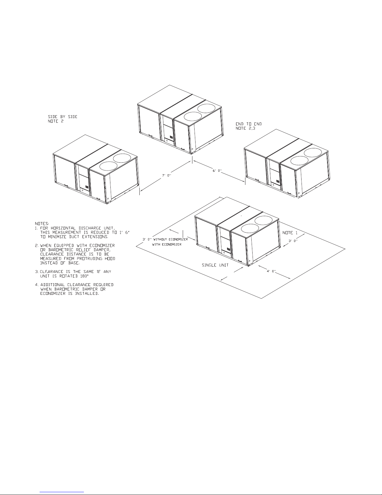
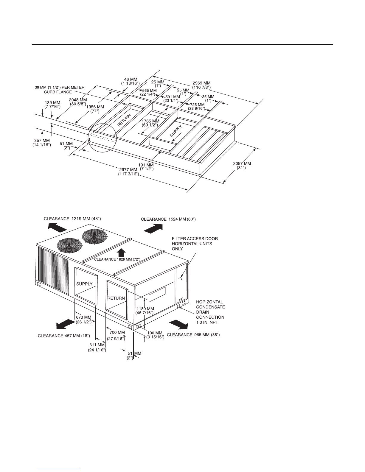
Unit Clearances
Figure 1, p. 12 illustrates the minimum operating and
service clearances for either a single or multiple unit
installation. These clearances are th e minimum distances
necessary to assure adequate serviceability, cataloged
unit capacity, an d peak operating efficiency.
Providing less than the recommended clearances may
result in condenser coil starvation, “short-circuiting” of
exhaust and economizer airflows, or recirculation of hot
condenser air.
• Avoid breathing fibergl as s dust.
• Use a NIOSH approved dust/mist respirator.
• Avoid contact with the skin or eyes. W ear long-sleeved,
loose-fitting clothing, gloves, and eye protection.
• Wash clothes separately from other clothing: rinse
washer thoroughly.
• Operations such as sawing, blowing, tear-out, and
spraying may generate fiber concentrations requiring
additional respiratory protection. Use the appropriate
NIOSH approved respiration in these situations.
RT-SVX26K-EN 11
Unit Dimensions
5' 8"
5' 0"
Figure 1. Typical installation clearance for single and multiple unit applications
12 RT-SVX26K-EN
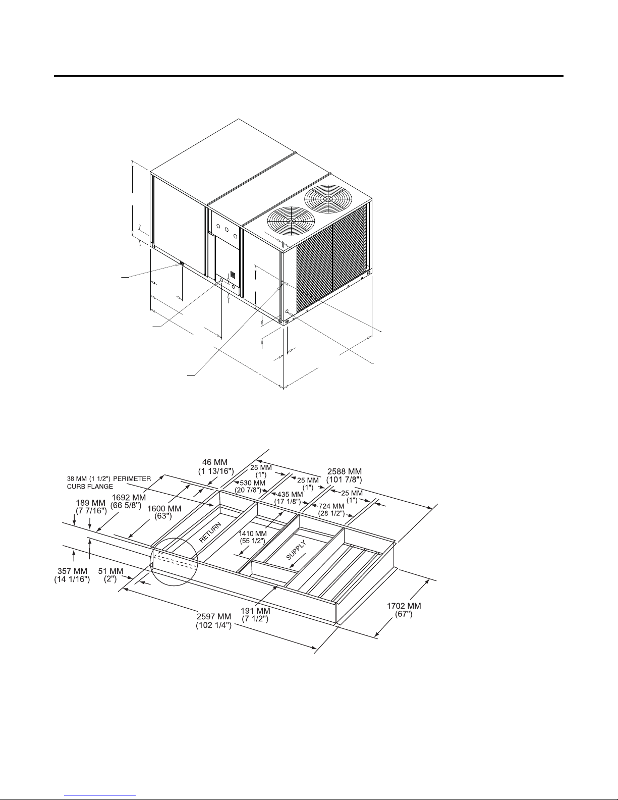
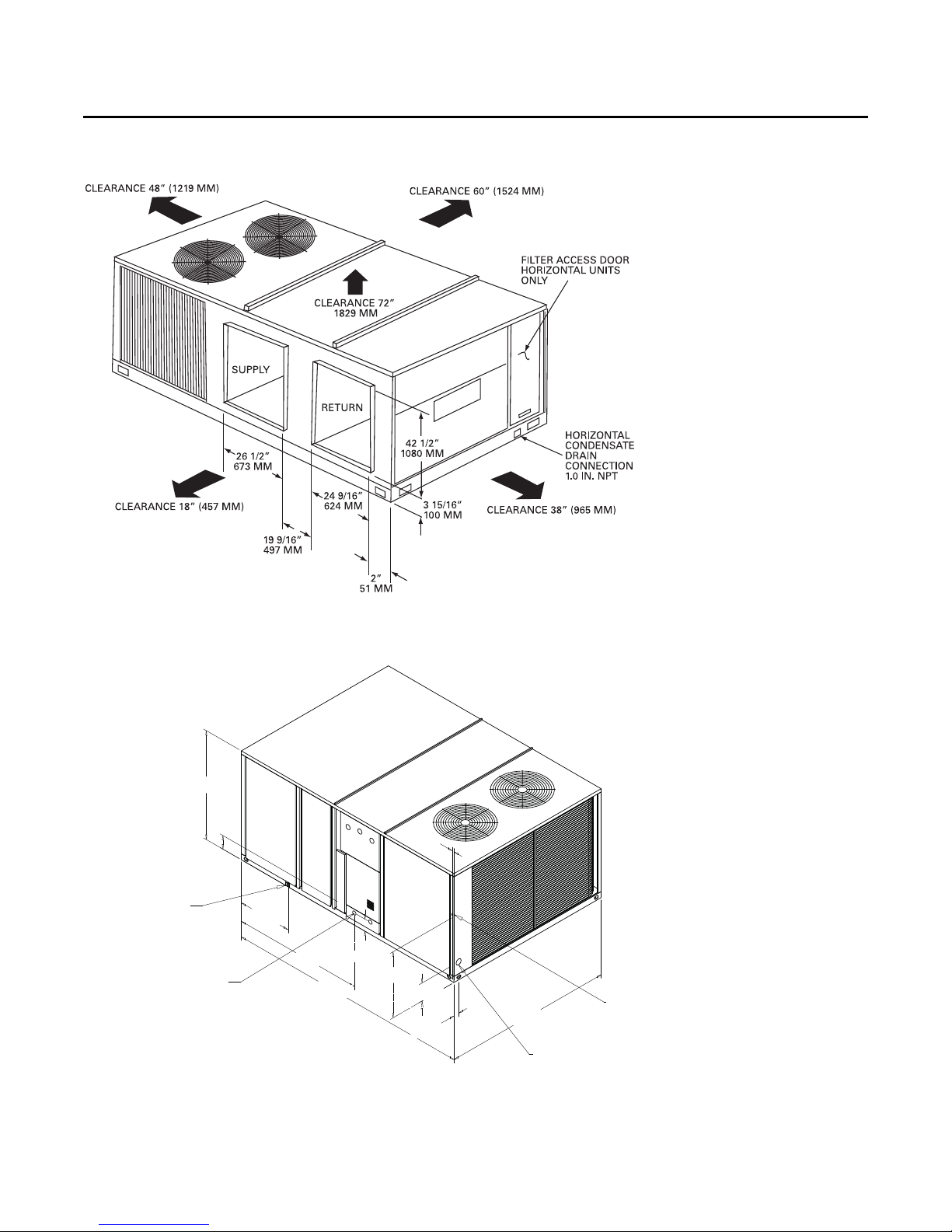
Figure 2. Unit dimensional data for 12½ tons standard efficiency units
2710 mm
(106 11/16”)
1273 mm
(50 1/8”)
168 mm
(6 5/8”)
651 mm
(25 5/8”)
1799 mm
(70 13/16”)
213 mm
(8 3/8”)
745 mm
(29 5/16”)
68 mm
(2 11/16”)
25 mm
(1”)
1453 mm
(57 3/16”)
152 mm
(6”)
(SEE NOTE)
22 mm (7/8”) DIA. HOLE
(UNIT CONTROL WIRE)
51 mm (2”) DIA. HOLE
(UNIT POWER WIRE)
DOWNFLOW CONDENSATE
DRAIN CONN 25 mm (1”) NPT
SERVICE GAUGE
PORT ACCESS
Unit Dimensions
Note: ½ NPT Gas Connection
Figure 3. Unit dimensional data for 12½ tons standard efficiency units
RT-SVX26K-EN 13
Unit Dimensions
3091 mm
(121 11/16”)
1372 mm
(54”)
173 mm
(6 13/16”)
679 mm
(26 3/4”)
2138 mm
(84 3/16”)
227 mm
(8 15/16”)
25 mm
(1”)
830 mm
(32 11/16”)
1643 mm
(64 11/16”)
151 mm
(5 15/16”)
22 mm (7/8”) DIA. HOLE
(UNIT CONTROL WI RE)
51 mm (2”) DIA. HOLE
(UNIT POWER WIRE)
DOWNFLOW CO NDENSATE
DRAIN CONN 25 mm (1”) NPT
(SEE NOTE)
68 mm
(2 11/16”)
Figure 4. Horizontal duct dimensional data 12½ tons standard efficiency units
Figure 5. Unit dimensional data 15–25 tons standard efficiency units
Note: ½ NPT Gas Connection
14 RT-SVX26K-EN
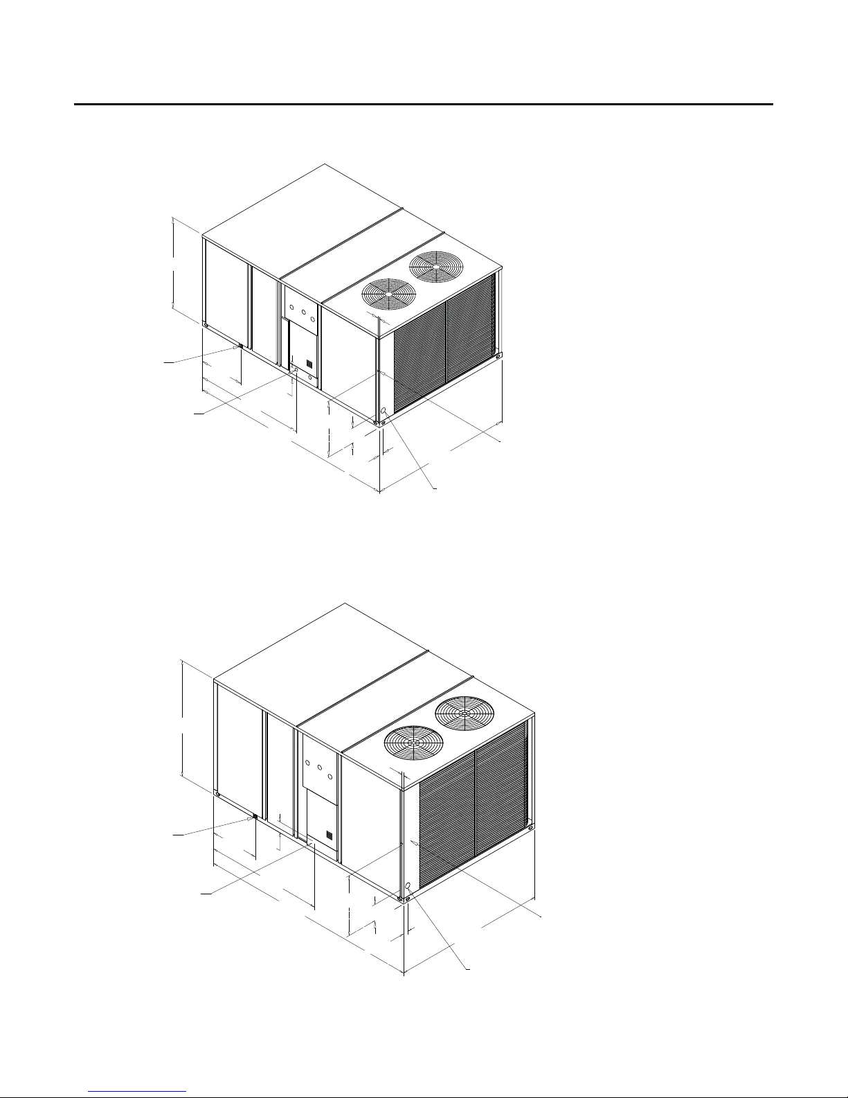
Figure 6. Unit dimensional data 12½ ton high efficiency units
1372 mm
(54”)
25 mm
(1”)
DOWNFLOW CONDENSATE
DRAIN CONN 25 mm (1”) NPT
GAS CONNECTION (SEE NOTE 1)
679 mm
(26 3/4”)
1643 mm
(64 11/16”)
(121 11/16”)
152 mm
(6”)
3091 mm
843 mm
(33 3/16”)
227 mm
(8 15/16”)
68 mm
(2 11/16”)
2138 mm
(84 3/16”)
76 mm (3”) DIA. HOLE
(UNIT POWER W IRE)
22 mm (7/8”) DIA. HOLE
(UNIT CONTROL WIRE)
Unit Dimensions
Note: ½ NPT Gas Connection
Figure 7. Unit dimensional data 15–25 tons high efficiency units
1629 mm
(64 1/8”)
25 mm
(1”)
DOWNFLOW CO NDENSATE
DRAIN CONN 25 mm (1”) NPT
GAS CONNECTION (SEE NOTE 1)
679 mm
(26 3/4”)
152 mm
(6”)
1643 mm
(64 11/16”)
(121 11/16”)
3091 mm
843 mm
(33 3/16”)
227 mm
(8 15/16”)
68 mm
(2 11/16”)
(84 3/16”)
2138 mm
76 mm (3”) DIA. HOLE
(UNIT POWER WIRE)
22 mm (7/8”) DIA. HOLE
(UNIT CONTROL WIRE)
Note: ½ NPT Gas Connection
RT-SVX26K-EN 15
Unit Dimensions
Figure 8. Unit dimensional data 15–25 tons standard efficiency units, 12½–25 tons high efficiency units
Figure 9. Horizontal duct dimensional data 15–25 tons standard efficiency units, 12½–25 tons high efficiency units
16 RT-SVX26K-EN
 Loading...