

Page 1
TL-SG3216/TL-SG3424
JetStream L2 Lite Managed Switch
Rev: 1.0.2
1910010511
Page 2

COPYRIGHT & TRADEMARKS
Specifications are subject to change without notice. is a registered trademark of
TP-LINK TECHNOLOGIES CO., LTD. Other brands and product names are trademarks or
registered trademarks of their respective holders.
No part of the specifications may be reproduced in any form or by any means or used to make any
derivative such as translation, transformation, or adaptation without permission from TP-LINK
TECHNOLOGIES CO., LTD. Copyright © 2011 TP-LINK TECHNOLOGIES CO., LTD. All rights
reserved.
http://www.tp-link.com
I
Page 3

CONTENTS
Preface .............................................................................................................. 1
Chapter 1 Using the CLI ....................................................................................... 4
1.1 Accessing the CLI ...........................................................................................................4
1.1.1 Logon by a console port .......................................................................................4
1.1.2 Logon by Telnet ....................................................................................................6
1.2 CLI Command Modes .....................................................................................................8
1.3 Security Levels .............................................................................................................10
1.4 Conventions.................................................................................................................. 11
1.4.1 Format Conventions ........................................................................................... 11
1.4.2 Special Characters.............................................................................................. 11
1.4.3 Parameter Format............................................................................................... 11
Chapter 2 User Interface .................................................................................... 12
enable....................................................................................................................................12
enable password ...................................................................................................................12
disable ...................................................................................................................................13
configure................................................................................................................................13
exit.........................................................................................................................................13
end ........................................................................................................................................14
Chapter 3 IEEE 802.1Q VLAN Commands ........................................................ 15
vlan database ........................................................................................................................15
vlan........................................................................................................................................15
interface vlan .........................................................................................................................16
description .............................................................................................................................16
switchport type ......................................................................................................................17
switchport allowed vlan..........................................................................................................17
switchport pvid.......................................................................................................................18
switchport general egress-rule ..............................................................................................18
show vlan ..............................................................................................................................19
show interface switchport ...................................................................................................... 19
Chapter 4 MAC VLAN Commands ..................................................................... 20
mac-vlan add.........................................................................................................................20
mac-vlan remove...................................................................................................................20
mac-vlan modify ....................................................................................................................21
II
Page 4

show mac-vlan ......................................................................................................................21
Chapter 5 Protocol VLAN Commands............................................................... 22
protocol-vlan template ........................................................................................................... 22
protocol-vlan vlan ..................................................................................................................22
show protocol-vlan template..................................................................................................23
show protocol-vlan vlan .........................................................................................................23
Chapter 6 Voice VLAN Commands.................................................................... 25
voice-vlan enable ..................................................................................................................25
voice-vlan aging-time ............................................................................................................25
voice-vlan priority ..................................................................................................................26
voice-vlan oui ........................................................................................................................26
switchport voice-vlan mode ...................................................................................................27
switchport voice-vlan security................................................................................................28
show voice-vlan global ..........................................................................................................28
show voice-vlan oui ...............................................................................................................28
show voice-vlan switchport....................................................................................................29
Chapter 7 GVRP Commands.............................................................................. 30
gvrp .......................................................................................................................................30
gvrp (interface) ......................................................................................................................30
gvrp registration.....................................................................................................................31
gvrp timer ..............................................................................................................................31
show gvrp global ...................................................................................................................32
show gvrp interface ...............................................................................................................33
Chapter 8 LAG Commands ................................................................................ 34
interface link-aggregation ......................................................................................................34
interface range link-aggregation ............................................................................................34
link-aggregation.....................................................................................................................35
link-aggregation hash-algorithm ............................................................................................36
description .............................................................................................................................36
show interfaces link-aggregation ...........................................................................................37
Chapter 9 LACP Commands .............................................................................. 38
lacp........................................................................................................................................38
lacp (interface).......................................................................................................................38
lacp admin-key ......................................................................................................................39
III
Page 5

lacp system-priority ...............................................................................................................39
lacp port-priority.....................................................................................................................40
show lacp ..............................................................................................................................40
show lacp interface................................................................................................................41
Chapter 10 User Manage Commands.................................................................. 42
user add ................................................................................................................................42
user remove ..........................................................................................................................43
user modify status .................................................................................................................43
user modify type ....................................................................................................................44
user modify password............................................................................................................44
user access-control disable ...................................................................................................45
user access-control ip-based.................................................................................................45
user access-control mac-based.............................................................................................46
user access-control port-based .............................................................................................46
user max-number ..................................................................................................................47
user idle-timeout....................................................................................................................47
show user account-list...........................................................................................................48
show user configuration.........................................................................................................48
Chapter 11 Binding Table Commands................................................................. 50
binding-table user-bind ..........................................................................................................50
binding-table remove .............................................................................................................51
dhcp-snooping.......................................................................................................................51
dhcp-snooping global ............................................................................................................52
dhcp-snooping information enable ........................................................................................53
dhcp-snooping information strategy ......................................................................................53
dhcp-snooping information user-defined ...............................................................................54
dhcp-snooping information remote-id .................................................................................... 54
dhcp-snooping information circuit-id......................................................................................55
dhcp-snooping trusted ...........................................................................................................55
dhcp-snooping mac-verify .....................................................................................................56
dhcp-snooping rate-limit ........................................................................................................ 56
dhcp-snooping decline...........................................................................................................57
show binding-table.................................................................................................................57
show dhcp-snooping global ...................................................................................................58
show dhcp-snooping information...........................................................................................58
show dhcp-snooping interface...............................................................................................59
IV
Page 6

Chapter 12 ARP Inspection Commands.............................................................. 60
arp detection (global)............................................................................................................. 60
arp detection trust-port ..........................................................................................................60
arp detection (interface).........................................................................................................61
arp detection limit-rate...........................................................................................................61
arp detection recover............................................................................................................. 62
show arp detection global......................................................................................................63
show arp detection interface..................................................................................................63
show arp detection statistic ...................................................................................................63
show arp detection statistic reset ..........................................................................................64
Chapter 13 DoS Defend Command...................................................................... 65
dos-prevent ...........................................................................................................................65
dos-prevent type.................................................................................................................... 65
show dos-prevent ..................................................................................................................66
Chapter 14 IEEE 802.1X Commands ................................................................... 67
dot1x......................................................................................................................................67
dot1x authentication-method .................................................................................................67
dot1x guest-vlan ....................................................................................................................68
dot1x quiet-period.................................................................................................................. 69
dot1x timer.............................................................................................................................69
dot1x retry .............................................................................................................................70
dot1x(interface) .....................................................................................................................70
dot1x guest-vlan ....................................................................................................................71
dot1x port-control ..................................................................................................................71
dot1x port-method .................................................................................................................72
radius authentication primary-ip ............................................................................................73
radius authentication secondary-ip ........................................................................................73
radius authentication port ...................................................................................................... 74
radius authentication key.......................................................................................................74
radius accounting enable.......................................................................................................75
radius accounting primary-ip .................................................................................................76
radius accounting secondary-ip.............................................................................................76
radius accounting port ........................................................................................................... 77
radius accounting key............................................................................................................ 77
radius response-timeout ........................................................................................................78
show dot1x global.................................................................................................................. 78
V
Page 7

show dot1x interface .............................................................................................................79
show radius authentication ....................................................................................................79
show radius accounting.........................................................................................................80
Chapter 15 Log Commands ................................................................................. 81
logging local buffer ................................................................................................................81
logging local flash..................................................................................................................81
logging clear ..........................................................................................................................82
logging loghost ......................................................................................................................83
show logging local-config ......................................................................................................83
show logging loghost.............................................................................................................84
show logging buffer level .......................................................................................................84
show logging flash level.........................................................................................................85
Chapter 16 SSH Commands................................................................................. 86
ssh server enable ..................................................................................................................86
ssh version ............................................................................................................................ 86
ssh idle-timeout .....................................................................................................................87
ssh max-client .......................................................................................................................87
ssh download ........................................................................................................................88
show ssh ...............................................................................................................................88
Chapter 17 SSL Commands ................................................................................. 89
ssl enable .............................................................................................................................. 89
ssl download certificate .........................................................................................................89
ssl download key ...................................................................................................................90
show ssl.................................................................................................................................90
Chapter 18 Address Commands.......................................................................... 92
bridge address port-security ..................................................................................................92
bridge address static .............................................................................................................93
bridge aging-time................................................................................................................... 93
bridge address filtering .......................................................................................................... 94
show bridge port-security ......................................................................................................95
show bridge address .............................................................................................................95
show bridge aging-time .........................................................................................................96
Chapter 19 System Commands ........................................................................... 97
system-descript .....................................................................................................................97
VI
Page 8

system-time gmt ....................................................................................................................97
system-time manual ..............................................................................................................98
ip address..............................................................................................................................98
ip dhcp-alloc ..........................................................................................................................99
ip bootp-alloc .........................................................................................................................99
reset ....................................................................................................................................100
reboot ..................................................................................................................................100
user-config backup ..............................................................................................................101
user-config load...................................................................................................................101
user-config save ..................................................................................................................102
firmware upgrade ................................................................................................................102
ping .....................................................................................................................................103
tracert ..................................................................................................................................103
loopback ..............................................................................................................................104
show system-info................................................................................................................. 104
show ip address ..................................................................................................................105
Chapter 20 Ethernet Configuration Commands ................................................106
interface ethernet ................................................................................................................106
interface range ethernet ......................................................................................................106
description ...........................................................................................................................107
shutdown .............................................................................................................................107
flow-control ..........................................................................................................................108
negotiation...........................................................................................................................108
storm-control .......................................................................................................................109
storm-control disable bc-rate ............................................................................................... 110
storm-control disable mc-rate .............................................................................................. 110
storm-control disable ul-rate ................................................................................................ 111
port rate-limit ....................................................................................................................... 111
port rate-limit disable ingress............................................................................................... 112
port rate-limit disable egress ............................................................................................... 112
show interface configuration................................................................................................112
show interface status........................................................................................................... 113
show interface counters....................................................................................................... 113
show storm-control ethernet ................................................................................................ 114
show port rate-limit .............................................................................................................. 114
Chapter 21 QoS Commands................................................................................116
VII
Page 9

qos ...................................................................................................................................... 116
qos dot1p config .................................................................................................................. 116
qos dscp enable .................................................................................................................. 117
qos dscp config ...................................................................................................................118
qos scheduler ...................................................................................................................... 119
show qos port-based ........................................................................................................... 120
show qos dot1p ...................................................................................................................120
show qos dscp.....................................................................................................................120
show qos scheduler............................................................................................................. 121
Chapter 22 Port Mirror Commands ....................................................................122
mirror add ............................................................................................................................122
mirror remove group............................................................................................................123
mirror remove mirrored........................................................................................................123
show mirror..........................................................................................................................124
Chapter 23 ACL Commands................................................................................125
acl time-segment .................................................................................................................125
acl holiday ...........................................................................................................................126
acl create.............................................................................................................................126
acl rule mac-acl ...................................................................................................................127
acl rule std-acl .....................................................................................................................128
acl policy policy-add ............................................................................................................129
acl policy action-add............................................................................................................130
acl bind to-port..................................................................................................................... 131
acl bind to-vlan ....................................................................................................................131
show acl time-segment........................................................................................................132
show acl holiday ..................................................................................................................132
show acl config....................................................................................................................133
show acl bind.......................................................................................................................133
Chapter 24 MSTP Commands.............................................................................134
spanning-tree global............................................................................................................134
spanning-tree common-config .............................................................................................135
spanning-tree region............................................................................................................136
spanning-tree msti...............................................................................................................137
spanning-tree msti...............................................................................................................138
spanning-tree tc-defend.......................................................................................................138
spanning-tree security .........................................................................................................139
VIII
Page 10

spanning-tree mcheck ......................................................................................................... 140
show spanning-tree global-info............................................................................................ 140
show spanning-tree global-config........................................................................................141
show spanning-tree port-config ...........................................................................................141
show spanning-tree region ..................................................................................................142
show spanning-tree msti config ...........................................................................................142
show spanning-tree msti port ..............................................................................................142
show spanning-tree security tc-defend................................................................................143
show spanning-tree security port-defend.............................................................................143
Chapter 25 IGMP Commands..............................................................................145
igmp-snooping global ..........................................................................................................145
igmp-snooping config ..........................................................................................................145
igmp-snooping vlan-config-add ...........................................................................................146
igmp-snooping vlan-config...................................................................................................147
igmp-snooping multi-vlan-config..........................................................................................148
igmp-snooping static-entry-add ...........................................................................................149
igmp-snooping filter-add ......................................................................................................150
igmp-snooping filter-config ..................................................................................................150
igmp-snooping filter ............................................................................................................. 151
show igmp-snooping global-config ......................................................................................152
show igmp-snooping port-config.......................................................................................... 152
show igmp-snooping vlan-config .........................................................................................153
show igmp-snooping multi-vlan ...........................................................................................153
show igmp-snooping multi-ip-list .........................................................................................153
show igmp-snooping filter-ip-addr .......................................................................................154
show igmp-snooping port-filter ............................................................................................154
show igmp-snooping packet-stat .........................................................................................155
show igmp-snooping packet-stat-clear ................................................................................ 155
Chapter 26 SNMP Commands.............................................................................156
snmp global .........................................................................................................................156
snmp view-add ....................................................................................................................157
snmp group-add ..................................................................................................................157
snmp user-add ....................................................................................................................159
snmp community-add .......................................................................................................... 160
snmp notify-add...................................................................................................................161
snmp-rmon history sample-cfg ............................................................................................162
IX
Page 11

snmp-rmon history owner ....................................................................................................163
snmp-rmon history enable ...................................................................................................163
snmp-rmon event user.........................................................................................................164
snmp-rmon event description ..............................................................................................164
snmp-rmon event type.........................................................................................................165
snmp-rmon event owner......................................................................................................166
snmp-rmon event enable.....................................................................................................166
snmp-rmon alarm config......................................................................................................167
snmp-rmon alarm owner......................................................................................................168
snmp-rmon alarm enable.....................................................................................................169
show snmp global-config .....................................................................................................169
show snmp view ..................................................................................................................170
show snmp group ................................................................................................................170
show snmp user ..................................................................................................................170
show snmp community........................................................................................................171
show snmp destination-host ................................................................................................171
show snmp-rmon history .....................................................................................................171
show snmp-rmon event ....................................................................................................... 172
show snmp-rmon alarm .......................................................................................................172
Chapter 27 Cluster Commands...........................................................................174
cluster ndp...........................................................................................................................174
cluster ntdp..........................................................................................................................175
cluster explore .....................................................................................................................176
cluster..................................................................................................................................176
cluster manage role-change ................................................................................................177
show cluster ndp global .......................................................................................................177
show cluster ndp port-status................................................................................................178
show cluster neighbour........................................................................................................178
show cluster ntdp global ......................................................................................................178
show cluster ntdp port-status...............................................................................................179
show cluster ntdp device ..................................................................................................... 179
show cluster manage role....................................................................................................180
X
Page 12

Preface
This Guide is intended for network administrator to provide referenced information about CLI
(Command Line Interface). The device mentioned in this Guide stands for TL-SG3216/TL-SG3424
JetStream L2 Lite Managed Switch.
Overview of this Guide
Chapter 1: Using the CLI
Provide information about how to use the CLI, CLI Command Modes, Security Levels and some
Conventions.
Chapter 2: User Interface
Provide information about the commands used to switch between five CLI Command Modes.
Chapter 3: IEEE 802.1Q VLAN Commands
Provide information about the commands used for configuring IEEE 802.1Q VLAN.
Chapter 4: MAC VLAN Commands
Provide information about the commands used for configuring MAC-Based VLAN.
Chapter 5: Protocol VLAN Commands
Provide information about the commands used for configuring Protocol VLAN.
Chapter 6: Voice VLAN Commands
Provide information about the commands used for configuring Voice VLAN.
Chapter 7: GVRP Commands
Provide information about the commands used for configuring GVRP (GARP VLAN registration
protocol).
Chapter 8: LAG Commands
Provide information about the commands used for configuring LAG (Link Aggregation Group).
Chapter 9: LACP Commands
Provide information about the commands used for configuring LACP (Link Aggregation Control
Protocol).
Chapter 10: User Manage Commands
Provide information about the commands used for user management.
Chapter 11: Binding Table Commands
Provide information about the commands used for binding the IP address, MAC address, VLAN
and the connected Port number of the Host together.
Chapter 12: ARP Inspection Commands
1
Page 13

Provide information about the commands used for protecting the switch from the ARP cheating or
ARP Attack.
Chapter 13: DoS Defend Command
Provide information about the commands used for DoS defend and detecting the DoS attack.
Chapter 14: IEEE 802.1X Commands
Provide information about the commands used for configuring IEEE 802.1X function.
Chapter 15: Log Commands
Provide information about the commands used for configuring system log.
Chapter 16: SSH Commands
Provide information about the commands used for configuring and managing SSH (Security
Shell).
Chapter 17: SSL Commands
Provide information about the commands used for configuring and managing SSL (Secure
Sockets Layer).
Chapter 18: Address Commands
Provide information about the commands used for Address configuration.
Chapter 19: System Commands
Provide information about the commands used for configuring the System information and System
IP, reboot and reset the switch, upgrade the switch system and other operations.
Chapter 20: Ethernet Configuration Commands
Provide information about the commands used for configuring the Bandwidth Control, Negotiation
Mode, and Storm Control for enthernet ports.
Chapter 21: QoS Commands
Provide information about the commands used for configuring the QoS function.
Chapter 22: Port Mirror Commands
Provide information about the commands used for configuring the Port Mirror function.
Chapter 23: ACL Commands
Provide information about the commands used for configuring the ACL (Access Control List).
Chapter 24: MSTP Commands
Provide information about the commands used for configuring the MSTP (Multiple Spanning Tree
Protocol).
Chapter 25: IGMP Commands
Provide information about the commands used for configuring the IGMP Snooping (Internet Group
Management Protocol Snooping).
Chapter 26: SNMP Commands
2
Page 14

Provide information about the commands used for configuring the SNMP (Simple Network
Management Protocol) functions.
Chapter 27 Cluster Commands
Provide information about the commands used for configuring the Cluster Management function.
3
Page 15
Chapter 1 Using the CLI
1.1 Accessing the CLI
You can log on to the switch and access the CLI by the following two methods:
1. Log on to the switch by the console port on the switch.
2. Log on to the switch remotely by a Telnet or SSH connection through an Ethernet port.
1.1.1 Logon by a console port
To log on to the switch by the console port on the switch, please take the following steps:
1. Connect the PCs or Terminals to the console port on the switch by a provided cable.
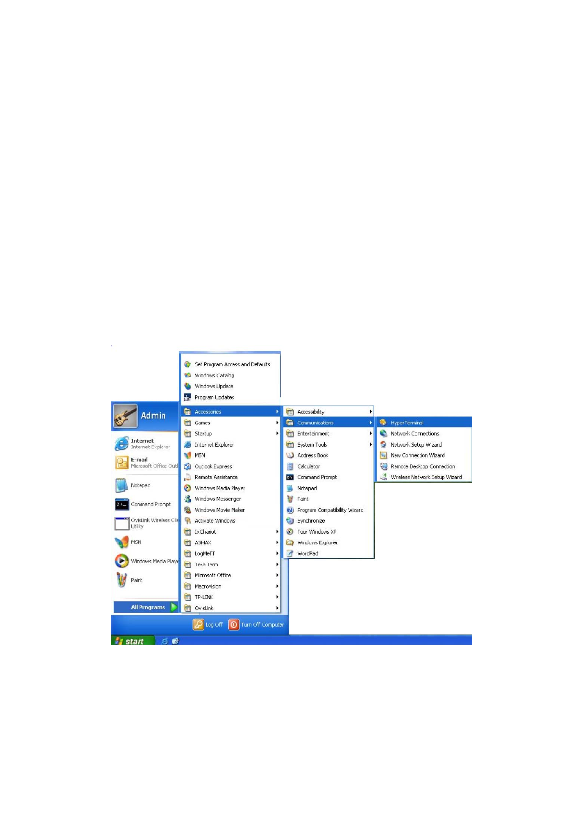
2. Click Start →
open the Hyper Terminal as the figure 1-1 shown.
All Programs → Accessories→ Communications → Hyper Terminal to
Figure 1-1 Open
3. The Connection Description Window will prompt as figure1-2. Enter a name into the
Name field and click OK.
Hyper Terminal
4
Page 16
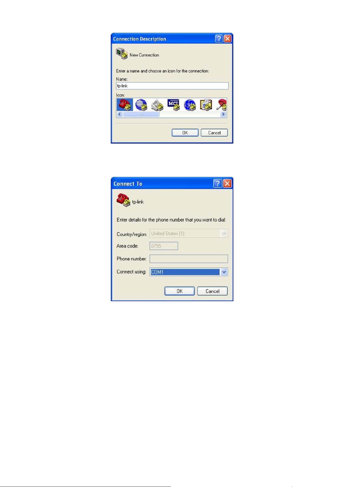
Figure 1-2 Connection Description
4. Select the port to connect in figure 1-3, and click OK.
Figure 1-3 Select the port to connect
5. Configure the port selected in the step above as the following figure1-4 shown. Configure
Bits per second as 38400, Data bits as 8, Parity as None, Stop bits as 1, Flow control
as None, and then click OK.
5
Page 17
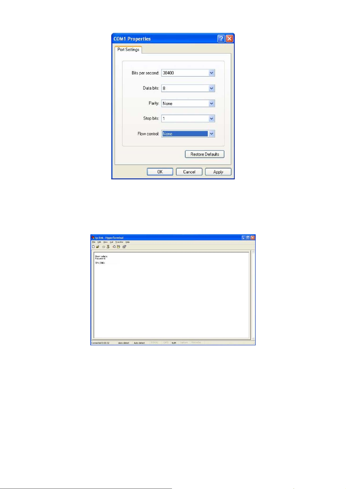
Figure 1-4 Port Settings
6. Type the User name and Password in the Hyper Terminal window, the factory default
value for both of them is admin. The DOS prompt” TP-LINK>” will appear after pressing
the Enter button as figure1-5 shown. It indicates that you can use the CLI now.
Figure 1-5 Log in the Switch
1.1.2 Logon by Telnet
To log on to the switch by a Telnet connection, please take the following steps:
1. Make sure the switch and the PC are in the same LAN.
2. Click Start → Run to open the Run window.
6
Page 18
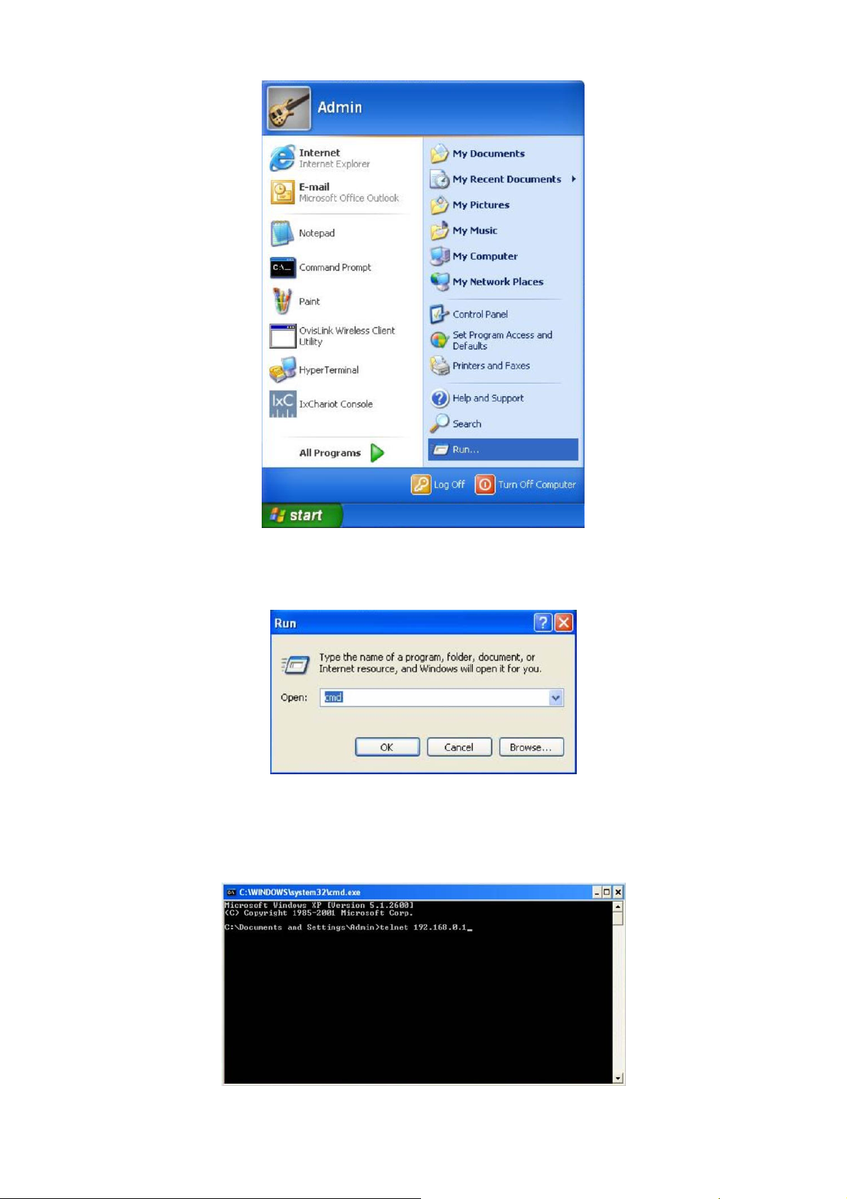
Figure 1-6 Open the Run window
3. Type cmd in the prompt Run window as figure 1-7 and click OK.
Figure 1-7 Run Window
4. Type telnet 192.168.0.1 in the command prompt shown as figure1-8, and press the Enter
button.
Figure 1-8 Connecting to the Switch
7
Page 19
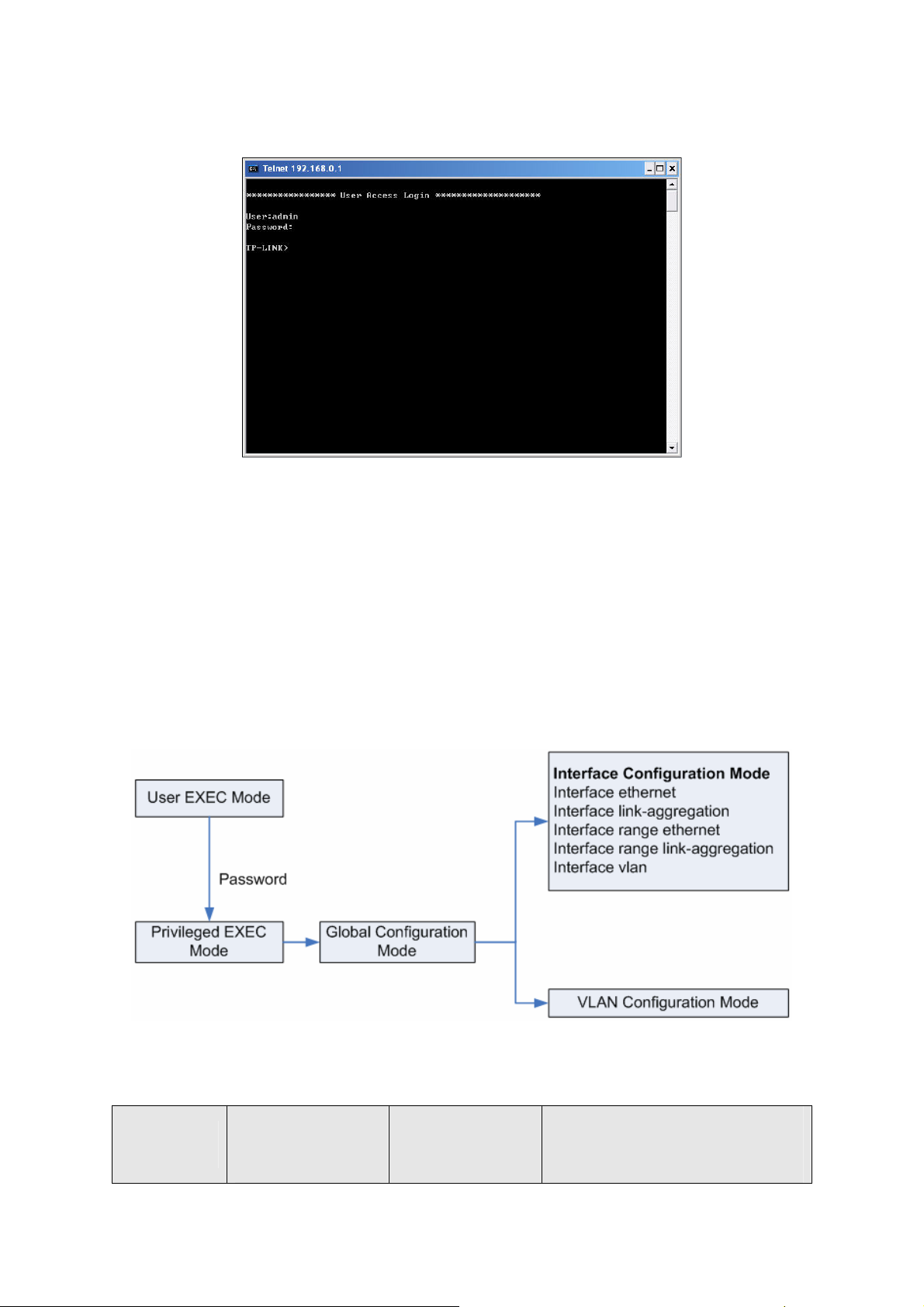
5. Type the User name and Password (the factory default value for both of them is admin) and
press the Enter button, then you can use the CLI now, which is shown as figure1-9.
Figure 1-9 Log in the Switch
1.2 CLI Command Modes
The CLI is divided into different command modes: User EXEC Mode, Privileged EXEC Mode,
Global Configuration Mode, Interface Configuration Mode and VLAN Database (VLAN
Configuration Mode). Interface Configuration Mode can also be divided into Interface Ethernet,
Interface link-aggregation and some other modes, which is shown as the following diagram.
The following table gives detailed information about the Accessing path, Prompt of each mode and
how to exit the current mode and access the next mode.
Mode
Accessing
Prompt
Path
8
Logout or Access the next
mode
Page 20

User EXEC
Mode
Privileged
EXEC Mode
Global
Configuration
Mode
Primary mode once it is
connected with the
switch.
Use the enable
command to enter this
mode from User EXEC
mode.
Use the configure
command to enter this
mode from Privileged
EXEC mode.
TP-LINK>
TP-LINK#
TP-LINK(config)#
Use the exit command to disconnect the
switch (except that the switch is
connected through the Console port).
Use the enable command to access
Privileged EXEC mode.
Use the exit command to disconnect the
switch (except that the switch is
connected through the Console port).
Enter the disable command to return to
User EXEC mode.
Enter configure command to access
Global Configuration mode.
Use the exit or the end command or
press Ctrl+Z to return to Privileged
EXEC mode.
Use the interface type number
command to access interface
Configuration mode.
Use the vlan database to access VLAN
Configuration mode.
Interface
Configuration
Mode
Use the interface type
number command to
enter this mode from
Global Configuration
mode.
Use the vlan database
TP-LINK(config-if
)#
Use the end command or press Ctrl+Z
to return to Privileged EXEC mode.
Enter exit command to return to Global
Configuration mode.
A port number must be specified in the
interface command.
Use the end command or press Ctrl+Z
VLAN
command to enter this
TP-LINK(config-
to return to Privileged EXEC mode.
Configuration
Mode
mode from Global
Configuration mode.
vlan)#
Enter the exit command to return to
Global configuration mode.
Note:
1. The user is automatically in User EXEC Mode after the connection between the PC and the
switch is established by a console port or by a telnet connection.
2. Each command mode has its own set of specific commands. To configure some commands,
9
Page 21

you should access the corresponding command mode firstly.
z Global Configuration Mode: In this mode, global commands are provided, such as the
Spanning Tree, Schedule Mode and so on.
z Interface Configuration Mode: In this mode, users can configure one or several ports,
different ports corresponds to different commands
a). Interface Ethernet: Configure parameters for an Ethernet port, such as Duplex-mode,
flow control status.
b). Interface range Ethernet: The commands contained are the same as that of the
Interface Ethernet. Configure parameters for several Ethernet ports.
c). Interface link-aggregation: Configure parameters for a link-aggregation, such as
broadcast storm.
d). Interface range link-aggregation: Configure parameters for multi-trunks.
e). Interface vlan: Configure parameters for the vlan-port.
z Vlan Configuration Mode: In this mode, users can create a VLAN and add a specified
port to the VLAN.
3. Some commands are global, that means they can be performed in all modes:
z show: display all information of switch, for example: statistic information, port information,
VLAN information.
z history: Display the commands history.
1.3 Security Levels
This switch’s security is divided into two levels: User level and Admin level.
User level only allows users to do some simple operations in User EXEC Mode; Admin level
allows you to monitor, configure and manage the switch in Privileged EXEC Mode, Global
Configuration Mode, Interface Configuration Mode and VLAN Configuration Mode.
Users get the privilege to the User level once connecting console port with the switch or logging in
by Telnet. However, Guest users are restricted to access the CLI..
Users can enter Privileged EXEC mode from User EXEC mode by using the enable command. In
default case, no password is needed. In Global Configuration Mode, you can configure password
for Admin level by enable password command. Once password is configured, you are required to
enter it to access Privileged EXEC mode.
10
Page 22

1.4 Conventions
1.4.1 Format Conventions
The following conventions are used in this Guide:
¾ Items in square brackets [ ] are optional
¾ Items in braces { } are required
¾ Alternative items are grouped in braces and separated by vertical bars. For example: speed
{10 | 100 | 1000 }
¾ Bold indicates an unalterable keyword. For example: show logging
¾ Normal Font indicates a constant (several options are enumerated and only one can be
selected). For example: switchport type { access | trunk | general }
¾ Italic Font indicates a variable (an actual value must be assigned). For example: bridge
aging-time aging-time
1.4.2 Special Characters
You should pay attentions to the describtion below if the variable is a character string:
¾ These six characters ” < > , \ & can not be input.
¾ If a blank is contained in a character string, single or double quotation marks should be used,
for example ’hello world’, ”hello world”, and the words in the quotation marks will be identified
as a string. Otherwise, the words will be identified as several strings.
1.4.3 Parameter Format
Some parameters must be entered in special formats which are shown as follows:
¾ MAC Address must be enter in the format of xx:xx:xx:xx:xx:xx
¾ One or several values can be typed for a port-list or a vlan-list using comma to separate. Use
a hyphen to designate a range of values, for instance, 1,3-5,7 indicates choosing 1,3,4,5,7.
11
Page 23

Chapter 2 User Interface
enable
Description
The enable command is used to access Privileged EXEC Mode from User
EXEC Mode.
Syntax
enable
Command Mode
User EXEC Mode
Example
If you have set the password to access Privileged EXEC Mode from User EXEC
Mode:
TP-LINK>enable
Enter password:
TP-LINK#
enable password
Description
The enable password command is used to set the password for users to
access Privileged EXEC Mode from User EXEC Mode. To return to the default
configuration, please use no enable password command.
Syntax
enable password password
no enable password
Parameter
password —— super password , which contains 16 characters at most,
composing digits, English letters and underdashes only. By default, it is empty.
Command Mode
Global Configuration Mode
Example
Set the super password as admin to access Privileged EXEC Mode from User
EXEC Mode:
TP-LINK(config)# enable password admin
12
Page 24

disable
Description
Syntax
Command Mode
Example
The disable command is used to return to User EXEC Mode from Privileged
EXEC Mode.
disable
Privileged EXEC Mode
Return to User EXEC Mode from Privileged EXEC Mode:
TP-LINK# disable
TP-LINK>
configure
Description
Syntax
Command Mode
Example
The configure command is used to access Global Configuration Mode from
Privileged EXEC Mode.
configure
Privileged EXEC Mode
Access Global Configuration Mode from Privileged EXEC Mode:
TP-LINK# configure
TP-LINK(config)#
exit
Description
The exit command is used to return to the previous Mode from the current
Mode.
Syntax
exit
13
Page 25

end
Command Mode
Any Configuration Mode
Example
Return to Global Configuration Mode from Interface Configuration Mode,and
then return to Privileged EXEC Mode:
TP-LINK(config-if)# exit
TP-LINK(config)#exit
TP-LINK#
Description
The end command is used to return to Privileged EXEC Mode.
Syntax
end
Command Mode
Any Configuration Mode
Example
Return to Privileged EXEC Mode from Interface Configuration Mode:
TP-LINK(config-if)#end
TP-LINK#
14
Page 26

Chapter 3 IEEE 802.1Q VLAN Commands
VLAN (Virtual Local Area Network) technology is developed for the switch to divide the LAN into
multiple logical LANs flexibly. Hosts in the same VLAN can communicate with each other,
regardless of their physical locations. VLAN can enhance performance by conserving bandwidth,
and improve security by limiting traffic to specific domains.
vlan database
Description
The vlan database command is used to access VLAN Configuration Mode for
creating, deleting 802.1Q VLAN and other operations.
Syntax
vlan database
vlan
Command Mode
Global Configuration Mode
Example
Access VLAN Configuration Mode:
TP-LINK(config)# vlan database
TP-LINK(config-vlan)#
Description
The vlan command is used to creat IEEE 802.1Q VLAN. To delete the IEEE
802.1Q VLAN, please use no vlan command.
Syntax
vlan vlan-id
no vlan vlan-id
Parameter
vlan-id ——VLAN ID, ranging from 2 to 4094.
Command Mode
VLAN Configuration Mode
Example
15
Page 27

Create a VLAN, the vid of which is 12:
TP-LINK(config)# vlan database
TP-LINK(config-vlan)#vlan 12
interface vlan
Description
The interface vlan command is used to access VLAN Interface Mode to
configure the specified VLAN.
Syntax
interface vlan vlan-id
Parameter
vlan-id ——VLAN ID,ranging from 1 to 4094.
Command Mode
Global Configuration Mode
Example
Configure the VLAN2:
TP-LINK(config)# interface vlan 2
description
Description
The description command is used to assign a description string to a VLAN. To
clear the description, please use no description command.
Syntax
description descript
no descriotion
Parameter
descript ——String to describe the VLAN, which contains 16 characters at most.
Command Mode
Interface Configuration Mode(interface vlan)
Example
Specify the description string of the VLAN 2 as “vlan 2”:
TP-LINK(config)# interface vlan 2
16
Page 28

TP-LINK(config-if)#description vlan2
switchport type
Description
The switchport type command is used to configure the Link Types for the
ports.
Syntax
switchport type { access | trunk | general }
Parameter
access | trunk | general —— Link Types. There are three Link Types for the
ports.
Command Mode
Interface Configuration Mode ( interface ethernet / interface range ethernet )
Example
Specify the Link Type of port 5 as general:
TP-LINK(config)# interface ethernet 5
TP-LINK(config-if)#switchport type general
switchport allowed vlan
Description
The switchport allowed vlan command is used to add the desired port to IEEE
802.1Q VLAN,or to remove a port from the correspounding VLAN.
Syntax
switchport allowed vlan add vlan-list
switchport allowed vlan remove vlan-list
Parameter
vlan-list —— VLAN ID list, it is multi-optional.
Command Mode
Interface Configuration Mode ( interface ethernet / interface range ethernet )
Example
Add port 2 to IEEE 802.1Q VLAN:
TP-LINK(config)# interface ethernet 2
17
Page 29

TP-LINK(config-if)# switchport allowed vlan add 2
switchport pvid
Description
The switchport pvid command is used to configure the PVID for the switch
ports.
Syntax
switchport pvid vlan-id
Parameter
vlan-id —— VLAN ID, ranging from 1 to 4094.
Command Mode
Interface Configuration Mode (interface ethernet / interface range ethernet )
Example
Specify the PVID of port 2 as 2:
TP-LINK(config)# interface ethernet 2
TP-LINK(config-if)# switchport pvid 2
switchport general egress-rule
Description
The switchport general egress-rule command is used to configure the
egress-rule of the general port.
Syntax
switchport general egress-rule [vlan-id]{ untagged | tagged }
Parameter
vlan-id —— VLAN ID, ranging from 1 to 4094. By default , display all the
information of IEEE 802.1Q VLAN.
untagged | tagged ——egress-rule,untagged or tagged
Command Mode
Interface Configuration Mode ( interface ethernet / interface range ethernet )
Example
Specify the egress-rule of port 2 in vlan 3as tagged:
TP-LINK(config)# interface ethernet 2
18
Page 30

show vlan
Description
Syntax
Parameter
Command Mode
TP-LINK(config-if)# switchport general egress-rule 3 tagged
The show vlan command is used to display the information of IEEE 802.1Q
VLAN .
show vlan [vlan-id]
vlan-id —— VLAN ID, ranging from 1 to 4094. By default , display all the
information of IEEE 802.1Q VLAN.
Any Configuration Mode
Example
Display the information of vlan 5:
TP-LINK(config)# show vlan 5
show interface switchport
Description
The show interface switchport command is used to display the IEEE 802.1Q
VLAN configuration information of the specified port.
Syntax
show interface switchport [port-num]
Parameter
port-num —— The port number. By default, display the VLAN configuration
information of all ports.
Command Mode
Any Configuration Mode
Example
Display the VLAN configuration information of all ports:
TP-LINK(config)# show interface switchport
19
Page 31

Chapter 4 MAC VLAN Commands
MAC VLAN (Virtual Local Area Network) is the way to classify the VLANs based on MAC Address.
A MAC address is relative to a single VLAN ID. The untagged packets and the priority-tagged
packets coming from the MAC address will be tagged with this VLAN ID.
mac-vlan add
Description
The mac-vlan add decommand is used to create a MAC-Based VLAN entry.
Syntax
mac-vlan add {vlan-id} {mac-addr} [description]
Parameter
vlan-id ——VLAN ID , ranging from 1 to 4094.
mac-addr —— MAC address.
description ——Give a description to the MAC address for identification.By
default , it is empty.
Command Mode
Global Configuration Mode
Example
Create VLAN 2 named “RD”,and the MAC address is 00:00:00:00:00:01:
TP-LINK(config)# mac-vlan add 2 00:00:00:00:00:01 RD
mac-vlan remove
Description
The mac-vlan remove command is used to delete the subsistent MAC-Based
VLAN entry.
Syntax
mac-vlan remove {mac-addr}
Parameter
mac-addr —— MAC address
Command Mode
Global Configuration Mode
20
Page 32

Example
Delete the existing MAC-Based VLAN entry with the MAC address of
00:00:00:00:00:02:
TP-LINK(config)# mac-vlan remove 00:00:00:00:00:02
mac-vlan modify
Description
The mac-vlan modify command is used to modify the settings of the subsistent
MAC VLAN entry.
Syntax
mac-vlan modify {vlan-id} {mac-addr} [description]
Parameter
vlan-id —— VLAN ID, ranging from 1 to 4094.
mac-addr —— MAC address
description ——Give a description to the MAC VLAN entry. You can not edit this
entry if there is no desription .
Command Mode
Global Configuration Mode
Example
Modify the VLAN ID of the MAC VLAN entry with the MAC address of
00:00:00:00:00:02 as 12:
TP-LINK(config)# mac-vlan modify 12 00:00:00:00:00:02
show mac-vlan
Description
The show mac-vlan command is used to display the information of the MAC
VLAN entry .
Syntax
show mac-vlan
Command Mode
Any Configuration Mode
Example
Display the information of the MAC VLAN entry:
TP-LINK(config)# show mac-vlan
21
Page 33

Chapter 5 Protocol VLAN Commands
Protocol VLAN (Virtual Local Area Network) is the way to classify VLANs based on Protocols. A
Protocol is relative to a single VLAN ID. The untagged packets and the priority-tagged packets
matching the protocol template will be tagged with this VLAN ID.
protocol-vlan template
Description
The protocol-vlan template command is used to create or delete Protocol
VLAN template.
Syntax
protocol-vlan template add {protocol-name} {ether-type} {frame-type}
protocol-vlan template remove index
Parameter
protocol-name —— Give a name for the Protocol Template , which contains 8
characters at most.
ether-type ——Enter the Ethernet protocol type field in the protocol template,
composing 4 Hex integers.
index —— The number of the Protocol template.You can get the template
corresponding to the number by the show protocol-vlan template command.
frame-type ——Frame Type for the Protocol Templete.
Command Mode
Global Configuration Mode
Example
Create a Protocol VLAN template named “arp” whose Frame-type is ethernet2,
Ethernet protocol type is 0806. Delete the Protocol template whose number is 2:
TP-LINK(config)# protocol-vlan template add arp 0806 ethernet2
TP-LINK(config)# protocol-vlan template remove 2
protocol-vlan vlan
Description
The protocol-vlan vlan command is used to create a Protocol VLAN entry.To
delete a Protocol VLAN entry ,please use no protocol-vlan command.
Syntax
22
Page 34

protocol-vlan vlan vid template index member-list
no protocol-vlan entry-id
Parameter
vid ——VLAN ID,ranging from 1-4094.
index ——The number of the Protocol template.You can get the template
corresponding to the number by the show protocol-vlan template command.
entry-id ——The number of the Protocol VLAN . You can get the Protocol VLAN
entry corresponding to the number by the show protocol-vlan vlan command.
member-list —— The port numbers needed to be added in the vlan.
Command Mode
Global Configuration Mode
Example
Create a Protocol VLAN entry, whose index is 1 and vid is 2, and add port4、5、
6、8 in the protocol vlan. Delete the Protocol VLAN entry whose number is 1:
TP-LINK(config)# protocol-vlan vlan 2 template 1 4-6,8
TP-LINK(config)# no protocol-vlan vlan 1
show protocol-vlan template
Description
The show protocol-vlan template command is used to display the information
of the Protocol VLAN templates.
Syntax
show protocol-vlan template
Command Mode
Any Configuration Mode
Example
Display the information of the Protocol VLAN templates:
TP-LINK(config)# show protocol-vlan template
show protocol-vlan vlan
Description
The show protocol-vlan vlan command is used to display the information
about Protocol VLAN entry.
Syntax
23
Page 35

show protocol-vlan vlan
Command Mode
Any Configuration Mode
Example
Display information of the protocol-vlan entry:
TP-LINK(config)# show protocol-vlan vlan
24
Page 36

Chapter 6 Voice VLAN Commands
Voice VLANs are configured specially for voice data stream. By configuring Voice VLANs and
adding the ports with voice devices attached to voice VLANs, you can perform QoS-related
configuration for voice data, ensuring the transmission priority of voice data stream and voice
quality.
voice-vlan enable
Description
The voice-vlan enable command is used to enable Voice VLAN function. To
disable Voice VLAN function, please use no voice-vlan enable command.
Syntax
voice-vlan enable vlan-id
no voice-vlan enable
Parameter
vlan-id —— VLAN ID, ranging from 2 to 4094.
Command Mode
Global Configuration Mode
Example
Enable the Voice VLAN function for VLAN 2:
TP-LINK(config)# voice-vlan enable 2
voice-vlan aging-time
Description
Syntax
The voice-vlan aging-time command is used to set the aging time for a voice
VLAN. To restore to the default aging time for the Voice VLAN, please use no
voice-vlan aging-time command.
voice-vlan aging-time aging-time
no voice-vlan aging-time
25
Page 37

Parameter
aging-time ——Aging time (in minutes) to be set for the Voice VLAN. It ranges
from 1 to 43200 and the default value is 1440.
Command Mode
Global Configuration Mode
Example
Set the aging time for the Voice VLAN as 2880 minutes:
TP-LINK(config)# voice-vlan aging-time 2880
voice-vlan priority
Description
The voice-vlan priority command is used to configure the priority for the
VoiceVLAN. To restore to the default priority, please use no voice-vlan
priority command.
Syntax
voice-vlan priority priority
no voice-vlan priority
Parameter
priority ——Priority,ranging from0 to 6, and the default value is 6.
Command Mode
Global Configuration Mode
Example
Configure the priority of the Voice VLAN as 3:
TP-LINK(config)# voice-vlan priority 3
voice-vlan oui
Description
The voice-vlan oui command is used to create or delete Voice VLAN OUI.
Syntax
voice-vlan oui add mac-addr mask mask-addr [description]
26
Page 38

voice-vlan oui remove mac-addr
Parameter
mac-addr —— The OUI address of the voice device.
mask-addr —— The OUI address mask of the voice device.
description ——Give a description to the OUI for identification which contains 16
characters at most. By default, it is empty.
Command Mode
Global Configuration Mode
Example
Create a Voice VLAN OUI descripted as TP-LINK Phone with the MAC address
00:01:E3:00:00:01 and the mask address FF:FF:FF:00:00:00. Andthen delete
the Voice VLAN OUI with the MAC address 00:00:00:11:00:01:
TP-LINK(config)# voice-vlan oui add 00:01:E3:00:00:01 mask
FF:FF:FF:00:00:00 “TP-LINK Phone“
TP-LINK(config)# voice-vlan oui remove 00:00:00:11:00:01
switchport voice-vlan mode
Description
The switchport voice-vlan mode command is used to configure the Voice
VLAN mode for the Ethernet port.
Syntax
switchport voice-vlan mode { manual | auto }
Parameter
manual / auto —— Port mode.
Command Mode
Interface Configuration Mode(interface ethernet / interface range ethernet)
Example
Configure Ethernet port 2 to operate in the manual voice VLAN mode:
TP-LINK(config)# interface ethernet 2
TP-LINK(config-if)# switchport voice-vlan mode manual
27
Page 39

switchport voice-vlan security
Description
The switchport voice-vlan security command is used to configure the Voice
VLAN security mode.
Syntax
switchport voice-vlan security {disable | enable}
Parameter
disable / enable —— disable/enable the security mode for the specified port .
Command Mode
Interface Configuration Mode(interface ethernet / interface range ethernet)
Example
Enable Ethernet port 2 for the Voice VLAN security mode:
TP-LINK(config)# interface ethernet 2
TP-LINK(config-if)# switchport voice-vlan security enable
show voice-vlan global
Description
The show voice-vlan global command is used to display the global
configuration information of Voice VLAN.
Syntax
show voice-vlan global
Command Mode
Any Configuration Mode
Example
Display the configuration information of Voice VLAN globally:
TP-LINK(config)# show voice-vlan global
show voice-vlan oui
Description
28
Page 40

The show voice-vlan oui command is used to display the configuration
information of Voice VLAN OUI.
Syntax
show voice-vlan oui
Command Mode
Any Configuration Mode
Example
Display the configuration information of Voice VLAN OUI:
TP-LINK(config)# show voice-vlan oui
show voice-vlan switchport
Description
The show voice-vlan switchport command is used to displays the
configuration information of the port in the Voice VLAN.
Syntax
show voice-vlan switchport [port]
Parameter
port —— Ethernet port. By default, it will display the configuration information of
all the ports in the Voice VLAN.
Command Mode
Any Configuration Mode
Example
Display the configuration information of all the ports in the Voice VLAN:
TP-LINK(config)# show voice-vlan switchport
29
Page 41

Chapter 7 GVRP Commands
GVRP (GARP VLAN registration protocol) is an implementation of GARP (generic attribute
registration protocol). GVRP allows the switch to automatically add or remove the VLANs via the
dynamic VLAN registration information and propagate the local VLAN registration information to
other switches, without having to individually configure each VLAN.
gvrp
Description
The gvrp command is used to enable the GVRP function globally. To disable the
GVRP function, please use no gvrp command.
Syntax
gvrp
no gvrp
Command Mode
Global Configuration Mode
Example
Enable the GVRP function globally:
TP-LINK(config)# gvrp
gvrp (interface)
Description
The gvrp(interface) command is used to enable the GVRP function for the
desired port.To disable the GVRP function of this port, please use no gvrp
command. The GVRP feature can only be enabled for the trunk-type ports.
Syntax
gvrp
no gvrp
Command Mode
Interface Configuration Mode(interface ethernet / interface range ethernet)
30
Page 42

Example
Enable the GVRP function for ports 2-6:
TP-LINK(config)# interface range ethernet 2-6
TP-LINK(config-if)# gvrp
gvrp registration
Description
The gvrp registration command is used to configure the GVRP registration
type on the desired port. To restore to the default value, please use no gvrp
registration command.
Syntax
gvrp registration { normal | fixed | forbidden }
no gvrp registration
Parameter
normal | fixed | forbidden —— Registration mode. By default, the registration
mode is nomal.
Command Mode
Interface Configuration Mode(interface ethernet / interface range ethernet)
Example
Configure the GVRP registration mode on the port 2-6 to fixed:
TP-LINK(config)# interface range ethernet 2-6
TP-LINK(config-if)# gvrp registration fixed
gvrp timer
Description
The gvrp timer command is used to set a GVRP timer for the desired port. To
restore to the default setting of a GARP timer, please use no gvrp timer
command.
Syntax
gvrp timer { leaveall | join | leave } {value}
no gvrp timer [leaveall | join | leave]
31
Page 43

Parameter
leaveall | join | leave —— They are the three timers: leave All、join and leave.
Once the LeaveAll Timer is set, the port with GVRP enabled can send a
LeaveAll message after the timer times out, so that other GARP ports can
re-register all the attribute information. After that, the LeaveAll timer will start to
begin a new cycle. To guarantee the transmission of the Join messages, a
GARP port sends each Join message two times. The Join Timer is used to
define the interval between the two sending operations of each Join message.
Once the Leave Timer is set, the GARP port receiving a Leave message will
start its Leave timer, and unregister the attribute information if it does not receive
a Join message again before the timer times out.
value ——The value of the timer. The LeaveAll Timer ranges from 1000 to
30000 centiseconds and the default value is 1000. The Join Timer ranges from
20 to 1000 centiseconds and the default value is 20. The Leave Timer ranges
from 60 to 3000 centiseconds and the default value is 60.
Command Mode
Interface Configuration Mode(interface ethernet / interface range ethernet)
Example
Set the GARP leaveall timer of port 6 to 2000 centiseconds and restore to the
join timer of it to the default value:
TP-LINK(config)# interface ethernet 6
TP-LINK(config-if)# gvrp timer leaveall 2000
TP-LINK(config-if)# no gvrp timer join
show gvrp global
Description
The show gvrp global command is used to to display the global GVRP status.
Syntax
show gvrp global
Command Mode
Any Configuration Mode
Example
Display the global GVRP status:
32
Page 44

TP-LINK(config)# show gvrp global
show gvrp interface
Description
The show gvrp interface command is used to display the GVRP configuration
information of the specified Ethernet ports.
Syntax
show gvrp interface [ethernet port-num]
Parameter
port-num ——The Ethernet port number. By default, the GVRP configuration
information of all the Ethernet ports isdisplayed.
Command Mode
Any Configuration Mode
Example
Display the GVRP configuration information of all the Ethernet ports:
TP-LINK(config)# show gvrp interface
33
Page 45

Chapter 8 LAG Commands
LAG (Link Aggregation Group) is to combine a number of ports together to make a single
high-bandwidth data path, which can highly extend the bandwidth. The bandwidth of the LAG is
the sum of bandwidth of its member port.
interface link-aggregation
Description
The interface link-aggregation command is used to access the Interface
Link-aggregation Mode. To delete the aggregation group, please use no
interface link-aggregation command.
Syntax
interface link-aggregation group-number
no Interface link-aggregation group-number
Parameter
group-number ——The LAG number, ranging from1 to 14.
Command Mode
Global Configuration Mode
Example
Access the Interface Link-aggregation Mode and configure the aggregation
group 1:
TP-LINK(config)# interface link-aggregation 1
TP-LINK(config-if)#
interface range link-aggregation
Description
The interface range link-aggregation command is used to access the
Interface range Link-aggregation Mode, and you can configure some
aggregation groups at the same time. To delete the aggregation group, please
use no interface range link-aggregation command.
Syntax
34
Page 46

interface range link-aggregation group-list
no interface range link-aggregation group-list
Command Mode
Global Configuration Mode
Parameter
group-list ——The aggregation group list. You can configure some aggregation
groups at the same time.
Example
Access the Interface range Link-aggregation Mode and configure the
aggregation group 1,4-6:
TP-LINK(config)# interface range link-aggregation 1,4-6
TP-LINK(config-if)#
link-aggregation
Description
The link-aggregation command is used to add the current Ethernet port to a
aggregation group. To remove the current Ethernet port from the aggregation
group, please use no link-aggregation command.
Syntax
link-aggregation group-num
no link-aggregation
Parameter
group-num ——The LAG number, ranging from1 to 14.
Command Mode
Interface Configuration Mode(interface ethernet / interface range ethernet)
Example
Add the Ethernet port 2-4 to aggregation group 1:
TP-LINK(config)# interface range ethernet 2-4
TP-LINK(config-if)#link-aggregation 1
35
Page 47

link-aggregation hash-algorithm
Description
The link-aggregation hash-algorithm command is used to configure the
Aggregate Arithmetic for LAG.
Syntax
link-aggregation hash-algorithm {src_dst_mac | src_dst_ip }
Parameter
src_dst_mac —— The source and destination MAC addresses.
src_dst_ip ——The source and destination IP addresses.
Command Mode
Global Configuration Mode
Example
Configure the Aggregate Arithmetic for LAG as src_dst_mac:
TP-LINK(config)# link-aggregation hash-algorithm src_dst_mac
description
Description
The description command is used to set a description for an aggregation
group.To remove the description of an aggregation group, please use no
description command.
Syntax
description description
no description
Parameter
description——The description of LAG, which contains 16 characters at most.
Command Mode
Interface Configuration Mode(interface link-aggregation)
Example
Set the description "movie server" for aggregation group1:
36
Page 48

TP-LINK(config)# interface link-aggregation 1
TP-LINK(config-if)# description movie server
show interfaces link-aggregation
Description
The show interfaces link-aggregation command is used to display the
configuration information of the Aggregate Arithmetic and the aggregation
groups.
Syntax
show interface link-aggregation [group-num]
Parameter
group-num ——The LAG number,ranging from1 to 14. By default, the GVRP
configuration information of all the Ethernet ports is displayed.
Command Mode
Any Configuration Mode
Example
Display the GVRP configuration information of all the Ethernet ports:
TP-LINK(config)#show interface link-aggregation
37
Page 49

Chapter 9 LACP Commands
LACP (Link Aggregation Control Protocol) is defined in IEEE802.3ad and enables the dynamic link
aggregation and disaggregation by exchanging LACP packets with its partner. The switch can
dynamically group similarly configured ports into a single logical link, which will highly extend the
bandwidth and flexibly balance the load.
lacp
Description
The lacp command is used to enable the LACP function globally. To disable the
LACP function, please use no lacp command.
Syntax
lacp
no lacp
Command Mode
Global Configuration Mode
Example
Enable the LACP function globally:
TP-LINK(config)# lacp
lacp (interface)
Description
The lacp(interface) command is used to to enable LACP protocol on the current
port. To disable LACP protocol, please use no lacp command.
Syntax
lacp
no lacp
Command Mode
Interface Configuration Mode(interface ethernet / interface range ethernet)
Example
38
Page 50

Enable LACP protocol on the port 1:
TP-LINK(config)# interface ethernet 1
TP-LINK(config-if)# lacp
lacp admin-key
Description
The lacp admin-key command is used to configure the admin key. To restore to
the default value, please use no lacp admin-key command.
Syntax
lacp admin-key value
no lacp admin-key
Parameter
value —— admin key, ranging from 0 to 65535. By default, the value is 1.
Command Mode
Interface Configuration Mode(interface ethernet / interface range ethernet)
Example
Configure the admin key of port 1 as 1024:
TP-LINK(config)# interface ethernet 1
TP-LINK(config-if)# lacp admin-key 1024
lacp system-priority
Description
The lacp system-priority command is used to set the system priority for a port.
To restore to the default priority, please use no lacp system-priority
command.
Syntax
lacp system-priority value
no lacp system-priority
Parameter
value —— System priority, ranging from 0 to 65535. By default, the value is
39
Page 51

32768.
Command Mode
Interface Configuration Mode(interface ethernet / interface range ethernet)
Example
Set the system priority of port 1 to1024:
TP-LINK(config)# interface ethernet 1
TP-LINK(config-if)# lacp system-priority 1024
lacp port-priority
Description
The lacp port-priority command is used to to set the priority of the current port.
To restore to the default priority, please use no lacp port-priority command.
Syntax
lacp port-priority value
no lacp port-priority
Parameter
value —— Port priority, ranging from 0 to 65535. By default, the value is 32768.
Command Mode
Interface Configuration Mode(interface ethernet / interface range ethernet)
Example
Set the port priority of port 1 to 1024:
TP-LINK(config)# interface ethernet 1
TP-LINK(config-if)# lacp port-priority 1024
show lacp
Description
Syntax
The show lacp command is used to display the global status of LACP.
show lacp
40
Page 52

Command Mode
Any Configuration Mode
Example
Display the global status of LACP:
TP-LINK(config)# show lacp
show lacp interface
Description
The show lacp interface command is used to display the port configuration
information of LACP.
Syntax
show lacp interface [ethernet port-num]
Parameter
port-num —— The Ethernet port number. By default, display the configuration
information of all the Ethernet ports.
Command Mode
Any Configuration Mode
Example
Display the configuration information of all the Ethernet ports:
TP-LINK(config)# show lacp interface
41
Page 53

Chapter 10 User Manage Commands
User Manage Commands are used to configure the user name and password for users to log on to
the Web management page with a certain access level so as to protect the settings of the switch
from being randomly changed.
user add
Description
The user add command is used to add a new user.
Syntax
user add user-name password password confirm-password
confirm-password {guest | admin} {disable | enable}
Parameter
user-name ——Type a name for users' login, which contains 16 characters at
most, composing digits, English letters and underdashes only.
password ——Type a password for users' login, which contains 16 characters at
most, composing digits, English letters and underdashes only.
confirm-password ——Type the password again.
guest | admin —— Access level.
Guest: only can view the settings without the right to edit and modify.
Admin:
disable | enable ——Enable/disable the user.
can edit, modify and view all the settings of different functions.
Command Mode
Global Configuration Mode
Example
Add and enable a new admin user named tplink, and of which the password is
password:
TP-LINK(config)#user add tplink password password confirm-password
password admin enable
42
Page 54

user remove
Description
The user remove command is used to delete an existing user. The current user
can't be deleted by itself.
Syntax
user remove user-name
Parameter
user-name —— An existing user name.
Command Mode
Global Configuration Mode
Example
Delete the user named tplink:
TP-LINK(config)# user remove tplink
user modify status
Description
The user modify status command is used to modify the status of the existing
user. The current user can't be modified by itself.
Syntax
user modify status user-name {disable | enable}
Parameter
user-name —— The existing user name.
disable | enable ——Disable/enable the user.
Command Mode
Global Configuration Mode
Example
Change the status of tplink to enabled:
TP-LINK(config)# user modify status tplink enable
43
Page 55

user modify type
Description
The user modify type command is used to modify the access level for the
existing user. The current user can't be modified by itself.
Syntax
user modify type user-name {guest | admin}
Parameter
user-name —— The existing user name.
guest | admin —— Access level. Guest: limited user; admin: manager.
Command Mode
Global Configuration Mode
Example
Change the access level of tplink to admin:
TP-LINK(config)# user modify type tplink admin
user modify password
Description
The user modify password command is used to modify the password for the
existing user.
Syntax
user modify password user-name old-password new-password
confirm-password
Parameter
user-name —— The existing user name.
old-password —— The old password.
new-password —— The new password, which contains 16 characters at most,
composing digits, English letters and underdashes only.
confirm-password —— Type the new password again.
Command Mode
Global Configuration Mode
44
Page 56

Example
Modify the password of tplink as newpwd:
TP-LINK(config)# user modify password tplink password newpwd newpwd
user access-control disable
Description
The user access-control disable command is used to cancel the user
access-control.
Syntax
user access-control disable
Command Mode
Global Configuration Mode
Example
Cancel the user access-control:
TP-LINK(config)# user access-control disable
user access-control ip-based
Description
The user access-control ip-based command is used to limit the IP-range of
the users for login. Only the current host and the users within the IP-range you
set here are allowed for login.
Syntax
user access-control ip-based ip-addr ip-mask
Parameter
ip-addr —— The source IP address.
ip-mask —— The IP mask address.
Command Mode
Global Configuration Mode
Example
Enable the access-control of the user whose Ip address is 192.168.0.148:
45
Page 57

TP-LINK(config)# user access-control ip-based 192.168.0.148
255.255.255.0
user access-control mac-based
Description
The user access-control mac-based command is used to limit the MAC
Address of the users for login. Only the current host and the user with this MAC
Address you set here are allowed for login
Syntax
user access-control mac-based mac-addr
Parameter
mac-addr —— The source MAC address.
Command Mode
Global Configuration Mode
Example
Enable the access-control of the user whose MAC address is
00:00:13:0A:00:01:
TP-LINK(config)# user access-control mac-based 00:00:13:0A:00:01
user access-control port-based
Description
The user access-control port-based command is used to to limit the ports for
login.
Only the current host and the users connected to these ports you set here
are allowed for login.
Syntax
user access-control port-based port-list
Parameter
port-list ——The Ethernet port numbers. You can appoint 5 ports at most.
Command Mode
Global Configuration Mode
46
Page 58

Example
Enable the access-control of the ports 2, port4, port5, port6,and port10:
TP-LINK(config)# user access-control port-based 2,4-6,10
user max-number
Description
The user max-number command is used to configure the number of the users
logging on at the same time. To cancel the limit to the numbers of the users
loging in, please use no user max-number command.
Syntax
user max-number admin-num guest-num
no user max-number
Parameter
admin-num ——The maximum number of the users logging on as Admin,
ranging from 1 to 16. The total number of Admin and Guest should be less than
16.
guest-num ——The maximum number of the users logging on as Guest,
ranging from 1 to 16.The total number of Admin and Guest should be less than
16.
Command Mode
Global Configuration Mode
Example
Configure the number of the users as Amin and Guest logging on as 5 and 3:
TP-LINK(config)# user max-num 5 3
user idle-timeout
Description
The user idle-timeout command is used to configure the timeout time of the
switch. To restore to the default timeout time, please use no user idle-timeout
command.
Syntax
47
Page 59

user idle-timeout minutes
no user idle-timeout
Parameter
minute ——The timeout time, ranging from 5 to 30 in minites. By default, the
value is 10.
Command Mode
Global Configuration Mode
Example
Configure the timeout time of the switch as 15 minites:
TP-LINK(config)# user idle-timeout 15
show user account-list
Description
The show user account-list command is used to display the information of the
current users.
Syntax
show user account-list
Command Mode
Any Configuration Mode
Example
Display the information of the current users:
TP-LINK(config)# show user account-list
show user configuration
Description
The user configuration command is used to display the security configuration
information of the users, including access-control, max-number and the
idle-timeout, etc.
Syntax
show user configuration
48
Page 60

Command Mode
Any Configuration Mode
Example
Display the security configuration information of the users:
TP-LINK(config)# show user configuration
49
Page 61

Chapter 11 Binding Table Commands
You can bind the IP address, MAC address, VLAN and the connected Port number of the Host
together, which can be the condition for the ARP Inspection to filter the packets.
binding-table user-bind
Description
The binding-table user-bind command is used to bind the IP address, MAC
address, VLAN ID and the Port number together manually.
bind the IP address, MAC address, VLAN ID and the Port number together in
the condition that you have got the related information of the Hosts in the LAN.
Syntax
binding-table user-bind hostname ip-addr mac-addr vlan vid port
port-num {none | arp-detection}
Parameter
hostname ——The Host Name, which contains 20 characters at most.
ip-addr —— The IP Address of the Host.
mac-addr —— The MAC Address of the Host.
vid ——The VLAN ID neened to be bound, ranging from 1 to 4094.
port-num —— The number of port connected to the Host.
{none | arp-detection}——Disable or Enable ARP detection for the entry.
You can manually
Command Mode
Global Configuration Mode
Example
Bind an ACL entry with the IP is 192.168.0.1, MAC is 00:00:00:00:00:01, VLAN
ID is 2 and the Port number is 5 manually. Andthen enable the entry for the ARP
detection.:
TP-LINK(config)# binding-table user-bind host1 192.168.0.1
00:00:00:00:00:01 vlan 2 port 5 arp-detection
50
Page 62

binding-table remove
Description
The binding-table remove command is used to delete the IP-MAC –VID-PORT
entry from the binding table.
Syntax
binding-table remove index idx
Parameter
idx —— The entry number needed to be deleted. You can use the show
binding-table command to get the idx. Pay attention to that, the entry number is
the actual number in the binding table not arranged in an order.
Command Mode
Global Configuration Mode
Example
Delete the IP-MAC –VID-PORT entry with the indexr 5:
TP-LINK(config)# binding-table remove index 5
dhcp-snooping
Description
The dhcp-snooping command is used to enable the DHCP-snooping function
for the switch. To disable the DHCP-snooping function, please use no
dhcp-snooping command. DHCP Snooping functions to monitor the process of
the Host obtaining the IP address from DHCP server, and record the IP address,
MAC address, VLAN and the connected Port number of the Host for automatic
binding.
Syntax
dhcp-snooping
no dhcp-snooping
Command Mode
Global Configuration Mode
Example
51
Page 63

Enable the DHCP-snooping function globally:
TP-LINK(config)# dhcp-snooping
dhcp-snooping global
Description
The dhcp-snooping global command is used to configure the DHCP snooping
globally. To restore to the default value, please use no dhcp-snooping global
command.
Syntax
dhcp-snooping global [global-rate{global-rate}] [dec-threshold{dec-threshold}]
[dec-rate{dec-rate}]
no dhcp-snooping global
Parameter
global-rate —— The value to specify the maximum amount of DHCP messages
that can be forwarded by the switch per second. The excessive massages will
be discarded. The options are 0/10/20/30/40/50 (packet/second).By default, it is
0 standing for disable.
dec-threshold ——The value to specify the minimum transmission rate of the
Decline packets to trigger the Decline protection for the specific port.The options
are 0/5/10/15/20/25/30 (packet/second).By default, it is 0 standing for disable.
Dec-rate ——The value to specify the Decline Flow Control. The traffic flow of
the corresponding port will be limited to be this value if the transmission rate of
the Decline packets exceeds the Decline Threshold. The options are
5/10/15/20/25/30 (packet/second). By default, it is 5.
Command Mode
Global Configuration Mode
Example
Configure the Global Flow Control as 30pps, the Decline Threshold as 20 pps,
Decline Flow Control as 20 pps for DHCP Snooping
TP-LINK(config)# dhcp-snooping global global-rate 30 dec-threshold 20
dec-rate 20
52
Page 64

dhcp-snooping information enable
Description
The dhcp-snooping information enable command is used to enable the
Option 82 function of DHCP Snooping. To disable the Option 82 function, please
use no dhcp-snooping information enable command.
Syntax
dhcp-snooping information enable
no dhcp-snooping information enable
Command Mode
Global Configuration Mode
Example
Enable the Option 82 function of DHCP Snooping:
TP-LINK(config)# dhcp-snooping information enable
dhcp-snooping information strategy
Description
The dhcp-snooping information strategy command is used to select the
operation for the Option 82 filed of the DHCP request packets from the Host. To
restore to the default option, please use no dhcp-snooping information
strategy command.
Syntax
dhcp-snooping information strategy {keep | replace | drop}
no dhcp-snooping information strategy
Parameter
keep ——Indicates to keep the Option 82 field of the packets. It is the default
option.
replace ——Indicates to replace the Option 82 field of the packets with the
switch defined one.
drop ——Indicates to discard the packets including the Option 82 field
Command Mode
Global Configuration Mode
53
Page 65

Example
Replace the Option 82 field of the packets with the switch defined one and then
send out:
TP-LINK(config)# dhcp-snooping information strategy replace
dhcp-snooping information user-defined
Description
The dhcp-snooping information user-defined command is used to permit
users to define the Option 82. To disable the function, please use no
dhcp-snooping information user-defined command.
Syntax
dhcp-snooping information user-defined
no dhcp-snooping information user-defined
Command Mode
Global Configuration Mode
Example
Permit users to define the Option 82:
TP-LINK(config)# dhcp-snooping information user-defined
dhcp-snooping information remote-id
Description
The dhcp-snooping information remote-id command is used to configure the
sub-option Remote ID for the customized Option 82.
Syntax
dhcp-snooping information remote-id string
Parameter
string ——Enter the sub-option Remote ID, which contains 32 characters at
most.
Command Mode
Global Configuration Mode
54
Page 66

Example
Configure the sub-option Remote ID for the customized Option 82 as tplink:
TP-LINK(config)# dhcp-snooping information remote-id tplink
dhcp-snooping information circuit-id
Description
The dhcp-snooping information circuit-id command is used to configure the
sub-option Circuit ID for the customized Option 82.
Syntax
dhcp-snooping information circuit-id string
Parameter
string ——Enter the sub-option Circuit ID, which contains 32 characters at most.
Command Mode
Global Configuration Mode
Example
Configure the sub-option Circuit ID for the customized Option 82 as tplink:
TP-LINK(config)# dhcp-snooping information circuit-id tplink
dhcp-snooping trusted
Description
The dhcp-snooping trusted command is used to configure a port to be a
Trusted Port. Only the Trusted Port can receive the DHCP packets from DHCP
servers.To turn the port back to a distrusted port, please use no
dhcp-snooping trusted command.
Syntax
dhcp-snooping trusted
no dhcp-snooping trusted
Command Mode
Interface Configuration Mode(interface ethernet / interface range ethernet)
Example
55
Page 67

Configure the port 2 to be a Trusted Port:
TP-LINK(config)# interface ethernet 2
TP-LINK(config-if)# dhcp-snooping trusted
dhcp-snooping mac-verify
Description
The dhcp-snooping mac-verify command is used to enable the MAC Verify
feature. To disable the MAC Verify feature, please use no dhcp-snooping
mac-verify command. There are two fields of the DHCP packet containing the
MAC address of the Host. The MAC Verify feature is to compare the two fields
and discard the packet if the two fields are different.
Syntax
dhcp-snooping mac-verify
no dhcp-snooping mac-verify
Command Mode
Interface Configuration Mode(interface ethernet / interface range ethernet)
Example
Enable the MAC Verify feature for the port 2:
TP-LINK(config)# interface ethernet 2
TP-LINK(config-if)# dhcp-snooping mac-verify
dhcp-snooping rate-limit
Description
The dhcp-snooping rate-limit command is used to enable the Flow Control
feature for the DHCP packets. The excessive DHCP packets will be discarded.
To restore to the default configuration, please use no dhcp-snooping rate-limit
command.
Syntax
dhcp-snooping rate-limit value
no dhcp-snooping rate-limit
Parameter
56
Page 68

value ——The value of Flow Control. The options are 0/5/10/15/20/25/30
(packet/second). The default value is 0, which stands for disable.
Command Mode
Interface Configuration Mode(interface ethernet / interface range ethernet)
Example
Set the Flow Control of port 2 as 20 pps:
TP-LINK(config)# interface ethernet 2
TP-LINK(config-if)# dhcp-snooping rate-limit 20
dhcp-snooping decline
Description
The dhcp-snooping decline command is used to enable the Decline Protect
feature. To disable the Decline Protect feature, please use no dhcp-snooping
decline command.
Syntax
dhcp-snooping decline
no dhcp-snooping decline
Command Mode
Interface Configuration Mode(interface ethernet / interface range ethernet)
Example
Enable the Decline Protect feature of port 2:
TP-LINK(config)# interface ethernet 2
TP-LINK(config-if)# dhcp-snooping decline
show binding-table
Description
The show binding-table command is used to display the IP-MAC-VID-PORT
binding table.
Syntax
show binding-table
57
Page 69

Command Mode
Any Configuration Mode
Example
Display the IP-MAC-VID-PORT binding table:
TP-LINK(config)# show binding-table
show dhcp-snooping global
Description
The show dhcp-snooping global command is used to display the global
configuration of DHCP Snooping.
Syntax
show dhcp-snooping global
Command Mode
Any Configuration Mode
Example
Display the configuration of DHCP Snooping globally:
TP-LINK(config)# show dhcp-snooping global
show dhcp-snooping information
Description
The show dhcp-snooping information command is used to display the Option
82 configuration of DHCP Snooping.
Syntax
show dhcp snooping information
Command Mode
Any Configuration Mode
Example
Display the Option 82 configuration of DHCP Snooping:
TP-LINK(config)# show dhcp-snooping information
58
Page 70

show dhcp-snooping interface
Description
The show dhcp-snooping interface command is used to display the interface
configuration of DHCP Snooping.
Syntax
show dhcp snooping interface [ethernet port-num]
Parameter
port-num ——The number of the switch port. By default, it will display the
configuration of all the ports.
Command Mode
Any Configuration Mode
Example
Display the interface configuration of all the ports:
TP-LINK(config)# show dhcp-snooping interface
59
Page 71

Chapter 12 ARP Inspection Commands
ARP (Address Resolution Protocol) Detect function is to protect the switch from the ARP cheating,
such as the Network Gateway Spoofing and Man-In-The-Middle Attack, etc.
arp detection (global)
Description
The arp detection (global) command is used to enable the ARP Detection
function globally. To disable the ARP Detection function, please use no arp
detection command.
Syntax
arp detection
no arp detection
Command Mode
Global Configuration Mode
Example
Enable the ARP Detection function globally:
TP-LINK(config)# arp detection
arp detection trust-port
Description
The arp detection trust-port command is used to configure the port for which
the ARP Detect function is unnecessary as the Trusted Port. To clear the
Trusted Port list, please use no arp detection trust-port command .The
specific ports, such as up-linked port, routing port and LAG port, should be set
as Trusted Port. To ensure the normal communication of the switch, please
configure the ARP Trusted Port before enabling the ARP Detect function.
Syntax
arp detection trust-port port-list
no arp detection trust-port
Parameter
60
Page 72

port-list ——The specified Trusted Port list.
Command Mode
Global Configuration Mode
Example
Configure the ports 2-5,11-15 as the Trusted Port:
TP-LINK(config)# arp detection trust-port 2-5,11-15
arp detection (interface)
Description
The arp detection (interface) command is used to enable the ARP Defend
function. To disable the arp detection function, please use no arp detection
command. ARP Attack flood produces lots of ARP Packets, which will occupy
the bandwidth and slow the network speed extremely. With the ARP Defend
enabled, the switch can terminate receiving the ARP packets for 300 seconds
when the transmission speed of the legal ARP packet on the port exceeds the
defined value so as to avoid ARP Attack flood.
Syntax
arp detection
no arp detection
Command Mode
Interface Configuration Mode(interface ethernet / interface range ethernet)
Example
Enable the arp defend function for the ports 2-6:
TP-LINK(config)# interface range ethernet 2-6
TP-LINK(config-if)# arp detection
arp detection limit-rate
Description
The arp detection limit-rate command is used to configure the speed. The
switch can terminate receiving the ARP packets for 300 seconds when the
transmission speed of the legal ARP packet on the port exceeds the defined
61
Page 73

value. To restore to the default speed, please use no arp detection limit-rate
command.
Syntax
arp detection limit-rate value
no arp detection limit-rate
Parameter
value ——The value to specify the maximum amount of the received ARP
packets per second, ranging from 10 to 100 in pps(packet/second). By
default ,the value is 15.
Command Mode
Interface Configuration Mode(interface ethernet / interface range ethernet)
Example
Configure the maximum amount of the received ARP packets per second as 50
pps for the port 5:
TP-LINK(config)# interface ethernet 5
TP-LINK(config-if)# arp detection limit-rate 50
arp detection recover
Description
The arp detection recover command is used to restore to the port to the ARP
transmit status from the ARP filter status.
Syntax
arp detection recover
Command Mode
Interface Configuration Mode(interface ethernet / interface range ethernet)
Example
Restore the port 5 to the ARP transmit status:
TP-LINK(config)# interface ethernet 5
TP-LINK(config-if)# arp detection recover
62
Page 74

show arp detection global
Description
The show arp detection global command is used to display the ARP detection
global configuration including the enable/disable status and the Trusted Port list.
Syntax
show arp detection global
Command Mode
Any Confiuration Mode
Example
Display the ARP detection configuration globally:
TP-LINK(config)# show arp detection global
show arp detection interface
Description
The show arp detection interface command is used to display the interface
configuration of ARP detedtion.
Syntax
show arp detection interface [ethernet port-num]
Parameter
port-num ——The number of switch port. By default, display the configuration of
all the ports.
Command Mode
Any Configuration Mode
Example
Display the configuration of all the ports:
TP-LINK(config)# show arp detection interface
show arp detection statistic
Description
63
Page 75

The show arp detection statistic command is used to display the number of
the illegal ARP packets received.
Syntax
show arp detection statistic
Command Mode
Any Configuration Mode
Example
Display the number of the illegal ARP packets received:
TP-LINK(config)# show arp detection statistic
show arp detection statistic reset
Description
The show arp detection statistic reset command is used to clear the statistic
fo the the illegal ARP packets received.
Syntax
show arp detection statistic reset
Command Mode
Global Configuration Mode
Example
Clear the statistic of the the illegal ARP packets received:
TP-LINK(config)# show arp detection statistic reset
64
Page 76

Chapter 13 DoS Defend Command
DoS (Denial of Service) Attack is to occupy the network bandwidth maliciously by the network
attackers or the evil programs sending a lot of service requests to the Host. With the DoS Defend
enabled, the switch can analyze the specific field of the received packets and provide the defend
measures to ensure the normal working of the local network.
dos-prevent
Description
The dos-prevent command is used to enable the DoS defend function
globally.To disable the DoS defend function, please use no dos-prevent
command.
Syntax
dos-prevent
no dos-prevent
Command Mode
Globlal Configuration Mode
Example
Enable the DoS defend function globally:
TP-LINK(config)# dos-prevent
dos-prevent type
Description
The dos-prevent type command is used to select the DoS Defend Type. To
Syntax
disable the corresponding Defend Type, please use no dos-prevent type
command.
dos-prevent type [land] [scan-synfin] [xma-scan] [null-scan] [port-less-1024]
[blat] [ping-flood] [syn-flood]
no dos-prevent type [land] [scan-synfin] [xma-scan] [null-scan] [port-less-1024]
[blat] [ping-flood] [syn-flood]
65
Page 77

Parameter
land —— Land attack.
scan-synfin —— Scan SYNFIN attack.
xma-scan —— Xma Scan attack.
null-scan —— NULL Scan attack.
port-less-than-1024 ——The SYN packets whose Source Port less than 1024.
blat —— Blat attack.
ping-flood —— Ping flooding attack, If Ping-flood attack is enabled, the switch
will automatically limit the tansmission rate of ping packets to 512K upon being
attacked.
syn-flood —— SYN/SYN-ACK flooding attack. If SYN/SYN-ACK flooding attack
is enabled, the switch will automatically limit the tansmission rate of
SYN/SYN-ACK packets to 512K upon being attacked..
Command Mode
Global Configuration Mode
Example
Enable three DoS Defend Types named Land attack, Xma Scan attack and Ping
flooding attack:
TP-LINK(config)# dos-prevent type land xma-scan ping-flood
show dos-prevent
Description
The show dos-prevent command is used to display the DoS information of the
detected DoS attack, including enable/disable status, the DoS Defend Type,etc.
Syntax
show dos-prevent
Command Mode
Any Configuration Mode
Example
Display the DoS information of the detected DoS attack globally:
TP-LINK(config)# show dos-prevent
66
Page 78

Chapter 14 IEEE 802.1X Commands
IEEE 802.1X function is to provide an access control for LAN ports via the authentication. Only the
supplicant passing the authentication can access the LAN.
dot1x
Description
The dot1x command is used to enable the IEEE 802.1X function globally. To
disable the IEEE 802.1X function, please use no dot1x command.
Syntax
dot1x
no dot1x
Command Mode
Global Configuration Mode
Example
Enable the IEEE 802.1X function:
TP-LINK(config)# dot1x
dot1x authentication-method
Description
The dot1x authentication-method command is used to configure the
Authentication Method of IEEE 802.1X. To restore to the default 802.1x
authentication method, please use no dot1x authentication-method
command.
Syntax
dot1x authentication-method { pap | eap-md5 }
no dot1x authentication-method
Parameter
pap | eap-md5 ——Authentication Methods.
PAP: IEEE 802.1X authentication system uses extensible authentication
67
Page 79

protocol (EAP) to exchange information between the switch and the client. The
transmission of EAP packets is terminated at the switch and the EAP packets
are converted to the other protocol (such as RADIUS) packets for transmission
EAP-MD5: IEEE 802.1X authentication system uses extensible authentication
protocol (EAP) to exchange information between the switch and the client. The
EAP protocol packets with authentication data can be encapsulated in the
advanced protocol (such as RADIUS) packets to be transmitted to the
authentication server.
Command Mode
Global Configuration Mode
Example
Configure the Authentication Method of IEEE 802.1X as pap:
TP-LINK(config)# dot1x authentication-method pap
dot1x guest-vlan
Description
The dot1x guest-vlan command is used to enable the Guest VLAN function
globally. To disable the Guest VLAN function, please use no dot1x guest-vlan
command.
Syntax
dot1x guest-vlan vid
no dot1x guest-vlan
Parameter
vid ——The VLAN ID needed to enable the Guest VLAN function, ranging from
2 to 4094.
source.
Command Mode
The supplicants in the Guest VLAN can access the specified network
Global Configuration Mode
Example
Enable the Guest VLAN function for VLAN 5:
TP-LINK(config)# dot1x guest-vlan 5
68
Page 80

dot1x quiet-period
Description
The dot1x quiet-period command is used to enable the quiet-period function.
To disable the function, please use no dot1x quiet-period command.
Syntax
dot1x quiet-period
no dot1x quiet-period
Command Mode
Global Configuration Mode
Example
Enable the quiet-period function:
TP-LINK(config)# dot1x quiet-period
dot1x timer
Description
The dot1x timer command is used to configure the Quiet Period and the
SupplicantTimeout. To restore to the default, please use no dot1x timer
command.
Syntax
dot1x timer quiet-period period supp-timeout timeout
no dot1x timer
Parameter
period ——The value for Quiet Period, ranging from 1 to 999 in seconds. By
default, it is 10. Once the supplicant failed to the 802.1X Authentication, then the
switch will not respond to the authentication request from the same supplicant
during the Quiet Period.
timeout ——The maximum time for the switch to wait for the response from
supplicant before resending a request to the supplicant., ranging from 1 to 9 in
second. By default, it is 3.
Command Mode
Global Configuration Mode
69
Page 81

Example
Configure the Quiet Period and the SupplicantTimeout as 12 seconds and 6
seconds:
TP-LINK(config)# dot1x timer quiet-period 12 supp-timeout 6
dot1x retry
Description
The dot1x retry command is used to configure the maximum transfer times of
the repeated authentication request. To restore to the default value, please use
no dot1x retry command.
Syntax
dot1x retry retry-time
no dot1x retry
Parameter
retry-time ——The maximum transfer times of the repeated authentication
request, ranging from 1 to 9 in times. By default, the value is 3.
Command Mode
Global Configuration Mode
Example
Configure the maximum transfer times of the repeated authentication request as
5:
TP-LINK(config)# dot1x retry 5
dot1x(interface)
Description
The dot1x command is used to enable the IEEE 802.1X function for a specified
port. To disable the the IEEE 802.1X function for a specified port, please use no
dot1x command.
Syntax
dot1x
no dot1x
70
Page 82

Command Mode
Interface Configuration Mode(interface ethernet / interface range ethernet)
Example
Enable the IEEE 802.1X function for the port 1:
TP-LINK(config)# interface ethernet 1
TP-LINK(config-if)# dot1x
dot1x guest-vlan
Description
The dot1x guest-vlan command is used to enable the Guest VLAN function for
a specified port. To disable the Guest VLAN function for a specified port, please
use no dot1x guest-vlan command. Please ensure that the Control Type of the
corresponding port is port-based before enabling the Guest VLAN function for it.
Please refer to dot1x port-method
Syntax
dot1x guest-vlan
no dot1x guest-vlan
Command Mode
Interface Configuration Mode(interface ethernet / interface range ethernet)
Example
Enable the Guest VLAN function for port 2:
TP-LINK(config)# interface ethernet 2
TP-LINK(config-if)# dot1x guest-vlan
dot1x port-control
for details.
Description
The dot1x port-control command is used to configure the Control Mode of
IEEE 802.1X for the specified port. To restore to the default configuration,
please use no dot1x port-control command.
Syntax
dot1x port-control { auto | authorized-force | unauthorized-force }
71
Page 83

no dot1x port-control
Parameter
auto | authorized-force | unauthorized-force —— The Control Mode for the port.
Auto:
In this mode, the port will normally work only after passing the 802.1X
Authentication.
Authorized-force: In this mode, the port can work normally without passing the
802.1X Authentication.
Unauthorized-force: In this mode, the port is forbidden working for its fixed
unauthorized status.
By default, the Control Mode is auto.
Command Mode
Interface Configuration Mode(interface ethernet / interface range ethernet)
Example
Configure the Control Mode for port 1 as authorized-force:
TP-LINK(config)# interface ethernet 1
TP-LINK(config-if)# dot1x port-control authorized-force
dot1x port-method
Description
The dot1x port-method command is used to configure the Control Type of
IEEE 802.1X for the specified port. To restore to the default configuration,
please use no dot1x port-method command.
Syntax
dot1x port-method { mac-based | port-based }
no dot1x port-method
Parameter
mac-based | port-based ——The Control Type for the port.
Mac-based: Any client connected to the port should pass the 802.1X
Authentication for access.
Port-based: All the clients connected to the port can access the network on the
condition that any one of the clients has passed the 802.1X Authentication.
By default, the Control Type is mas-based.
72
Page 84

Command Mode
Interface Configuration Mode(interface ethernet / interface range ethernet)
Example
Configure the Control Type for port 5 as port-based:
TP-LINK(config)# interface ethernet 5
TP-LINK(config-if)# dot1x port-method port-based
radius authentication primary-ip
Description
The radius authentication primary-ip command is used to configure the IP
addressof the authentication server. Authentication server provides the
authentication service for the switch via the stored client information, such as
the user name, password, etc, with the purpose to control the authentication and
accounting status of the clients. The RADIUS(Remote Authentication Dial-In
User Service)server is used as the Authentication server generally.
Syntax
radius authentication primary-ip ip-addr
Parameter
ip-addr —— The IP address of the authentication server.
Command Mode
Global Configuration Mode
Example
Configure the IP of the authentication server as 10.20.1.100:
TP-LINK(config)# radius authentication primary-ip 10.20.1.100
radius authentication secondary-ip
Description
The radius authentication secondary-ip command is used to configure the IP
address of the alternate authentication server. To restore to the default
configuration, please use no radius authentication secondary-ip command.
Syntax
73
Page 85

radius authentication secondary-ip ip-addr
no radius authentication secondary-ip
Parameter
ip-addr ——The IP address of the alternate authentication server. By default, it
is 0.0.0.0.
Command Mode
Global Configuration Mode
Example
Configure the IP address of the alternate authentication server as 10.20.1.101:
TP-LINK(config)# radius authentication secondary-ip 10.20.1.101
radius authentication port
Description
The radius authendication port command is used to configure the
authentication port of the alternate authentication server. To restore to the
default value, please use no radius authendication port command.
Syntax
radius authentication port port-num
no radius authentication port
Parameter
port-num ——The UDP port of authentication server(s) raging from 1 to 65535
and the default port is 1812.
Command Mode
Global Configuration Mode
Example
Configure the authentication port of the alternate authentication server as 1815:
TP-LINK(config)# radius authentication port 1815
radius authentication key
Description
74
Page 86

The radius authentication key command is used to configure the shared
password for the switch and the authentication servers to exchange messages.
To clear the radius authentication key, please use no radius authentication
key command.
Syntax
radius authentication key key-string
no radius authentication key
Parameter
key-string——The shared password for the switch and the authentication
servers to exchange messages which contains 15 characters at most..
Command Mode
Global Configuration Mode
Example
Configure the shared password for the switch and the authentication servers as
tplink:
TP-LINK(config)# radius authentication key tplink
radius accounting enable
Description
The radius accunting enable command is used to enable the accounting
feature. To disable the accounting feature, please use no radius accunting
enable command.
Syntax
radius accounting enable
no radius accounting enable
Command Mode
Global Configuration Mode
Example
Enable the accounting feature:
TP-LINK(config)# radius accounting enable
75
Page 87

radius accounting primary-ip
Description
The radius accounting primary-ip command is used to configure the IP
address of the accounting server.
Syntax
radius accounting primary-ip ip-addr
Parameter
ip-addr —— The IP address of the accounting server.
Command Mode
Global Configuration Mode
Example
Configure the IP address of the accounting server as 10.20.1.100:
TP-LINK(config)# radius accounting primary-ip 10.20.1.100
radius accounting secondary-ip
Description
The radius accounting secondary-ip command is used to configure the IP
address of the alternate accounting server. To restore to the default
configuration, please use no radius accounting secondary-ip command.
Syntax
radius accounting secondary-ip ip-addr
no radius accounting secondary-ip
Parameter
ip-addr ——The IP address of the alternate accounting server. By default, it is
0.0.0.0.
Command Mode
Global Configuration Mode
Example
Configure the IP address of the alternate accounting server as 10.20.1.101:
76
Page 88

TP-LINK(config)# radius accounting secondary-ip 10.20.1.101
radius accounting port
Description
The radius accounting port command is used to set the UDP port of
accounting server(s). To restore to the default value, please use no radius
accounting port.
Syntax
radius accounting port port-num
no radius accounting port
Parameter
port-num ——The UDP port of accounting server(s) ranging from 1 to 65535.
The default port is 1813.
Command Mode
Global Configuration Mode
Example
Set the UDP port of accounting server(s) as 1816:
TP-LINK(config)# radius accounting port 1816
radius accounting key
Description
The radius accounting key command is used to configure the shared
password for the switch and the accounting servers to exchange messages.To
clear the shared password for the switch and the accounting servers, please
use no radius accounting key command.
Syntax
radius accounting key key-string
no radius accounting key
Parameter
key-string ——The shared password for the switch and the accounting servers
to exchange messages which contains 15 characters at most.
77
Page 89

Command Mode
Global Configuration Mode
Example
Configure the shared password for the switch and the accounting servers as
tplink:
TP-LINK(config)# radius accounting key tplink
radius response-timeout
Description
The radius response-timeout command is used to configure the maximum
time for the switch to wait for the response from the RADIUS authentication and
the accounting server. To restore to the default value, please use no radius
response-timeout command.
Syntax
radius response-timeout time
no radius response-timeout
Parameter
time ——The maximum time for the switch to wait for the response before
resending a request to the supplicant., ranging from 1 to 9 in second. By default,
it is 3.
Command Mode
Global Configuration Mode
Example
Configure the maximum time for the switch to wait for the response from the
RADIUS authentication and the accounting server as 5 seconds:
TP-LINK(config)# radius response-timeout 5
show dot1x global
Description
The show dot1x global command is used to display the global configuration of
801.X.
78
Page 90

Syntax
show dot1x global
Command Mode
Any configuration Mode
Example
Display the configuration of 801.X globally:
TP-LINK(config)# show dot1x global
show dot1x interface
Description
The show dot1x interface command is used to display the port configuration of
801.X.
Syntax
show dot1x interface [ ethernet port-num ]
Parameter
port-num ——The number of the Ethernet port, ranging from 1 to 16. Display the
configuration of all the ports ,by default.
Command Mode
Any configurartion Mode
Example
Display the port configuration of 801.X:
TP-LINK(config)# show dot1x interface
show radius authentication
Description
The show radius authentication command is used to display the configuration
of the RADIUS authentication server.
Syntax
show radius authentication
Command Mode
79
Page 91

Any configuration Mode
Example
Display the configuration of the RADIUS authentication server:
TP-LINK(config)# show radius authentication
show radius accounting
Description
The show radius accounting command is used to display the configuration of
the accounting server.
Syntax
show radius accounting
Command Mode
Any configuration Mode
Example
Display the configuration of the accounting server:
TP-LINK(config)# show radius accounting
80
Page 92

Chapter 15 Log Commands
The log information will record the settings and operation of the switch respectively for you to
monitor operation status and diagnose malfunction.
logging local buffer
Description
The logging local buffer command is used to configure the severity level and
the status of theconfiguration input to the log buffer. To restore to the default
configuration, please use no logging local buffer command.
log information saved in the switch. It has two output channels, that is, it can be
saved to two different positions, log buffer and log file. Indicates the RAM for
saving system log and the inforamtion in the log buffer can be got by show
logging buffer command. It will be lost when the switch is restarted.
Syntax
logging local buffer {level} [ disable | enable ]
no logging local buffer
Parameter
level ——Severity level of the log information output to each channel. There are
8 severity levels marked with values 0-7. The smaller value has the higher
priority. Only the log with the same or smaller severity level value will be output.
By default, it is 7 indicating that all the log information will be saved in the log
buffer.
Local Log is the
disable | enable —— Disable or enable the log buffer. By default, it is enabled.
Command Mode
Global Configuration Mode
Example
Enable the log buffer function and set the severity as 6:
TP-LINK(config)# logging local buffer 6 enable
logging local flash
Description
81
Page 93

The logging local flash command is used to configure the level and the status
of the log file input.To restore to the default configuration, please use no
logging local flash command. The log file indicates the flash sector for saving
system log. The inforamtion in the log file will not be lost after the switch is
restarted and can be got by the show logging flash
Syntax
logging local flash {level} [ disable | enable ]
no logging local flash
Parameter
level ——Severity level of the log information output to each channel. There are
8 severity levels marked with values 0-7. The smaller value has the higher
priority. Only the log with the same or smaller severity level value will be output.
By default, it is 4 indicating that the log information marked with 0~4 will be
saved in the log buffer.
disable | enable ——Disable or enable the log file. By default, it is enabled.
Command Mode
Global Configuration Mode
command.
Example
Enable the log file function and set the severity as 7:
TP-LINK(config)# logging local flash 7
logging clear
Description
The logging clear command is used to clear the information in the log buffer
and log file.
Syntax
logging clear [ buffer | flash ]
Parameter
buffer | flash —The output channels: buffer and flash. Clear the information of
the two channels, by default.
Command Mode
Global Configuration Mode
82
Page 94

Example
Clear the information in the log file:
TP-LINK(config)# logging clear buffer
logging loghost
Description
The logging loghost command is used to configure the Log Host. To clear the
configuration of the specified Log Host, please use no logging loghost
command. Log Host is to receive the system log from other devices. You can
remotely monitor the settings and operation status of other devices through the
log host.
Syntax
logging loghost index {idx} {host-ip} {level} { disable | enable }
no logging loghost index {idx}
Parameter
idx ——The index of the log host. The switch supports 4 log hosts.
host-ip —— The IP for the log host.
level ——The severity level of the log information sent to each log host. There
are 8 severity levels marked with values 0-7. The smaller value has the higher
priority. Only the log with the same or smaller severity level value will be sent to
the corresponding log host. By default, it is 6 indicating that the log information
marked with 0~6 will be sent to the log host.
disable | enable ——Disable or enable the log host. By default, it is disabled.
Command Mode
Global Configuration Mode
Example
Enable the log host 2 and set the IP address 192.168.0.148, the level 5:
TP-LINK(config)# logging loghost index 2 192.168.0.148 5 enable
show logging local-config
Description
The show logging lolcal-config command is used to display the configuration
83
Page 95

of the Local Log including the log buffer and the log file.
Syntax
show logging local-config
Command Mode
Any configuration Mode
Example
Display the configuration of the Local Log:
TP-LINK(config)# show logging local-config
show logging loghost
Description
The show logging loghost command is used to display the configuration of the
log host.
Syntax
show logging loghost [index]
Parameter
index ——The index of the log host whose configuration will be displayed.
Display the configuration of all the log hosts by default.
Command Mode
Any Configuration Mode
Example
Display the configuration of the log host 2:
TP-LINK(config)# show logging loghost 2
show logging buffer level
Description
The show logging buffer level command is used to display the log information
in the log buffer according to the severity level.
Syntax
show logging buffer level [level]
84
Page 96

Parameter
level ——Severity level. There are 8 severity levels marked with values 0-7. The
information will be displayed only when the log with the same or smaller severity
level value. Display all the log information in the log buffer by default.
Command Mode
Any Configuration Mode
Example
Display the log information from level 0 to level 5 in the log buffer:
TP-LINK(config)# show logging buffer level 5
show logging flash level
Description
The show logging flash level command is used to display the log information
in the log file according to the severity level.
Syntax
show logging flash level [level]
Parameter
level ——Severity level. There are 8 severity levels marked with values 0-7. The
information will be displayed only when the log with the same or smaller severity
level value. Display all the log information in the log file by default.
Command Mode
Any Configuration Mode
Example
Display the log information with the level marked 0~3 in the log file:
TP-LINK(config)# show logging flash level 3
85
Page 97

Chapter 16 SSH Commands
SSH (Security Shell) can provide the unsecured remote management with security and powerful
authentication to ensure the security of the management information.
ssh server enable
Description
The ssh server enable command is used to enable SSH function. To disable
the SSH function, please use no ssh server enable command.
Syntax
ssh server enable
no ssh server enable
Command Mode
Global Configuration Mode
Example
Enable the SSH function:
TP-LINK(config)# ssh server enable
ssh version
Description
The ssh version command is used to enable the SSH protocol version. To
disable the protocol version, please use no ssh version command.
Syntax
ssh version { v1 | v2 }
no ssh version { v1 | v2 }
Parameter
v1 | v2 —— The SSH protocol version to be enabled. They represent SSH v1
and SSH v2 respectively.
Command Mode
Global Configuration Mode
Example
Enable SSH v2:
86
Page 98

TP-LINK(config)# ssh version v2
ssh idle-timeout
Description
The ssh idle-timeout command is used to specify the idle-timeout time of SSH.
To restore to the factory defaults, please use no ssh idle-timeout command.
Syntax
ssh idle-timeout value
no ssh idle-timeout
Parameter
value —— The Idle-timeout time. During this period, the system will
automatically release the connection if there is no operation from the client. It
ranges from 1 to 999 in seconds. By default, this value is 500.
Command Mode
Global Configuration Mode
Example
Specify the idle-timeout time of SSH as 300 seconds:
TP-LINK(config)# ssh idle-timeout 300
ssh max-client
Description
The ssh max-client command is used to specify the maximum number of the
connections to the SSH server. To return to the default configuration, please use
no ssh max-client command.
Syntax
ssh max-client number
no ssh max-client
Parameter
number —— The maximum number of the connections to the SSH server. It
ranges from 1 to 5. By default, this value is 5.
Command Mode
Global Configuration Mode
Example
87
Page 99

Specify the maximum number of the connections to the SSH server as 3:
TP-LINK(config)# ssh max-client 3
ssh download
Description
The ssh max-client command is used to download the SSH key file from TFTP
server.
Syntax
ssh download { v1 | v2 } key-file ip-address ip-addr
Parameter
v1 | v2 —— Select the type of SSH key to download, v1 represents SSH-1, v2
represents SSH-2.
key-file —— The name of the key-file which is selected to download. The
Command Mode
Example
show ssh
Description
length of the name ranges from 1 to 25 characters. The key length of the
downloaded file must be in the range of 256 to 3072 bits.
ip-addr —— The IP address of the TFTP server.
Global Configuration Mode
Download a SSH-1 type key file named ssh-key from TFTP server with the IP
Address 192.168.0.148:
TP-LINK(config)# ssh download v1 ssh-key ip-address 192.168.0.148
The show ssh command is used to display the global configuration of SSH.
Syntax
show ssh
Command Mode
Any Configuration Mode
Example
Display the global configuration of SSH:
TP-LINK(config)# show ssh
88
Page 100

Chapter 17 SSL Commands
SSL(Secure Sockets Layer), a security protocol, is to provide a secure connection for the
application layer protocol(e.g. HTTP) based on TCP. Adopting asymmetrical encryption tecnology,
SSL uses key pair to encrypt/decrypt information. A key pair refers to a public key (contained in the
certificate) and its corresponding private key. By default the switch has a certificate ( self-signed
certificate) and a corresponding private key. The Certificate/Key Download function enables the
user to replace the default key pair.
ssl enable
Description
The ssl enable command is used to enable the SSL function on the switch. To
disable the SSL function, please use no ssl enable command. Only the SSL
function is enabled, a secure HTTPS connection can be established.
Syntax
ssl enable
no ssl enable
Command Mode
Global Configuration Mode
Example
Enable the SSL function:
TP-LINK(config)# ssl enable
ssl download certificate
Description
The ssl download certificate command is used to download a certificate to the
switch from from TFTP server.
Syntax
ssl download certificate ssl-cert ip-address ip-addr
Parameter
ssl-cert —— The name of the SSL certificate which is selected to download to
the switch . The length of the name ranges from 1 to 25 characters. The
Certificate must be BASE64 encoded.
ip-addr —— The IP address of the TFTP server.
89
 Loading...