


TP-Link Omada EAP245 User Manual

Quick Installation Guide
Wireless Access Point
EAP225/EAP245
Note: EAP245 is used as an example throughout this guide. EAP225 differs in appearance.
LED Indication
For EAP245:
Solid Green
The device is working properly.
 Flashing Yellow Continuously
The device is working abnormally.
 Flashing Green Then Yellow
The device is updating. Do not disconnect or power off the device.
 Flashes Yellow Once
The device is being reset to its factory default settings.
For EAP225:
 Solid Green
The device is working properly.
 Flashing Red Continuously
The device is working abnormally.
 Flashing Yellow
The device is updating. Do not disconnect or power off the device.
 Double-flashing Red, Green then Yellow
The device is being reset to its factory default settings.
Interface Panel
RESET
With the device powered on, press and hold the button for about 5 seconds until
the LED flashes, then release the button. The device will restore to factory default settings.
ETH1 (PoE)
The port is used to connect to the PoE port of the provided PoE adapter or a PSE (Power Sourcing Equipment), such as a PoE switch, for both data transmission and Power over Ethernet (PoE) through Ethernet cable.
ETH2 (Only for EAP245)
The port is a Gigabit Ethernet port used for bridging.
Hardware Installation
The EAP can be ceiling-mounted, or wall-mounted. Follow the steps below for the appropriate installation.
Option 1: Ceiling Mounting |
Option 2: Wall Mounting |
Option 1: Ceiling Mounting
Note: Make sure that the ceiling tile is bigger than the EAP.
Washers (Qty.3) |
M3×30 Pan-head Screws (Qty.3) |
Wing Nuts (Qty.3) |
1
Remove the ceiling tile.
Drill Hole for Ethernet cable |
X3 |
2 |
|
|
Place the mounting bracket in the center of the |
|
|
ceiling tile. Mark three positions for the screw holes |
|
|
and a position for the Ethernet cable hole. |
|
|
Drill three 4mm diameter holes for the screws and a |
|
|
25mm diameter hole for the Ethernet cable at the |
|
|
marked positions. |
3
Secure the mounting bracket to the ceiling tile using three M3x30 pan-head screws, washers and wing nuts, as shown on the left.
4
Feed the Ethernet cable through the hole and set the ceiling tile back into place.
5
Connect the Ethernet cable to the ETHERNET port. Attach the EAP to the mounting bracket by aligning the arrow mark  on the EAP with the arrow mark on the mounting bracket, then rotate the EAP until it locks into place, as shown on the left.
Option 2: Wall Mounting
Note: For security reasons, it is not recommended to install the EAP with the louver downward.
M3×28 Plastic Wall Anchors (Qty.3)
X3
M3×20 Self-tapping Screws (Qty.3)
1
If your Ethernet cable feeds through the wall, you can position the mounting bracket to make the cable through the fixing hole. Mark three positions for the screw holes and then drill three 6mm diameter holes at the marked positions.
2
Insert the plastic wall anchors into the 6mm diameter holes.
3
Secure the mounting bracket to the wall by driving the self-tapping screws into the anchors. Make sure that the shoulders of the mounting bracket are on the outside.
4
Connect the Ethernet cable to the Ethernet port on the EAP.
5
Attach the EAP to the mounting bracket by aligning the arrow mark  on the EAP with the arrow mark
  on the mounting bracket, then rotate the EAP until it locks into place, as shown on the left.
Tip:
To remove the EAP from the mounting bracket, insert a paper clip in the Security Slot to release the Locking Tab and rotate the EAP until it is detached from the mounting bracket, as shown below.
Locking Tab
Security Slot
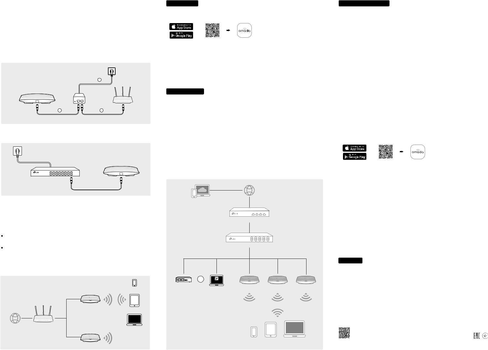
Power Supply
The EAP can be powered via a power adapter or a PSE device (such as a PoE switch) .
Via Power Adapter
1.Connect the Ethernet cable from the Ethernet port (ETH1 for EAP245) of the EAP device to the provided power adapter’s PoE port.
2.Connect an Ethernet cable from your LAN to the power adapter’s LAN port.
3.Connect the power cord to the adapter’s power socket. Connect the other end of the power cord to a standard electrical wall outlet.
|
3 |
PoE Adapter |
|
PoE |
LAN |
1 |
2 |
(Up to 100m)
Via PoE Switch
Connect an Ethernet cable from the PoE switch to the Ethernet port (ETH1 for EAP245).
PoE Switch
Software Configuration
A DHCP server (typically a router) with DHCP function enabled is required to assign IP addresses to the EAPs and clients in your local network.
The EAP supports two configuring options:
To configure and manage EAPs singly (usually suitable for a small network with a few EAPs), standalone mode is recommended. Please refer to Option 1.
To configure and manage EAPs in batch, controller mode is recommended. Please refer to Option 2.
Option1: Standalone Mode
|
Internet |
EAP |
REV3.1.0 |
|
|
|
|
|
7106508174 |
|
Router |
|
Clients |
|
|
|
|
TP-Link |
|
EAP |
©2018 |
|
|
|
|
Via Omada App
1.Download the TP-Link Omada app on your mobile device. It can be downloaded from Apple Store or Google Play:
or
Scan for Omada App Download Omada App
2.Connect your mobile device to the EAP by using the default SSID (format: TP-Link_2.4GHz/5GHz_XXXXXX) printed on the label.
3.Open the Omada app, and wait for the EAP device to appear on the Standalone APs page. Tap on the EAP device you want to configure.
The Omada app is designed to help you quickly configure the common settings. If you want to configure the advanced settings, you can log in to the web page of your EAP or the controller.
Via a Web Browser
1.Connect wirelessly by using the default SSID (format: TP-Link_2.4GHz/5GHz_XXXXXX) printed on the label.
2.Launch a web browser and enter http://tplinkeap.net in the address bar. Use admin for both Username and Password to log in.
3.Set up a new Username and Password for secure management purpose. Modify the wireless parameters and reconnect your wireless devices to the new wireless network.
To configure other EAPs, connect your device to the EAP by the coresponding default SSID and repeat the steps listed above. You can configure some basic functions in Standalone mode. If you want to configure advanced functions, please use Controller mode.
Option2: Controller Mode
Controller mode is applicable to configuration for mass EAPs. All EAPs can be centrally configured and monitored via an Omada Software Controller or an Omada Cloud Controller (OC200).
Router
Switch
|
Or |
Omada Controller |
|
|
|
OC200 |
Omada Software Controller |
EAP |
EAP |
EAP |
|
|
running on the Management PC |
|
|
|
|
Clients
Via Software Controller
1.On the PC with Windows OS or Linux OS, download the Omada Controller installation file from http://www.tp-link.com/en/download/EAP-Controller.html.
2.Run the file and follow the wizard to install the Omada Controller.
3.Launch the Omada Controller and follow the step-by-step instructions to complete the Quick Setup. After the wizard is finished, a login screen will appear.
4.Enter the username and password you created and click Log in. Then you can further configure the Omada Controller.
Omada Cloud Service
After installing Omada Controller, you can remotely access and configure the controller through cloud service. Follow the steps below.
1.Enable Cloud Access on the setting page on the controller and bind a TP-Link ID to your controller. If you have configured this in the setup wizard, skip the step.
2.Launch a web browser and enter https://omada.tplinkcloud.com in the address bar.
3.Enter your TP-Link ID and password to log in. A list of Omada Controller that has been bound with your TP-Link ID will appear. Then you can click Launch further configure the controller.
 Omada App
With Omada app, you can also manage your Omada Controller at local site and remote site. Note that Omada software Controller needs to be kept running when using Omada app.
1.Download the TP-Link Omada app on your mobile device. It can be downloaded from Apple Store or Google Play:
or
Scan for Omada App Download Omada App
2.Launch your app and configure the controller at local site or remote site.
 Local Management
a.Connect your mobile device to the EAP by using the default SSID (format: TP-Link_2.4GHz/5GHz_XXXXXX) printed on the label.
b.Launch the app and go to Local Access, tap the + button on the upper-right corner to add the Omada controller. Then you can further configure the controller.
 Remote Management
a.Make sure Cloud Access is enabled on your controller and your controller has been bound with a TP-Link ID.
b.Launch the app and log in with your TP-Link ID. Then go to Cloud Access. A list of Omada Controller that has been bound with your TP-Link ID will appear. Then you can further configure the controller.
Via OC200
Omada Softeware Controller is pre-installed on Omada Cloud Controller (OC200). OC200 needs to be purchased additionally. To configure EAPs via OC200, the steps above can be skipped. Please refer to the Installation Guide of OC200.
For detailed configurations, please visit https://www.tp-link.com/support to download the User Guide of EAP in the download center.
To ask questions, find answers, and communicate with TP-Link users or engineers, please visit https://community.tp-link.com to joinTP-Link Community.
For technical support and other information, please visit https://www.tp-link.com/support, or simply scan the QR code.
The products of TP-Link partly contain software code developed by third parties, including software code subject to the GNU General Public License (“GPL”). As applicable, the terms of the GPL and any information on obtaining access to the respective GPL Code used in TP-Link products are available to you in GPL-Code-Cen- tre under (http://www.tp-link.com/en/support/gpl/). The respective programs are distributed WITHOUT ANY WARRANTY and are subject to the copyrights of one or more authors. For details, see the GPL Code and other terms of the GPL.
 Loading...