


WEB version: Revision 0a
E6581611
Industrial Inverter
(For 3-phase induction motors)
Instruction Manual
<Detailed manual>
3-phase 240V class 0.4 to 15kW
1-phase 240V class 0.2 to 2.2kW
3-phase 500V class 0.4 to 15kW
NOTICE
1.Make sure that this instruction manual is delivered to the end user of the inverter unit.
2.Read this manual before installing or operating the inverter unit, and store it in a safe place for reference.
Safety precautions
Contents
Read rst
Connection
Operations
Setting parameters
Main parameters
Other parameters
Operation with external signal
Monitoring the operation status
Measures to satisfy the standards
Peripheral devices
Table of parameters and data
Speci cations
Before making a service call
Inspection and maintenance
Warranty
Disposal of the inverter
I
1
2
3
4
5
6
7
8
9
10
11
12
13
14
15
16

|
E6581611 |
||
|
|
|
|
I. Safety precautions |
|
|
I |
|
|
|
|
|
|
|
|
The items described in these instructions and on the inverter itself are very important so that you can use safely the inverter, prevent injury to yourself and other people around you as well as to prevent damage to property in the area. Thoroughly familiarize yourself with the symbols and indications shown below and then continue to read the manual. Make sure that you observe all warnings given.
Explanation of markings
Marking |
Meaning of marking |
Warning |
Indicates that errors in operation will lead to death or serious injury. |
Caution |
Indicates that errors in operation will lead to injury (*1) to people or that these errors will |
cause damage to physical property. (*2) |
(*1) Such things as injury, burns or shock that will not require hospitalization or long periods of outpatient treatment.
(*2) Physical property damage refers to wide-ranging damage to assets and materials.
Meanings of symbols
Marking |
Meaning of marking |
|
Indicates prohibition (Don't do it). |
|
What is prohibited will be described in or near the symbol in either text or picture form. |
|
Indicates an instruction that must be followed. |
|
Detailed instructions are described in illustrations and text in or near the symbol. |
|
-Indicates warning. |
|
What is warned will be described in or near the symbol in either text or picture form. |
|
-Indicates caution. |
|
What the caution should be applied to will be described in or near the symbol in either text or picture form. |
1
E6581611
|
|
|
|
|
I |
Limits in purpose |
|||
|
This inverter is used for controlling speeds of three-phase induction motors in general industrial use. |
|||
|
Single-phase input model is output by the inverter as three-phase output and cannot drive a single-phase motor. |
|||
|
|
|
|
Safety precautions |
|
|
|
|
|
|
|
|
|
|
|
|
This product is intended for general purpose uses in industrial application. It cannot be used |
||
|
|
applications where may cause big impact on public uses, such as power plant and railway, and |
||
|
|
equipment which endanger human life or injury, such as nuclear power control, aviation, space flight |
||
|
|
control, traffic, safety device, amusement, or medical. |
||
|
|
It may be considerable whether to apply, under the special condition or an application where strict |
||
|
|
quality control may not be required. Please contact your Toshiba distributor. |
||
|
|
Please use our product in applications where do not cause serious accidents or damages even if |
||
|
|
product is failure, or please use in environment where safety equipment is applicable or a backup circuit |
||
|
|
device is provided outside the system. |
||
|
|
Please do not use our product for any load other than three-phase induction motors in general |
||
|
|
industrial use. (Use in other than properly applied three-phase induction motors may cause an |
||
|
|
accident.) |
||
|
|
Single-phase input model is output by the inverter as three-phase output and cannot drive a single- |
||
|
|
phase motor. |
||
Handling
|
|
Warning |
Reference |
|
|
section |
|
|
|
Never disassemble, modify or repair. |
2. |
|
|
This can result in electric shock, fire and injury. Call your Toshiba distributor for repairs. |
|
Disassembly |
|
|
|
prohibited |
|
|
|
|
|
Never remove the terminal block cover when power is on. |
2.1 |
|
|
The unit contains many high voltage parts and contact with them will result in electric shock. |
2. |
|
Do not stick your fingers into openings such as cable wiring holes and cooling fan covers. |
||
|
|
This can result in electric shock or other injury. |
2. |
Prohibited |
Do not place or insert any kind of object (electrical wire cuttings, rods, wires etc.) into the |
||
|
inverter. |
2. |
|
|
|
This can result in electric shock or fire. |
|
|
Do not allow water or any other fluid to come in contact with the inverter. |
|
|
|
|
This can result in electric shock or fire. |
|
|
|
Turn the power on only after attaching the terminal block cover. |
2.1 |
|
|
If the power is turned on without the terminal block cover attached, this can result in |
|
|
|
electric shock or other injury. |
|
|
If the inverter begins to emit smoke or an unusual odor, or unusual sounds, immediately |
3. |
|
|
|
turn the power off. |
|
Mandatory |
|
Continuous use of the inverter in such a state will cause fire. Call your Toshiba distributor |
|
action |
|
for repairs. |
|
|
Always turn the power off if the inverter is not used for long periods of time since there is a |
3. |
|
|
|
possibility of malfunction caused by leaks, dust and other material. If power is left on with |
|
|
|
the inverter in that state, it can result in fire. |
|
2

E6581611
|
|
Caution |
Reference |
|
I |
|
|
section |
|
||
|
|
|
|
|
|
|
|
Do not touch heat radiating fins or discharge resistors. |
3. |
|
|
|
|
These devices are hot, and you'll get burned if you touch them. |
|
|
|
Contact |
|
|
|
|
|
prohibited |
|
|
|
|
|
|
|
Use an inverter that conforms to the specifications of power supply and three-phase |
1.1 |
|
|
|
|
induction motor being used. If the inverter being used does not conform to those |
1.4.1 |
|
|
|
|
specifications, not only will the three-phase induction motor not rotate correctly, but |
|
|
|
Mandatory |
|
it can also cause serious accidents through overheating and fire. |
|
|
|
|
|
|
|
|
|
action |
|
|
|
|
|
|
|
|
|
|
|
Transportation & installation |
|
|
|
||
|
|
|
|
|
|
|
|
Warning |
Reference |
|
|
|
|
section |
|
|
|
|
|
Do not install or operate the inverter if it is damaged or any component is missing. |
1.4.4 |
|
|
|
|
This can result in electric shock or fire. Call your Toshiba distributor for repairs. |
|
|
|
|
Do not place any inflammable objects near the inverter. |
1.4.4 |
|
|
|
Prohibited |
|
If an accident occurs in which flame is emitted, this could lead to fire. |
|
|
|
Do not install in any location where the inverter could come into contact with water or |
|
|
|
||
|
1.4.4 |
|
|
||
|
|
other fluids. |
|
|
|
|
|
This can result in electric shock or fire. |
|
|
|
|
|
Operate under the environmental conditions prescribed in the instruction manual. |
1.4.4 |
|
|
|
|
Operations under any other conditions can result in malfunction. |
1.4.4 |
|
|
|
Mount the inverter on a metal plate. |
|
|
||
|
|
The rear panel gets very hot. Do not install in an inflammable object, this can result in fire. |
1.4.4 |
|
|
|
Do not operate with the terminal block cover removed. This can result in electric shock. |
|
|
||
|
|
Failure to do so can lead to risk of electric shock and can result in death or serious injury. |
1.4.4 |
|
|
Mandatory |
An emergency stop device must be installed that fits with system specifications (e.g. shut |
|
|
||
|
off input power then engage mechanical brake). Operation cannot be stopped immediately |
|
|
|
|
action |
|
by the inverter alone, thus resulting in an accident or injury. |
1.4.4 |
|
|
|
All options used must be those specified by Toshiba. |
|
|
||
|
|
The use of any other option will result in an accident. |
10 |
|
|
|
When using switchgear for the inverter, it must be installed in a cabinet. |
|
|
||
|
|
Failure to do so can lead to risk of electric shock. |
|
|
|
|
|
|
|
|
|
|
|
Caution |
Reference |
|
|
|
|
section |
|
|
|
|
|
When transporting or carrying, do not hold by the front panel covers. |
2. |
|
|
|
|
The covers will come off and the unit will drop, resulting in injury. |
|
|
|
Prohibited |
Do not install in any area where the unit would be subject to large amounts of vibration. |
1.4.4 |
|
|
|
|
This could cause the unit to fall, resulting in bodily injury. |
|
|
|
|
3

|
|
|
|
|
|
E6581611 |
|
|
|
|
|
|
|
|
|
I |
|
|
|
|
|
|
|
|
|
|
|
Caution |
Reference |
|
|
|
|
|
section |
|
|||
|
|
|
|
|
|
|
|
|
|
|
|
|
When removing and installing the terminal cover with a screwdriver, be sure not to scratch |
1.3.2 |
|
|
|
|
|
|
your hand as these results in injury. |
1.3.2 |
|
|
|
|
|
Pressing too hard on the screwdriver can scratch the inverter. |
|
||
|
|
|
|
|
Always turn the power off when removing the wiring cover. |
1.3.2 |
|
|
|
|
|
|
After wiring is complete, be sure to replace the terminal cover. |
1.3.2 |
|
|
|
|
Mandatory |
|
The main unit must be installed on a base that can bear the unit's weight. |
1.4.4 |
|
|
|
|
action |
|
If the unit is installed on a base that cannot withstand that weight, the unit can fall, |
|
|
|
|
|
|
|
resulting in injury. |
1.4.4 |
|
|
|
|
|
If braking is necessary (to hold motor shaft), install a mechanical brake. |
|
||
|
|
|
|
|
The brake on the inverter will not function as a mechanical hold, and if used for that |
|
|
|
|
|
|
|
purpose, injury will result. |
|
|
|
|
Wiring |
|
|
|
|
|
|
|
|
|
|
|
|
|
|
|
|
|
|
Warning |
Reference |
|
|
|
|
|
|
section |
|
|
|
|
|
|
|
Do not connect input power to the output (motor side) terminals (U/T1, V/T2, W/T3). |
2.2 |
|
|
|
|
|
|
Connecting input power to the output could destroy the inverter or cause a fire. |
2.2 |
|
|
|
|
|
Do not insert a braking resistor between DC terminals (between PA/+ and PC/- or PO and |
|
||
|
|
|
|
|
PC/-). |
|
|
|
|
|
|
|
It could cause a fire. |
2.2 |
|
|
|
|
Prohibited |
First shut off input power and wait at least 15 minutes before touching terminals and wires |
|
||
|
|
|
|
on equipment (MCCB) that is connected to inverter power side. |
|
|
|
|
|
|
|
|
Touching the terminals and wires before that time could result in electric shock. |
2.2 |
|
|
|
|
|
Do not shut down the external power supply on ahead when VIA terminal is used as logic |
|
||
|
|
|
|
|
input terminal by external power supply. |
|
|
|
|
|
|
|
It could cause unexpected result as VIA terminal is ON status. |
|
|
|
|
|
|
|
Electrical construction work must be done by a qualified expert. |
2.1 |
|
|
|
|
|
|
Connection of input power by someone who does not have that expert knowledge can |
|
|
|
|
|
|
|
result in fire or electric shock. |
2.1 |
|
|
|
|
|
Connect output terminals (motor side) correctly. |
|
||
|
|
|
|
|
If the phase sequence is incorrect, the motor will operate in reverse and that can result in |
|
|
|
|
|
|
|
injury. |
2.1 |
|
|
|
|
|
Wiring must be done after installation. |
|
||
|
|
|
|
|
If wiring is done prior to installation, that can result in injury or electric shock. |
2.1 |
|
|
|
|
|
The following steps must be performed before wiring. |
|
||
|
|
|
|
|
(1) Turn off all input power. |
|
|
|
|
|
|
|
(2) Wait at least 15 minutes and check to make sure that the charge lamp is no longer lit. |
|
|
|
|
|
|
|
(3) Use a tester that can measure DC voltage (400VDC or 800VDC or more), and check to |
|
|
|
|
|
Mandatory |
|
make sure that the voltage to the DC main circuits (across PA/+ - PC/-) is 45V or less. |
|
|
|
|
|
action |
|
If these steps are not properly performed, the wiring will cause electric shock. |
2.1 |
|
|
|
|
|
Tighten the screws on the terminal block to specified torque. |
|
||
|
|
|
|
|
If the screws are not tightened to the specified torque, it can lead to fire. |
1.4.4 |
|
|
|
|
|
Check to make sure that the input power voltage is +10%, -15% of the rated power |
|
||
|
|
|
|
|
voltage (±10% when the load is 100% in continuous operation) written on the name plate. |
|
|
|
|
|
|
|
If the input power voltage is not +10%, -15% of the rated power voltage (±10% when the |
|
|
|
|
|
|
|
load is 100% in continuous operation), this can result in fire. |
2.2 |
|
|
|
|
|
Set a parameter f109 when VIA or VIB terminals are used as logic input terminal. |
|
||
|
|
|
|
|
If it is not set, it could result in malfunction. |
2.2 |
|
|
|
|
|
Set a parameter f147 when S3 terminal is used as PTC input terminal. |
|
||
|
|
|
|
|
If it is not set, it could result in malfunction. |
|
|
|
|
|
|
|
|
|
|
|
|
|
|
|
4 |
|
|

E6581611
|
|
|
Warning |
Reference |
|
|
I |
|
|
|
section |
|
|
||
|
|
|
|
|
|
|
|
|
|
|
Ground must be connected securely. |
2.1 |
|
|
|
|
|
|
If the ground is not securely connected, it could lead to electric shock or fire. |
2.2 |
|
|
|
|
Be Grounded |
|
|
10. |
|
|
|
|
|
|
|
|
|
|
|
|
|
|
|
|
|
|
|
|
|
|
Caution |
Reference |
|
|
|
|
|
|
section |
|
|
|
|
|
|
|
Do not attach devices with built-in capacitors (such as noise filters or surge absorbers) to |
2.1 |
|
|
|
|
|
|
the output (motor side) terminals. |
|
|
|
|
|
Prohibited |
|
This could cause a fire. |
|
|
|
|
|
|
|
|
|
|
|
|
Operations |
|
|
|
|
|||
|
|
|
|
|
|
|
|
|
|
|
Warning |
Reference |
|
|
|
|
|
|
section |
|
|
|
|
|
|
|
Never touch the internal connector while the upper terminal cover of control panel is |
1.3.2 |
|
|
|
|
|
|
opened. |
|
|
|
|
|
|
|
There is a risk of electrical shock because it carries a high voltage. |
3. |
|
|
|
|
|
Do not touch inverter terminals when electrical power is going to the inverter even if the |
|
|
|
||
|
|
|
motor is stopped. |
|
|
|
|
|
|
|
Touching the inverter terminals while power is connected to it will result in electric shock. |
3. |
|
|
|
|
Prohibited |
Do not touch switches when the hands are wet and do not try to clean the inverter with a |
|
|
|
||
|
|
damp cloth. |
|
|
|
|
|
|
|
|
Such practices will result in electric shock. |
|
|
|
|
|
|
Do not go near the motor in alarm-stop status when the retry function is selected. |
3. |
|
|
|
|
|
|
|
The motor will suddenly restart and that could result in injury. |
|
|
|
|
|
|
|
Take measures for safety, e.g. attaching a cover to the motor, against accidents when the |
|
|
|
|
|
|
|
motor unexpectedly restarts. |
|
|
|
|
|
|
|
Turn the input power on only after attaching the terminal block cover. |
3. |
|
|
|
|
|
|
When enclosed inside a cabinet and used with the terminal block cover removed, always |
|
|
|
|
|
|
|
close the cabinet doors first and then turn the power on. If the power is turned on with the |
|
|
|
|
|
|
|
terminal block cover or cabinet doors open can result in electric shock. |
|
|
|
|
|
Mandatory |
Make sure that operation signals are off before resetting the inverter after malfunction. |
3. |
|
|
|
|
|
action |
|
If the inverter is reset before turning off the operating signal, the motor can restart |
|
|
|
|
|
|
suddenly, resulting in injury. |
|
|
|
|
|
|
|
|
3.1 |
|
|
|
|
|
|
If incorrect setting, the drive will have some damage or unexpected movement. Be sure to |
|
|
|
||
|
|
|
set the setup menu correctly. |
|
|
|
|
|
|
|
|
|
|
|
|
|
|
|
Caution |
Reference |
|
|
|
|
|
|
section |
|
|
|
|
|
|
|
Observe all permissible operating ranges of motors and mechanical equipment. (Refer to |
3. |
|
|
|
|
|
|
the motor's instruction manual.) |
|
|
|
|
|
|
|
Not observing these ranges will result in injury. |
6.29.2 |
|
|
|
|
|
Do not set the stall prevention level ( ) extremely low. |
|
|
|
||
|
|
|
If the stall prevention level parameter ( ) is set at or below the no-load current of |
|
|
|
|
|
Prohibited |
|
the motor, the stall preventive function will be always active and increase the frequency |
|
|
|
|
|
|
when it judges that regenerative braking is taking place. |
|
|
|
|
|
|
|
|
|
|
|
|
|
|
|
|
Do not set the stall prevention level parameter ( ) below 30% under normal use |
|
|
|
|
|
|
|
conditions. |
|
|
|
|
|
|
|
|
|
|
|
|
|
|
|
5 |
|
|
|
|

|
|
|
|
|
|
E6581611 |
|
|
|
|
|
|
|
|
|
I |
|
|
|
|
|
|
|
|
|
|
|
Caution |
Reference |
|
|
|
|
|
section |
|
|||
|
|
|
|
|
|
|
|
|
|
|
|
|
Use an inverter that conforms to the specifications of power supply and three-phase |
1.4.1 |
|
|
|
|
|
|
induction motor being operated. If the inverter being used does not conform to those |
|
|
|
|
|
|
|
specifications, not only will the three-phase induction motor not rotate correctly, but it will |
|
|
|
|
|
Mandatory |
|
cause serious accidents through overheating and fire. |
1.4.3 |
|
|
|
|
The leakage current through the input/output power cables of inverter and capacitance of |
|
|||
|
|
|
action |
|
motor can affect to peripheral devices. |
|
|
|
|
|
|
|
The value of leakage current is increased under the condition of the PWM carrier |
|
|
|
|
|
|
|
frequency and the length of the input/output power cables. In case the total cable length |
|
|
|
|
|
|
|
(total of length between an inverter and motors) is more than 100m, overcurrent trip can |
|
|
|
|
|
|
|
occur even the motor no-load current. |
|
|
|
|
|
|
|
Make enough space among each phase cable or install the filter (MSF) as |
|
|
|
|
|
|
|
countermeasure. |
|
|
|
|
|
When operation by using remote keypad is selected |
|
|
||
|
|
|
|
|
|
|
|
|
|
|
|
|
Warning |
Reference |
|
|
|
|
|
|
section |
|
|
|
|
|
|
|
Set the parameter Communication time-out time (f803), Communication time-out |
6.38.1 |
|
|
|
|
|
|
action (f804) and Disconnection detection of extension panel (f731). |
|
|
|
|
|
|
|
If these are not properly set, the inverter can not be stopped immediately in breaking |
|
|
|
|
|
Mandatory |
|
communication and this could result in injury and accidents. |
6.38.1 |
|
|
|
|
An emergency stop device and the interlock that fit with system specifications must be |
|
|||
|
|
|
action |
|
installed. |
|
|
|
|
|
|
|
If these are not properly installed, the inverter can not be stopped immediately and this |
|
|
|
|
|
|
|
could result in injury and accidents. |
|
|
|
|
When sequence for restart after a momentary failure is selected (inverter) |
|||||
|
|
|
|
|
|
|
|
|
|
|
|
|
Caution |
Reference |
|
|
|
|
|
|
section |
|
|
|
|
|
|
|
Stand clear of motors and mechanical equipment. |
5.9 |
|
|
|
|
|
|
If the motor stops due to a momentary power failure, the equipment will start suddenly |
|
|
|
|
|
Mandatory |
|
after power is restored. This could result in unexpected injury. |
5.9 |
|
|
|
|
Attach caution label about sudden restart after a momentary power failure on inverters, |
|
|||
|
|
|
action |
|
motors and equipment for prevention of accidents in advance. |
|
|
|
|
|
|
|
|
|
|
|
|
When retry function is selected (inverter) |
|
|
|||
|
|
|
|
|
|
|
|
|
|
|
|
|
Caution |
Reference |
|
|
|
|
|
|
section |
|
|
|
|
|
|
|
Stand clear of motors and equipment. |
6.19.3 |
|
|
|
|
|
|
If the motor and equipment stop when the alarm is given, selection of the retry function will |
|
|
|
|
|
|
|
restart them suddenly after the specified time has elapsed. This could result in unexpected |
|
|
|
|
|
Mandatory |
|
injury. |
|
|
|
|
|
action |
|
Attach caution label about sudden restart in retry function on inverters, motors and |
6.19.3 |
|
|
|
|
|
|
equipment for prevention of accidents in advance. |
|
|
6
|
|
|
|
E6581611 |
|||
|
|
|
|
|
|
|
|
Maintenance and inspection |
|
|
|
I |
|||
|
|
|
|
|
|
||
|
|
|
Warning |
Reference |
|
||
|
|
|
section |
|
|||
|
|
|
Do not replace parts. |
14.2 |
|
|
|
|
|
|
This could be a cause of electric shock, fire and bodily injury. To replace parts, call your |
|
|
|
|
|
Prohibited |
|
Toshiba distributor. |
|
|
|
|
|
|
|
|
|
|
|
|
|
|
|
The equipment must be inspected daily. |
14. |
|
|
|
|
|
|
If the equipment is not inspected and maintained, errors and malfunctions can not be |
|
|
|
|
|
|
|
discovered and that could result in accidents. |
|
|
|
|
|
|
Before inspection, perform the following steps. |
14. |
|
|
|
|
|
|
|
(1) Turn off all input power to the inverter. |
14.2 |
|
|
|
|
Mandatory |
|
(2) Wait at least 15 minutes and check to make sure that the charge lamp is no longer lit. |
|
|
|
|
|
action |
|
(3) Use a tester that can measure DC voltages (400V/800V DC or more), and check that |
|
|
|
|
|
|
|
the voltage to the DC main circuits (across PA/+ - PC/-) is 45V or less. |
|
|
|
|
|
|
|
Performing an inspection without carrying out these steps first could lead to electric shock. |
|
|
|
|
Disposal |
|
|
|
|
|
||
|
|
|
|
|
|||
|
|
|
Caution |
Reference |
|
||
|
|
|
section |
|
|||
|
|
|
If you dispose of the inverter, have it done by a specialist in industry waste disposal (*). |
16. |
|
|
|
|
|
|
If you dispose of the inverter by yourself, this can result in explosion of capacitor or |
|
|
|
|
|
|
|
produce noxious gases, resulting in injury. |
|
|
|
|
|
Mandatory |
(*) Persons who specialize in the processing of waste and known as "industrial waste |
|
|
|
|
|
|
|
product collectors and transporters" or "industrial waste disposal persons”. Please |
|
|
|
|
|
|
action |
|
observe any applicable law, regulation, rule or ordinance for industrial waste disposal. |
|
|
|
|
Attach caution labels
Shown here are examples of caution labels to prevent, in advance, accidents in relation to inverters, motors and other equipment. Be sure to affix the caution label where it is easily visible when selecting the auto-restart function (5.9) or the retry function (6.19.3).
If the inverter has been programmed for restart sequence of momentary power failure, place warning labels in a place where they can be easily seen and read.
(Example of caution label)
Caution (Functions programmed for restart)
Do not go near motors and equipment. Motors and equipment that have stopped temporarily after momentary power failure will restart suddenly after recovery.
If the retry function has been selected, place warning labels in a location where they can be easily seen and read.
(Example of caution label)
Caution (Functions programmed for retry)
Do not go near motors and equipment. Motors and equipment that have stopped temporarily after an alarm will restart suddenly after the specified time has elapsed.
7

|
|
|
E6581611 |
|
|
|
|
Contents |
|
|
|
I |
Safety precautions......................................................................................................................................................... |
1 |
|
|
|
1. |
Read first |
A-1 |
|
|
|
|
|
||||
|
1.1 |
Check product purchase.................................................................................................................................... |
A-1 |
|
|
|
1.2 |
.....................................................................................................................................Contents of the product |
A-2 |
|
|
|
1.3 |
Names and functions......................................................................................................................................... |
A-3 |
|
|
|
1.4 |
Notes on the application .................................................................................................................................... |
A-22 |
|
|
2. |
Connection .................................................................................................................................................................... |
B-1 |
|
|
|
|
2.1 |
Cautions on wiring ............................................................................................................................................. |
B-1 |
|
|
|
2.2 |
Standard connections ........................................................................................................................................ |
B-3 |
|
|
|
2.3 |
Description of terminals ..................................................................................................................................... |
B-6 |
|
|
3. |
Operations ..................................................................................................................................................................... |
C-1 |
|
|
|
|
3.1 |
How to Set the Setup Menu............................................................................................................................... |
C-2 |
|
|
|
3.2 |
Simplified Operation of the VF-S15 ................................................................................................................... |
C-4 |
|
|
|
3.3 |
How to operate the VFS15 .............................................................................................................................. |
C-8 |
|
|
4. |
Setting parameters ........................................................................................................................................................ |
D-1 |
|
|
|
|
4.1 |
Setting and Display Modes ................................................................................................................................ |
D-1 |
|
|
|
4.2 |
How to set parameters....................................................................................................................................... |
D-3 |
|
|
|
4.3 |
Functions useful in searching for a parameter or changing a parameter setting................................................ |
D-7 |
|
|
|
4.4 |
Checking the region settings selection .............................................................................................................. |
D-13 |
|
|
|
4.5 |
EASY key function ............................................................................................................................................. |
D-14 |
|
|
5. |
Main parameters............................................................................................................................................................ |
E-1 |
|
|
|
|
5.1 |
Meter setting and adjustment ............................................................................................................................ |
E-1 |
|
|
|
5.2 |
Setting acceleration/deceleration time ............................................................................................................... |
E-4 |
|
|
|
5.3 |
Maximum frequency .......................................................................................................................................... |
E-5 |
|
|
|
5.4 |
Upper limit and lower limit frequencies .............................................................................................................. |
E-6 |
|
|
|
5.5 |
Base frequency.................................................................................................................................................. |
E-7 |
|
|
|
5.6 |
Setting the electronic thermal ............................................................................................................................ |
E-8 |
|
|
|
5.7 |
Preset-speed operation (speeds in 15 steps) .................................................................................................... |
E-16 |
|
|
|
5.8 |
Switching between two frequency commands ................................................................................................... |
E-19 |
|
|
|
5.9 |
Auto-restart (Restart of coasting motor)............................................................................................................. |
E-21 |
|
|
|
5.10 |
Changing operation panel display...................................................................................................................... |
E-23 |
|
|
6. |
Other parameters........................................................................................................................................................... |
F-1 |
|
|
|
|
6.1 |
Parameters useful for setting and adjustments.................................................................................................. |
F-2 |
|
|
|
6.2 |
Selection of operation mode .............................................................................................................................. |
F-12 |
|
|
|
6.3 |
Selecting control mode ...................................................................................................................................... |
F-17 |
|
|
i

|
|
|
|
E6581611 |
|
|
6.4 |
Manual torque boost - increasing torque boost at low speeds ........................................................................... |
F-24 |
|
|
6.5 |
Signal output ...................................................................................................................................................... |
F-25 |
|
|
6.6 |
Input signal selection.......................................................................................................................................... |
F-28 |
|
|
6.7 |
Terminal function selection................................................................................................................................. |
F-31 |
|
|
6.8 |
Basic parameters 2 |
F-33 |
|
|
|||
|
|
6.9 |
V/f 5-point setting ............................................................................................................................................... |
F-35 |
|
|
6.10 |
Frequency priority selection ............................................................................................................................... |
F-35 |
|
|
|||
|
|
6.11 |
Operation frequency........................................................................................................................................... |
F-44 |
|
|
6.12 |
DC braking ......................................................................................................................................................... |
F-46 |
|
|
6.13 |
Stop at lower-limit frequency operation (sleep function)..................................................................................... |
F-48 |
|
|
6.14 |
Jog run mode ..................................................................................................................................................... |
F-49 |
|
|
6.15 |
Jump frequency - avoiding resonant frequencies............................................................................................... |
F-51 |
|
|
6.16 |
Bumpless operation ........................................................................................................................................... |
F-52 |
|
|
6.17 |
Low voltage operation ........................................................................................................................................ |
F-54 |
|
|
6.18 |
PWM carrier frequency ...................................................................................................................................... |
F-54 |
|
|
6.19 |
Trip-less intensification....................................................................................................................................... |
F-60 |
|
|
6.20 |
Drooping control................................................................................................................................................. |
F-73 |
|
|
6.21 |
Light-load high-speed operation function ........................................................................................................... |
F-75 |
|
|
6.22 |
Braking function ................................................................................................................................................. |
F-75 |
|
|
6.23 |
Acceleration/deceleration suspend function (Dwell function) ............................................................................. |
F-76 |
|
|
6.24 |
PID control ......................................................................................................................................................... |
F-78 |
|
|
6.25 |
Setting motor constants...................................................................................................................................... |
F-85 |
|
|
6.26 |
Torque limit......................................................................................................................................................... |
F-91 |
|
|
6.27 |
Acceleration/deceleration time 2 and 3 .............................................................................................................. |
F-96 |
|
|
6.28 |
Shock monitoring function.................................................................................................................................. |
F-100 |
|
|
6.29 |
Protection functions............................................................................................................................................ |
F-101 |
|
|
6.30 |
Forced fire-speed control function...................................................................................................................... |
F-115 |
|
|
6.31 |
Override ............................................................................................................................................................. |
F-116 |
|
|
6.32 |
Analog input terminal function selection............................................................................................................. |
F-119 |
|
|
6.33 |
Adjustment parameters ...................................................................................................................................... |
F-120 |
|
|
6.34 |
Operation panel parameter ................................................................................................................................ |
F-124 |
|
|
6.35 |
Tracing functions................................................................................................................................................ |
F-134 |
|
|
6.36 |
Integrating wattmeter ......................................................................................................................................... |
F-134 |
|
|
6.37 |
Parameter registration to easy setting mode...................................................................................................... |
F-134 |
|
|
6.38 |
Communication function..................................................................................................................................... |
F-135 |
|
|
6.39 |
Permanent magnet motors................................................................................................................................. |
F-143 |
|
|
6.40 |
Traverse function ............................................................................................................................................... |
F-144 |
|
|
7. Operations with external signal ...................................................................................................................................... |
G-1 |
|
|
|
7.1 |
Operating external signals ................................................................................................................................. |
G-1 |
|
|
7.2 |
Applied operations by an I/O signal (operation from the terminal block) ............................................................ |
G-2 |
|
|
7.3 |
Speed instruction (analog signal) settings from external devices....................................................................... |
G-12 |
ii
|
|
|
E6581611 |
|
|
8. |
Monitoring the operation status ..................................................................................................................................... |
H-1 |
|
|
|
|
8.1 |
Flow of status monitor mode.............................................................................................................................. |
H-1 |
|
|
|
8.2 |
Status monitor mode.......................................................................................................................................... |
H-2 |
|
|
|
8.3 |
Display of trip information .................................................................................................................................. |
H-6 |
|
|
9. |
Measures to satisfy the standards |
I-1 |
|
|
|
|
|
||||
|
9.1 |
How to cope with the CE Marking Directive....................................................................................................... |
I-1 |
|
|
|
|
|
|||
|
9.2 |
Compliance with UL Standard and CSA Standard ............................................................................................. |
I-6 |
|
|
10. Peripheral devices ......................................................................................................................................................... |
J-1 |
|
|
||
|
10.1 |
Selection of wiring materials and devices .......................................................................................................... |
J-1 |
|
|
|
10.2 |
Installation of a magnetic contactor ................................................................................................................... |
J-4 |
|
|
|
10.3 |
Installation of an overload relay ......................................................................................................................... |
J-5 |
|
|
|
10.4 |
Optional external devices .................................................................................................................................. |
J-6 |
|
|
11. |
Table of parameters and data ........................................................................................................................................ |
K-1 |
|
|
|
|
11.1 |
Frequency setting parameter............................................................................................................................. |
K-1 |
|
|
|
11.2 |
Basic parameters............................................................................................................................................... |
K-1 |
|
|
|
11.3 |
Extended parameters ........................................................................................................................................ |
K-5 |
|
|
|
11.4 |
Default settings by inverter rating ...................................................................................................................... |
K-28 |
|
|
|
11.5 |
Default settings by setup menu ......................................................................................................................... |
K-29 |
|
|
|
11.6 |
Input Terminal Function ..................................................................................................................................... |
K-30 |
|
|
|
11.7 |
Output Terminal Function................................................................................................................................... |
K-34 |
|
|
|
11.8 |
Application easy setting ..................................................................................................................................... |
K-38 |
|
|
|
11.9 |
Unchangeable parameters in running................................................................................................................ |
K-39 |
|
|
12. |
Specifications................................................................................................................................................................. |
L-1 |
|
|
|
|
12.1 |
Models and their standard specifications........................................................................................................... |
L-1 |
|
|
|
12.2 |
Outside dimensions and mass........................................................................................................................... |
L-4 |
|
|
13. Before making a service call - Trip information and remedies ....................................................................................... |
M-1 |
|
|
||
|
13.1 |
Trip/Alarm causes and remedies ....................................................................................................................... |
M-1 |
|
|
|
13.2 |
Restoring the inverter from a trip ....................................................................................................................... |
M-7 |
|
|
|
13.3 |
If the motor does not run while no trip message is displayed ............................................................................ |
M-8 |
|
|
|
13.4 |
How to determine the causes of other problems................................................................................................ |
M-9 |
|
|
14. |
Inspection and maintenance.......................................................................................................................................... |
N-1 |
|
|
|
|
14.1 |
Regular inspection............................................................................................................................................. |
N-1 |
|
|
|
14.2 |
Periodical inspection.......................................................................................................................................... |
N-2 |
|
|
|
14.3 |
Making a call for servicing ................................................................................................................................. |
N-5 |
|
|
|
14.4 |
Keeping the inverter in storage.......................................................................................................................... |
N-5 |
|
|
iii

|
|
|
|
E6581611 |
|
|
15. |
Warranty......................................................................................................................................................................... |
O-1 |
|
|
16. |
Disposal of the inverter .................................................................................................................................................. |
P-1 |
|
|
|
|
|
|
|
|
|
|
iv
|
|
|
|
|
|
|
|
|
|
E6581611 |
|
|
1. |
Read first |
|
|
|||||||||
|
|
|
1.1 |
Check product purchase |
|
|
||||||
|
|
|
Before using the product you have purchased, check to make sure that it is exactly what you ordered. |
|
|
|||||||
|
|
|
|
|
|
|
Caution |
|
1 |
|||
|
|
|
|
|
|
Use an inverter that conforms to the specifications of power supply and three-phase induction |
|
|
||||
|
|
|
|
|
|
motor being used. If the inverter being used does not conform to those specifications, not only will |
|
|
||||
|
|
|
Mandatory |
|
|
the three-phase induction motor not rotate correctly, but it can also cause serious accidents |
|
|
||||
|
|
|
|
|
through overheating and fire. |
|
|
|||||
|
|
|
action |
|
|
|
|
|||||
|
|
|
|
|
|
|
|
|
|
|
|
|
|
|
|
|
|
|
|
|
|
|
|
|
|
|
|
|
|
|
|
|
Inverter main unit |
|
|
|
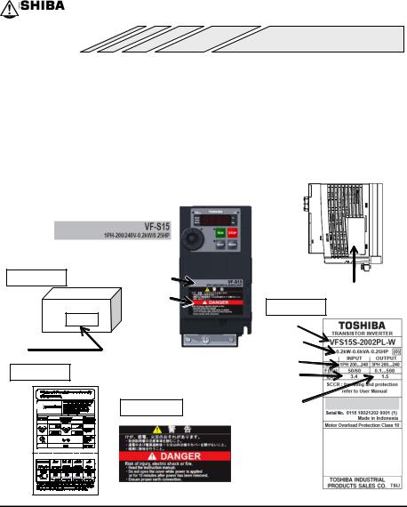
||
|
Rating label |
|
|
|
|
|
|
|||||
|
|
|
|
|
|
|
|
|
|
|||
|
Model |
|
|
|
|
|
|
|
|
|
||
|
|
|
|
|
|
|
|
|
|
|||
|
Power supply |
|
|
|
|
|
|
|
|
|
||
|
Motor capacity |
|
|
|
|
|
|
|
|
|
||
Carton box |
Rating label |
Name plate |
|
|
|
|
Danger label |
Name plate |
|
|
|
|
|
Inverter Type |
Type indication label |
|
Inverter rated |
|
output capacity |
|
|
|
Power supply |
Setup sheet |
|
Rated input |
|
|
current |
|
Danger label |
Rated output |
|
current |
A-1
E6581611
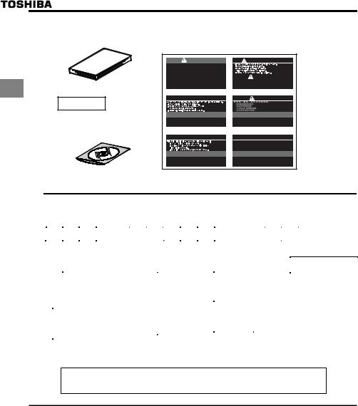
Quick start manual |
|
Danger label kit |
Danger labels for sticking in 6 languages.
1
CD-ROM
Contains the instruction manual in digital form
WDANGERRNING |
ADVERTENCIA |
Risk of injury, electric shock or fire.
Read the instruction manual. |
|
|
Do not open the cover while power is applied |
|
|
DANGER |
||
or for 15 minutes after power has been removed. |
||
Ensure proper earth connection. |
Risk of injury, electric shock or fire. |
|
Read the instruction manual. Ensure proper earth connection. |
||
|
Do not open the cover while power is applied |
|
|
or for 15 minutes after power has been removed. |
 WARNUNG
 DANGER
Risk of injury, electric shock or fire.
Read the instruction manual. Ensure proper earth connection. Do not open the cover while power is applied
or for 15 minutes after power has been removed.
 AVVERTENZA
 DANGER
Risk of injury, electric shock or fire.
Read the instruction manual. Ensure proper earth connection. Do not open the cover while power is applied
or for 15 minutes after power has been removed.
 DANGER
Risk of injury, electric shock or fire.
Read the instruction manual. Ensure proper earth connection. Do not open the cover while power is applied
or for 15 minutes after power has been removed.
 AVERTISSEMENT
Risque de blessure, d’électrocution ou d’incendie. Lire le manuel d’instruction.
Avant d’intervenir dans le variateur couper la puissance et attendre 15 minutes avant d’ouvrir le couvercle.
Assurer un raccordement approprié à la terre.
 DANGER
Risk of injury, electric shock or fire.
Read the instruction manual. Ensure proper earth connection. Do not open the cover while power is applied
or for 15 minutes after power has been removed.
English
Germany / English
Italian / English
Spanish / English
Chinese / English
France / English
1.2Contents of the product
Explanation of the name plate label
|
|
|
Type |
|
|
|
|
|
|
|
- |
|
|
|
|
|
|
Form |
|
|
|
|
|
|||||||||||||||
V |
F |
S |
1 |
5 |
|
S |
|
2 |
0 |
0 |
7 |
|
P |
L |
- W |
|
|
|||||||||||||||||||||
|
|
|
|
|
|
|
|
|
|
|
|
|
|
|
|
|
|
|
|
|
|
|
|
|
|
|
|
|
|
|
|
|
|
|
|
|
||
|
|
|
|
|
|
|
|
|
|
|
|
|
|
|
|
|
|
|
|
|
|
|
|
|
|
|
|
|
|
|
|
|
|
|
|
|
|
|
|
|
|
|
|
|
|
|
|
|
|
|
|
|
|
|
|
|
|
|
|
|
|
|
|
|
|
|
|
|
|
|
|
|
|
|
|
|
|
|
|
Model name |
|
|
Input (AC) voltage |
|
Applicable motor |
|
|
Additional functions I |
|
|
|
Additional functions |
||||||||||||||||||||||||
|
|
|
|
|
|
|
capacity |
|
|
|
|
|
||||||||||||||||||||||||||
|
|
|
|
|
|
|
|
|
|
|
|
|
|
|
|
|
|
|
|
|
|
|
|
|
|
|
|
|
|
|
|
|
|
|
||||
|
|
|
|
|
|
|
|
|
|
|
|
|
|
|
|
|
|
|
|
|
|
|
|
|
|
|
|
|
|
|
|
|
|
|
||||
|
|
TOSVERT |
|
|
2 : 200V to 240V |
|
002 |
: |
0.2kW |
|
|
L: Built-in high-attenuation |
|
W: W orld model |
||||||||||||||||||||||||
|
|
VF-S15 series |
|
|
4 : 380V to 500V |
|
004 |
: |
0.4kW |
|
|
EMC filter |
|
None: Japanese model |
||||||||||||||||||||||||
|
|
|
|
|
|
|
|
|
007 |
: 0.75kW |
|
|
M: Built-in basic filter |
|
|
|
|
|
||||||||||||||||||||
|
|
|
|
|
|
|
|
|
|
|
|
|
|
|
|
|
|
|
|
|
|
|||||||||||||||||
|
|
|
|
|
|
|
|
|
|
|
|
|
|
|
015 |
: |
1.5kW |
|
|
|
|
|
|
|
|
|
|
|
|
|
|
|
|
|
|
|||
|
|
|
|
|
|
|
|
|
|
|
|
|
|
|
|
|
|
|
|
|
|
|
|
|
|
|
|
|
|
|
|
|
||||||
|
|
|
|
|
|
|
|
|
|
|
|
|
|
|
022 |
: |
2.2kW |
|
|
|
|
|
|
|
|
|
|
|
|
|
|
|
|
|
|
|||
|
|
|
|
|
|
|
|
|
|
|
|
|
|
|
037 |
: |
4.0kW |
|
|
Operation panel |
|
|
|
|
|
|
|
|
|
|||||||||
|
Number of power |
|
|
|
|
|
|
|
|
|
|
055 |
: |
5.5kW |
|
|
|
|
|
|
|
|
|
|
|
|
|
|
|
|
|
|
||||||
|
|
phases |
|
|
|
|
|
|
|
|
|
|
075 |
: |
7.5kW |
|
|
P: Provided |
|
|
|
|
|
|
|
|
|
|||||||||||
|
S: single-phase |
|
|
|
|
|
|
|
|
|
|
110 |
: |
11kW |
|
|
|
|
|
|
|
|
|
|
|
|||||||||||||
|
|
|
|
|
|
|
|
|
|
|
|
|
|
|
|
|
|
|
|
|
|
|
|
|
|
|
|
|
||||||||||
|
None:three-phase |
|
|
|
|
|
|
|
|
|
|
150 |
: |
15kW |
|
|
|
|
|
|
|
|
|
|
|
|
|
|
|
|
|
|
||||||
|
|
|
|
|
|
|
|
|
|
|
|
|
|
|
|
|
|
|
|
|
|
|
|
|
|
|
|
|
||||||||||
|
|
|
|
|
|
|
|
|
|
|
|
|
|
|
|
|
|
|
|
|
|
|
|
|
|
|
|
|
|
|
|
|
|
|
|
|
|
|
Note 1) Always shut power off first then check the ratings label of inverter held in a cabinet.
Note 2) ID label is stuck for special specification product.
This instruction manual is for the “Ver. 102” or “Ver104” CPU version of the inverter.
The function in this manual may not be partially realized in the previous CPU version.
Please be informed that CPU version will be frequently upgraded.
A-2
E6581611
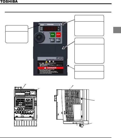
1.3Names and functions
1.3.1 Outside view
Charge lamp
STATUS lamp
Lights and blinks when using CANopen® communication option.
[Front view]
Hole for control circuit wiring
RS485 connector
Hole for main
 circuit wiring
Indicates there is a high voltage still in the inverter.
Do not open the terminal 1 block cover when this lamp
is lit because it is dangerous.
Cover
This is the body and terminal block cover.
Always close this cover before operation to avoid accidentally touching the terminal block.
The serial number is recorded on the back side.
Door lock
Slide the door lock to upside for unlock.
Protective label (Note 1)
 Cooling fin
 Ventilation
 Name plate
[Bottom view] |
[Side view] |
Mounting part of |
|
|
EMC plate |
|
|
Note 1) Remove the protective label as shown on the next page when installing the inverter side by side with other inverters and using the inverter in locations with temperatures above 40°C.
A-3

Example of the protective label on the top of the inverter
1
[Opening the cover]
RUN |
STOP |
EASY |
MODE |
E6581611
RUN STOP
MODE
Insert a small screw driver and slide the door lock to upside for unlock.
(Slide it to downside for lock.)
About the monitor display
The LED on the operation panel uses the following symbols to indicate parameters and operations.
LED display (numbers) |
|
|
|
|
|
|
|
|
|
|
|
||||
0 |
1 |
2 |
|
3 |
4 |
5 |
6 |
7 |
8 |
9 |
- |
|
|
|
|
0 |
1 |
2 |
|
3 |
4 |
5 |
6 |
7 |
8 |
9 |
- |
|
|
|
|
LED display (letters) |
|
|
|
|
|
|
|
|
|
|
|
|
|||
Aa |
Bb |
C |
|
c |
Dd |
Ee |
Ff |
Gg |
H |
h |
I |
i |
Jj |
Kk |
Ll |
a |
b |
c |
w |
d |
e |
f |
g |
h |
k |
i |
} |
j |
|
l |
|
|
|
|
|
|
|
|
|
|
|
|
|
|
|
|
|
Mm |
Nn |
O |
|
o |
Pp |
Rr |
Ss |
Tt |
Uu |
Vv |
Ww |
Xx |
Yy |
Zz |
|
m |
n |
o |
x |
p |
q |
r |
s |
t |
u |
v |
|
|
y |
|
|
A-4
E6581611
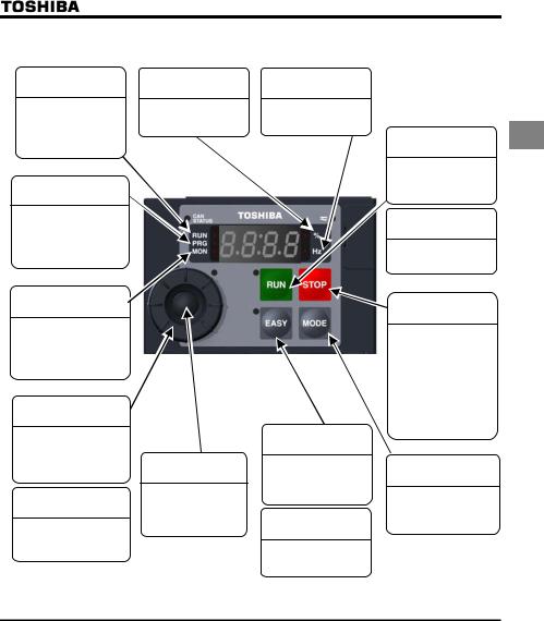
[Operation panel]
RUN lamp |
lamp |
Hz lamp |
Lit when a frequency is not output with the ON run command. This lamp blinks when operation starts.
PRG lamp
When lit, the inverter is in parameter setting mode. When blinking, the inverter is in auh.
Displayed numbers are |
Displayed numbers are |
||
in %. |
in Hertz. |
||
|
|
|
|
|
|
|
|
MON lamp
While this is lit, the inverter is in monitor mode.
While blinking, the inverter is in "Past Trip History Details Monitor Display".
Setting dial
Turning the dial left and right changes the operation frequency, parameters and etc.
Setting dial lamp
Setting the operation frequency while this lamp is lit.
Center of the
setting dial
Pressing the center of the setting dial is used for determining values.
EASY key
Switches between easy and standard setting modes.
EASY key lamp
Lights when the EASY key is enabled.
RUN key |
1 |
Pressing this key while the RUN key lamp is on starts operation.
RUN key lamp
Lights when the RUN key is enabled.
STOP key
While the RUN lamp is blinking, pressing this key once to slow down and stop the inverter.
During the terminal block operation, pressing this key twice for emergency stop. During trip, pressing this key twice for reset.
MODE key
Switches between run, settings, and status monitor modes.
A-5

E6581611
1.3.2 Opening terminal cover and terminal block
 Warning
Never touch the internal connector while the upper cover of control panel is opened. There is a risk of electrical shock because it carries a high voltage.
1 Prohibited
 Caution
Mandatory
action
When removing and mounting the terminal cover or the terminal block with a screwdriver, be sure not to scratch your hand as these results in injury.
Pressing too hard on the screwdriver can scratch the inverter.
Always turn the power off when removing the wiring cover.
After wiring is complete, be sure to replace the terminal cover.
Use the following procedure to open the terminal cover and pull the power terminal block.
Inverter type |
Procedure |
Reference |
|
|
|
number |
|
VFS15-2004PM-W to 2007PM-W |
In the beginning, remove the outside terminal |
(1) |
|
block cover. |
|||
VFS15S-2002PL-W to 2007PL-W |
|
||
Next, remove the inside terminal block cover. |
(2) |
||
|
|||
VFS15-2015PM-W to 2037PM-W |
In the beginning, remove the outside terminal |
(3) |
|
VFS15S-2015PL-W, 2022PL-W |
block cover. |
||
|
|||
VFS15-4004PL-W to 4015PL-W |
Next, remove the inside terminal block cover. |
(4) |
|
|
In the beginning, remove the outside terminal |
(3) |
|
VFS15-4022PL-W, 4037PL-W |
block cover. |
||
|
|||
|
Next, remove the inside terminal block cover. |
(5) |
|
VFS15-2055PM-W to 2150PM-W |
Follow a procedure and remove the power |
(6) |
|
VFS15-4055PL-W to 4150PL-W |
terminal cover. |
||
|
A-6
E6581611
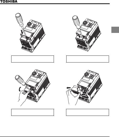
(1) Removing the outside terminal block cover (VFS15-2004PM-W to 2007PM-W, VFS15S-2002PL-W to 2007PL-W)
1) |
2) |
1
Insert a screwdriver or other thin object into the hole indicated with the 
 mark.
mark.
Press in on the screwdriver.
3) |
4) |
While pressing on the screwdriver, rotate the terminal cover downward to remove it.
Pull the terminal cover up at an angle.
●After wiring is complete, be sure to restore the terminal cover to its original position.
A-7
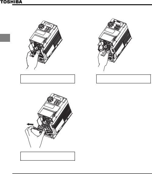
E6581611
(2) Removing the inside terminal block cover (VFS15-2004PM-W to 2007PM-W, VFS15S-2002PL-W to 2007PL-W)
1) |
2) |
1
The finger is put on to the tab part of the terminal block cover.
While pressing on the screwdriver, rotate the terminal cover downward to remove it.
3)
Pull the terminal cover up at an angle.
●After wiring is complete, be sure to restore the terminal cover to its original position.
A-8
E6581611
(3) Removing the outside terminal block cover (VFS15-2015PM-W to 2037PM-W, VFS15S-2015PL-W, 2022PL-W, VFS15-4004PL-W to 4037PL-W)
1) |
2) |
1
Insert a screwdriver or other thin object into the hole indicated with the 
 mark.
mark.
Press in on the screwdriver.
3)
While pressing on the screwdriver, sidles the terminal cover downward to remove it.
●After wiring is complete, be sure to restore the terminal cover to its original position.
A-9
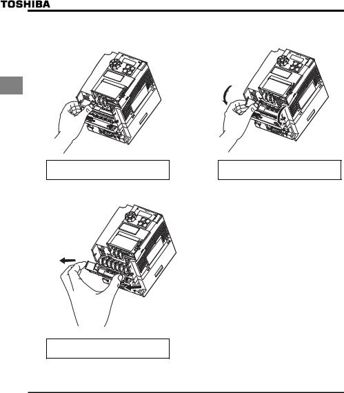
E6581611
(4) Removing the inside terminal block cover (VFS15-2015PM-W to 2037PM-W, VFS15S-2015PL-W, 2022PL-W, VFS15-4004PL-W to 4015PL-W)
1) |
2) |
|
% |
|
Hz |
|
RUN |
|
STOP |
|
EASY |
|
MODE |
1 |
|
|
R/L1 |
|
S/L2 |
|
T/L3 |
%
Hz
RUN
STOP
EASY
MODE

 R/L1
R/L1
S/L2
T/L3
The finger is put on to the tab part of the terminal block cover.
While pressing on the screwdriver, rotate the terminal cover downward to remove it.
3)
%
Hz
RUN
STOP
EASY
MODE

 R/L1
R/L1
S/L2
T/L3
Pull the terminal cover up at an angle.
●After wiring is complete, be sure to restore the terminal cover to its original position.
A-10
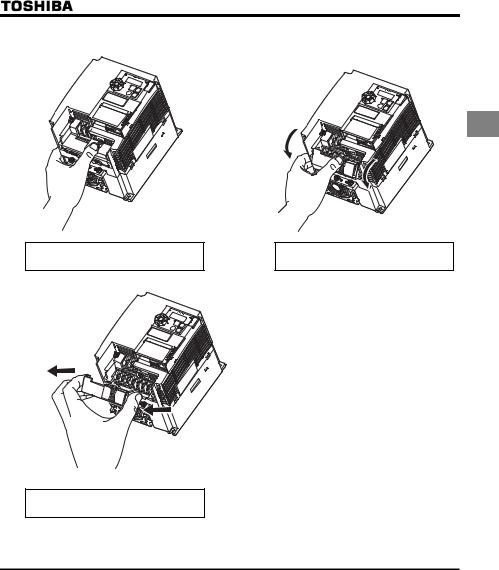
(5) Removing the inside terminal block cover (VFS15-4022PL-W, 4037PL-W)
1) |
2) |
PB
PO
PA/+
PC/-
U/-T1
 STOP
STOP
RUN
EASY
MODE
 STOP
STOP
RUN
EASY
MODE
V/-T2 |
W/-T3 |
|
PB |
PO |
|
|
|
PA/+ |
|
|
|
|
PC/- |
E6581611
1
The finger is put on to the tab part of the terminal block cover.
3)
 STOP
STOP
RUN
EASY
MODE
PB |
PO |
|
|
|
PA/+ |
|
|
|
|
PC/- |
While pressing on the screwdriver, rotate the terminal cover downward to remove it.
Pull the terminal cover up at an angle.
●After wiring is complete, be sure to restore the terminal cover to its original position.
A-11
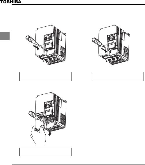
1
E6581611
(6) Removing the power terminal cover (VFS15-2055PM-W to 2150PM-W, VFS15-4055PL-W to 4150PL-W)
1) |
2) |
RUN |
STOP |
RUN |
STOP |
EASY |
MODE |
EASY |
MODE |
Insert a screwdriver or other thin object into the hole indicated with the 
 mark.
mark.
3)
RUN |
STOP |
EASY |
MODE |
Press in on the screwdriver.
While pressing on the screwdriver, slide the terminal cover downward to remove it.
●After wiring is complete, be sure to restore the terminal cover to its original position.
A-12
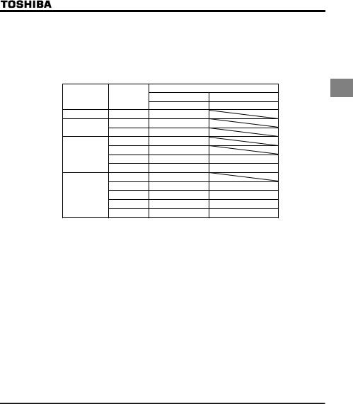
E6581611
1.3.3 Power circuit and control circuit terminal blocks
1) Power circuit terminal
In case of the lug connector, cover the lug connector with insulated tube, or use the insulated lug connector.
(Recommended Lug connectors and Insulated Tubes) |
|
1 |
|||
|
Wire Size |
Manufacturer and Type-Form |
|||
Screw Size |
Lug connector |
Insulated Tube |
|||
(mm2) |
|
||||
|
|
JST |
SHINAGAWA SHOKO |
|
|
M3.5 screw |
1.5-2.5 |
V2-M3 |
|
|
|
M4 screw |
1.5-2.5 |
V2-4 |
|
|
|
3.5-5.5 |
V5.5-4 |
|
|
||
|
|
|
|||
|
1.5-2.5 |
V2-5 |
|
|
|
M5 screw |
3.5-6.0 |
V5.5-5 |
|
|
|
8.0-10 |
R8-5 |
TCM-81 |
|
||
|
|
||||
|
14-16 |
R14-5 |
TCM-141 |
|
|
|
1.5-2.5 |
V2-6 |
|
|
|
|
3.5-6.0 |
R5.5-6 |
TCM-53 |
|
|
M6 screw |
8.0-10 |
R8-6 |
TCM-81 |
|
|
|
14-16 |
R14-6 |
TCM-141 |
|
|
|
22-25 |
R22-6 |
TCM-221 |
|
|
Use a plus or minus screwdriver to loose or tighten screws.
Screw size |
Tightening torque |
|
M3.5 screw |
1.0 Nm |
8.9 lbin |
M4 screw |
1.4 Nm |
12.4 lbin |
M5 screw |
2.4 Nm |
20.8 lbin |
M6 screw |
4.5 Nm |
40.0 lbin |
M4 screw (grounding terminal) |
1.4 Nm |
12.4 lbin |
M5 screw (grounding terminal) |
2.8 Nm |
24.8 lbin |
Refer to section 2.3.1 for details about terminal functions.
A-13
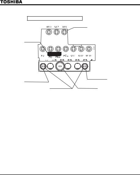
E6581611
VFS15-2004PM-W to 2007PM-W
M3.5 screw
|
|
|
|
|
|
|
|
|
|
|
|
|
|
|
|
|
|
|
|
|
|
|
|
|
|
|
|
|
|
|
|
|
|
|
|
|
|
|
|
|
|
|
|
|
|
|
|
|
|
|
|
|
|
|
|
|
|
|
|
|
|
|
|
|
|
|
|
|
|
|
|
|
|
|
|
|
|
|
|
|
|
|
|
|
|
|
|
|
|
|
|
|
|
|
|
|
|
|
|
|
|
|
|
|
|
|
|
|
|
|
|
|
|
|
|
|
|
|
|
|
|
|
|
|
|
|
|
|
|
|
|
|
|
|
|
|
|
|
|
|
|
|
|
1 |
Shorting-bar |
|
|
|
|
|
|
|
|
|
|
|
|
|
|
|
|
|
|
|
|
|
|
|
|
|
|
|
|
|
|
|
|
|
|
|
|
|
|
|
|
|
|
||||
|
|
|
|
|
|
|
|
|
|
|
|
|
|
|
|
|
|
|
|
|
|
|
|
|
|
|
|
|
|
|
|
|
|
|
|
|
|
|
|
|
|
|
|
||||
|
|
|
|
|
|
|
|
|
|
|
|
|
|
|
|
|
|
|
|
|
|
|
|
|
|
|
|
|
|
|
|
|
|
|
|
|
|
|
|
|
|
|
|
||||
|
|
|
|
|
|
|
|
|
|
|
|
|
|
|
|
|
|
|
|
|
|
|
|
|
|
|
|
|
|
|
|
|
|
|
|
|
|
|
|
|
|
|
|
|
|
|
|
|
|
|
|
|
|
|
|
|
|
|
|
|
|
|
|
|
|
|
|
|
|
|
|
|
|
|
|
|
|
|
|
|
|
|
|
|
|
|
|
|
|
|
|
|
|
|
|
|
|
|
|
|
|
|
|
|
|
|
|
|
|
|
|
|
|
|
|
|
|
|
|
|
|
|
|
|
|
|
|
|
|
|
|
|
|
|
|
|
|
|
|
|
|
|
|
|
|
|
|
|
|
|
|
|
|
|
|
|
|
|
|
|
|
|
|
|
|
|
|
|
|
|
|
|
|
|
|
|
|
|
|
|
|
|
|
|
|
|
|
|
|
|
|
|
|
|
|
|
|
|
|
|
|
|
|
|
|
|
|
|
|
|
|
|
|
|
|
|
|
|
|
|
|
|
|
|
|
|
|
|
|
|
|
|
|
|
|
|
|
|
|
|
|
|
|
|
|
|
|
|
|
|
|
|
|
|
|
|
|
|
|
|
|
|
|
|
|
|
|
|
|
|
|
|
|
|
|
|
|
|
|
|
|
|
|
|
|
|
|
|
|
|
|
|
|
|
|
|
|
|
|
|
|
|
|
|
|
|
|
|
|
|
|
|
|
|
|
|
|
|
|
|
|
|
|
|
|
|
|
|
|
|
|
|
|
|
|
|
|
|
|
|
|
|
|
|
|
|
|
|
|
|
|
|
|
|
|
|
|
|
|
|
|
|
|
|
|
|
|
|
|
|
|
|
|
|
|
|
|
|
|
|
|
|
|
|
|
|
|
|
|
|
|
|
|
|
|
|
|
|
|
|
|
|
|
|
|
|
|
|
|
|
|
|
|
|
|
|
|
|
|
|
|
|
|
|
|
|
|
|
|
|
|
|
|
|
|
|
|
|
|
|
|
|
|
|
|
|
|
|
|
|
|
|
|
|
|
|
|
|
|
|
|
|
|
|
|
|
|
|
|
|
|
|
|
|
|
|
|
|
|
|
|
|
|
|
|
|
|
|
|
|
|
|
|
|
|
|
|
|
|
|
|
|
|
|
|
|
|
|
|
|
|
|
|
|
|
|
|
|
|
|
|
|
|
|
|
|
|
|
|
|
|
|
|
|
|
|
|
|
|
|
|
|
|
|
|
|
|
|
|
|
|
|
|
|
|
|
|
|
|
|
|
|
|
|
|
|
|
|
|
|
|
|
|
|
|
|
|
|
|
|
|
|
|
|
|
|
|
|
|
|
|
|
|
|
|
|
|
|
|
|
|
|
|
|
|
|
|
|
|
|
|
|
|
|
|
|
|
|
|
|
|
|
|
|
|
|
|
|
|
|
|
|
|
|
|
|
|
|
|
|
|
|
|
|
|
|
|
|
|
|
|
|
|
|
|
|
|
|
|
|
|
|
|
|
|
|
|
|
|
|
|
|
|
|
|
|
|
|
|
|
|
|
|
|
|
|
|
|
|
|
|
|
|
|
|
|
|
|
|
|
|
|
|
|
|
|
|
|
|
|
|
|
|
|
|
|
|
|
|
Grounding terminal |
Grounding terminal |
(M4 screw) |
|
(M4 screw) |
|
|
Grounding terminal |
For EMC plate |
(M5 screw) |
Note1) Bend the clips on the wiring port of the terminal cover to connect the PB, PO, PA/+, and PC/- terminals. Note2) Be careful to insert all wires into the cage of terminal block.
A-14
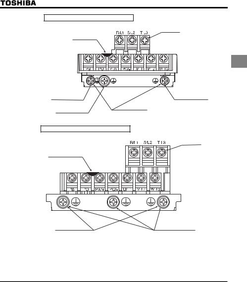
E6581611
VFS15-2015PM-W, 2022PM-W
M4 screw
Shorting-bar
1
Grounding terminal |
Grounding terminal |
|
(M4 screw) |
(M4 screw) |
|
Grounding terminal |
For EMC plate |
|
(M5 screw) |
||
|
VFS15-2037PM-W
M4 screw
Shorting-bar
|
Grounding terminal |
For EMC plate |
(M5 screw) |
Note1) Bend the clips on the wiring port of the terminal cover to connect the PB, PO, PA/+, and PC/- terminals. Note2) Be careful to insert all wires into the cage of terminal block.
A-15
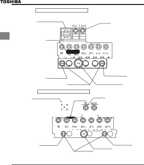
E6581611
VFS15S-2002PL-W to 2007PL-W
Grounding capacitor switch
M3.5 screw
1
Shorting-bar
|
|
|
|
|
|
|
|
|
|
|
|
|
|
|
|
|
|
|
|
|
|
|
|
|
|
|
|
|
|
|
|
|
|
|
|
|
|
|
|
|
|
|
|
|
|
|
|
|
|
|
|
|
|
|
|
|
|
|
|
|
|
|
|
|
|
|
|
|
|
|
|
|
|
|
|
|
|
|
|
|
|
|
|
|
|
|
|
|
|
|
|
|
|
|
|
|
|
|
|
|
|
|
|
|
|
|
|
|
|
|
|
|
|
|
|
|
|
|
|
|
|
|
|
|
|
|
|
|
|
|
|
|
|
|
|
|
|
|
|
|
|
|
|
|
|
|
|
|
|
|
|
|
|
|
|
|
|
|
|
|
|
|
|
|
|
|
|
|
|
|
|
|
|
|
|
|
|
|
|
|
|
|
|
|
|
|
|
|
|
|
|
|
|
|
|
|
|
|
|
|
|
|
|
|
|
|
|
|
|
|
|
|
|
|
|
|
|
|
|
|
|
|
|
|
|
|
|
|
|
|
|
|
|
|
|
|
|
|
|
|
|
|
|
|
|
|
|
|
|
|
|
|
|
|
|
|
|
|
|
|
|
|
|
|
|
|
|
|
|
|
|
|
|
|
|
|
|
|
|
|
|
|
|
|
|
|
|
|
|
|
|
|
|
|
|
|
|
|
|
|
|
|
|
|
|
|
|
|
|
|
|
|
|
|
|
|
|
|
|
|
|
|
|
|
|
|
|
|
|
|
|
|
|
|
|
|
|
|
|
|
|
|
|
|
|
|
|
|
|
|
|
|
|
|
|
|
|
|
|
|
|
|
|
|
|
|
|
|
|
|
|
|
|
|
|
|
|
|
|
|
|
|
|
|
|
|
|
|
|
|
|
|
|
|
|
|
|
|
|
|
|
|
|
|
|
|
|
|
|
|
|
|
|
|
|
|
|
|
|
|
|
|
|
|
|
|
|
|
|
|
|
|
|
|
|
|
|
|
|
|
|
|
|
|
|
|
|
|
|
|
|
|
|
|
|
|
|
|
|
|
|
|
|
|
|
|
|
|
|
|
|
|
|
|
|
|
|
|
|
|
|
|
|
|
|
|
|
|
|
|
|
|
|
|
|
|
|
|
|
|
|
|
|
|
|
|
|
|
|
|
|
|
|
|
|
|
|
|
|
|
|
|
|
|
|
|
|
|
|
|
|
|
|
|
|
|
|
|
|
|
|
|
|
|
|
|
|
|
|
|
|
|
|
|
|
|
|
|
|
|
|
Grounding terminal |
|||||||
|
|
|
|
|
|
|
|
|
|
|
|
|
|
|
|
|
|
|
|
|
|
|
|
|
|
|
|
|
|
|
|
|
|
|
|
|
|
|
|
|
|
|
|
|
|
|
|
|
||||||||
|
|
|
|
|
|
|
|
|
|
|
|
|
|
|
|
|
|
|
|
|
|
|
|
|
|
|
|
|
|
|
|
|
|
|
|
|
|
|
|
|
|
|
|
|
|
|
|
|
||||||||
|
|
|
|
|
|
|
|
|
|
|
|
|
|
|
|
|
|
|
|
|
|
|
|
|
|
|
|
|
|
|
|
|
|
|
|
|
|
|
|
|
|
|
|
|
|
|
|
|
||||||||
|
|
|
|
|
|
|
|
|
|
|
|
|
|
|
|
|
|
|
|
|
|
|
|
|
|
|
|
|
|
|
|
|
|
|
|
|
|
|
|
|
|
|
|
|
|
|
|
|
||||||||
Grounding terminal |
|
|
|
|
|
|
|
|
|
|
|
|
|
|
|
|
|
|
|
|
|
|
|
|||||||||||||||||||||||||||||||||
|
|
|
|
|
|
|
|
|
|
|
|
|
|
|
|
|
|
|
|
|
|
|
|
(M4 screw) |
||||||||||||||||||||||||||||||||
(M4 screw) |
|
|
|
|
|
|
|
|
|
|
|
|
|
|
|
|
|
|
|
|
|
|
|
|
|
|
|
|
|
|
|
|||||||||||||||||||||||||
|
|
|
|
|
|
|
|
|
|
|
|
|
|
|
|
|
|
|
|
|
|
|
|
|
|
|
|
|
|
|
|
|
|
|
|
|
|
Grounding terminal |
||||||||||||||||||
|
|
|
|
|
|
|
|
|
For EMC plate |
|
|
|
|
|
|
|
|
|
|
|
|
(M5 screw) |
||||||||||||||||||||||||||||||||||
VFS15S-2015PL-W, 2022PL-W
Grounding capacitor switch |
M4 screw |
|
Shorting-bar |
||
|
|
|
|
|
|
|
|
|
|
|
|
|
|
|
|
|
|
|
|
|
|
|
|
|
|
|
|
|
|
Grounding terminal |
|
|
|
|
|
|
|
|
|
|
|
|
|
|
|
|
|
|
|
|
|
|
|
|
|
|
|
|
|
|
|
|
|
|
|
|
|
|
|
|
|
|
|
|
|
|
|
|
|
|
|
|
|
|
|
|
|
|
|
|
|
|
|
|
|
|
|
|
|
|
|
|
|
|
|
|
|
|
|
|
|
|
|
|
|
|
|
|
|
|
|
|
|
|
|
|
|
|
|
|
|
|
|
|
|
|
|
|
|
|
|
|
|
|
|
|
|
|
|
|
|
|
|
|
|
|
|
|
|
|
|
|
|
|
|
|
|
|
|
|
|
|
|
|
|
|
|
|
|
|
|
|
|
|
|
|
|
|
|
|
|
|
|
|
|
|
|
|
|
|
|
|
|
|
|
|
|
|
|
|
|
|
|
|
|
|
|
|
|
|
|
|
|
|
|
|
|
|
|
|
|
|
|
|
|
|
|
|
|
|
|
|
|
|
|
|
|
|
|
|
|
|
|
|
|
|
|
|
|
|
|
|
|
|
|
|
|
|
|
|
|
|
|
|
|
|
|
|
|
|
|
|
|
|
|
|
|
|
|
|
|
|
|
|
|
|
|
|
|
|
|
|
|
|
|
|
|
|
|
|
|
|
|
|
|
|
|
|
|
|
|
|
|
|
|
|
|
|
|
|
Grounding terminal |
|
|
|
|
|
|
|
|
|
|
|
|
|
|
|
|
|
|
|||||||||||
(M4 screw) |
|
|
|
|
|
|
|
Grounding terminal |
|
(M4 screw) |
|||||||||||||||||||
|
|
|
|
|
|
|
|
|
|
|
|
|
|
|
|
|
|
|
|
||||||||||
|
|
|
|
|
|
|
|
|
|
|
|
|
|
|
|
|
|
(M5 screw) |
|
|
|||||||||
|
|
|
|
|
|
|
|
|
|
|
For EMC plate |
|
|
||||||||||||||||
Note1) Bend the clips on the wiring port of the terminal cover to connect the PB, PO, PA/+, and PC/- terminals. Note2) Be careful to insert all wires into the cage of terminal block.
A-16
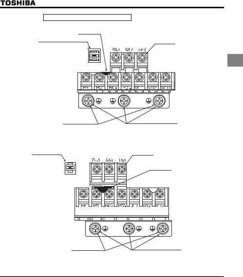
E6581611
VFS15-4004PL-W to 4015PL-W
Shorting-bar
Grounding capacitor switch
M4 screw
1
|
|
Grounding terminal |
|
For EMC plate |
(M5 screw) |
|
|
|
|
VFS15-4022PL-W, 4037PL-W |
|
Grounding capacitor |
|
|
switch |
M4 screw |
|
Shorting-bar
|
Grounding terminal |
For EMC plate |
(M5 screw) |
Note1) Bend the clips on the wiring port of the terminal cover to connect the PB, PO, PA/+, and PC/- terminals. Note2) Be careful to insert all wires into the cage of terminal block.
A-17
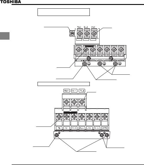
E6581611
VFS15-2055PM-W, 2075PM-W
VFS15-4055PL-W, 4075PL-W
Grounding capacitor switch
(4055PL-W, 4075PL-W only)
M5 screw
1
Shorting-bar |
|
|
Grounding terminal |
|
(M5 screw) |
Grounding terminal |
|
(M5 screw) |
For EMC plate |
|
VFS15-2110PM-W, 2150PM-W
M6 screw
Shorting-bar
Grounding terminal |
Grounding terminal |
|
(M5 screw) |
||
(M5 screw) |
||
|
||
|
For EMC plate |
Note1) Bend the clips on the wiring port of the terminal cover to connect the PB, PO, PA/+, and PC/- terminals. Note2) Be careful to insert all wires into the cage of terminal block.
A-18
 Loading...